EP2617127B2 - Method and system for providing hearing assistance to a user - Google Patents
Method and system for providing hearing assistance to a user Download PDFInfo
- Publication number
- EP2617127B2 EP2617127B2 EP10752598.2A EP10752598A EP2617127B2 EP 2617127 B2 EP2617127 B2 EP 2617127B2 EP 10752598 A EP10752598 A EP 10752598A EP 2617127 B2 EP2617127 B2 EP 2617127B2
- Authority
- EP
- European Patent Office
- Prior art keywords
- audio signals
- gain
- ambient noise
- level
- speech
- Prior art date
- Legal status (The legal status is an assumption and is not a legal conclusion. Google has not performed a legal analysis and makes no representation as to the accuracy of the status listed.)
- Active
Links
- 238000000034 method Methods 0.000 title claims description 14
- 230000005236 sound signal Effects 0.000 claims description 74
- 230000005540 biological transmission Effects 0.000 claims description 31
- 230000006870 function Effects 0.000 claims description 19
- 230000004936 stimulating effect Effects 0.000 claims description 11
- 230000007423 decrease Effects 0.000 claims description 8
- 230000003247 decreasing effect Effects 0.000 claims description 6
- 230000000694 effects Effects 0.000 claims description 3
- 230000000638 stimulation Effects 0.000 claims 2
- 230000008901 benefit Effects 0.000 description 10
- 238000010586 diagram Methods 0.000 description 7
- 230000003321 amplification Effects 0.000 description 3
- 230000001419 dependent effect Effects 0.000 description 3
- 210000000613 ear canal Anatomy 0.000 description 3
- 210000005069 ears Anatomy 0.000 description 3
- 238000003199 nucleic acid amplification method Methods 0.000 description 3
- 230000007704 transition Effects 0.000 description 3
- 208000032041 Hearing impaired Diseases 0.000 description 2
- 238000004458 analytical method Methods 0.000 description 2
- 208000021900 auditory perceptual disease Diseases 0.000 description 2
- 230000007613 environmental effect Effects 0.000 description 2
- 206010011878 Deafness Diseases 0.000 description 1
- 230000009286 beneficial effect Effects 0.000 description 1
- 230000006835 compression Effects 0.000 description 1
- 238000007906 compression Methods 0.000 description 1
- 230000010370 hearing loss Effects 0.000 description 1
- 231100000888 hearing loss Toxicity 0.000 description 1
- 208000016354 hearing loss disease Diseases 0.000 description 1
- 238000001228 spectrum Methods 0.000 description 1
Images


Classifications
-
- H—ELECTRICITY
- H04—ELECTRIC COMMUNICATION TECHNIQUE
- H04R—LOUDSPEAKERS, MICROPHONES, GRAMOPHONE PICK-UPS OR LIKE ACOUSTIC ELECTROMECHANICAL TRANSDUCERS; DEAF-AID SETS; PUBLIC ADDRESS SYSTEMS
- H04R25/00—Deaf-aid sets, i.e. electro-acoustic or electro-mechanical hearing aids; Electric tinnitus maskers providing an auditory perception
-
- H—ELECTRICITY
- H03—ELECTRONIC CIRCUITRY
- H03G—CONTROL OF AMPLIFICATION
- H03G3/00—Gain control in amplifiers or frequency changers without distortion of the input signal
- H03G3/20—Automatic control
- H03G3/30—Automatic control in amplifiers having semiconductor devices
- H03G3/32—Automatic control in amplifiers having semiconductor devices the control being dependent upon ambient noise level or sound level
-
- H—ELECTRICITY
- H04—ELECTRIC COMMUNICATION TECHNIQUE
- H04R—LOUDSPEAKERS, MICROPHONES, GRAMOPHONE PICK-UPS OR LIKE ACOUSTIC ELECTROMECHANICAL TRANSDUCERS; DEAF-AID SETS; PUBLIC ADDRESS SYSTEMS
- H04R25/00—Deaf-aid sets, i.e. electro-acoustic or electro-mechanical hearing aids; Electric tinnitus maskers providing an auditory perception
- H04R25/35—Deaf-aid sets, i.e. electro-acoustic or electro-mechanical hearing aids; Electric tinnitus maskers providing an auditory perception using translation techniques
- H04R25/356—Amplitude, e.g. amplitude shift or compression
-
- H—ELECTRICITY
- H04—ELECTRIC COMMUNICATION TECHNIQUE
- H04R—LOUDSPEAKERS, MICROPHONES, GRAMOPHONE PICK-UPS OR LIKE ACOUSTIC ELECTROMECHANICAL TRANSDUCERS; DEAF-AID SETS; PUBLIC ADDRESS SYSTEMS
- H04R25/00—Deaf-aid sets, i.e. electro-acoustic or electro-mechanical hearing aids; Electric tinnitus maskers providing an auditory perception
- H04R25/55—Deaf-aid sets, i.e. electro-acoustic or electro-mechanical hearing aids; Electric tinnitus maskers providing an auditory perception using an external connection, either wireless or wired
- H04R25/554—Deaf-aid sets, i.e. electro-acoustic or electro-mechanical hearing aids; Electric tinnitus maskers providing an auditory perception using an external connection, either wireless or wired using a wireless connection, e.g. between microphone and amplifier or using Tcoils
-
- H—ELECTRICITY
- H04—ELECTRIC COMMUNICATION TECHNIQUE
- H04R—LOUDSPEAKERS, MICROPHONES, GRAMOPHONE PICK-UPS OR LIKE ACOUSTIC ELECTROMECHANICAL TRANSDUCERS; DEAF-AID SETS; PUBLIC ADDRESS SYSTEMS
- H04R2225/00—Details of deaf aids covered by H04R25/00, not provided for in any of its subgroups
- H04R2225/41—Detection or adaptation of hearing aid parameters or programs to listening situation, e.g. pub, forest
-
- H—ELECTRICITY
- H04—ELECTRIC COMMUNICATION TECHNIQUE
- H04R—LOUDSPEAKERS, MICROPHONES, GRAMOPHONE PICK-UPS OR LIKE ACOUSTIC ELECTROMECHANICAL TRANSDUCERS; DEAF-AID SETS; PUBLIC ADDRESS SYSTEMS
- H04R2225/00—Details of deaf aids covered by H04R25/00, not provided for in any of its subgroups
- H04R2225/43—Signal processing in hearing aids to enhance the speech intelligibility
-
- H—ELECTRICITY
- H04—ELECTRIC COMMUNICATION TECHNIQUE
- H04R—LOUDSPEAKERS, MICROPHONES, GRAMOPHONE PICK-UPS OR LIKE ACOUSTIC ELECTROMECHANICAL TRANSDUCERS; DEAF-AID SETS; PUBLIC ADDRESS SYSTEMS
- H04R2460/00—Details of hearing devices, i.e. of ear- or headphones covered by H04R1/10 or H04R5/033 but not provided for in any of their subgroups, or of hearing aids covered by H04R25/00 but not provided for in any of its subgroups
- H04R2460/01—Hearing devices using active noise cancellation
-
- H—ELECTRICITY
- H04—ELECTRIC COMMUNICATION TECHNIQUE
- H04R—LOUDSPEAKERS, MICROPHONES, GRAMOPHONE PICK-UPS OR LIKE ACOUSTIC ELECTROMECHANICAL TRANSDUCERS; DEAF-AID SETS; PUBLIC ADDRESS SYSTEMS
- H04R25/00—Deaf-aid sets, i.e. electro-acoustic or electro-mechanical hearing aids; Electric tinnitus maskers providing an auditory perception
- H04R25/40—Arrangements for obtaining a desired directivity characteristic
- H04R25/407—Circuits for combining signals of a plurality of transducers
-
- H—ELECTRICITY
- H04—ELECTRIC COMMUNICATION TECHNIQUE
- H04R—LOUDSPEAKERS, MICROPHONES, GRAMOPHONE PICK-UPS OR LIKE ACOUSTIC ELECTROMECHANICAL TRANSDUCERS; DEAF-AID SETS; PUBLIC ADDRESS SYSTEMS
- H04R25/00—Deaf-aid sets, i.e. electro-acoustic or electro-mechanical hearing aids; Electric tinnitus maskers providing an auditory perception
- H04R25/43—Electronic input selection or mixing based on input signal analysis, e.g. mixing or selection between microphone and telecoil or between microphones with different directivity characteristics
-
- H—ELECTRICITY
- H04—ELECTRIC COMMUNICATION TECHNIQUE
- H04R—LOUDSPEAKERS, MICROPHONES, GRAMOPHONE PICK-UPS OR LIKE ACOUSTIC ELECTROMECHANICAL TRANSDUCERS; DEAF-AID SETS; PUBLIC ADDRESS SYSTEMS
- H04R25/00—Deaf-aid sets, i.e. electro-acoustic or electro-mechanical hearing aids; Electric tinnitus maskers providing an auditory perception
- H04R25/50—Customised settings for obtaining desired overall acoustical characteristics
- H04R25/505—Customised settings for obtaining desired overall acoustical characteristics using digital signal processing
Definitions
- the present invention relates to a method for providing hearing assistance to a user; it also relates to a corresponding system comprising a microphone arrangement for capturing audio signals, audio signal processing means and means for stimulating the hearing of the user according to the processed audio signals.
- One type of hearing assistance systems is represented by wireless systems, wherein the microphone arrangement is part of a transmission unit for transmitting the audio signals via a wireless audio link to a receiver unit comprising or being connected to the stimulating means.
- the wireless audio link is an narrow band FM radio link.
- the benefit of such systems is that sound captured by a remote microphone at the transmission unit can be presented at a much better SNR to the user wearing the receiver unit at his ear(s).
- the stimulating means is loudspeaker which is part of the receiver unit or is connected thereto.
- Such systems are particularly helpful in teaching environments for normal-hearing children suffering from auditory processing disorders (APD), wherein the teacher's voice is captured by the microphone of the transmission unit, and the corresponding audio signals are transmitted to and are reproduced by the receiver unit worn by the child, so that the teacher's voice can be heard by the child at an enhanced level, in particular with respect to the background noise level prevailing in the classroom. It is well known that presentation of the teacher's voice at such enhanced level supports the child in listening to the teacher.
- APD auditory processing disorders
- the receiver unit is connected to or integrated into a hearing instrument, such as a hearing aid.
- a hearing instrument such as a hearing aid.
- the benefit of such systems is that the microphone of the hearing instrument can be supplemented or replaced by the remote microphone which produces audio signals which are transmitted wirelessly to the FM receiver and thus to the hearing instrument.
- FM systems have been standard equipment for children with hearing loss in educational settings for many years. Their merit lies in the fact that a microphone placed a few inches from the mouth of a person speaking receives speech at a much higher level than one placed several feet away. This increase in speech level corresponds to an increase in signal-to-noise ratio (SNR) due to the direct wireless connection to the listener's amplification system.
- SNR signal-to-noise ratio
- the resulting improvements of signal level and SNR in the listener's ear are recognized as the primary benefits of FM radio systems, as hearing-impaired individuals are at a significant disadvantage when processing signals with a poor acoustical SNR.
- FM+M the FM plus hearing instrument combination
- FM+ENV the FM plus hearing instrument combination
- This operating mode allows the listener to perceive the speaker's voice from the remote microphone with a good SNR while the integrated hearing instrument microphone allows the listener to also hear environmental sounds. This allows the user/listener to hear and monitor his own voice, as well as voices of other people or environmental noise, as long as the loudness balance between the FM signal and the signal coming from the hearing instrument microphone is properly adjusted.
- FM advantage measures the relative loudness of signals when both the FM signal and the hearing instrument microphone are active at the same time.
- FM advantage compares the levels of the FM signal and the local microphone signal when the speaker and the user of an FM system are spaced by a distance of two meters.
- the voice of the speaker will travel approximately 30 cm to the input of the FM microphone at a level of approximately 80 dB-SPL, whereas only about 65 dB-SPL will remain of this original signal after traveling the 2 m distance to the microphone in the hearing instrument.
- the ASHA guidelines recommend that the FM signal should have a level 10 dB higher than the level of the hearing instrument's microphone signal at the output of the user's hearing instrument in this particular configuration of talker and listener.
- the relative gain i.e. the ratio of the gain applied to the audio signals produced by the FM microphone and the gain applied to the audio signals produced by the hearing instrument microphone
- the relative gain has to be set to a fixed value in order to achieve e.g. the recommended FM advantage of 10 dB under the above-mentioned specific conditions.
- the audio output of the FM receiver usually has been adjusted in such a way that the desired FM advantage is either fixed or programmable by a professional, so that during use of the system the FM advantage - and hence the gain ratio - is constant in the FM+M mode of the FM receiver.
- Contemporary digital hearing aids are capable of permanently performing a classification of the present auditory scene captured by the hearing aid microphones in order to select that hearing aid operation mode which is most appropriate for the determined present auditory scene.
- Examples of such hearing aids including auditory scene analysis can be found in US 2002/0037087 , US 2002/0090098 , WO 02/032208 and US 2002/0150264 .
- EP 1 729 410 A1 relates to a mobile phone system wherein a gain model is applied to the audio signals received by a mobile phone from the base station and to the audio signals captured by the microphone of a mobile phone.
- the signal is analyzed in order to determine whether audio data, such as speech, is present in the signal or whether there is only noise in the signal.
- the gain is set to a low first level; in case that audio data as found in the signal, the gain is set to a second level which is higher than the first level. For high signal levels there is no such signal analysis and the gain is set in a manner to be dependent on the determined signal level.
- EP 1 691 574 A2 relates to a wireless system, wherein the transmission unit comprises two spaced-apart microphones, a beam former and a classification unit for controlling the gain applied in the receiver unit to the transmitted audio signals according to the presently prevailing auditory scene.
- the classification unit generates control commands which are transmitted to the receiver unit via a common link together with the audio signals.
- the receiver unit may be part of or connected to a hearing instrument.
- the classification unit comprises a voice energy estimator and a surrounding noise level estimator in order to decide whether there is a voice close to the microphones or not, with the gain to be applied in the receiver unit being set accordingly.
- the voice energy estimator uses the output signal of the beam former for determining the total energy contained in the voice spectrum.
- a similar system is known from EP 1 819 195 A2 , wherein the receiver unit comprises a loudspeaker rather than being part of or connected to a hearing instrument.
- the gain applied in the receiver unit is set according to the present auditory scene as detected by a classification unit located in the transmission unit.
- the transmission unit includes a gain model according to which the gain applied to the audio signals supplied by the microphones of the transmission unit prior to being transmitted to the receiver unit is controlled in a manner such as to avoid too high sound levels at the loudspeaker, i.e. the gain is reduced at high sound input levels ("compression").
- the gain model applied in the transmission unit is fixed and includes at least a linear range of the level of the input audio signals in which the gain is constant and a compressive range of the level of the input audio signals in which the gain decreases from the constant gain value of the linear range with increasing level of the input audio signals, wherein the boundary between the linear range and the compressive range is formed by a so-called kneepoint; in other words, the gain is constant at low input levels and it is decreasing with a certain slope at higher input levels.
- a typical value of the kneepoint is about 73 dB SPL (Sound Pressure Level) of the input signal.
- wireless microphones may have variable distances to the mouth of the speaker (unless the microphone is a boom microphone). At large distances and/or in case of soft voices the speech level may be below the kneepoint level of the gain model of the transmission unit. In this case, amplification of these signals would not be as high as desirable (since the position of the slope of the compressive range is always the same, a relatively too high kneepoint corresponds to a relatively too low amplification at low input levels). Hence, especially in quiet conditions, soft voices or voices at a larger distance from the microphone may become too soft, or when the distance to the mouth varies the sound level may vary accordingly, resulting in an uneven sound image.
- this object is achieved by a method as defined in claim 1 and a system as defined in claim 11 respectively.
- the invention is beneficial in that, by applying a gain model wherein, for a each ambient noise level, the gain varies as a function of the speech level and wherein the function varies according the ambient noise level in such a manner that the ratio of the gain at low spech levels and at high speech levels changes as a function of the ambient noise level, the effect of the distance of the microphone to the mouth of the speaker on the sound level in quiet conditions and at lower speech levels is reduced, whereby sound levels can be made more stable and the allowed maximal distance between the speaker and the microphone is increased.
- a gain model wherein, for a each ambient noise level, the gain varies as a function of the speech level and wherein the function varies according the ambient noise level in such a manner that the ratio of the gain at low spech levels and at high speech levels changes as a function of the ambient noise level, the effect of the distance of the microphone to the mouth of the speaker on the sound level in quiet conditions and at lower speech levels is reduced, whereby sound levels can be made more stable and the allowed maximal distance between the speaker and
- the gain model comprises a linear range in which the gain is constant irrespective of the speech level of the input audio signals and a compressive range which is adjacent to the linear range and in which compressive range the gain decreases with a given slope from the constant gain value of the linear range with increasing speech level of the input audio signals, wherein the boundary between the linear range and the compressive range is formed by a kneepoint, and wherein the position of the kneepoint is a function of the ambient noise level while the slope of the compressive range remains fixed so that the constant gain value of the linear range varies according to the position of the kneepoint.
- the kneepoint is shifted to lower speech levels of the input audio signals with decreasing ambient noise levels, wherein the kneepoint is constant above a given threshold value of the ambient noise level.
- reducing the kneepoint to lower speech input levels corresponds to increasing the gain in the system, which will not improve the SNR at the microphone position, but will result in making the speech signal less susceptive to changes in level, which may be caused by variations in the distance between the speaker's mouth and the microphone.
- the higher gain will also result in a better SNR at ear level, provided the ambient noise level is low enough.
- the gain applied in the receiver unit to the audio signals received from the transmission unit may be constant or it may be variable depending on the presently prevailing auditory scene.
- the system may comprise a classification unit located in the transmission unit for analyzing the audio signals prior to being transmitted in order to determine a present auditory scene category from a plurality of auditory scene categories; a gain control unit located in the receiver unit for setting the gain applied to the audio signals; and means for transmitting gain control commands from the transmission unit to the gain control unit in order to set, by the gain control unit, the gain applied to the audio signals according to the present auditory scene category.
- the term “kneepoint” may designate both a (very short range) of sharp transition of the gain and a (more extended) range of gradual transition of the gain, i.e. a smoother transition of the gain between the linear range and the compressive range.
- Fig. 1 shows a block diagram of an example of a wireless hearing assistance system comprising a transmission unit 10 and at least one ear unit 12 which is to be worn at or in one of the user's ears (an ear unit 12 may be provided only for one of the two ears of the user, or an ear unit 12 may be provided for each of the ears).
- a transmission unit 10 and at least one ear unit 12 which is to be worn at or in one of the user's ears
- an ear unit 12 may be provided only for one of the two ears of the user, or an ear unit 12 may be provided for each of the ears.
- the ear unit 12 comprises a receiver unit 14, which may supply its output signal to a hearing instrument 16 which is mechanically and electrically connected to the receiver unit 14, for example, via a standardized interface 17 (such as a so-called "audio shoe"), or, according to a variant, to a loudspeaker 18, which is worn at least in part in the user's ear canal (for example, the loudspeaker itself may be located in the ear canal or a sound tube may extend from the loudspeaker located at the ear into the ear canal).
- a standardized interface 17 such as a so-called "audio shoe”
- a loudspeaker 18 which is worn at least in part in the user's ear canal
- the loudspeaker itself may be located in the ear canal or a sound tube may extend from the loudspeaker located at the ear into the ear canal.
- the hearing instrument 16 usually will be a hearing aid, such as of the BTE (Behind The Ear)-type, the ITE (In The Ear)-type or the CIC (Completely In the Canal)-type.
- the hearing instrument 16 comprises one or more microphones 20, a central unit 22 for performing audio signal processing and for controlling the hearing instrument 16, a power amplifier 24 and a loudspeaker 26.
- the transmission unit 10 comprises a transmitter 30 and an antenna 32 for transmitting audio signals processed in a central signal processing unit 46 via a wireless link 34 to the receiver unit 14, which comprises an antenna 36, a receiver 38 and a signal processing unit 40 for receiving the audio signals transmitted via the link 34 in order to supply them to the hearing instrument 16 or the speaker 18.
- the wireless audio link 34 preferably is an FM (frequency modulation) link, but it could also be a different wireless link, like a digital radio link.
- the ear unit 12 may consist of a hearing instrument 16' into which the functionality of the receiver unit 14, i.e. the antenna 36 and the receiver 38, is integrated. Such an alternative is also schematically shown in Fig. 1 .
- the transmission unit 10 comprises a microphone arrangement 42, which usually comprises at least two spaced-apart microphones M1 and M2, a beam-former 44, an audio signal processing unit 46, an ambient noise estimation unit 48 and an input speech level estimation unit 52.
- a microphone arrangement 42 which usually comprises at least two spaced-apart microphones M1 and M2, a beam-former 44, an audio signal processing unit 46, an ambient noise estimation unit 48 and an input speech level estimation unit 52.
- the microphone arrangement 42 is provided for capturing audio signals from ambient sound, usually the voice of a person, such as a teacher, using the transmission unit 10, which audio signals are supplied to the beam former 44, wherein an acoustic beam forming algorithm is applied to the input audio signals.
- the output signal of the beam-former 44 is supplied to the audio signal processing unit 46.
- the input audio signals of at least one of the microphones M1, M2 of the microphone arrangement 42 are also supplied to the ambient noise estimation unit 48, which supplies a corresponding output signal to the audio signal processing unit 46 in order to control the audio signal processing according to the ambient noise level, and to the input speech level estimation unit 52, which estimates the input speech level of the audio signals captured by the microphone arrangement 42 in order to supply this parameter to the gain model implemented in the audio signal processing unit 46.
- the ambient noise level is averaged over 5 to 15 seconds.
- the transmission unit 10 is designed as a portable unit which may serve several purposes: it may be worn around a person's neck, usually a person speaking to the user of the ear unit 10, such as the teacher in a classroom teaching hearing-impaired persons, or a guide in a museum, etc.; it may be placed stationary on a table, for example, during a conference meeting; it may be held in the hand of the user of the ear unit 12; or it may be worn at the body of the user of the ear unit 12.
- the audio signal processing unit 46 includes a gain model, and usually other elements, such as noise cancelling algorithms and/or an equalizer, i.e. a frequency-dependent gain control.
- Fig. 3 An example of the gain model implemented in the audio signal processing unit 46 is shown in Fig. 3 , according to which the gain model comprises a linear range at levels of the input speech signal which are below a kneepoint level K n , which depends on the presently estimated ambient noise level, for example, in the manner shown in Fig. 2 , and a compressive range at levels of the input speech signal above the kneepoint.
- the gain is constant, i.e. it does not depend on the input speech level
- the compressive range the gain decreases from the constant gain value of the linear range with a fixed slope with increasing input speech levels (in the double-logarithmic representation of Fig. 3 the decrease in the compressive range is linear).
- the gain model comprises a linear range at levels of the input speech signal which are below a kneepoint level K n , which depends on the presently estimated ambient noise level, for example, in the manner shown in Fig. 2 , and a compressive range at levels of the input speech signal above the kneepoint.
- the gain is
- the gain curve is shown for three different values (levels) of the kneepoint, namely at 63, 68 and 73 dB, respectively. Due to the fixed slope of the compressive range, the constant gain value of the linear range increases when the level of the kneepoint decreases.
- the gain may be progressively reduced from the constant value of the linear range with decreasing input speech levels ("soft squelch” or “expansion”) in order to avoid transmission of noise signals at very low speech levels (this optional feature is not shown in Figs. 2 to 6 ).
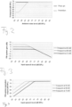
- Fig. 2 shows an example of how the kneepoint level may vary as a function of the ambient noise level, wherein the kneepoint level is constant, for example, at 73 dB SPL, for ambient noise levels above 65 dB SPL, while it decreases with decreasing ambient noise level to 63 dB at ambient noise levels below 53 dB.
- Fig. 2 also shows the constant, i.e. ambient noise level independent, kneepoint level of devices of the prior art, wherein in the example the kneepoint level is constant at 73 dB.
- Fig. 4 shows the corresponding FM system equivalent output as a function of the input speech level for the three different kneepoint levels of Fig. 3 , where it can be seen that shifting the kneepoint to lower input speech levels causes the lower input speech levels to be mapped at higher output levels.
- the SNR at ear level is determined by the noise and speech levels at the microphone arrangement 42 and at the hearing instrument microphone 20, by the gain applied by the FM system and by the distance between the speaking person and the listening person. At least for relatively low sound levels of the speech at the microphone arrangement 42 of the transmission unit 10 it can be assumed that the speech level directly arriving at the hearing aid microphone 20 has no influence on the experienced SNR, the more as the distance between the speaking person and the hearing aid microphone 20 usually will be relatively large.
- the SNR at ear level is shown in Fig. 5 , where K stands for the kneepoint level and N stands for the ambient noise level. It can be seen in Fig. 5 that lowering the kneepoint level results in an improved SNR at low input speech levels for the same ambient noise level. It is important that lower kneepoint levels occur only when the ambient noise level is sufficiently low.
- Fig. 6 the SNR improvement by a kneepoint level of 73 dB versus a kneepoint level of 68 dB is compared to the improvement by a kneepoint level of 73 dB versus a kneepoint level of 63 dB. It can be seen from Fig. 6 that in the latter case the SNR improvement is more pronounced at low input speech levels.
- the transmission unit 10 may include a voice activity detector 50 for estimating the presence of speech close to the microphone arrangement 42, in order to adapt the audio signal processing scheme in the audio signal processing unit 46 accordingly.
- a voice activity detector 50 for estimating the presence of speech close to the microphone arrangement 42, in order to adapt the audio signal processing scheme in the audio signal processing unit 46 accordingly.
- the gain applied to the audio signals received in the receiver unit 14 is constant, i.e. it does not depend on the present auditory scene.
- the system may be modified in such a manner that the gain applied to the received audio signals in the receiver unit 14 is variable depending on the present auditory scene as classified by a classifier implemented in the transmission unit 10.
- the transmission unit 10 not only transmits the audio signals to the receiver unit, but in addition it also transmits control commands for setting the gain in the receiver unit 14 according to the auditory scene as detected by the classifier in the transmission unit 10. Examples of such variable gain devices are described in WO 2008/138365 , EP 1 691 574 A2 , EP 1 819 195 A2 and EP 1 863 320 A1 .
- the gain may be progressively reduced from the constant value of the linear range with decreasing input speech levels ("soft squelch” or “expansion”) in order to avoid transmission of noise signals at very low speech levels (this optional feature is not shown in Figs. 2 to 6 ).
Description
- The present invention relates to a method for providing hearing assistance to a user; it also relates to a corresponding system comprising a microphone arrangement for capturing audio signals, audio signal processing means and means for stimulating the hearing of the user according to the processed audio signals.
- One type of hearing assistance systems is represented by wireless systems, wherein the microphone arrangement is part of a transmission unit for transmitting the audio signals via a wireless audio link to a receiver unit comprising or being connected to the stimulating means. Usually in such systems the wireless audio link is an narrow band FM radio link. The benefit of such systems is that sound captured by a remote microphone at the transmission unit can be presented at a much better SNR to the user wearing the receiver unit at his ear(s).
- According to one typical application of such wireless audio systems, the stimulating means is loudspeaker which is part of the receiver unit or is connected thereto. Such systems are particularly helpful in teaching environments for normal-hearing children suffering from auditory processing disorders (APD), wherein the teacher's voice is captured by the microphone of the transmission unit, and the corresponding audio signals are transmitted to and are reproduced by the receiver unit worn by the child, so that the teacher's voice can be heard by the child at an enhanced level, in particular with respect to the background noise level prevailing in the classroom. It is well known that presentation of the teacher's voice at such enhanced level supports the child in listening to the teacher.
- According to another typical application of wireless audio systems the receiver unit is connected to or integrated into a hearing instrument, such as a hearing aid. The benefit of such systems is that the microphone of the hearing instrument can be supplemented or replaced by the remote microphone which produces audio signals which are transmitted wirelessly to the FM receiver and thus to the hearing instrument. In particular, FM systems have been standard equipment for children with hearing loss in educational settings for many years. Their merit lies in the fact that a microphone placed a few inches from the mouth of a person speaking receives speech at a much higher level than one placed several feet away. This increase in speech level corresponds to an increase in signal-to-noise ratio (SNR) due to the direct wireless connection to the listener's amplification system. The resulting improvements of signal level and SNR in the listener's ear are recognized as the primary benefits of FM radio systems, as hearing-impaired individuals are at a significant disadvantage when processing signals with a poor acoustical SNR.
- Most FM systems in use today provide two or three different operating modes. The choices are to get the sound from: (1) the hearing instrument microphone alone, (2) the FM microphone alone, or (3) a combination of FM and hearing instrument microphones together.
- Usually, most of the time the FM system is used in mode (3), i.e. the FM plus hearing instrument combination (often labeled "FM+M" or "FM+ENV" mode). This operating mode allows the listener to perceive the speaker's voice from the remote microphone with a good SNR while the integrated hearing instrument microphone allows the listener to also hear environmental sounds. This allows the user/listener to hear and monitor his own voice, as well as voices of other people or environmental noise, as long as the loudness balance between the FM signal and the signal coming from the hearing instrument microphone is properly adjusted. The so-called "FM advantage" measures the relative loudness of signals when both the FM signal and the hearing instrument microphone are active at the same time. As defined by the ASHA (American Speech-Language-Hearing Association 2002), FM advantage compares the levels of the FM signal and the local microphone signal when the speaker and the user of an FM system are spaced by a distance of two meters. In this example, the voice of the speaker will travel approximately 30 cm to the input of the FM microphone at a level of approximately 80 dB-SPL, whereas only about 65 dB-SPL will remain of this original signal after traveling the 2 m distance to the microphone in the hearing instrument. The ASHA guidelines recommend that the FM signal should have a
level 10 dB higher than the level of the hearing instrument's microphone signal at the output of the user's hearing instrument in this particular configuration of talker and listener. - When following the ASHA guidelines (or any similar recommendation), the relative gain, i.e. the ratio of the gain applied to the audio signals produced by the FM microphone and the gain applied to the audio signals produced by the hearing instrument microphone, has to be set to a fixed value in order to achieve e.g. the recommended FM advantage of 10 dB under the above-mentioned specific conditions. Accordingly, - depending on the type of hearing instrument used - the audio output of the FM receiver usually has been adjusted in such a way that the desired FM advantage is either fixed or programmable by a professional, so that during use of the system the FM advantage - and hence the gain ratio - is constant in the FM+M mode of the FM receiver.
- Contemporary digital hearing aids are capable of permanently performing a classification of the present auditory scene captured by the hearing aid microphones in order to select that hearing aid operation mode which is most appropriate for the determined present auditory scene. Examples of such hearing aids including auditory scene analysis can be found in
US 2002/0037087 ,US 2002/0090098 ,WO 02/032208 US 2002/0150264 . -
EP 1 729 410 A1 -
EP 1 691 574 A2 - A similar system is known from
EP 1 819 195 A2 - In all of such wireless systems, irrespective of whether the gain applied in the receiver unit is constant or variable, the transmission unit includes a gain model according to which the gain applied to the audio signals supplied by the microphones of the transmission unit prior to being transmitted to the receiver unit is controlled in a manner such as to avoid too high sound levels at the loudspeaker, i.e. the gain is reduced at high sound input levels ("compression"). Usually the gain model applied in the transmission unit is fixed and includes at least a linear range of the level of the input audio signals in which the gain is constant and a compressive range of the level of the input audio signals in which the gain decreases from the constant gain value of the linear range with increasing level of the input audio signals, wherein the boundary between the linear range and the compressive range is formed by a so-called kneepoint; in other words, the gain is constant at low input levels and it is decreasing with a certain slope at higher input levels. A typical value of the kneepoint is about 73 dB SPL (Sound Pressure Level) of the input signal. There are also systems including a dynamic gain model rather than a fixed gain model, wherein ambient noise may cause the system to increase the overall gain, while leaving the position of the kneepoint constant, which improves the signal to noise ratio in the FM+M mode in the hearing instrument. While such a dynamic gain model improves signal to noise ratio in noisy surroundings, it does not offer a solution for soft speech input levels in fairly quiet conditions.
- In general, wireless microphones may have variable distances to the mouth of the speaker (unless the microphone is a boom microphone). At large distances and/or in case of soft voices the speech level may be below the kneepoint level of the gain model of the transmission unit. In this case, amplification of these signals would not be as high as desirable (since the position of the slope of the compressive range is always the same, a relatively too high kneepoint corresponds to a relatively too low amplification at low input levels). Hence, especially in quiet conditions, soft voices or voices at a larger distance from the microphone may become too soft, or when the distance to the mouth varies the sound level may vary accordingly, resulting in an uneven sound image.
- It is an object of the invention to provide for a method and a system for providing hearing assistance to a user by using a wireless microphone, wherein the user comfort and benefit should be enhanced.
- According to the invention, this object is achieved by a method as defined in
claim 1 and a system as defined in claim 11 respectively. - The invention is beneficial in that, by applying a gain model wherein, for a each ambient noise level, the gain varies as a function of the speech level and wherein the function varies according the ambient noise level in such a manner that the ratio of the gain at low spech levels and at high speech levels changes as a function of the ambient noise level, the effect of the distance of the microphone to the mouth of the speaker on the sound level in quiet conditions and at lower speech levels is reduced, whereby sound levels can be made more stable and the allowed maximal distance between the speaker and the microphone is increased. Thereby user comfort, user benefit and hence acceptance and usage of wireless microphones can be increased.
- The gain model comprises a linear range in which the gain is constant irrespective of the speech level of the input audio signals and a compressive range which is adjacent to the linear range and in which compressive range the gain decreases with a given slope from the constant gain value of the linear range with increasing speech level of the input audio signals, wherein the boundary between the linear range and the compressive range is formed by a kneepoint, and wherein the position of the kneepoint is a function of the ambient noise level while the slope of the compressive range remains fixed so that the constant gain value of the linear range varies according to the position of the kneepoint.
- Preferably, the kneepoint is shifted to lower speech levels of the input audio signals with decreasing ambient noise levels, wherein the kneepoint is constant above a given threshold value of the ambient noise level. At low ambient noise levels, reducing the kneepoint to lower speech input levels corresponds to increasing the gain in the system, which will not improve the SNR at the microphone position, but will result in making the speech signal less susceptive to changes in level, which may be caused by variations in the distance between the speaker's mouth and the microphone. The higher gain will also result in a better SNR at ear level, provided the ambient noise level is low enough.
- The gain applied in the receiver unit to the audio signals received from the transmission unit may be constant or it may be variable depending on the presently prevailing auditory scene. In the latter case the system may comprise a classification unit located in the transmission unit for analyzing the audio signals prior to being transmitted in order to determine a present auditory scene category from a plurality of auditory scene categories; a gain control unit located in the receiver unit for setting the gain applied to the audio signals; and means for transmitting gain control commands from the transmission unit to the gain control unit in order to set, by the gain control unit, the gain applied to the audio signals according to the present auditory scene category.
- Preferred embodiments of the invention are defined in the dependent claims.
- For the purposes of the present invention, the term "kneepoint" may designate both a (very short range) of sharp transition of the gain and a (more extended) range of gradual transition of the gain, i.e. a smoother transition of the gain between the linear range and the compressive range.
- In the following, examples of the invention will be illustrated by reference to the attached drawings, wherein:
- Fig. 1
- is a block diagram of an example of a hearing assistance system according to the invention;
- Fig. 2
- is a diagram which shows an example of the kneepoint level of the gain model used in the transmission unit of the system of
Fig. 1 as a function of the ambient noise level; - Fig. 3
- is a diagram which shows an example of the gain applied in the gain model of the transmission unit of the system as a function of the input speech level for three different kneepoint levels;
- Fig. 4
- is a diagram which shows an example of the output level of the system as a function of the input speech level for three different kneepoint levels;
- Fig. 5
- is a diagram which shows an example of the SNR at ear level as a function of the input speech level for different values of the ambient noise level and for different kneepoint levels of the gain model;
- Fig. 6
- is a diagram which shows an example of the improvement in SNR as a function of the input speech level, when comparing a given kneepoint level to two other kneepoint levels, respectively.
-
Fig. 1 shows a block diagram of an example of a wireless hearing assistance system comprising atransmission unit 10 and at least oneear unit 12 which is to be worn at or in one of the user's ears (anear unit 12 may be provided only for one of the two ears of the user, or anear unit 12 may be provided for each of the ears). According toFig. 1 theear unit 12 comprises areceiver unit 14, which may supply its output signal to ahearing instrument 16 which is mechanically and electrically connected to thereceiver unit 14, for example, via a standardized interface 17 (such as a so-called "audio shoe"), or, according to a variant, to aloudspeaker 18, which is worn at least in part in the user's ear canal (for example, the loudspeaker itself may be located in the ear canal or a sound tube may extend from the loudspeaker located at the ear into the ear canal). - The
hearing instrument 16 usually will be a hearing aid, such as of the BTE (Behind The Ear)-type, the ITE (In The Ear)-type or the CIC (Completely In the Canal)-type. Typically, thehearing instrument 16 comprises one ormore microphones 20, acentral unit 22 for performing audio signal processing and for controlling thehearing instrument 16, a power amplifier 24 and aloudspeaker 26. - The
transmission unit 10 comprises atransmitter 30 and anantenna 32 for transmitting audio signals processed in a centralsignal processing unit 46 via awireless link 34 to thereceiver unit 14, which comprises anantenna 36, a receiver 38 and a signal processing unit 40 for receiving the audio signals transmitted via thelink 34 in order to supply them to thehearing instrument 16 or thespeaker 18. Thewireless audio link 34 preferably is an FM (frequency modulation) link, but it could also be a different wireless link, like a digital radio link. - Rather than consisting of a
receiver unit 14 connected to ahearing instrument 16 theear unit 12, as an alternative, may consist of a hearing instrument 16' into which the functionality of thereceiver unit 14, i.e. theantenna 36 and the receiver 38, is integrated. Such an alternative is also schematically shown inFig. 1 . - The
transmission unit 10 comprises amicrophone arrangement 42, which usually comprises at least two spaced-apart microphones M1 and M2, a beam-former 44, an audiosignal processing unit 46, an ambientnoise estimation unit 48 and an input speechlevel estimation unit 52. - The
microphone arrangement 42 is provided for capturing audio signals from ambient sound, usually the voice of a person, such as a teacher, using thetransmission unit 10, which audio signals are supplied to the beam former 44, wherein an acoustic beam forming algorithm is applied to the input audio signals. The output signal of the beam-former 44 is supplied to the audiosignal processing unit 46. The input audio signals of at least one of the microphones M1, M2 of themicrophone arrangement 42 are also supplied to the ambientnoise estimation unit 48, which supplies a corresponding output signal to the audiosignal processing unit 46 in order to control the audio signal processing according to the ambient noise level, and to the input speechlevel estimation unit 52, which estimates the input speech level of the audio signals captured by themicrophone arrangement 42 in order to supply this parameter to the gain model implemented in the audiosignal processing unit 46.' Preferably, for estimating the ambient noise level in the ambientnoise estimation unit 48, the ambient noise level is averaged over 5 to 15 seconds. - The
transmission unit 10 is designed as a portable unit which may serve several purposes: it may be worn around a person's neck, usually a person speaking to the user of theear unit 10, such as the teacher in a classroom teaching hearing-impaired persons, or a guide in a museum, etc.; it may be placed stationary on a table, for example, during a conference meeting; it may be held in the hand of the user of theear unit 12; or it may be worn at the body of the user of theear unit 12. - The audio
signal processing unit 46 includes a gain model, and usually other elements, such as noise cancelling algorithms and/or an equalizer, i.e. a frequency-dependent gain control. - An example of the gain model implemented in the audio
signal processing unit 46 is shown inFig. 3 , according to which the gain model comprises a linear range at levels of the input speech signal which are below a kneepoint level Kn, which depends on the presently estimated ambient noise level, for example, in the manner shown inFig. 2 , and a compressive range at levels of the input speech signal above the kneepoint. In the linear range the gain is constant, i.e. it does not depend on the input speech level, whereas in the compressive range the gain decreases from the constant gain value of the linear range with a fixed slope with increasing input speech levels (in the double-logarithmic representation ofFig. 3 the decrease in the compressive range is linear). InFig. 3 the gain curve is shown for three different values (levels) of the kneepoint, namely at 63, 68 and 73 dB, respectively. Due to the fixed slope of the compressive range, the constant gain value of the linear range increases when the level of the kneepoint decreases. - As it is known in the art, at very low input speech levels the gain may be progressively reduced from the constant value of the linear range with decreasing input speech levels ("soft squelch" or "expansion") in order to avoid transmission of noise signals at very low speech levels (this optional feature is not shown in
Figs. 2 to 6 ). -
Fig. 2 shows an example of how the kneepoint level may vary as a function of the ambient noise level, wherein the kneepoint level is constant, for example, at 73 dB SPL, for ambient noise levels above 65 dB SPL, while it decreases with decreasing ambient noise level to 63 dB at ambient noise levels below 53 dB. In addition, for comparisonFig. 2 also shows the constant, i.e. ambient noise level independent, kneepoint level of devices of the prior art, wherein in the example the kneepoint level is constant at 73 dB. -
Fig. 4 shows the corresponding FM system equivalent output as a function of the input speech level for the three different kneepoint levels ofFig. 3 , where it can be seen that shifting the kneepoint to lower input speech levels causes the lower input speech levels to be mapped at higher output levels. - The SNR at ear level is determined by the noise and speech levels at the
microphone arrangement 42 and at thehearing instrument microphone 20, by the gain applied by the FM system and by the distance between the speaking person and the listening person. At least for relatively low sound levels of the speech at themicrophone arrangement 42 of thetransmission unit 10 it can be assumed that the speech level directly arriving at thehearing aid microphone 20 has no influence on the experienced SNR, the more as the distance between the speaking person and thehearing aid microphone 20 usually will be relatively large. - The SNR at ear level is shown in
Fig. 5 , where K stands for the kneepoint level and N stands for the ambient noise level. It can be seen inFig. 5 that lowering the kneepoint level results in an improved SNR at low input speech levels for the same ambient noise level. It is important that lower kneepoint levels occur only when the ambient noise level is sufficiently low. - In
Fig. 6 the SNR improvement by a kneepoint level of 73 dB versus a kneepoint level of 68 dB is compared to the improvement by a kneepoint level of 73 dB versus a kneepoint level of 63 dB. It can be seen fromFig. 6 that in the latter case the SNR improvement is more pronounced at low input speech levels. - Optionally, the
transmission unit 10 may include avoice activity detector 50 for estimating the presence of speech close to themicrophone arrangement 42, in order to adapt the audio signal processing scheme in the audiosignal processing unit 46 accordingly. - In the system shown in
Fig. 1 the gain applied to the audio signals received in thereceiver unit 14 is constant, i.e. it does not depend on the present auditory scene. However, the system may be modified in such a manner that the gain applied to the received audio signals in thereceiver unit 14 is variable depending on the present auditory scene as classified by a classifier implemented in thetransmission unit 10. In such embodiments, thetransmission unit 10 not only transmits the audio signals to the receiver unit, but in addition it also transmits control commands for setting the gain in thereceiver unit 14 according to the auditory scene as detected by the classifier in thetransmission unit 10. Examples of such variable gain devices are described inWO 2008/138365 ,EP 1 691 574 A2EP 1 819 195 A2EP 1 863 320 A1 - As it is known in the art, at very low input speech levels the gain may be progressively reduced from the constant value of the linear range with decreasing input speech levels ("soft squelch" or "expansion") in order to avoid transmission of noise signals at very low speech levels (this optional feature is not shown in
Figs. 2 to 6 ).
Claims (11)
- A method for providing hearing assistance to a user, comprising:capturing input audio signals by a microphone arrangement (42);estimating a speech level of the input audio signals, by an input speech level estimation unit (52) comprised in a transmission unit (10), and an ambient noise level of the input audio signals, by an ambient noise estimation unit (48) comprised in the transmission unit (10);applying a gain model to the input audio signals in order to transform the input audio signals into filtered audio signals;transmitting the filtered audio signals by the transmission unit (10) via a wireless audio link (34) to a receiver unit (14, 36, 38) comprising or being connected to means (18, 26) for stimulating the hearing of a user, the stimulating means being a loudspeaker worn at or in the user's ear; wherein the received audio signals are supplied from the receiver unit to the stimulating means, andstimulating the user's hearing by the stimulating means according to the audio signals supplied by the receiver unit,characterized in that for each respective ambient noise level the gain applied to the input audio signals varies as a function of the speech level, wherein the function varies according to the ambient noise level in such a manner that the ratio of the gain at low speech levels and at high speech levels changes as a function of the ambient noise level, wherein the gain model comprises a linear range in which the gain is constant irrespective of the speech level of the input audio signals and a compressive range which is adjacent to the linear range and in which compressive range the gain decreases with a given slope from the constant gain value of the linear range with increasing speech level of the input audio signals, wherein the boundary between the linear range and the compressive range is formed by a kneepoint, and wherein the position of the kneepoint is a function of the ambient noise level while the slope of the compressive range remains fixed so that the constant gain value of the linear range varies according to the position of the kneepoint.
- The method of claim 1, wherein the kneepoint is shifted to lower speech levels of the input audio signals with decreasing ambient noise level.
- The method of claim 2, wherein the kneepoint is constant above a threshold value of the ambient noise level.
- The method of one of the preceding claims, wherein the ambient noise level is averaged over 5 to 15 seconds for estimating the ambient noise level.
- The method of one of the preceding claims, wherein the microphone arrangement (42) comprises at least two spaced apart microphones (M1, M2) and wherein the audio signals captured by the microphones are processed by an acoustic beamformer unit (44).
- The method of one of the preceding claims, wherein the input audio signals are analyzed by a voice activity detector (50) in order to estimate the presence of speech close to the microphone arrangement (42).
- The method of one of the preceding claims, wherein the receiver unit is (14, 36, 38) connected to or integrated within a hearing aid (16, 16') and wherein the stimulation means is the output transducer (26) of the hearing aid.
- The method of claim 7, wherein audio signals captured by at least one microphone (20) of the hearing aid (16, 16') are mixed with the audio signals supplied by the receiver unit (14).
- The method of one of claims 1 to 7, wherein the stimulation means (18) is part of or directly connected to the receiver unit (14).
- The method of one of the preceding claims, wherein the audio link is an FM radio link or a wireless digital radio link (34).
- A system for providing hearing assistance to a user, comprising:a microphone arrangement(42) for capturing input audio signals;an input speech level estimation unit (52) for estimating a speech level of the input audio signals and an ambient noise estimation unit (48) for estimating an ambient noise level of the input audio signals;an audio signal processing unit (46) for applying a gain model to the input audio signals in order to transform the input audio signals into filtered audio signals;a receiver unit (14, 36, 38) comprising or being connected to means (18, 26) for stimulating the hearing of a user, the stimulating means being designed to be worn at or in the user's ear;a transmission unit (10) for transmitting the filtered audio signals via a wireless audio link (34) to the receiver unit, the transmission unit comprising the input speech level estimation unit (48), the ambient noise estimation unit (52) and the audio signal processing unit (46);wherein the received audio signals are supplied from the receiver unit to the stimulating means,characterized in that for each respective ambient noise level the gain applied to the input audio signals varies as a function of the speech level and wherein the function varies according to the ambient noise level in such a manner that the ratio of the gain at low speech levels and at high speech levels changes as a function of the ambient noise level, wherein the gain model comprises a linear range in which the gain is constant irrespective of the speech level of the input audio signals and a compressive range, which is adjacent to the linear range and in which compressive range the gain decreases with a given slope from the constant gain value of the linear range with increasing speech level of the input audio signals, wherein the boundary between the linear range and the compressive range is formed by a kneepoint, and wherein the position of the kneepoint is variable as a function of the ambient noise level while the slope of the compressive range remains fixed so that the constant gain value of the linear range varies according to the position of the kneepoint.
Applications Claiming Priority (1)
| Application Number | Priority Date | Filing Date | Title |
|---|---|---|---|
| PCT/EP2010/063577 WO2010133703A2 (en) | 2010-09-15 | 2010-09-15 | Method and system for providing hearing assistance to a user |
Publications (3)
| Publication Number | Publication Date |
|---|---|
| EP2617127A2 EP2617127A2 (en) | 2013-07-24 |
| EP2617127B1 EP2617127B1 (en) | 2017-01-11 |
| EP2617127B2 true EP2617127B2 (en) | 2023-10-18 |
Family
ID=43126578
Family Applications (1)
| Application Number | Title | Priority Date | Filing Date |
|---|---|---|---|
| EP10752598.2A Active EP2617127B2 (en) | 2010-09-15 | 2010-09-15 | Method and system for providing hearing assistance to a user |
Country Status (5)
| Country | Link |
|---|---|
| US (1) | US9131318B2 (en) |
| EP (1) | EP2617127B2 (en) |
| CN (1) | CN103155409B (en) |
| DK (1) | DK2617127T3 (en) |
| WO (1) | WO2010133703A2 (en) |
Families Citing this family (8)
| Publication number | Priority date | Publication date | Assignee | Title |
|---|---|---|---|---|
| DE102011086728B4 (en) | 2011-11-21 | 2014-06-05 | Siemens Medical Instruments Pte. Ltd. | Hearing apparatus with a device for reducing a microphone noise and method for reducing a microphone noise |
| EP2984855B1 (en) | 2013-04-09 | 2020-09-30 | Sonova AG | Method and system for providing hearing assistance to a user |
| US9729963B2 (en) | 2013-11-07 | 2017-08-08 | Invensense, Inc. | Multi-function pins for a programmable acoustic sensor |
| US9749736B2 (en) | 2013-11-07 | 2017-08-29 | Invensense, Inc. | Signal processing for an acoustic sensor bi-directional communication channel |
| US9554217B2 (en) | 2014-10-28 | 2017-01-24 | Starkey Laboratories, Inc. | Compressor architecture for avoidance of cross-modulation in remote microphones |
| US20170055093A1 (en) * | 2015-08-19 | 2017-02-23 | Invensense, Inc. | Dynamically programmable microphone |
| CA3096877A1 (en) * | 2018-04-11 | 2019-10-17 | Bongiovi Acoustics Llc | Audio enhanced hearing protection system |
| US20230276182A1 (en) * | 2020-09-01 | 2023-08-31 | Starkey Laboratories, Inc. | Mobile device that provides sound enhancement for hearing device |
Family Cites Families (17)
| Publication number | Priority date | Publication date | Assignee | Title |
|---|---|---|---|---|
| DE3875650D1 (en) | 1987-05-15 | 1992-12-10 | Standard Elektrik Lorenz Ag | CIRCUIT ARRANGEMENT FOR VOICE CONTROL FOR A TERMINAL DEVICE OF MESSAGE TECHNOLOGY. |
| JP3022807B2 (en) * | 1997-05-30 | 2000-03-21 | 埼玉日本電気株式会社 | Mobile phone equipment |
| GB9822529D0 (en) | 1998-10-16 | 1998-12-09 | Dragon Syst Uk Ltd | Speech processing |
| US7089181B2 (en) | 2001-05-30 | 2006-08-08 | Intel Corporation | Enhancing the intelligibility of received speech in a noisy environment |
| US6895098B2 (en) | 2001-01-05 | 2005-05-17 | Phonak Ag | Method for operating a hearing device, and hearing device |
| US20020150264A1 (en) | 2001-04-11 | 2002-10-17 | Silvia Allegro | Method for eliminating spurious signal components in an input signal of an auditory system, application of the method, and a hearing aid |
| JP3987429B2 (en) | 2002-01-28 | 2007-10-10 | フォーナック アーゲー | Method and apparatus for determining acoustic environmental conditions, use of the method, and listening device |
| CN1640191B (en) | 2002-07-12 | 2011-07-20 | 唯听助听器公司 | Hearing aid and method for improving speech intelligibility |
| US7260209B2 (en) | 2003-03-27 | 2007-08-21 | Tellabs Operations, Inc. | Methods and apparatus for improving voice quality in an environment with noise |
| US20060182295A1 (en) | 2005-02-11 | 2006-08-17 | Phonak Ag | Dynamic hearing assistance system and method therefore |
| EP1729410A1 (en) | 2005-06-02 | 2006-12-06 | Sony Ericsson Mobile Communications AB | Device and method for audio signal gain control |
| DE102005034647B3 (en) | 2005-07-25 | 2007-02-22 | Siemens Audiologische Technik Gmbh | Hearing apparatus and method for setting a gain characteristic |
| DE102005061000B4 (en) | 2005-12-20 | 2009-09-03 | Siemens Audiologische Technik Gmbh | Signal processing for hearing aids with multiple compression algorithms |
| US7738665B2 (en) | 2006-02-13 | 2010-06-15 | Phonak Communications Ag | Method and system for providing hearing assistance to a user |
| US7548696B2 (en) * | 2006-02-15 | 2009-06-16 | Scientific-Atlanta, Inc. | Fiber-to-the-home (FTTH) optical receiver with distributed gain control |
| EP1863320B1 (en) | 2006-06-01 | 2010-09-22 | Phonak AG | Method for adjusting a system for providing hearing assistance to a user |
| WO2008138365A1 (en) | 2007-05-10 | 2008-11-20 | Phonak Ag | Method and system for providing hearing assistance to a user |
-
2010
- 2010-09-15 US US13/823,983 patent/US9131318B2/en active Active
- 2010-09-15 EP EP10752598.2A patent/EP2617127B2/en active Active
- 2010-09-15 WO PCT/EP2010/063577 patent/WO2010133703A2/en active Application Filing
- 2010-09-15 DK DK10752598.2T patent/DK2617127T3/en active
- 2010-09-15 CN CN201080069621.5A patent/CN103155409B/en active Active
Also Published As
| Publication number | Publication date |
|---|---|
| DK2617127T3 (en) | 2017-03-13 |
| WO2010133703A2 (en) | 2010-11-25 |
| US20130182876A1 (en) | 2013-07-18 |
| CN103155409A (en) | 2013-06-12 |
| CN103155409B (en) | 2016-01-06 |
| EP2617127A2 (en) | 2013-07-24 |
| US9131318B2 (en) | 2015-09-08 |
| EP2617127B1 (en) | 2017-01-11 |
| WO2010133703A3 (en) | 2011-09-22 |
Similar Documents
| Publication | Publication Date | Title |
|---|---|---|
| US9769576B2 (en) | Method and system for providing hearing assistance to a user | |
| US8345900B2 (en) | Method and system for providing hearing assistance to a user | |
| EP1819195B1 (en) | Method and system for providing hearing assistance to a user | |
| US8077892B2 (en) | Hearing assistance system including data logging capability and method of operating the same | |
| US9307332B2 (en) | Method for dynamic suppression of surrounding acoustic noise when listening to electrical inputs | |
| US8391522B2 (en) | Method and system for wireless hearing assistance | |
| US8391523B2 (en) | Method and system for wireless hearing assistance | |
| EP2617127B2 (en) | Method and system for providing hearing assistance to a user | |
| US11457319B2 (en) | Hearing device incorporating dynamic microphone attenuation during streaming | |
| EP1863320A1 (en) | Method for adjusting a system for providing hearing assistance to a user | |
| EP2078442B1 (en) | Hearing assistance system including data logging capability and method of operating the same | |
| EP3072314B1 (en) | A method of operating a hearing system for conducting telephone calls and a corresponding hearing system | |
| US20070282392A1 (en) | Method and system for providing hearing assistance to a user | |
| EP1773099A1 (en) | Method and system for providing hearing assistance to a user |
Legal Events
| Date | Code | Title | Description |
|---|---|---|---|
| PUAI | Public reference made under article 153(3) epc to a published international application that has entered the european phase |
Free format text: ORIGINAL CODE: 0009012 |
|
| 17P | Request for examination filed |
Effective date: 20130415 |
|
| AK | Designated contracting states |
Kind code of ref document: A2 Designated state(s): AL AT BE BG CH CY CZ DE DK EE ES FI FR GB GR HR HU IE IS IT LI LT LU LV MC MK MT NL NO PL PT RO SE SI SK SM TR |
|
| DAX | Request for extension of the european patent (deleted) | ||
| RAP1 | Party data changed (applicant data changed or rights of an application transferred) |
Owner name: SONOVA AG |
|
| GRAP | Despatch of communication of intention to grant a patent |
Free format text: ORIGINAL CODE: EPIDOSNIGR1 |
|
| INTG | Intention to grant announced |
Effective date: 20160713 |
|
| GRAJ | Information related to disapproval of communication of intention to grant by the applicant or resumption of examination proceedings by the epo deleted |
Free format text: ORIGINAL CODE: EPIDOSDIGR1 |
|
| STAA | Information on the status of an ep patent application or granted ep patent |
Free format text: STATUS: REQUEST FOR EXAMINATION WAS MADE |
|
| GRAR | Information related to intention to grant a patent recorded |
Free format text: ORIGINAL CODE: EPIDOSNIGR71 |
|
| GRAS | Grant fee paid |
Free format text: ORIGINAL CODE: EPIDOSNIGR3 |
|
| STAA | Information on the status of an ep patent application or granted ep patent |
Free format text: STATUS: GRANT OF PATENT IS INTENDED |
|
| GRAA | (expected) grant |
Free format text: ORIGINAL CODE: 0009210 |
|
| STAA | Information on the status of an ep patent application or granted ep patent |
Free format text: STATUS: THE PATENT HAS BEEN GRANTED |
|
| INTC | Intention to grant announced (deleted) | ||
| RIC1 | Information provided on ipc code assigned before grant |
Ipc: H03G 3/32 20060101ALI20161110BHEP Ipc: H03G 3/30 20060101AFI20161110BHEP Ipc: H04R 25/00 20060101ALI20161110BHEP |
|
| AK | Designated contracting states |
Kind code of ref document: B1 Designated state(s): AL AT BE BG CH CY CZ DE DK EE ES FI FR GB GR HR HU IE IS IT LI LT LU LV MC MK MT NL NO PL PT RO SE SI SK SM TR |
|
| INTG | Intention to grant announced |
Effective date: 20161202 |
|
| REG | Reference to a national code |
Ref country code: GB Ref legal event code: FG4D |
|
| REG | Reference to a national code |
Ref country code: CH Ref legal event code: EP |
|
| REG | Reference to a national code |
Ref country code: AT Ref legal event code: REF Ref document number: 862112 Country of ref document: AT Kind code of ref document: T Effective date: 20170115 |
|
| REG | Reference to a national code |
Ref country code: IE Ref legal event code: FG4D |
|
| REG | Reference to a national code |
Ref country code: DE Ref legal event code: R096 Ref document number: 602010039532 Country of ref document: DE |
|
| REG | Reference to a national code |
Ref country code: DK Ref legal event code: T3 Effective date: 20170306 |
|
| REG | Reference to a national code |
Ref country code: LT Ref legal event code: MG4D |
|
| REG | Reference to a national code |
Ref country code: NL Ref legal event code: MP Effective date: 20170111 |
|
| REG | Reference to a national code |
Ref country code: AT Ref legal event code: MK05 Ref document number: 862112 Country of ref document: AT Kind code of ref document: T Effective date: 20170111 |
|
| PG25 | Lapsed in a contracting state [announced via postgrant information from national office to epo] |
Ref country code: NL Free format text: LAPSE BECAUSE OF FAILURE TO SUBMIT A TRANSLATION OF THE DESCRIPTION OR TO PAY THE FEE WITHIN THE PRESCRIBED TIME-LIMIT Effective date: 20170111 |
|
| PG25 | Lapsed in a contracting state [announced via postgrant information from national office to epo] |
Ref country code: IS Free format text: LAPSE BECAUSE OF FAILURE TO SUBMIT A TRANSLATION OF THE DESCRIPTION OR TO PAY THE FEE WITHIN THE PRESCRIBED TIME-LIMIT Effective date: 20170511 Ref country code: NO Free format text: LAPSE BECAUSE OF FAILURE TO SUBMIT A TRANSLATION OF THE DESCRIPTION OR TO PAY THE FEE WITHIN THE PRESCRIBED TIME-LIMIT Effective date: 20170411 Ref country code: LT Free format text: LAPSE BECAUSE OF FAILURE TO SUBMIT A TRANSLATION OF THE DESCRIPTION OR TO PAY THE FEE WITHIN THE PRESCRIBED TIME-LIMIT Effective date: 20170111 Ref country code: FI Free format text: LAPSE BECAUSE OF FAILURE TO SUBMIT A TRANSLATION OF THE DESCRIPTION OR TO PAY THE FEE WITHIN THE PRESCRIBED TIME-LIMIT Effective date: 20170111 Ref country code: HR Free format text: LAPSE BECAUSE OF FAILURE TO SUBMIT A TRANSLATION OF THE DESCRIPTION OR TO PAY THE FEE WITHIN THE PRESCRIBED TIME-LIMIT Effective date: 20170111 Ref country code: GR Free format text: LAPSE BECAUSE OF FAILURE TO SUBMIT A TRANSLATION OF THE DESCRIPTION OR TO PAY THE FEE WITHIN THE PRESCRIBED TIME-LIMIT Effective date: 20170412 |
|
| PG25 | Lapsed in a contracting state [announced via postgrant information from national office to epo] |
Ref country code: ES Free format text: LAPSE BECAUSE OF FAILURE TO SUBMIT A TRANSLATION OF THE DESCRIPTION OR TO PAY THE FEE WITHIN THE PRESCRIBED TIME-LIMIT Effective date: 20170111 Ref country code: AT Free format text: LAPSE BECAUSE OF FAILURE TO SUBMIT A TRANSLATION OF THE DESCRIPTION OR TO PAY THE FEE WITHIN THE PRESCRIBED TIME-LIMIT Effective date: 20170111 Ref country code: BG Free format text: LAPSE BECAUSE OF FAILURE TO SUBMIT A TRANSLATION OF THE DESCRIPTION OR TO PAY THE FEE WITHIN THE PRESCRIBED TIME-LIMIT Effective date: 20170411 Ref country code: PT Free format text: LAPSE BECAUSE OF FAILURE TO SUBMIT A TRANSLATION OF THE DESCRIPTION OR TO PAY THE FEE WITHIN THE PRESCRIBED TIME-LIMIT Effective date: 20170511 Ref country code: LV Free format text: LAPSE BECAUSE OF FAILURE TO SUBMIT A TRANSLATION OF THE DESCRIPTION OR TO PAY THE FEE WITHIN THE PRESCRIBED TIME-LIMIT Effective date: 20170111 Ref country code: SE Free format text: LAPSE BECAUSE OF FAILURE TO SUBMIT A TRANSLATION OF THE DESCRIPTION OR TO PAY THE FEE WITHIN THE PRESCRIBED TIME-LIMIT Effective date: 20170111 Ref country code: PL Free format text: LAPSE BECAUSE OF FAILURE TO SUBMIT A TRANSLATION OF THE DESCRIPTION OR TO PAY THE FEE WITHIN THE PRESCRIBED TIME-LIMIT Effective date: 20170111 |
|
| REG | Reference to a national code |
Ref country code: DE Ref legal event code: R026 Ref document number: 602010039532 Country of ref document: DE |
|
| PLBI | Opposition filed |
Free format text: ORIGINAL CODE: 0009260 |
|
| PG25 | Lapsed in a contracting state [announced via postgrant information from national office to epo] |
Ref country code: IT Free format text: LAPSE BECAUSE OF FAILURE TO SUBMIT A TRANSLATION OF THE DESCRIPTION OR TO PAY THE FEE WITHIN THE PRESCRIBED TIME-LIMIT Effective date: 20170111 Ref country code: RO Free format text: LAPSE BECAUSE OF FAILURE TO SUBMIT A TRANSLATION OF THE DESCRIPTION OR TO PAY THE FEE WITHIN THE PRESCRIBED TIME-LIMIT Effective date: 20170111 Ref country code: SK Free format text: LAPSE BECAUSE OF FAILURE TO SUBMIT A TRANSLATION OF THE DESCRIPTION OR TO PAY THE FEE WITHIN THE PRESCRIBED TIME-LIMIT Effective date: 20170111 Ref country code: EE Free format text: LAPSE BECAUSE OF FAILURE TO SUBMIT A TRANSLATION OF THE DESCRIPTION OR TO PAY THE FEE WITHIN THE PRESCRIBED TIME-LIMIT Effective date: 20170111 Ref country code: CZ Free format text: LAPSE BECAUSE OF FAILURE TO SUBMIT A TRANSLATION OF THE DESCRIPTION OR TO PAY THE FEE WITHIN THE PRESCRIBED TIME-LIMIT Effective date: 20170111 |
|
| PLAX | Notice of opposition and request to file observation + time limit sent |
Free format text: ORIGINAL CODE: EPIDOSNOBS2 |
|
| 26 | Opposition filed |
Opponent name: OTICON A/S / WIDEX A/S / GN HEARING A/S Effective date: 20171011 |
|
| PG25 | Lapsed in a contracting state [announced via postgrant information from national office to epo] |
Ref country code: SM Free format text: LAPSE BECAUSE OF FAILURE TO SUBMIT A TRANSLATION OF THE DESCRIPTION OR TO PAY THE FEE WITHIN THE PRESCRIBED TIME-LIMIT Effective date: 20170111 |
|
| PG25 | Lapsed in a contracting state [announced via postgrant information from national office to epo] |
Ref country code: SI Free format text: LAPSE BECAUSE OF FAILURE TO SUBMIT A TRANSLATION OF THE DESCRIPTION OR TO PAY THE FEE WITHIN THE PRESCRIBED TIME-LIMIT Effective date: 20170111 |
|
| PLBB | Reply of patent proprietor to notice(s) of opposition received |
Free format text: ORIGINAL CODE: EPIDOSNOBS3 |
|
| REG | Reference to a national code |
Ref country code: CH Ref legal event code: PL |
|
| PG25 | Lapsed in a contracting state [announced via postgrant information from national office to epo] |
Ref country code: MC Free format text: LAPSE BECAUSE OF FAILURE TO SUBMIT A TRANSLATION OF THE DESCRIPTION OR TO PAY THE FEE WITHIN THE PRESCRIBED TIME-LIMIT Effective date: 20170111 |
|
| REG | Reference to a national code |
Ref country code: IE Ref legal event code: MM4A |
|
| REG | Reference to a national code |
Ref country code: BE Ref legal event code: MM Effective date: 20170930 |
|
| PG25 | Lapsed in a contracting state [announced via postgrant information from national office to epo] |
Ref country code: LU Free format text: LAPSE BECAUSE OF NON-PAYMENT OF DUE FEES Effective date: 20170915 |
|
| REG | Reference to a national code |
Ref country code: FR Ref legal event code: ST Effective date: 20180531 |
|
| PG25 | Lapsed in a contracting state [announced via postgrant information from national office to epo] |
Ref country code: LI Free format text: LAPSE BECAUSE OF NON-PAYMENT OF DUE FEES Effective date: 20170930 Ref country code: CH Free format text: LAPSE BECAUSE OF NON-PAYMENT OF DUE FEES Effective date: 20170930 Ref country code: IE Free format text: LAPSE BECAUSE OF NON-PAYMENT OF DUE FEES Effective date: 20170915 |
|
| PG25 | Lapsed in a contracting state [announced via postgrant information from national office to epo] |
Ref country code: BE Free format text: LAPSE BECAUSE OF NON-PAYMENT OF DUE FEES Effective date: 20170930 Ref country code: FR Free format text: LAPSE BECAUSE OF NON-PAYMENT OF DUE FEES Effective date: 20171002 |
|
| PG25 | Lapsed in a contracting state [announced via postgrant information from national office to epo] |
Ref country code: MT Free format text: LAPSE BECAUSE OF NON-PAYMENT OF DUE FEES Effective date: 20170915 |
|
| PG25 | Lapsed in a contracting state [announced via postgrant information from national office to epo] |
Ref country code: HU Free format text: LAPSE BECAUSE OF FAILURE TO SUBMIT A TRANSLATION OF THE DESCRIPTION OR TO PAY THE FEE WITHIN THE PRESCRIBED TIME-LIMIT; INVALID AB INITIO Effective date: 20100915 |
|
| APBM | Appeal reference recorded |
Free format text: ORIGINAL CODE: EPIDOSNREFNO |
|
| APBP | Date of receipt of notice of appeal recorded |
Free format text: ORIGINAL CODE: EPIDOSNNOA2O |
|
| APAH | Appeal reference modified |
Free format text: ORIGINAL CODE: EPIDOSCREFNO |
|
| PG25 | Lapsed in a contracting state [announced via postgrant information from national office to epo] |
Ref country code: CY Free format text: LAPSE BECAUSE OF NON-PAYMENT OF DUE FEES Effective date: 20170111 |
|
| APBQ | Date of receipt of statement of grounds of appeal recorded |
Free format text: ORIGINAL CODE: EPIDOSNNOA3O |
|
| PG25 | Lapsed in a contracting state [announced via postgrant information from national office to epo] |
Ref country code: MK Free format text: LAPSE BECAUSE OF FAILURE TO SUBMIT A TRANSLATION OF THE DESCRIPTION OR TO PAY THE FEE WITHIN THE PRESCRIBED TIME-LIMIT Effective date: 20170111 |
|
| PG25 | Lapsed in a contracting state [announced via postgrant information from national office to epo] |
Ref country code: TR Free format text: LAPSE BECAUSE OF FAILURE TO SUBMIT A TRANSLATION OF THE DESCRIPTION OR TO PAY THE FEE WITHIN THE PRESCRIBED TIME-LIMIT Effective date: 20170111 |
|
| APAH | Appeal reference modified |
Free format text: ORIGINAL CODE: EPIDOSCREFNO |
|
| PG25 | Lapsed in a contracting state [announced via postgrant information from national office to epo] |
Ref country code: AL Free format text: LAPSE BECAUSE OF FAILURE TO SUBMIT A TRANSLATION OF THE DESCRIPTION OR TO PAY THE FEE WITHIN THE PRESCRIBED TIME-LIMIT Effective date: 20170111 |
|
| PLAB | Opposition data, opponent's data or that of the opponent's representative modified |
Free format text: ORIGINAL CODE: 0009299OPPO |
|
| R26 | Opposition filed (corrected) |
Opponent name: OTICON A/S / WIDEX A/S / GN HEARING A/S Effective date: 20171011 |
|
| APBU | Appeal procedure closed |
Free format text: ORIGINAL CODE: EPIDOSNNOA9O |
|
| REG | Reference to a national code |
Ref country code: DE Ref legal event code: R084 Ref document number: 602010039532 Country of ref document: DE |
|
| P01 | Opt-out of the competence of the unified patent court (upc) registered |
Effective date: 20230530 |
|
| PUAH | Patent maintained in amended form |
Free format text: ORIGINAL CODE: 0009272 |
|
| STAA | Information on the status of an ep patent application or granted ep patent |
Free format text: STATUS: PATENT MAINTAINED AS AMENDED |
|
| 27A | Patent maintained in amended form |
Effective date: 20231018 |
|
| AK | Designated contracting states |
Kind code of ref document: B2 Designated state(s): AL AT BE BG CH CY CZ DE DK EE ES FI FR GB GR HR HU IE IS IT LI LT LU LV MC MK MT NL NO PL PT RO SE SI SK SM TR |
|
| REG | Reference to a national code |
Ref country code: DE Ref legal event code: R102 Ref document number: 602010039532 Country of ref document: DE |
|
| PGFP | Annual fee paid to national office [announced via postgrant information from national office to epo] |
Ref country code: GB Payment date: 20230927 Year of fee payment: 14 |
|
| PGFP | Annual fee paid to national office [announced via postgrant information from national office to epo] |
Ref country code: DK Payment date: 20230927 Year of fee payment: 14 Ref country code: DE Payment date: 20230927 Year of fee payment: 14 |