EP2617010B1 - Choosing anatomical variant model for image segmentation - Google Patents
Choosing anatomical variant model for image segmentation Download PDFInfo
- Publication number
- EP2617010B1 EP2617010B1 EP11764333.8A EP11764333A EP2617010B1 EP 2617010 B1 EP2617010 B1 EP 2617010B1 EP 11764333 A EP11764333 A EP 11764333A EP 2617010 B1 EP2617010 B1 EP 2617010B1
- Authority
- EP
- European Patent Office
- Prior art keywords
- model
- deformable model
- medical image
- segmenting
- image
- Prior art date
- Legal status (The legal status is an assumption and is not a legal conclusion. Google has not performed a legal analysis and makes no representation as to the accuracy of the status listed.)
- Active
Links
Images


Classifications
-
- G—PHYSICS
- G06—COMPUTING; CALCULATING OR COUNTING
- G06T—IMAGE DATA PROCESSING OR GENERATION, IN GENERAL
- G06T7/00—Image analysis
- G06T7/10—Segmentation; Edge detection
- G06T7/12—Edge-based segmentation
-
- G—PHYSICS
- G06—COMPUTING; CALCULATING OR COUNTING
- G06T—IMAGE DATA PROCESSING OR GENERATION, IN GENERAL
- G06T7/00—Image analysis
- G06T7/0002—Inspection of images, e.g. flaw detection
- G06T7/0012—Biomedical image inspection
-
- G—PHYSICS
- G06—COMPUTING; CALCULATING OR COUNTING
- G06T—IMAGE DATA PROCESSING OR GENERATION, IN GENERAL
- G06T15/00—3D [Three Dimensional] image rendering
- G06T15/08—Volume rendering
-
- G—PHYSICS
- G06—COMPUTING; CALCULATING OR COUNTING
- G06T—IMAGE DATA PROCESSING OR GENERATION, IN GENERAL
- G06T17/00—Three dimensional [3D] modelling, e.g. data description of 3D objects
-
- G—PHYSICS
- G06—COMPUTING; CALCULATING OR COUNTING
- G06T—IMAGE DATA PROCESSING OR GENERATION, IN GENERAL
- G06T7/00—Image analysis
- G06T7/10—Segmentation; Edge detection
- G06T7/149—Segmentation; Edge detection involving deformable models, e.g. active contour models
-
- G—PHYSICS
- G06—COMPUTING; CALCULATING OR COUNTING
- G06T—IMAGE DATA PROCESSING OR GENERATION, IN GENERAL
- G06T2207/00—Indexing scheme for image analysis or image enhancement
- G06T2207/30—Subject of image; Context of image processing
- G06T2207/30004—Biomedical image processing
-
- G—PHYSICS
- G06—COMPUTING; CALCULATING OR COUNTING
- G06V—IMAGE OR VIDEO RECOGNITION OR UNDERSTANDING
- G06V10/00—Arrangements for image or video recognition or understanding
- G06V10/20—Image preprocessing
- G06V10/26—Segmentation of patterns in the image field; Cutting or merging of image elements to establish the pattern region, e.g. clustering-based techniques; Detection of occlusion
-
- G—PHYSICS
- G06—COMPUTING; CALCULATING OR COUNTING
- G06V—IMAGE OR VIDEO RECOGNITION OR UNDERSTANDING
- G06V30/00—Character recognition; Recognising digital ink; Document-oriented image-based pattern recognition
- G06V30/10—Character recognition
- G06V30/19—Recognition using electronic means
- G06V30/192—Recognition using electronic means using simultaneous comparisons or correlations of the image signals with a plurality of references
- G06V30/194—References adjustable by an adaptive method, e.g. learning
Definitions
- the invention relates to image segmentation and, more particularly, to image segmentation using deformable models.
- Model-based delineation of organs is an efficient and robust way to segment medical images.
- a model of the organ is adapted to the image, thereby delineating the organ.
- Such methods were described, for example, in Jürgen Weese, Michael Kaus, Christian Lorenz, Steven Lobregt, Roel Truyen and Vladimir Pekar's Shape Constrained Deformable Models for 3D Medical Image Segmentation, Lecture Notes in Computer Science, 2001, Volume 2082/2001, pages 380-387 , hereinafter referred to as Ref. 1, and many other papers co-authored by any of the authors of Ref. 1.
- known models are typically fairly rigid and thus their deformation during adaptation to the image is small.
- this approach often fails when applied to segment images depicting organs with high shape variability, especially when the organ shape variants are topologically not equivalent.
- organs include the left atrium of the heart having many variants comprising different numbers of pulmonary veins draining into it, or the kidneys having many different arterial feeding connections.
- WO 2009/034499 A2 describes a system and method for segmentation of image data describing an object comprising a first and second object component, involving selecting a first component model of a plurality of first component models for adapting to the image data in order to delineate the first object component; selecting a second component model of a plurality of second component models for adapting to the image data in order to delineate the second object component; connecting the first and second component model; initializing the first and second component model in the image data volume; and adapting the first and second component model to the image data, thereby segmenting the image data.
- the invention provides a system for segmenting an object in an image as defined in claim 1.
- the first model is simpler than the second model and thus easier to adapt to the image.
- the adapted first model allows the analyzer to extract image features by, for example, providing an indication of the region where the features may be found.
- the extracted features help the system to select the second model for segmenting the object from a plurality of models for segmenting the object.
- the second model comprises the additional detail of the object, the segmentation result obtained using the second model is more complete than the segmentation result obtained using the first model.
- the adapted first model and/or the extracted features are used for initializing the second model. Initialization comprises placement of the second model in the image space, e.g. image volume in the case of 3-dimensional images. The initialization of the second model based on the adapted first model and/or the detected features improves the accuracy of the second model adaptation.
- extracting of features is based on at least one of the following: a component of the first model such as a vertex of the first model mesh or a triangle of the first model triangular mesh, a landmark of the first model such as a cusp on the first model surface, and a geometric primitive fitted to the first model such as an axis, a contour, a plane, a polygon, an ellipse, a cylinder, a pyramid, a cube, or an ellipsoid.
- a component of the first model such as a vertex of the first model mesh or a triangle of the first model triangular mesh
- a landmark of the first model such as a cusp on the first model surface
- a geometric primitive fitted to the first model such as an axis, a contour, a plane, a polygon, an ellipse, a cylinder, a pyramid, a cube, or an ellipsoid.
- extracting a feature from the image comprises region growing steered by the adapted first model.
- Region growing may be used for detecting image features such as blood vessel walls and centerlines which help select and initialize the second model comprising the corresponding blood vessel fragments.
- the feature extracted from the image is one of the following: a feature-object such as a ring, a tube, a tube centerline, or a topological sphere with zero, one, two or three handles, and a property of a feature-object such as the diameter of a ring or the number of handles in a topological sphere with handles.
- a topological sphere is a class of shapes topologically equivalent, i.e. homeomorphic, to a sphere.
- the plurality of models for segmenting the object comprise topologically non-equivalent models. It is important that the selected second model, for example, a surface, is topologically equivalent to the segmented object, for example, a blood vessel wall surface, because it is impossible to properly segment the object using the second model which is topologically non-equivalent to the object. Some objects, such as the left atrium, may have topologically non-equivalent shapes. It is thus important that the plurality of models for modeling the left atrium comprise many topologically non-equivalent models describing topologically non-equivalent shapes of the atrium present in a population of patients.
- the invention provides an image acquisition apparatus comprising a system according to the invention.
- the invention provides a workstation comprising a system according to the invention.
- the invention provides a method of segmenting an object in an image as defined in claim 9.
- the invention provides a computer program product to be loaded by a computer arrangement, comprising instructions for segmenting an object in an image, the computer arrangement comprising a processing unit and a memory, the computer program product, after being loaded, providing said processing unit with the capability to carry out steps of the method according to the invention.
- an image dataset in the claimed invention may be a 2-dimensional (2-D), 3-dimensional (3-D) or 4-dimensional (4-D) image dataset, acquired by various acquisition modalities such as, but not limited to, X-ray Imaging, Computed Tomography (CT), Magnetic Resonance Imaging (MRI), Ultrasound (US), Positron Emission Tomography (PET), Single Photon Emission Computed Tomography (SPECT), and Nuclear Medicine (NM).
- CT Computed Tomography
- MRI Magnetic Resonance Imaging
- US Ultrasound
- PET Positron Emission Tomography
- SPECT Single Photon Emission Computed Tomography
- NM Nuclear Medicine
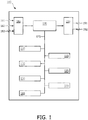
- Fig. 1 schematically shows a block diagram of an exemplary embodiment of the system 100 for segmenting an object in an image comprising:
- the exemplary embodiment of the system 100 further comprises:
- the first input connector 181 is arranged to receive data coming in from a data storage means such as, but not limited to, a hard disk, a magnetic tape, a flash memory, or an optical disk.
- the second input connector 182 is arranged to receive data coming in from a user input device such as, but not limited to, a mouse or a touch screen.
- the third input connector 183 is arranged to receive data coming in from a user input device such as a keyboard.
- the input connectors 181, 182 and 183 are connected to an input control unit 180.
- the first output connector 191 is arranged to output the data to a data storage means such as a hard disk, a magnetic tape, a flash memory, or an optical disk.
- the second output connector 192 is arranged to output the data to a display device.
- the output connectors 191 and 192 receive the respective data via an output control unit 190.
- a person skilled in the art will understand that there are many ways to connect input devices to the input connectors 181, 182 and 183 and the output devices to the output connectors 191 and 192 of the system 100. These ways comprise, but are not limited to, a wired and a wireless connection, a digital network such as, but not limited to, a Local Area Network (LAN) and a Wide Area Network (WAN), the Internet, a digital telephone network, and an analog telephone network.
- LAN Local Area Network
- WAN Wide Area Network
- the system 100 comprises a memory unit 170.
- the system 100 is arranged to receive input data from external devices via any of the input connectors 181, 182, and 183 and to store the received input data in the memory unit 170. Loading the input data into the memory unit 170 allows quick access to relevant data portions by the units of the system 100.
- the input data comprises the image, the first model for segmenting the object, and the plurality of models for segmenting the object.
- the memory unit 170 may be implemented by devices such as, but not limited to, a register file of a CPU, a cache memory, a Random Access Memory (RAM) chip, a Read Only Memory (ROM) chip, and/or a hard disk drive and a hard disk.
- RAM Random Access Memory
- ROM Read Only Memory
- the memory unit 170 may be further arranged to store the output data.
- the output data comprises the segmented object defined by the second model adapted to the image.
- the memory unit 170 may be also arranged to receive data from and/or deliver data to the units of the system 100 comprising the first adapter 110, the analyzer 115, the selector 120, the initializer 125, the second adapter 130, the control unit 160, and the user interface 165, via a memory bus 175.
- the memory unit 170 is further arranged to make the output data available to external devices via any of the output connectors 191 and 192. Storing data from the units of the system 100 in the memory unit 170 may advantageously improve performance of the units of the system 100 as well as the rate of transfer of the output data from the units of the system 100 to external devices.
- the system 100 comprises a control unit 160 for controlling the system 100.
- the control unit 160 may be arranged to receive control data from and provide control data to the units of the system 100.
- the selector 120 may be arranged to provide control data "the second model is selected" to the control unit 160, and the control unit 160 may be arranged to provide control data "initialize the second model" to the initializer 125.
- a control function may be implemented in another unit of the system 100.
- the system 100 comprises a user interface 165 for communication between a user and the system 100.
- the user interface 165 may be arranged to receive a user input for selecting the first model for segmenting the object and the plurality of models for segmenting the object.
- the user interface is adapted for displaying the adapted second model.
- the invention is used by a physician for segmenting the left atrium of the human heart in a 3-D CT image.
- the system 100 may be fully automated.
- the system 100 may be interactive, accepting user input.
- the user interface 165 of the system 100 may be arranged for displaying the selected second model and prompting the user for accepting or rejecting it.
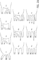
- Fig. 2A illustrates anatomical variability of the right side of the left atrium, defined by the number and position of draining pulmonary veins.
- the vein labels RUL, RML, RLL, BSRLL, and SSRLL stand for, respectively, right upper lobar, right middle lobar and right lower lobar, basilar segment RLL, and superior segment RLL.
- the vein patterns are labeled with labels R1, R2a, R2b, R2c, R3a, R3b, R3c, R4a, R4b, and R5.
- Fig. 2B shows a first model for segmenting the left atrium.
- the first model comprises a triangular mesh. Faces of triangular meshes are triangles. Image segmentation using models comprising triangular meshes is described in Ref. 1, for example, as well as in many other papers on segmentation based on deformable models easily available both in the patent and scientific literature. Some of the triangles of the first model are marked. The marked triangles may be used by the analyzer 115 for extracting features from the image.
- the first model is a simplified model of the left atrium. It does not include the right-side pulmonary veins.
- the simplified first model can be robustly adapted to the patient image by the first adaptation unit 110 of the system 100.
- a steered region growing process is started by the analyzer 115 of the system 100.
- Fig. 2C schematically illustrates an exemplary definition of a cone-like growth space based on marked triangles of the mesh of the first model for segmenting the left atrium.
- the analyzer 115 is arranged for determining the center 202 of the first model of the left atrium.
- the growth direction 204 is the axis of a conical volume with a boundary 206, defined by the centers 211 - 216 of marked triangles of the adapted first model.
- Said conical volume is defined by the smallest cone with the vertex placed at the center 202 and comprising all marked triangle centers 211 - 216.
- the growth direction 204 is the cone axis.
- the range R of region growing is a multiple of the mean distance from the center 202 of the first model to the first model surface 200.
- Fig. 2D illustrates detection of a bifurcation of a pulmonary vein draining into the left atrium, using region growing.
- the region growing starts at the seed point which is the center 202 of the first model of the left atrium.
- the front of the region growing may be, for example, a plane perpendicular to the growth direction 204 or a spherical cap defined by a sphere with the center at the center 202 of the adapted first model and the conical volume with the boundary 206.
- Fig. 2D shows five spherical fronts 221 - 215 and the boundaries 210 of the grown region.
- the boundaries 210 of the grown region represent walls of pulmonary veins draining into the left atrium. Each front is analyzed to determine its connectedness.
- Fig. 2D illustrates detection of a bifurcation of a pulmonary vein draining into the left atrium, using region growing.
- the region growing starts at the seed point which is the center 202 of the first model of the left atrium
- fronts 221 and 222 are connected and fronts 223.
- 224 and 225 are disconnected, each comprising two connected components.
- the analyzer is arranged to conclude that there is a bifurcation point in the pulmonary vain modeled by the boundary 210 of the grown region.
- the analyzer 115 may be arranged for detecting these other features.
- the analyzer 115 may be arranged to compute the curvature of the surface of the first model. Based on an analysis of the curvature, the analyzer 115 may be arranged to determine size and locations of blood vessel stems extending from a structure described by the adapted first model.
- the analyzer 115 may be arranged for fitting an ellipsoid to the adapted first model.
- a region growing method can be employed by the analyzer to extract further features from the image. The seed point, the direction, and/or the extent of the region growing may be determined based on the parameters of the fitted ellipsoid.
- the selector 120 is arranged for selecting the second model from the plurality of models for segmenting the left atrium.
- Fig. 3 shows exemplary models for segmenting the left atrium.
- Some of these models comprise different numbers of pulmonary veins and thus are topologically not equivalent to each other because there is no homeomorphism which transforms one model into another model with a different number of pulmonary veins. Therefore it is very important for the segmentation based on deformable models to select a suitable variant of the model of the left atrium which can be adapted to the image to segment the left atrium.
- the adaptation process is typically based on continuous deformations of the model surface and thus no pulmonary veins can be added to or removed from the left atrium model.
- the first model is simplified in the sense that it does not comprise the additional detail of the second model.
- the additional detail is a structural component of the model such as an additional tubular surface for segmenting a blood vessel connected to the object or additional vertices of the model mesh for modeling fine curvature variability of the model surface.
- the additional detail can be an additional term for describing interaction of the second model with the image or a new way of selecting image features for attracting the second model during adaptation to the image, determined based on the features extracted from the image by the analyzer 115.
- the second model is initialized by the initializer 125.
- the initialization may use information obtained from the adapted first model as well as information obtained from the features extracted from the image by the analyzer 115.
- the second adapter 130 is then arranged to adapt the initialized second model to the image.
- the system 100 may be redefine the units of the system and to redistribute their functions. For example, the same unit may be arranged to adapt first the first model and next the second model to the image.
- the analyzer 115 may be implemented by a number of coupled units, each performing an analysis task, e.g. region growing, connectivity check of the front of a grown region, etc.
- the units of the system 100 may be implemented using a processor. Normally, their functions are performed under the control of a software program product. During execution, the software program product is normally loaded into a memory, like a RAM, and executed from there. The program may be loaded from a background memory, such as a ROM, hard disk, or magnetic and/or optical storage, or may be loaded via a network like the Internet. Optionally, an application-specific integrated circuit may provide the described functionality.
- the method M begins with the step of adapting S10 a first model for segmenting the object to the image. After the first model is adapted to the image, the step of extracting S15 a feature from the image based on the adapted first model is performed. After extracting S15 the feature from the image, the step of selecting S20 a second model for segmenting the object based on the feature extracted from the image is performed, wherein the second model comprises additional detail of the object. After selecting S20 the second model, the method M continues by initializing S25 the second model based on the adapted first model and/or the feature extracted from the image. After initializing S25 the second model, the initialized second model is adapted to the image in the step of adapting S30 the second model to the image.
- a person skilled in the art may change the order of some steps or perform some steps concurrently using threading models, multi-processor systems or multiple processes without departing from the concept as intended by the present invention.
- two or more steps of the method M may be combined into one step.
- a step of the method M may be split into a plurality of steps.
- Fig. 5 schematically shows an exemplary embodiment of the image acquisition apparatus 500 employing the system 100 of the invention, said image acquisition apparatus 500 comprising an image acquisition unit 510 connected via an internal connection with the system 100, an input connector 501, and an output connector 502.
- This arrangement advantageously increases the capabilities of the image acquisition apparatus 500, providing said image acquisition apparatus 500 with advantageous capabilities of the system 100.
- Fig. 6 schematically shows an exemplary embodiment of the workstation 600.
- the workstation comprises a system bus 601.
- a processor 610, a memory 620, a disk input/output (I/O) adapter 630, and a user interface (UI) 640 are operatively connected to the system bus 601.
- a disk storage device 631 is operatively coupled to the disk I/O adapter 630.
- a keyboard 641, a mouse 642, and a display 643 are operatively coupled to the UI 640.
- the system 100 of the invention, implemented as a computer program, is stored in the disk storage device 631.
- the workstation 600 is arranged to load the program and input data into memory 620 and execute the program on the processor 610.
- the user can input information to the workstation 600, using the keyboard 641 and/or the mouse 642.
- the workstation is arranged to output information to the display device 643 and/or to the disk 631.
- a person skilled in the art will understand that there are numerous other embodiments of the workstation 600 known in the art and that the present embodiment serves the purpose of illustrating the invention and must not be interpreted as limiting the invention to this particular embodiment.
Description
- The invention relates to image segmentation and, more particularly, to image segmentation using deformable models.
- Model-based delineation of organs is an efficient and robust way to segment medical images. In this approach, a model of the organ is adapted to the image, thereby delineating the organ. Such methods were described, for example, in Jürgen Weese, Michael Kaus, Christian Lorenz, Steven Lobregt, Roel Truyen and Vladimir Pekar's Shape Constrained Deformable Models for 3D Medical Image Segmentation, Lecture Notes in Computer Science, 2001, Volume 2082/2001, pages 380-387, hereinafter referred to as Ref. 1, and many other papers co-authored by any of the authors of Ref. 1. However, known models are typically fairly rigid and thus their deformation during adaptation to the image is small. Therefore, this approach often fails when applied to segment images depicting organs with high shape variability, especially when the organ shape variants are topologically not equivalent. Examples of such organs include the left atrium of the heart having many variants comprising different numbers of pulmonary veins draining into it, or the kidneys having many different arterial feeding connections.
-
WO 2009/034499 A2 describes a system and method for segmentation of image data describing an object comprising a first and second object component, involving selecting a first component model of a plurality of first component models for adapting to the image data in order to delineate the first object component; selecting a second component model of a plurality of second component models for adapting to the image data in order to delineate the second object component; connecting the first and second component model; initializing the first and second component model in the image data volume; and adapting the first and second component model to the image data, thereby segmenting the image data. - It would be advantageous to have a system for image segmentation using deformable models to delineate organs with high anatomical variability.
- Thus, in an aspect, the invention provides a system for segmenting an object in an image as defined in
claim 1. The first model is simpler than the second model and thus easier to adapt to the image. Although the object segmented with the first model is typically incomplete, the adapted first model allows the analyzer to extract image features by, for example, providing an indication of the region where the features may be found. The extracted features help the system to select the second model for segmenting the object from a plurality of models for segmenting the object. Because the second model comprises the additional detail of the object, the segmentation result obtained using the second model is more complete than the segmentation result obtained using the first model. Advantageously, the adapted first model and/or the extracted features are used for initializing the second model. Initialization comprises placement of the second model in the image space, e.g. image volume in the case of 3-dimensional images. The initialization of the second model based on the adapted first model and/or the detected features improves the accuracy of the second model adaptation. - In an embodiment of the system, extracting of features is based on at least one of the following: a component of the first model such as a vertex of the first model mesh or a triangle of the first model triangular mesh, a landmark of the first model such as a cusp on the first model surface, and a geometric primitive fitted to the first model such as an axis, a contour, a plane, a polygon, an ellipse, a cylinder, a pyramid, a cube, or an ellipsoid.
- In an embodiment of the system, extracting a feature from the image comprises region growing steered by the adapted first model. Region growing may be used for detecting image features such as blood vessel walls and centerlines which help select and initialize the second model comprising the corresponding blood vessel fragments.
- In an embodiment of the system, the feature extracted from the image is one of the following: a feature-object such as a ring, a tube, a tube centerline, or a topological sphere with zero, one, two or three handles, and a property of a feature-object such as the diameter of a ring or the number of handles in a topological sphere with handles. A person skilled in the art will understand that a topological sphere is a class of shapes topologically equivalent, i.e. homeomorphic, to a sphere.
- In an embodiment of the system, the plurality of models for segmenting the object comprise topologically non-equivalent models. It is important that the selected second model, for example, a surface, is topologically equivalent to the segmented object, for example, a blood vessel wall surface, because it is impossible to properly segment the object using the second model which is topologically non-equivalent to the object. Some objects, such as the left atrium, may have topologically non-equivalent shapes. It is thus important that the plurality of models for modeling the left atrium comprise many topologically non-equivalent models describing topologically non-equivalent shapes of the atrium present in a population of patients.
- In a further aspect, the invention provides an image acquisition apparatus comprising a system according to the invention.
- In a further aspect, the invention provides a workstation comprising a system according to the invention.
- In a further aspect, the invention provides a method of segmenting an object in an image as defined in claim 9. In a further aspect, the invention provides a computer program product to be loaded by a computer arrangement, comprising instructions for segmenting an object in an image, the computer arrangement comprising a processing unit and a memory, the computer program product, after being loaded, providing said processing unit with the capability to carry out steps of the method according to the invention.
- It will be appreciated by those skilled in the art that two or more of the above-mentioned embodiments, implementations, and/or aspects of the invention may be combined in any way deemed useful.
- Modifications and variations of the image acquisition apparatus, of the workstation, of the method, and/or of the computer program product, which correspond to the described modifications and variations of the system or of the method, can be carried out by a person skilled in the art on the basis of the description.
- A person skilled in the art will appreciate that an image dataset in the claimed invention may be a 2-dimensional (2-D), 3-dimensional (3-D) or 4-dimensional (4-D) image dataset, acquired by various acquisition modalities such as, but not limited to, X-ray Imaging, Computed Tomography (CT), Magnetic Resonance Imaging (MRI), Ultrasound (US), Positron Emission Tomography (PET), Single Photon Emission Computed Tomography (SPECT), and Nuclear Medicine (NM).
- The invention is defined in the independent claims. Advantageous embodiments are defined in the dependent claims.
- These and other aspects of the invention will become apparent from and will be elucidated with respect to the implementations and embodiments described hereinafter and with reference to the accompanying drawings, wherein:
-
Fig. 1 shows a block diagram of an exemplary embodiment of the system; -
Fig. 2A illustrates anatomical variability of the left atrium; -
Fig. 2B shows a first model for segmenting the left atrium; -
Fig. 2C illustrates exemplary definitions of a cone-like growth space based on the first model for segmenting the left atrium; -
Fig. 2D illustrates detection of a bifurcation of a pulmonary vein draining into the left atrium, using region growing; -
Fig. 3 shows exemplary models for segmenting the left atrium; -
Fig. 4 shows a flowchart of exemplary implementations of the method; -
Fig. 5 schematically shows an exemplary embodiment of the image acquisition apparatus; and -
Fig. 6 schematically shows an exemplary embodiment of the workstation. - Identical reference numerals are used to denote similar parts throughout the Figures.
-
Fig. 1 schematically shows a block diagram of an exemplary embodiment of thesystem 100 for segmenting an object in an image comprising: - a
first adapter 110 for adapting a first model for segmenting the object to the image; - an
analyzer 115 for extracting a feature from the image based on the adapted first model; - a
selector 120 for selecting a second model for segmenting the object based on the feature extracted from the image, wherein the second model comprises additional detail of the object; - an
initializer 125 for initializing the second model based on the adapted first model and/or the feature extracted from the image; and - a
second adapter 130 for adapting the initialized second model to the image. - The exemplary embodiment of the
system 100 further comprises: - a
control unit 160 for controlling the work of thesystem 100; - a
user interface 165 for communication between the user and thesystem 100; and - a
memory unit 170 for storing data. - In an embodiment of the
system 100, there are threeinput connectors first input connector 181 is arranged to receive data coming in from a data storage means such as, but not limited to, a hard disk, a magnetic tape, a flash memory, or an optical disk. Thesecond input connector 182 is arranged to receive data coming in from a user input device such as, but not limited to, a mouse or a touch screen. Thethird input connector 183 is arranged to receive data coming in from a user input device such as a keyboard. Theinput connectors input control unit 180. - In an embodiment of the
system 100, there are twooutput connectors first output connector 191 is arranged to output the data to a data storage means such as a hard disk, a magnetic tape, a flash memory, or an optical disk. Thesecond output connector 192 is arranged to output the data to a display device. Theoutput connectors output control unit 190. - A person skilled in the art will understand that there are many ways to connect input devices to the
input connectors output connectors system 100. These ways comprise, but are not limited to, a wired and a wireless connection, a digital network such as, but not limited to, a Local Area Network (LAN) and a Wide Area Network (WAN), the Internet, a digital telephone network, and an analog telephone network. - In an embodiment of the
system 100, thesystem 100 comprises amemory unit 170. Thesystem 100 is arranged to receive input data from external devices via any of theinput connectors memory unit 170. Loading the input data into thememory unit 170 allows quick access to relevant data portions by the units of thesystem 100. The input data comprises the image, the first model for segmenting the object, and the plurality of models for segmenting the object. Thememory unit 170 may be implemented by devices such as, but not limited to, a register file of a CPU, a cache memory, a Random Access Memory (RAM) chip, a Read Only Memory (ROM) chip, and/or a hard disk drive and a hard disk. Thememory unit 170 may be further arranged to store the output data. The output data comprises the segmented object defined by the second model adapted to the image. Thememory unit 170 may be also arranged to receive data from and/or deliver data to the units of thesystem 100 comprising thefirst adapter 110, theanalyzer 115, theselector 120, theinitializer 125, thesecond adapter 130, thecontrol unit 160, and theuser interface 165, via amemory bus 175. Thememory unit 170 is further arranged to make the output data available to external devices via any of theoutput connectors system 100 in thememory unit 170 may advantageously improve performance of the units of thesystem 100 as well as the rate of transfer of the output data from the units of thesystem 100 to external devices. - In an embodiment of the
system 100, thesystem 100 comprises acontrol unit 160 for controlling thesystem 100. Thecontrol unit 160 may be arranged to receive control data from and provide control data to the units of thesystem 100. For example, after selecting the second model, theselector 120 may be arranged to provide control data "the second model is selected" to thecontrol unit 160, and thecontrol unit 160 may be arranged to provide control data "initialize the second model" to theinitializer 125. Alternatively, a control function may be implemented in another unit of thesystem 100. - In an embodiment of the
system 100, thesystem 100 comprises auser interface 165 for communication between a user and thesystem 100. Theuser interface 165 may be arranged to receive a user input for selecting the first model for segmenting the object and the plurality of models for segmenting the object. Next, the user interface is adapted for displaying the adapted second model. A person skilled in the art will understand that more functions may be advantageously implemented in theuser interface 165 of thesystem 100. - In an embodiment, the invention is used by a physician for segmenting the left atrium of the human heart in a 3-D CT image. The
system 100 may be fully automated. Alternatively, thesystem 100 may be interactive, accepting user input. For example, after selecting the second model from the plurality of models for segmenting the left atrium, theuser interface 165 of thesystem 100 may be arranged for displaying the selected second model and prompting the user for accepting or rejecting it. -
Fig. 2A illustrates anatomical variability of the right side of the left atrium, defined by the number and position of draining pulmonary veins. The vein labels RUL, RML, RLL, BSRLL, and SSRLL stand for, respectively, right upper lobar, right middle lobar and right lower lobar, basilar segment RLL, and superior segment RLL. The vein patterns are labeled with labels R1, R2a, R2b, R2c, R3a, R3b, R3c, R4a, R4b, and R5. -
Fig. 2B shows a first model for segmenting the left atrium. The first model comprises a triangular mesh. Faces of triangular meshes are triangles. Image segmentation using models comprising triangular meshes is described in Ref. 1, for example, as well as in many other papers on segmentation based on deformable models easily available both in the patent and scientific literature. Some of the triangles of the first model are marked. The marked triangles may be used by theanalyzer 115 for extracting features from the image. - The first model is a simplified model of the left atrium. It does not include the right-side pulmonary veins. The simplified first model can be robustly adapted to the patient image by the
first adaptation unit 110 of thesystem 100. - After adapting the first model to the image, a steered region growing process is started by the
analyzer 115 of thesystem 100.Fig. 2C schematically illustrates an exemplary definition of a cone-like growth space based on marked triangles of the mesh of the first model for segmenting the left atrium. Theanalyzer 115 is arranged for determining thecenter 202 of the first model of the left atrium. Thegrowth direction 204 is the axis of a conical volume with aboundary 206, defined by the centers 211 - 216 of marked triangles of the adapted first model. Said conical volume is defined by the smallest cone with the vertex placed at thecenter 202 and comprising all marked triangle centers 211 - 216. Thegrowth direction 204 is the cone axis. The range R of region growing is a multiple of the mean distance from thecenter 202 of the first model to thefirst model surface 200. -
Fig. 2D illustrates detection of a bifurcation of a pulmonary vein draining into the left atrium, using region growing. The region growing starts at the seed point which is thecenter 202 of the first model of the left atrium. The front of the region growing may be, for example, a plane perpendicular to thegrowth direction 204 or a spherical cap defined by a sphere with the center at thecenter 202 of the adapted first model and the conical volume with theboundary 206.Fig. 2D shows five spherical fronts 221 - 215 and theboundaries 210 of the grown region. Theboundaries 210 of the grown region represent walls of pulmonary veins draining into the left atrium. Each front is analyzed to determine its connectedness. InFig. 2D ,fronts fronts 223. 224 and 225 are disconnected, each comprising two connected components. Hence, the analyzer is arranged to conclude that there is a bifurcation point in the pulmonary vain modeled by theboundary 210 of the grown region. - A person skilled in the art will understand that there are many other features and that the
analyzer 115 may be arranged for detecting these other features. For example, theanalyzer 115 may be arranged to compute the curvature of the surface of the first model. Based on an analysis of the curvature, theanalyzer 115 may be arranged to determine size and locations of blood vessel stems extending from a structure described by the adapted first model. In yet another example, theanalyzer 115 may be arranged for fitting an ellipsoid to the adapted first model. Further, a region growing method can be employed by the analyzer to extract further features from the image. The seed point, the direction, and/or the extent of the region growing may be determined based on the parameters of the fitted ellipsoid. - Based on the detailed number and positions of the pulmonary veins extracted from the image on the basis of the first model, the
selector 120 is arranged for selecting the second model from the plurality of models for segmenting the left atrium.Fig. 3 shows exemplary models for segmenting the left atrium. Some of these models comprise different numbers of pulmonary veins and thus are topologically not equivalent to each other because there is no homeomorphism which transforms one model into another model with a different number of pulmonary veins. Therefore it is very important for the segmentation based on deformable models to select a suitable variant of the model of the left atrium which can be adapted to the image to segment the left atrium. The adaptation process is typically based on continuous deformations of the model surface and thus no pulmonary veins can be added to or removed from the left atrium model. - The first model is simplified in the sense that it does not comprise the additional detail of the second model. Typically, the additional detail is a structural component of the model such as an additional tubular surface for segmenting a blood vessel connected to the object or additional vertices of the model mesh for modeling fine curvature variability of the model surface. Alternatively, the additional detail can be an additional term for describing interaction of the second model with the image or a new way of selecting image features for attracting the second model during adaptation to the image, determined based on the features extracted from the image by the
analyzer 115. - After the
selector 120 of thesystem 100 selects a second model, the second model is initialized by theinitializer 125. Advantageously, the initialization may use information obtained from the adapted first model as well as information obtained from the features extracted from the image by theanalyzer 115. Thesecond adapter 130 is then arranged to adapt the initialized second model to the image. - Although the embodiments of the invention have been described with reference to the left atrium segmentation, a person skilled in the art will understand that the invention is useful for segmenting other objects as well, especially for segmenting objects existing in many anatomical or pathological variants with different dimensions and/or topology. Examples of such objects include, but are not limited to, coronary arteries and kidneys with their arterial feeding connections.
- Those skilled in the art will further understand that other embodiments of the
system 100 are also possible. It is possible, among other things, to redefine the units of the system and to redistribute their functions. For example, the same unit may be arranged to adapt first the first model and next the second model to the image. On the other hand, theanalyzer 115 may be implemented by a number of coupled units, each performing an analysis task, e.g. region growing, connectivity check of the front of a grown region, etc. Although the described embodiments apply to medical images, other applications of the system, not related to medical applications, are also possible. - The units of the
system 100 may be implemented using a processor. Normally, their functions are performed under the control of a software program product. During execution, the software program product is normally loaded into a memory, like a RAM, and executed from there. The program may be loaded from a background memory, such as a ROM, hard disk, or magnetic and/or optical storage, or may be loaded via a network like the Internet. Optionally, an application-specific integrated circuit may provide the described functionality. - An exemplary flowchart of the method M of segmenting an object in an image is schematically shown in
Fig. 4 . The method M begins with the step of adapting S10 a first model for segmenting the object to the image. After the first model is adapted to the image, the step of extracting S15 a feature from the image based on the adapted first model is performed. After extracting S15 the feature from the image, the step of selecting S20 a second model for segmenting the object based on the feature extracted from the image is performed, wherein the second model comprises additional detail of the object. After selecting S20 the second model, the method M continues by initializing S25 the second model based on the adapted first model and/or the feature extracted from the image. After initializing S25 the second model, the initialized second model is adapted to the image in the step of adapting S30 the second model to the image. - A person skilled in the art may change the order of some steps or perform some steps concurrently using threading models, multi-processor systems or multiple processes without departing from the concept as intended by the present invention. Optionally, two or more steps of the method M may be combined into one step. Optionally, a step of the method M may be split into a plurality of steps.
-
Fig. 5 schematically shows an exemplary embodiment of theimage acquisition apparatus 500 employing thesystem 100 of the invention, saidimage acquisition apparatus 500 comprising animage acquisition unit 510 connected via an internal connection with thesystem 100, aninput connector 501, and anoutput connector 502. This arrangement advantageously increases the capabilities of theimage acquisition apparatus 500, providing saidimage acquisition apparatus 500 with advantageous capabilities of thesystem 100. -
Fig. 6 schematically shows an exemplary embodiment of theworkstation 600. The workstation comprises asystem bus 601. Aprocessor 610, amemory 620, a disk input/output (I/O)adapter 630, and a user interface (UI) 640 are operatively connected to thesystem bus 601. Adisk storage device 631 is operatively coupled to the disk I/O adapter 630. Akeyboard 641, amouse 642, and adisplay 643 are operatively coupled to theUI 640. Thesystem 100 of the invention, implemented as a computer program, is stored in thedisk storage device 631. Theworkstation 600 is arranged to load the program and input data intomemory 620 and execute the program on theprocessor 610. The user can input information to theworkstation 600, using thekeyboard 641 and/or themouse 642. The workstation is arranged to output information to thedisplay device 643 and/or to thedisk 631. A person skilled in the art will understand that there are numerous other embodiments of theworkstation 600 known in the art and that the present embodiment serves the purpose of illustrating the invention and must not be interpreted as limiting the invention to this particular embodiment. - It should be noted that the above-mentioned embodiments illustrate rather than limit the invention and that those skilled in the art will be able to design alternative embodiments without departing from the scope of the appended claims. In the claims, any reference signs placed between parentheses shall not be construed as limiting the claim. The word "comprising" does not exclude the presence of elements or steps not listed in a claim or in the description. The word "a" or "an" preceding an element does not exclude the presence of a plurality of such elements. The invention can be implemented by means of hardware comprising several distinct elements and by means of a programmed computer. In the system claims enumerating several units, several of these units can be embodied by one and the same record of hardware or software. The use of the words first, second, third, etc., does not indicate any ordering. These words are to be interpreted as names.
Claims (10)
- A system (100) for segmenting an object in a medical image comprising:- a first adapter (110) for adapting a first deformable model for segmenting the object to the medical image;- an analyzer (115) for extracting a feature from the image based on a steered region growing process which growth space is limited based on marked triangles of the mesh of the first deformable model and the center of the adapted first deformable model;- a selector (120) for selecting a second deformable model for segmenting the object based on the feature extracted from the medical image, wherein the second deformable model comprises additional detail of the object;- an initializer (125) for initializing the second deformable model based on the adapted first deformable model and/or the feature extracted from the medical image; and- a second adapter (130) for adapting the initialized second deformable model to the medical image.
- A system (100) as claimed in claim 1, wherein extracting of features is based on at least one of the following:- a component of the first deformable model;- a landmark of the first deformable model; and- a geometric primitive fitted to the first deformable model such as an axis, a contour, a plane, a polygon, an ellipse, a cylinder, a pyramid, a cube, or an ellipsoid.
- A system (100) as claimed in claim 1, wherein the feature extracted from the medical image is one of the following:- a feature-object such as a ring, a tube, a tube centerline, or a sphere with zero, one, two or three handles; and- a property of a feature-object such as the diameter of a ring or the number of handles in a topological sphere with handles.
- A system (100) as claimed in claim 1, wherein the plurality of deformable models for segmenting the object comprises topologically non-equivalent models.
- A system (100) as claimed in claim 1, wherein the first and second deformable models are left atrium models.
- A system (100) as claimed in claim 1, wherein the first and second deformable models are kidney models.
- A medical image acquisition apparatus (500) comprising a system (100) as claimed in claim 1.
- A workstation (600) comprising a system (100) as claimed in claim 1.
- A method (M) of segmenting an object in a medical image comprising the steps of:- adapting (S10) a first deformable model for segmenting the object to the medical image;- extracting (S15) a feature from the image based on a steered region growing process which growth space is limited based on marked triangles of the mesh of the first deformable model and the center of the adapted first deformable model;- selecting (S20) a second deformable model for segmenting the object based on the feature extracted from the medical image, wherein the second deformable model comprises additional detail of the object;- initializing (S25) the second deformable model based on the adapted first deformable model and/or the feature extracted from the medical image; and- adapting (S30) the initialized second deformable model to the medical image.
- A computer program product to be loaded by a computer arrangement, comprising instructions for segmenting an object in a medical image, the computer arrangement comprising a processing unit and a memory, the computer program product, after being loaded, providing said processing unit with the capability to carry out steps of a method as claimed in claim 9.
Priority Applications (2)
| Application Number | Priority Date | Filing Date | Title |
|---|---|---|---|
| EP17171640.0A EP3244370B1 (en) | 2010-09-17 | 2011-09-13 | Choosing anatomical variant model for image segmentation |
| EP11764333.8A EP2617010B1 (en) | 2010-09-17 | 2011-09-13 | Choosing anatomical variant model for image segmentation |
Applications Claiming Priority (3)
| Application Number | Priority Date | Filing Date | Title |
|---|---|---|---|
| EP10177387 | 2010-09-17 | ||
| EP11764333.8A EP2617010B1 (en) | 2010-09-17 | 2011-09-13 | Choosing anatomical variant model for image segmentation |
| PCT/IB2011/053991 WO2012035488A1 (en) | 2010-09-17 | 2011-09-13 | Choosing anatomical variant model for image segmentation |
Related Child Applications (2)
| Application Number | Title | Priority Date | Filing Date |
|---|---|---|---|
| EP17171640.0A Division-Into EP3244370B1 (en) | 2010-09-17 | 2011-09-13 | Choosing anatomical variant model for image segmentation |
| EP17171640.0A Division EP3244370B1 (en) | 2010-09-17 | 2011-09-13 | Choosing anatomical variant model for image segmentation |
Publications (2)
| Publication Number | Publication Date |
|---|---|
| EP2617010A1 EP2617010A1 (en) | 2013-07-24 |
| EP2617010B1 true EP2617010B1 (en) | 2017-07-26 |
Family
ID=44735998
Family Applications (2)
| Application Number | Title | Priority Date | Filing Date |
|---|---|---|---|
| EP17171640.0A Active EP3244370B1 (en) | 2010-09-17 | 2011-09-13 | Choosing anatomical variant model for image segmentation |
| EP11764333.8A Active EP2617010B1 (en) | 2010-09-17 | 2011-09-13 | Choosing anatomical variant model for image segmentation |
Family Applications Before (1)
| Application Number | Title | Priority Date | Filing Date |
|---|---|---|---|
| EP17171640.0A Active EP3244370B1 (en) | 2010-09-17 | 2011-09-13 | Choosing anatomical variant model for image segmentation |
Country Status (7)
| Country | Link |
|---|---|
| US (1) | US9367913B2 (en) |
| EP (2) | EP3244370B1 (en) |
| JP (1) | JP5897012B2 (en) |
| CN (1) | CN103098092B (en) |
| BR (1) | BR112013006095A2 (en) |
| RU (1) | RU2609084C2 (en) |
| WO (1) | WO2012035488A1 (en) |
Families Citing this family (1)
| Publication number | Priority date | Publication date | Assignee | Title |
|---|---|---|---|---|
| US10319090B2 (en) * | 2014-05-14 | 2019-06-11 | Koninklijke Philips N.V. | Acquisition-orientation-dependent features for model-based segmentation of ultrasound images |
Family Cites Families (21)
| Publication number | Priority date | Publication date | Assignee | Title |
|---|---|---|---|---|
| RU2132061C1 (en) * | 1997-02-19 | 1999-06-20 | ЗАО "Медицинские компьютерные системы" | Method for performing automatic adaptive cell segmentation and recognition on cytological preparation images |
| DE10144004A1 (en) * | 2001-09-07 | 2003-03-27 | Philips Corp Intellectual Pty | Method of taking three-dimensional measurements for use in measuring physical properties in medical applications, by overlaying three dimensional images |
| US7397937B2 (en) * | 2001-11-23 | 2008-07-08 | R2 Technology, Inc. | Region growing in anatomical images |
| JP2005521502A (en) * | 2002-04-03 | 2005-07-21 | セガミ エス.エー.アール.エル. | Overlay of chest and abdominal image modalities |
| US20060008143A1 (en) * | 2002-10-16 | 2006-01-12 | Roel Truyen | Hierachical image segmentation |
| JP2006506164A (en) * | 2002-11-20 | 2006-02-23 | コーニンクレッカ フィリップス エレクトロニクス エヌ ヴィ | An image processing system that automatically adapts a 3D mesh model to the 3D surface of an object |
| EP1597701A1 (en) * | 2003-02-27 | 2005-11-23 | Agency for Science, Technology and Research | Method and apparatus for extracting cerebral ventricular system from images |
| CN1296699C (en) | 2003-12-19 | 2007-01-24 | 武汉大学 | Microscopic multispectral marrow and its peripheral blood cell auto-analyzing instrument and method |
| US7957572B2 (en) * | 2005-02-11 | 2011-06-07 | Koninklijke Philips Electronics N.V. | Image processing device and method |
| RU2009102657A (en) * | 2006-06-28 | 2010-08-10 | Конинклейке Филипс Электроникс Н.В. (Nl) | SEGMENTATION OF THE IMAGE BASED ON THE VARIABLE RESOLUTION MODEL |
| WO2008018014A2 (en) * | 2006-08-11 | 2008-02-14 | Koninklijke Philips Electronics N.V. | Anatomy-related image-context-dependent applications for efficient diagnosis |
| CN101541242B (en) | 2006-11-30 | 2012-06-13 | 皇家飞利浦电子股份有限公司 | Visualizing a vascular structure |
| US8050473B2 (en) * | 2007-02-13 | 2011-11-01 | The Trustees Of The University Of Pennsylvania | Segmentation method using an oriented active shape model |
| US9275190B2 (en) | 2007-04-23 | 2016-03-01 | Siemens Aktiengesellschaft | Method and system for generating a four-chamber heart model |
| WO2009034499A2 (en) * | 2007-09-13 | 2009-03-19 | Philips Intellectual Property & Standards Gmbh | Flexible 'plug-and-play' medical image segmentation |
| US8698795B2 (en) | 2008-01-24 | 2014-04-15 | Koninklijke Philips N.V. | Interactive image segmentation |
| US8064675B2 (en) * | 2008-01-30 | 2011-11-22 | Carestream Health, Inc. | Computer-aided tubing detection |
| EP2238573A2 (en) | 2008-01-31 | 2010-10-13 | Koninklijke Philips Electronics N.V. | Automatic 3-d segmentation of the short-axis late-enhancement cardiac mri |
| CN101971213A (en) * | 2008-02-29 | 2011-02-09 | 新加坡科技研究局 | A method and system for anatomy structure segmentation and modeling in an image |
| US8331648B2 (en) | 2008-10-03 | 2012-12-11 | Patent Store Llc | Making sealant containing twist-on wire connectors |
| US8577130B2 (en) * | 2009-03-16 | 2013-11-05 | Siemens Medical Solutions Usa, Inc. | Hierarchical deformable model for image segmentation |
-
2011
- 2011-09-13 US US13/823,472 patent/US9367913B2/en active Active
- 2011-09-13 EP EP17171640.0A patent/EP3244370B1/en active Active
- 2011-09-13 JP JP2013528804A patent/JP5897012B2/en active Active
- 2011-09-13 WO PCT/IB2011/053991 patent/WO2012035488A1/en active Application Filing
- 2011-09-13 RU RU2013117435A patent/RU2609084C2/en active
- 2011-09-13 BR BR112013006095A patent/BR112013006095A2/en not_active IP Right Cessation
- 2011-09-13 CN CN201180044254.8A patent/CN103098092B/en active Active
- 2011-09-13 EP EP11764333.8A patent/EP2617010B1/en active Active
Non-Patent Citations (1)
| Title |
|---|
| None * |
Also Published As
| Publication number | Publication date |
|---|---|
| RU2013117435A (en) | 2014-10-27 |
| WO2012035488A1 (en) | 2012-03-22 |
| JP2013537078A (en) | 2013-09-30 |
| EP2617010A1 (en) | 2013-07-24 |
| RU2609084C2 (en) | 2017-01-30 |
| US20130286013A1 (en) | 2013-10-31 |
| US9367913B2 (en) | 2016-06-14 |
| JP5897012B2 (en) | 2016-03-30 |
| EP3244370A1 (en) | 2017-11-15 |
| BR112013006095A2 (en) | 2019-09-24 |
| CN103098092B (en) | 2016-05-11 |
| EP3244370B1 (en) | 2020-08-19 |
| CN103098092A (en) | 2013-05-08 |
Similar Documents
| Publication | Publication Date | Title |
|---|---|---|
| US7995810B2 (en) | System and methods for image segmentation in n-dimensional space | |
| US8358819B2 (en) | System and methods for image segmentation in N-dimensional space | |
| EP2074585B1 (en) | Model-based coronary centerline localization | |
| Saha et al. | A survey on skeletonization algorithms and their applications | |
| US8571278B2 (en) | System and methods for multi-object multi-surface segmentation | |
| US9275190B2 (en) | Method and system for generating a four-chamber heart model | |
| US8073227B2 (en) | System and method for geometric modeling of tubular structures | |
| US20170258433A1 (en) | Method and System for Extracting Centerline Representation of Vascular Structures in Medical Images Via Optimal Paths in Computational Flow Fields | |
| US8126232B2 (en) | System and method for 3D vessel segmentation with minimal cuts | |
| WO2021244661A1 (en) | Method and system for determining blood vessel information in image | |
| US10210612B2 (en) | Method and system for machine learning based estimation of anisotropic vessel orientation tensor | |
| US20070109299A1 (en) | Surface-based characteristic path generation | |
| JP6505124B2 (en) | Automatic contour extraction system and method in adaptive radiation therapy | |
| RU2669680C2 (en) | View classification-based model initialisation | |
| US20060210158A1 (en) | Object-specific segmentation | |
| US9129387B2 (en) | Progressive model-based adaptation | |
| EP2617010B1 (en) | Choosing anatomical variant model for image segmentation | |
| EP2279489A2 (en) | Mesh collision avoidance | |
| Goyal et al. | MRI image based patient specific computational model reconstruction of the left ventricle cavity and myocardium | |
| Medina et al. | Left ventricle myocardium segmentation in multi-slice computerized tomography | |
| WO2008152555A2 (en) | Anatomy-driven image data segmentation | |
| Meyer et al. | A multi-modality segmentation framework: application to fully automatic heart segmentation | |
| WO2009034499A2 (en) | Flexible 'plug-and-play' medical image segmentation | |
| Sonka et al. | System and methods for multi-object multi-surface segmentation | |
| MINH | Atlas-assisted segmentation of hippocampus |
Legal Events
| Date | Code | Title | Description |
|---|---|---|---|
| PUAI | Public reference made under article 153(3) epc to a published international application that has entered the european phase |
Free format text: ORIGINAL CODE: 0009012 |
|
| 17P | Request for examination filed |
Effective date: 20130417 |
|
| AK | Designated contracting states |
Kind code of ref document: A1 Designated state(s): AL AT BE BG CH CY CZ DE DK EE ES FI FR GB GR HR HU IE IS IT LI LT LU LV MC MK MT NL NO PL PT RO RS SE SI SK SM TR |
|
| RAP1 | Party data changed (applicant data changed or rights of an application transferred) |
Owner name: KONINKLIJKE PHILIPS N.V. Owner name: PHILIPS INTELLECTUAL PROPERTY & STANDARDS GMBH |
|
| DAX | Request for extension of the european patent (deleted) | ||
| 17Q | First examination report despatched |
Effective date: 20140407 |
|
| REG | Reference to a national code |
Ref country code: DE Ref legal event code: R079 Ref document number: 602011039959 Country of ref document: DE Free format text: PREVIOUS MAIN CLASS: G06T0007000000 Ipc: G06T0007120000 |
|
| GRAP | Despatch of communication of intention to grant a patent |
Free format text: ORIGINAL CODE: EPIDOSNIGR1 |
|
| RIC1 | Information provided on ipc code assigned before grant |
Ipc: G06T 7/00 20170101ALI20170126BHEP Ipc: G06T 7/12 20170101AFI20170126BHEP Ipc: G06T 15/08 20110101ALI20170126BHEP Ipc: G06T 17/00 20060101ALI20170126BHEP Ipc: G06T 7/149 20170101ALI20170126BHEP |
|
| INTG | Intention to grant announced |
Effective date: 20170213 |
|
| RAP1 | Party data changed (applicant data changed or rights of an application transferred) |
Owner name: KONINKLIJKE PHILIPS ELECTRONICS N.V. Owner name: PHILIPS INTELLECTUAL PROPERTY & STANDARDS GMBH |
|
| GRAS | Grant fee paid |
Free format text: ORIGINAL CODE: EPIDOSNIGR3 |
|
| GRAA | (expected) grant |
Free format text: ORIGINAL CODE: 0009210 |
|
| AK | Designated contracting states |
Kind code of ref document: B1 Designated state(s): AL AT BE BG CH CY CZ DE DK EE ES FI FR GB GR HR HU IE IS IT LI LT LU LV MC MK MT NL NO PL PT RO RS SE SI SK SM TR |
|
| REG | Reference to a national code |
Ref country code: GB Ref legal event code: FG4D |
|
| REG | Reference to a national code |
Ref country code: CH Ref legal event code: EP |
|
| REG | Reference to a national code |
Ref country code: AT Ref legal event code: REF Ref document number: 912944 Country of ref document: AT Kind code of ref document: T Effective date: 20170815 |
|
| REG | Reference to a national code |
Ref country code: IE Ref legal event code: FG4D |
|
| REG | Reference to a national code |
Ref country code: DE Ref legal event code: R096 Ref document number: 602011039959 Country of ref document: DE |
|
| REG | Reference to a national code |
Ref country code: FR Ref legal event code: PLFP Year of fee payment: 7 Ref country code: DE Ref legal event code: R084 Ref document number: 602011039959 Country of ref document: DE |
|
| REG | Reference to a national code |
Ref country code: GB Ref legal event code: 746 Effective date: 20170920 |
|
| REG | Reference to a national code |
Ref country code: NL Ref legal event code: MP Effective date: 20170726 |
|
| REG | Reference to a national code |
Ref country code: LT Ref legal event code: MG4D |
|
| REG | Reference to a national code |
Ref country code: AT Ref legal event code: MK05 Ref document number: 912944 Country of ref document: AT Kind code of ref document: T Effective date: 20170726 |
|
| PG25 | Lapsed in a contracting state [announced via postgrant information from national office to epo] |
Ref country code: SE Free format text: LAPSE BECAUSE OF FAILURE TO SUBMIT A TRANSLATION OF THE DESCRIPTION OR TO PAY THE FEE WITHIN THE PRESCRIBED TIME-LIMIT Effective date: 20170726 Ref country code: LT Free format text: LAPSE BECAUSE OF FAILURE TO SUBMIT A TRANSLATION OF THE DESCRIPTION OR TO PAY THE FEE WITHIN THE PRESCRIBED TIME-LIMIT Effective date: 20170726 Ref country code: NL Free format text: LAPSE BECAUSE OF FAILURE TO SUBMIT A TRANSLATION OF THE DESCRIPTION OR TO PAY THE FEE WITHIN THE PRESCRIBED TIME-LIMIT Effective date: 20170726 Ref country code: HR Free format text: LAPSE BECAUSE OF FAILURE TO SUBMIT A TRANSLATION OF THE DESCRIPTION OR TO PAY THE FEE WITHIN THE PRESCRIBED TIME-LIMIT Effective date: 20170726 Ref country code: AT Free format text: LAPSE BECAUSE OF FAILURE TO SUBMIT A TRANSLATION OF THE DESCRIPTION OR TO PAY THE FEE WITHIN THE PRESCRIBED TIME-LIMIT Effective date: 20170726 Ref country code: FI Free format text: LAPSE BECAUSE OF FAILURE TO SUBMIT A TRANSLATION OF THE DESCRIPTION OR TO PAY THE FEE WITHIN THE PRESCRIBED TIME-LIMIT Effective date: 20170726 Ref country code: NO Free format text: LAPSE BECAUSE OF FAILURE TO SUBMIT A TRANSLATION OF THE DESCRIPTION OR TO PAY THE FEE WITHIN THE PRESCRIBED TIME-LIMIT Effective date: 20171026 |
|
| PG25 | Lapsed in a contracting state [announced via postgrant information from national office to epo] |
Ref country code: BG Free format text: LAPSE BECAUSE OF FAILURE TO SUBMIT A TRANSLATION OF THE DESCRIPTION OR TO PAY THE FEE WITHIN THE PRESCRIBED TIME-LIMIT Effective date: 20171026 Ref country code: GR Free format text: LAPSE BECAUSE OF FAILURE TO SUBMIT A TRANSLATION OF THE DESCRIPTION OR TO PAY THE FEE WITHIN THE PRESCRIBED TIME-LIMIT Effective date: 20171027 Ref country code: IS Free format text: LAPSE BECAUSE OF FAILURE TO SUBMIT A TRANSLATION OF THE DESCRIPTION OR TO PAY THE FEE WITHIN THE PRESCRIBED TIME-LIMIT Effective date: 20171126 Ref country code: LV Free format text: LAPSE BECAUSE OF FAILURE TO SUBMIT A TRANSLATION OF THE DESCRIPTION OR TO PAY THE FEE WITHIN THE PRESCRIBED TIME-LIMIT Effective date: 20170726 Ref country code: PL Free format text: LAPSE BECAUSE OF FAILURE TO SUBMIT A TRANSLATION OF THE DESCRIPTION OR TO PAY THE FEE WITHIN THE PRESCRIBED TIME-LIMIT Effective date: 20170726 Ref country code: RS Free format text: LAPSE BECAUSE OF FAILURE TO SUBMIT A TRANSLATION OF THE DESCRIPTION OR TO PAY THE FEE WITHIN THE PRESCRIBED TIME-LIMIT Effective date: 20170726 Ref country code: ES Free format text: LAPSE BECAUSE OF FAILURE TO SUBMIT A TRANSLATION OF THE DESCRIPTION OR TO PAY THE FEE WITHIN THE PRESCRIBED TIME-LIMIT Effective date: 20170726 |
|
| REG | Reference to a national code |
Ref country code: DE Ref legal event code: R081 Ref document number: 602011039959 Country of ref document: DE Owner name: PHILIPS GMBH, DE Free format text: FORMER OWNER: PHILIPS INTELLECTUAL PROPERTY & STANDARDS GMBH, 20099 HAMBURG, DE |
|
| PG25 | Lapsed in a contracting state [announced via postgrant information from national office to epo] |
Ref country code: DK Free format text: LAPSE BECAUSE OF FAILURE TO SUBMIT A TRANSLATION OF THE DESCRIPTION OR TO PAY THE FEE WITHIN THE PRESCRIBED TIME-LIMIT Effective date: 20170726 Ref country code: RO Free format text: LAPSE BECAUSE OF FAILURE TO SUBMIT A TRANSLATION OF THE DESCRIPTION OR TO PAY THE FEE WITHIN THE PRESCRIBED TIME-LIMIT Effective date: 20170726 Ref country code: CZ Free format text: LAPSE BECAUSE OF FAILURE TO SUBMIT A TRANSLATION OF THE DESCRIPTION OR TO PAY THE FEE WITHIN THE PRESCRIBED TIME-LIMIT Effective date: 20170726 |
|
| REG | Reference to a national code |
Ref country code: CH Ref legal event code: PL Ref country code: DE Ref legal event code: R097 Ref document number: 602011039959 Country of ref document: DE |
|
| PG25 | Lapsed in a contracting state [announced via postgrant information from national office to epo] |
Ref country code: IT Free format text: LAPSE BECAUSE OF FAILURE TO SUBMIT A TRANSLATION OF THE DESCRIPTION OR TO PAY THE FEE WITHIN THE PRESCRIBED TIME-LIMIT Effective date: 20170726 Ref country code: SM Free format text: LAPSE BECAUSE OF FAILURE TO SUBMIT A TRANSLATION OF THE DESCRIPTION OR TO PAY THE FEE WITHIN THE PRESCRIBED TIME-LIMIT Effective date: 20170726 Ref country code: MC Free format text: LAPSE BECAUSE OF FAILURE TO SUBMIT A TRANSLATION OF THE DESCRIPTION OR TO PAY THE FEE WITHIN THE PRESCRIBED TIME-LIMIT Effective date: 20170726 Ref country code: EE Free format text: LAPSE BECAUSE OF FAILURE TO SUBMIT A TRANSLATION OF THE DESCRIPTION OR TO PAY THE FEE WITHIN THE PRESCRIBED TIME-LIMIT Effective date: 20170726 Ref country code: SK Free format text: LAPSE BECAUSE OF FAILURE TO SUBMIT A TRANSLATION OF THE DESCRIPTION OR TO PAY THE FEE WITHIN THE PRESCRIBED TIME-LIMIT Effective date: 20170726 |
|
| PLBE | No opposition filed within time limit |
Free format text: ORIGINAL CODE: 0009261 |
|
| STAA | Information on the status of an ep patent application or granted ep patent |
Free format text: STATUS: NO OPPOSITION FILED WITHIN TIME LIMIT |
|
| REG | Reference to a national code |
Ref country code: IE Ref legal event code: MM4A |
|
| REG | Reference to a national code |
Ref country code: BE Ref legal event code: MM Effective date: 20170930 |
|
| PG25 | Lapsed in a contracting state [announced via postgrant information from national office to epo] |
Ref country code: LU Free format text: LAPSE BECAUSE OF NON-PAYMENT OF DUE FEES Effective date: 20170913 |
|
| 26N | No opposition filed |
Effective date: 20180430 |
|
| PG25 | Lapsed in a contracting state [announced via postgrant information from national office to epo] |
Ref country code: IE Free format text: LAPSE BECAUSE OF NON-PAYMENT OF DUE FEES Effective date: 20170913 Ref country code: LI Free format text: LAPSE BECAUSE OF NON-PAYMENT OF DUE FEES Effective date: 20170930 Ref country code: CH Free format text: LAPSE BECAUSE OF NON-PAYMENT OF DUE FEES Effective date: 20170930 |
|
| PG25 | Lapsed in a contracting state [announced via postgrant information from national office to epo] |
Ref country code: BE Free format text: LAPSE BECAUSE OF NON-PAYMENT OF DUE FEES Effective date: 20170930 Ref country code: SI Free format text: LAPSE BECAUSE OF FAILURE TO SUBMIT A TRANSLATION OF THE DESCRIPTION OR TO PAY THE FEE WITHIN THE PRESCRIBED TIME-LIMIT Effective date: 20170726 |
|
| PG25 | Lapsed in a contracting state [announced via postgrant information from national office to epo] |
Ref country code: MT Free format text: LAPSE BECAUSE OF NON-PAYMENT OF DUE FEES Effective date: 20170913 |
|
| REG | Reference to a national code |
Ref country code: FR Ref legal event code: PLFP Year of fee payment: 8 |
|
| PG25 | Lapsed in a contracting state [announced via postgrant information from national office to epo] |
Ref country code: HU Free format text: LAPSE BECAUSE OF FAILURE TO SUBMIT A TRANSLATION OF THE DESCRIPTION OR TO PAY THE FEE WITHIN THE PRESCRIBED TIME-LIMIT; INVALID AB INITIO Effective date: 20110913 |
|
| PG25 | Lapsed in a contracting state [announced via postgrant information from national office to epo] |
Ref country code: CY Free format text: LAPSE BECAUSE OF NON-PAYMENT OF DUE FEES Effective date: 20170726 |
|
| PG25 | Lapsed in a contracting state [announced via postgrant information from national office to epo] |
Ref country code: MK Free format text: LAPSE BECAUSE OF FAILURE TO SUBMIT A TRANSLATION OF THE DESCRIPTION OR TO PAY THE FEE WITHIN THE PRESCRIBED TIME-LIMIT Effective date: 20170726 |
|
| PG25 | Lapsed in a contracting state [announced via postgrant information from national office to epo] |
Ref country code: TR Free format text: LAPSE BECAUSE OF FAILURE TO SUBMIT A TRANSLATION OF THE DESCRIPTION OR TO PAY THE FEE WITHIN THE PRESCRIBED TIME-LIMIT Effective date: 20170726 |
|
| PG25 | Lapsed in a contracting state [announced via postgrant information from national office to epo] |
Ref country code: PT Free format text: LAPSE BECAUSE OF FAILURE TO SUBMIT A TRANSLATION OF THE DESCRIPTION OR TO PAY THE FEE WITHIN THE PRESCRIBED TIME-LIMIT Effective date: 20170726 |
|
| PG25 | Lapsed in a contracting state [announced via postgrant information from national office to epo] |
Ref country code: AL Free format text: LAPSE BECAUSE OF FAILURE TO SUBMIT A TRANSLATION OF THE DESCRIPTION OR TO PAY THE FEE WITHIN THE PRESCRIBED TIME-LIMIT Effective date: 20170726 |
|
| PGFP | Annual fee paid to national office [announced via postgrant information from national office to epo] |
Ref country code: GB Payment date: 20220920 Year of fee payment: 12 Ref country code: DE Payment date: 20220628 Year of fee payment: 12 |
|
| PGFP | Annual fee paid to national office [announced via postgrant information from national office to epo] |
Ref country code: FR Payment date: 20220926 Year of fee payment: 12 |