EP2616967B1 - System including a middleware machine environment - Google Patents
System including a middleware machine environment Download PDFInfo
- Publication number
- EP2616967B1 EP2616967B1 EP11764902.0A EP11764902A EP2616967B1 EP 2616967 B1 EP2616967 B1 EP 2616967B1 EP 11764902 A EP11764902 A EP 11764902A EP 2616967 B1 EP2616967 B1 EP 2616967B1
- Authority
- EP
- European Patent Office
- Prior art keywords
- application server
- cluster
- session
- data
- muxer
- Prior art date
- Legal status (The legal status is an assumption and is not a legal conclusion. Google has not performed a legal analysis and makes no representation as to the accuracy of the status listed.)
- Active
Links
Images


Classifications
-
- G—PHYSICS
- G06—COMPUTING OR CALCULATING; COUNTING
- G06F—ELECTRIC DIGITAL DATA PROCESSING
- G06F16/00—Information retrieval; Database structures therefor; File system structures therefor
- G06F16/20—Information retrieval; Database structures therefor; File system structures therefor of structured data, e.g. relational data
-
- G—PHYSICS
- G06—COMPUTING OR CALCULATING; COUNTING
- G06F—ELECTRIC DIGITAL DATA PROCESSING
- G06F15/00—Digital computers in general; Data processing equipment in general
- G06F15/16—Combinations of two or more digital computers each having at least an arithmetic unit, a program unit and a register, e.g. for a simultaneous processing of several programs
- G06F15/163—Interprocessor communication
- G06F15/173—Interprocessor communication using an interconnection network, e.g. matrix, shuffle, pyramid, star, snowflake
- G06F15/17306—Intercommunication techniques
- G06F15/17318—Parallel communications techniques, e.g. gather, scatter, reduce, roadcast, multicast, all to all
-
- G—PHYSICS
- G06—COMPUTING OR CALCULATING; COUNTING
- G06F—ELECTRIC DIGITAL DATA PROCESSING
- G06F16/00—Information retrieval; Database structures therefor; File system structures therefor
- G06F16/20—Information retrieval; Database structures therefor; File system structures therefor of structured data, e.g. relational data
- G06F16/23—Updating
- G06F16/2358—Change logging, detection, and notification
-
- G—PHYSICS
- G06—COMPUTING OR CALCULATING; COUNTING
- G06F—ELECTRIC DIGITAL DATA PROCESSING
- G06F16/00—Information retrieval; Database structures therefor; File system structures therefor
- G06F16/20—Information retrieval; Database structures therefor; File system structures therefor of structured data, e.g. relational data
- G06F16/27—Replication, distribution or synchronisation of data between databases or within a distributed database system; Distributed database system architectures therefor
- G06F16/278—Data partitioning, e.g. horizontal or vertical partitioning
-
- H—ELECTRICITY
- H04—ELECTRIC COMMUNICATION TECHNIQUE
- H04L—TRANSMISSION OF DIGITAL INFORMATION, e.g. TELEGRAPHIC COMMUNICATION
- H04L41/00—Arrangements for maintenance, administration or management of data switching networks, e.g. of packet switching networks
- H04L41/04—Network management architectures or arrangements
- H04L41/042—Network management architectures or arrangements comprising distributed management centres cooperatively managing the network
-
- H—ELECTRICITY
- H04—ELECTRIC COMMUNICATION TECHNIQUE
- H04L—TRANSMISSION OF DIGITAL INFORMATION, e.g. TELEGRAPHIC COMMUNICATION
- H04L41/00—Arrangements for maintenance, administration or management of data switching networks, e.g. of packet switching networks
- H04L41/06—Management of faults, events, alarms or notifications
- H04L41/0686—Additional information in the notification, e.g. enhancement of specific meta-data
-
- H—ELECTRICITY
- H04—ELECTRIC COMMUNICATION TECHNIQUE
- H04L—TRANSMISSION OF DIGITAL INFORMATION, e.g. TELEGRAPHIC COMMUNICATION
- H04L49/00—Packet switching elements
- H04L49/35—Switches specially adapted for specific applications
- H04L49/356—Switches specially adapted for specific applications for storage area networks
- H04L49/358—Infiniband Switches
-
- H—ELECTRICITY
- H04—ELECTRIC COMMUNICATION TECHNIQUE
- H04L—TRANSMISSION OF DIGITAL INFORMATION, e.g. TELEGRAPHIC COMMUNICATION
- H04L67/00—Network arrangements or protocols for supporting network services or applications
- H04L67/01—Protocols
- H04L67/02—Protocols based on web technology, e.g. hypertext transfer protocol [HTTP]
-
- H—ELECTRICITY
- H04—ELECTRIC COMMUNICATION TECHNIQUE
- H04L—TRANSMISSION OF DIGITAL INFORMATION, e.g. TELEGRAPHIC COMMUNICATION
- H04L67/00—Network arrangements or protocols for supporting network services or applications
- H04L67/01—Protocols
- H04L67/10—Protocols in which an application is distributed across nodes in the network
- H04L67/1001—Protocols in which an application is distributed across nodes in the network for accessing one among a plurality of replicated servers
- H04L67/1034—Reaction to server failures by a load balancer
-
- H—ELECTRICITY
- H04—ELECTRIC COMMUNICATION TECHNIQUE
- H04L—TRANSMISSION OF DIGITAL INFORMATION, e.g. TELEGRAPHIC COMMUNICATION
- H04L67/00—Network arrangements or protocols for supporting network services or applications
- H04L67/14—Session management
- H04L67/142—Managing session states for stateless protocols; Signalling session states; State transitions; Keeping-state mechanisms
-
- H—ELECTRICITY
- H04—ELECTRIC COMMUNICATION TECHNIQUE
- H04L—TRANSMISSION OF DIGITAL INFORMATION, e.g. TELEGRAPHIC COMMUNICATION
- H04L67/00—Network arrangements or protocols for supporting network services or applications
- H04L67/14—Session management
- H04L67/146—Markers for unambiguous identification of a particular session, e.g. session cookie or URL-encoding
-
- H—ELECTRICITY
- H04—ELECTRIC COMMUNICATION TECHNIQUE
- H04L—TRANSMISSION OF DIGITAL INFORMATION, e.g. TELEGRAPHIC COMMUNICATION
- H04L69/00—Network arrangements, protocols or services independent of the application payload and not provided for in the other groups of this subclass
- H04L69/14—Multichannel or multilink protocols
-
- G—PHYSICS
- G06—COMPUTING OR CALCULATING; COUNTING
- G06F—ELECTRIC DIGITAL DATA PROCESSING
- G06F9/00—Arrangements for program control, e.g. control units
- G06F9/06—Arrangements for program control, e.g. control units using stored programs, i.e. using an internal store of processing equipment to receive or retain programs
- G06F9/44—Arrangements for executing specific programs
- G06F9/455—Emulation; Interpretation; Software simulation, e.g. virtualisation or emulation of application or operating system execution engines
- G06F9/45504—Abstract machines for programme code execution, e.g. Java virtual machine [JVM], interpreters, emulators
Definitions
- the present invention is generally related to computer systems and software such as middleware, and is particularly related to systems and methods for providing a middleware machine or similar platform.
- the system (referred to herein in some implementations as "Exalogic") comprises a combination of high performance hardware, together with an application server or middleware environment, to provide a complete Java EE application server complex which includes a massively parallel in-memory grid, can be provisioned quickly, and can scale on demand.
- the system can be deployed as a full, half, or quarter rack, or other configuration, that provides an application server grid, storage area network, and InfiniBand network, which support the execution of an application server, middleware or other functionality such as, for example, WebLogic Server, JRockit JVM, Oracle Linux, and Oracle VM. Additional features of the system can include, e.g. Zero Buffer Copies, Scatter/Gather I/O, T3 Connections, and Lazy Deserialization.
- the system (referred to herein in some implementations as "Exalogic”) comprises a combination of high performance hardware, e.g. 64-bit processor technology, high performance large memory, and redundant InfiniBand and Ethernet networking; together with an application server or middleware environment, such as WebLogic Suite, to provide a complete Java EE application server complex which includes a massively parallel in-memory grid, can be provisioned quickly, and can scale on demand.
- the system can be deployed as a full, half, or quarter rack, or other configuration, that provides an application server grid, storage area network, and InfiniBand network.
- the middleware machine software can provide application server, middleware and other functionality such as, for example, WebLogic Server, JRockit or Hotspot JVM, Oracle Linux or Solaris, and Oracle VM.
- the system can include a plurality of compute nodes, InfiniBand switch gateway, and storage nodes or units, communicating with one another via an InfiniBand network.
- unused portions of the rack can be left empty or occupied by fillers. Additional features of the system can include, e.g. Zero Buffer Copies, Scatter/Gather I/O, T3 Connections, and Lazy Deserialization.
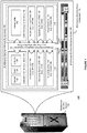
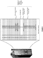
- FIG. 1 shows an illustration of a middleware machine environment 100, in accordance with an embodiment.
- each middleware machine system 102 includes several middleware machine rack components 104, each of which includes a combination of high-performance middleware machine hardware nodes 106 (e.g., 64-bit processors, high performance large memory, and redundant InfiniBand and Ethernet networking), and a middleware machine software environment 108.
- high-performance middleware machine hardware nodes 106 e.g., 64-bit processors, high performance large memory, and redundant InfiniBand and Ethernet networking
- This enables providing a complete application server environment which can be provisioned in minutes, rather than days or months, and which can scale on demand.
- each middleware machine system can be deployed as a full, half, or quarter rack, or other configuration of rack components, and several middleware machine systems can be coupled together, again using InfiniBand, to create larger environments.
- Each middleware machine software environment can be provisioned with several application server or other software instances, for example as shown in Figure 1 , a first application server instance 109 can comprise a virtual machine 116, operating system 120, virtualization layer 124, and application server layer 128 (e.g. WebLogic, including servlet 132, EJB 134, and Gridlink 136 containers); while a second or other application server instance 110 can comprise a virtual machine 116, operating system 120, virtualization layer 124, and data grid layer 140 (e.g.
- each of the application server instances can communicate with one another, and with both its middleware machine hardware node, and other nodes, using a middleware machine integration component 150, herein referred to as an Exalogic integration pack, which itself provides several optimization features, such as support for InfiniBand and other features, each of which are described in further detail below.
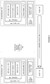
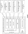
- FIG. 2 shows another illustration of a middleware machine platform or environment, in accordance with an embodiment.
- each application server instance can act either as a sender and/or receiver 160, 161 within the middleware machine environment.
- each application server instance is associated with a muxer 162, 163, that allows the application server instance to communicate with other application server instances via an InfiniBand network 164.
- an application server instance can include a kernel space 162 which in turn can include a sockets direct protocol 168, a user space 164, an application server (e.g. WebLogic) 166, a JVM (e.g.
- the machine integration component can also provide one or more features such as Zero Buffer Copies, Scatter/Gather I/O, T3 Connections, and Lazy Deserialization, to provide the basis for, and improve performance within, the shared infrastructure, each of which are described in further detail below.
- the functional blocks of the present invention may be implemented by hardware, software, or a combination of hardware and software to carry out the principles of the invention. It is understood by persons of skill in the art that the functional blocks described in the figures may be combined or separated into sub-blocks to implement the principles of the invention as described above. Therefore, the description herein may support any possible combination or separation or further definition of the functional blocks described herein.
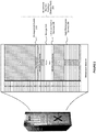
- FIG 3 shows an illustration of a middleware machine provided as a quarter-rack configuration, in accordance with an embodiment.
- the middleware machine can include a plurality of high-performance servers, such as X4170 M2 server nodes; one or more InfiniBand switch/gateways, such as NM2-GW nodes; one or more storage components, such as Maguro RW-2 nodes; and one or more management switches, such as Cisco 4948 switches. Any unused portions of the rack can be left empty or occupied by fillers.
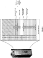
- FIG 4 shows an illustration of a middleware machine provided as a half-rack configuration, in accordance with an embodiment.
- the middleware machine can similarly include a larger number of high-performance servers, such as X4170 M2 server nodes; one or more InfiniBand switch/gateways, such as NM2-GW nodes; one or more storage components, such as Maguro RW-2 nodes; and one or more management switches, such as Cisco 4948 switches. Any unused portions of the rack can be left empty or occupied by fillers. Although they are more plentiful, the hardware components are otherwise the same as those of the quarter-rack configuration.
- FIG. 5 shows an illustration of a middleware machine provided as a full-rack configuration, in accordance with an embodiment.
- the middleware machine can include a larger number of high-performance servers, such as X4170 M2 server nodes; one or more InfiniBand switch/gateways, such as NM2-GW nodes; one or more storage components, such as Maguro RW-2 nodes; and one or more management switches, such as Cisco 4948 switches.
- high-performance servers such as X4170 M2 server nodes
- InfiniBand switch/gateways such as NM2-GW nodes
- storage components such as Maguro RW-2 nodes
- management switches such as Cisco 4948 switches.
- Cisco 4948 switches Cisco 4948 switches
- Figure 6 shows an illustration of a middleware machine platform or environment as it can be used to interface with other systems and networks, in accordance with an embodiment.
- the middleware machine hardware 232 can include a plurality of high-performance servers, such as X4170 M2 server nodes; one or more InfiniBand switch/gateways, such as NM2-GW nodes; one or more storage components, such as Maguro RW-2 nodes; and one or more management switches, such as Cisco 4948 switches, that are coupled together, using InfiniBand, and that can be managed using a management network 234.
- high-performance servers such as X4170 M2 server nodes
- InfiniBand switch/gateways such as NM2-GW nodes
- storage components such as Maguro RW-2 nodes
- management switches such as Cisco 4948 switches
- the InfiniBand switch/gateways can be used to provide 10Gb Ethernet connectivity to one or more data center service networks 236.
- the one or more management switches such as Cisco 4948 switches, can be used to provide 1Gb Ethernet connectivity to one or more data center management networks 236.
- the InfiniBand network can also be used to connect the middleware machines to other middleware machines, or to other machine environments, such as an Exadata machine 240.
- the middleware machine hardware and/or software environment can include additional features, e.g. Zero Buffer Copies, Scatter/Gather I/O, T3 Connections, and Lazy Deserialization, that improve the performance of the middleware machine.
- the system can use zero buffer copying, which avoids buffer copies in components such as WebLogic Server (WLS), JRockit or Hotspot JVM, Oracle Linux or Solaris, and the operating system (OS).
- WLS WebLogic Server
- JRockit or Hotspot JVM Java Virtual Machine
- Oracle Linux or Solaris the operating system
- OS operating system
- embodiments of the present invention provide tight integration between the various layers, enabling them to share memory spaces safely, without increasing risk to system stability. As such this reduces CPU utilization in the User & Kernel space, and as such reduces latency.
- Figure 7 shows a system 300 for providing zero buffer copying, in accordance with an embodiment.
- a number of different features can be provided in each of the Application Server 302, User Space 304, and Kernel Space 306.
- byte buffers can be used instead of static byte arrays and temporary buffers.
- the JSP compiler can use byte buffers 308 instead of static byte arrays.
- a byte buffer can be created by wrapping a backing byte array. Changes made to either the byte buffer or the backing byte array are reflected in the other.
- one byte array can be stored and a byte buffer wrapped around that byte array.
- the changes are applied to the byte array.
- the servlet container can use 310 the byte buffers instead of copying into temporary buffers
- the server core can use 312 byte buffer-aware streams instead of Kernel level chunked streams, and enabling the JVM to pin native memory to WLS buffers instead of copying 314.
- the JVM ensures that that memory is not garbage collected or used by any other process.
- a pointer or reference to the data in memory can be used, instead of copying the data at each step.
- the platform also supports use 318 of Socket Direct Protocol (SDP) that avoids copying of the byte buffer data from the JVM running in user space to the network stack in the kernel space. This further reduces the number of buffer copies while serving HTTP requests. Avoiding copying saves CPU cycles both in the user and the kernel space which reduces latencies for HTTP traffic.
- SDP Socket Direct Protocol
- the application server e.g. WebLogic Server
- a WebLogic Server JSP Compiler can write static JSP content directly into a Java New I/O (NIO) byte buffers.
- NIO Java New I/O
- a web container can pass these byte buffers directly to byte buffer-aware WebLogic Server IO Streams without any copying.
- These byte buffers can be then directly written out by the NIO Muxer using gathered writes.
- a JVM e.g. JRockit or HotSpot JVM
- Exalogic can pin these byte buffers in memory and avoid making a copy of the data to the native memory.
- FIG. 8 shows a flowchart of a method for zero buffer copying, in accordance with an embodiment.
- one or more high performance computing systems each including one or more processors and a high performance memory
- a user space which includes a Java virtual machine (JVM) and one or more application server instances
- JVM Java virtual machine
- a plurality of byte buffers accesible to the JVM and the one or more application server instances are provided.
- a request is received by a first application server instance.
- data associated with the request is stored in a heap space associated with the JVM.
- the JVM pins a portion of the heap space where the data is stored.
- the data is pushed to a first byte buffer where it is accessed by the first application server instance.
- a response is generated by the first application server, using the data.
- the response is sent by the first application server.
- the method shown in Figure 8 can further include the steps of providing a kernel space which includes support for sockets direct protocol (SDP); and providing one or more byte buffer-aware streams accessible to the kernel space and the user space.
- each byte buffer can be a Java New I/O (NIO) byte buffer.
- the request can be an HTTP request.
- the first byte buffer can include a reference pointing to where the data is stored in the heap space.
- the system can use Scatter/Gather I/O, which minimizes fragmentation of network packets, allowing the OS to perform fragmentation based on the use of Java New I/O (NIO).
- the system uses Internet Protocol over InfiniBand (IPoIB) protocol, which has a maximum transfer unit (MTU) of 64KB.
- MTU maximum transfer unit
- IPolB allows the application server, e.g. WebLogic Server, to write more data at a time.
- typical Ethernet connections provide speeds on the order of 1Gb/s, however, by using an InfiniBand network, speeds of upwards of 40 Gb/s are available. This provides greater flexibility and allows much more data to be passed through the connection.
- the system that utilizes such a connection can adapt to push more data through the network to saturate, and efficiently use, the available bandwidth.
- FIG 9 shows a system that utilizes Ethernet protocol, in accordance with an embodiment.
- data can only be written in relatively small portions.
- server 502 is connected to server 504 via an Ethernet network 500.
- the two servers communicate across a single channel using single muxers 506 and 508.
- Data transmissions are limited by the Ethernet connection which, as shown in Figure 9 , force the servers to communicate in 4KB chunks. Attempts to transmit more data than this at a time, and the capacity of the network will be exceeded. This forces more work to be performed at the kernel level, specifically the kernel level divides the data into smaller units and imposes flow control on the fly. This can be costly in time and resources.
- FIG. 10 shows a system that utilizes IPolB and parallel muxing, in accordance with an embodiment.
- the InfiniBand network provides greater bandwidth compared to typical Ethernet connections. This greater bandwidth allows for a larger MTU to be used.
- server 506 is connected to server 508 over an InfiniBand network 510.
- the system can push data through in much larger, as compared to Ethernet, 64KB chunks.
- the kernel level recognizes the increased bandwidth and pushes the larger data units without performing the additional work of further dividing the data into smaller units and imposing flow control.
- multiple parallel logical connections i.e., channels
- each server utilizes a parallel muxer, 512 and 514, which can manage the various connections to ensure that the multiple threads do not interfere with, or block, one another. This further improves the use of the available bandwidth improving the efficiency of data transfers between servers.
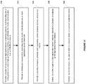
- FIG. 11 shows a flowchart of a method for providing scatter/gather I/O in accordance with an embodiment.
- a cluster of one or more high performance computing systems is provided.
- Each high performance computing system can include one or more processors and a high performance memory.
- the cluster can communicate over an InfiniBand network.
- a middleware environment executing on the cluster, that includes one or more application server instances is provided.
- a plurality of muxers are provided.
- Each application server instance includes at least one muxer.
- a first muxer on a first application server instance, collects data from a plurality of locations in the high performance memory.
- the first muxer transfers the data in bulk to a second muxer on a second application server.
- the method shown in Figure 11 can further include comprising managing, by each muxer, a plurality of threads transmitting data across a plurality of parallel channels.
- a user can configure how many parallel channels are included in the plurality of parallel channels.
- each muxer can be a New I/O (NIO) muxer.
- NIO New I/O
- each data transfer can use scatter/gather data processing.
- One such system can include a cluster of one or more high performance computing systems, each including one or more processors and a high performance memory.
- the cluster communicates over an InfiniBand network.
- the system can also include a middleware environment, executing on the cluster, that includes one or more application server instances.
- the system can further include a plurality of muxers, wherein each application server instance includes at least one muxer.
- Each muxer can receive information from a plurality of threads to transmit to a different muxer on a different application server instance over the Infiniband network using a plurality of parallel channels.
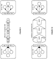
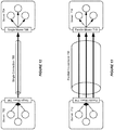
- FIG. 12 shows a system that utilizes a single connection between servers, in accordance with an embodiment.
- a single connection 700 is effected between servers 702 and 704.
- communications from server 702 are sent to a single muxer 706, where they are transmitted to server 704 over the single connection 700.
- a corresponding single muxer 708 at server 704 then forwards the communications to their appropriate destinations.
- this single connection is unable to fully utilize bandwidth available in an InfiniBand (IB) network.
- IB InfiniBand
- FIG. 13 shows a system that utilizes parallel connections between servers, in accordance with an embodiment.
- a plurality of parallel connections 710 can be maintained between servers 712 and 714.
- Each server includes a parallel muxer, 716 and 718, to send communications in parallel over the plurality of connections between the servers.
- the T3, or similar, protocol can be modified to allow multiple connections, which avoids per-connection bottlenecks, and allows better utilization of network bandwidth for features such as in-memory session replication. This enables the available IB bandwidth to be better utilized and provides more efficient communications, with fewer slowdowns, between peers.
- the platform supports the Internet Protocol over InfiniBand (IPoIB) network in its backplane, wherein the network bandwidth of IB is 25Gbps. Since a single connection, such as the T3 in Weblogic Server, is unable to fully utilize IB bandwidth for cluster communication, multiple connections have been created in parallel to better utilize network bandwidth. Multiple connections help in spreading out the session replication network traffic.
- IPoIB Internet Protocol over InfiniBand
- a server for example a WebLogic server using the T3 protocol, can aggregate messages from all threads into a single sender queue which is flushed over the network by a single thread.
- Lock contention can occur when multiple processes require the same lock to proceed, for example lock contention can occur between threads attempting to add messages into the sender queue.
- lock contention is distributed over multiple connections, thus reducing the per connection lock contention.
- implicit replication channels can be created by using the replication channel configured on a ClusterMBean as a template.
- the number of implicit channels created is based on the ServerMBean.getReplicationPorts () attribute.
- the implicit channels copy over all the attributed from the ClusterMBean.ReplicationChannels while overriding the port information to keep it unique.
- the overriding port information is obtained from ServerMBean.getReplicationPorts ().
- the system can include a utility function which can be used to determine if multiple channels are configured. The utility can make the determination once, automatically at regular intervals, in response to changes to the configuration, and/or at the direction of a user and cache the result for subsequent calls.
- the system can further create an exclusive RMI stub for each replication channel configured (stub assigned for each connection).
- the system can hash the sessionID to balance the replication request amongst all the stubs, for example by using round-robin or other similar balancing algorithm.
- the system can also ensure that replication calls are received on one of the replication channels configured for the server.
- using InfiniBand provides more bandwidth than prior systems which, effectively, provides a larger pipe through which data can be transmitted.
- multiple parallel logical connections i.e., channels
- Multiple connections means more concurrent activity can execute without the various executing threads blocking each other. This can be useful, for example for clustering; that is, where multiple servers are communicating with each other in a cluster.
- session data replication between servers is an important feature. Session data can include, for example, shopping cart or other user data that is specific to a particular visit, or session, to a website.
- in-memory session replication to each server can be effected more reliably and more efficiently. This preserves session data in case of server failure and improves the experience of the end user and the service provider.
- FIG 14 shows a flowchart of a method for providing parallel muxing between servers in a cluster, in accordance with an embodiment.
- a cluster of one or more high performance computing systems is provided.
- Each of the high performance computing systems can include one or more processors and a high performance memory. Additionally, the cluster can communicate over an InfiniBand network.
- a middleware environment which executes on the cluster, is provided.
- the middleware environment can include one or more application server instances.
- a plurality of muxers are provided.
- Each application server instance can include at least one muxer.
- a first muxer at a first application server instance, receives information from a plurality of threads to transmit to a second muxer at a second application server instance.
- the information is transmitted to the second muxer over the Infiniband network using a plurality of parallel channels.
- the method shown in Figure 14 can also include configuring how many parallel channels are included in the plurality of parallel channels, based on input from a user. Additionally, the information transmitted can include session data. Furthermore, each muxer can be a New I/O (NIO) muxer. The method shown in Figure 14 can further include creating an RMI stub for each of the plurality of parallel channels.
- NEO New I/O
- the system can support in-memory session replication in a server cluster using a lazy deserialization approach.
- a middleware machine platform or environment can include one or more clusters of application servers. The system is able to recover from service failures, so that the middleware machine platform can provide high availability.
- session state is used in the middleware machine platform for storing important user session information.
- the system can use different methods for replicating session state associated with user service request across clusters, such as in-memory replication and JDBC-based persistence. Using in-memory replication, the system copies a session state from one server instance to another.
- the primary application server creates a primary session state on the server to which the client first connects, and a secondary replica on another server instance in the cluster.
- the replica is kept up-to-date so that it can be used if the primary application server, for example the server that hosts the servlet, fails.
- JDBC-based persistence the system maintains a session state, for example the session state of a servlet or JSP, using file-based or JDBC-based persistence.
- JDBC-based persistence is also used for session state replication within a Wide Area Network (WAN).
- WAN Wide Area Network
- the system can perform a serialization step to convert the primary session data for data transmission.
- the serialization step is a process of converting a complex data structure, such as a parallel arrangement of data, into a serial form.
- the parallel arrangement of data transmits a number of bits at a time along parallel channels, while the serial form transmits one bit at a time.
- Serializing session data introduces some overhead for replicating the session state. The overhead increases as the size of serialized objects grows. For example, if a user plans to create very large objects in a HTTP session, the performance of a servlets may need to be tested to ensure that performance is acceptable.
- session states need to be serializable. Every field in an object needs to be serializable or transient in order for the object to be considered serializable. For example, all servlet and JSP session data in HTTP session states need to be serializable. If the servlet or JSP uses a combination of serializable and non-serializable objects, the system may not replicate the session state of the non-serializable objects.
- session state can be altered using functions provided by the system.
- a special function HttpSession.setAttribute can be used to change attributes in a session object in an HTTP servlet that implements javax.servlet.http.HttpSession. If a user set attributes in a session object with setAttribute, the object and its attributes are replicated in a cluster using in-memory replication. If the user use other set methods to change objects within a session, the system may not replicate those changes. Every time a change is made to an object that is in a session, setAttribute() can be called to update that object across the cluster. Likewise, removeAttribute() can be used to remove an attribute from a session object.
- FIG 15 shows an illustration of a system to support in-memory session replication in a server cluster in accordance with an embodiment.
- a client 901 can interact with a server cluster 900 that includes a primary application server 902 and a secondary application server 903.
- the primary application server operates to receive a request associated with a session 911 from the client at step 921, and maintains session information 912 associated with the session.
- the primary application server can also respond to the client based on the session information.
- the secondary application server operates to receive and maintain serialized session information 913 from the primary application server at step 922.
- the session information maintained on the primary application server can be changed at step 924.
- the primary application server can send these session updates 904 to the secondary application server at step 925.
- the secondary application server operates to update the stored serialized session information based on the session updates received from the primary application server.
- the serialized session data can be stored in a binary format, for example as byte arrays, in the secondary application server.
- the system can apply different logics for updating the binary serialized session data efficiently.
- the system detects the entries in the byte arrays in the secondary application server that are affected by a particular session update. The system can then update the affected entries in the byte arrays directly without the need to replace the whole serialized session data in the byte arrays. This is particularly useful when the stored serialized session data are large in size.
- the secondary application server when the primary application server fails, the secondary application server operates to generate deserialized session information 914 based on the updated serialized session information at step 923.
- the secondary application server or another application server in the middleware environment, can use the deserialized session information and responds to the client at step 926.
- the system can optimize the in-memory session replication process by performing the deserialization step only when the primary application server fails.
- the optimization prevents the deserialization operation when primary application server is alive.
- the system can avoid taking a serialization step in the primary application server and a deserialization step in the secondary application server for every session update, which is expensive in terms of CPU utilization cost and latency overhead, especially when there are frequently session updates.
- a user can further control where secondary states are placed using replication groups.
- a replication group is a preferred list of clustered servers to be used for storing session state replicas.
- a user can assign the server to a replication group, and a preferred secondary replication group for hosting the serialized replica of the primary HTTP session states created on the server.
- the server hosting the primary state ranks other servers in the cluster to determine which server should host the secondary. Server ranks are assigned using a combination of the server's location (whether or not it resides on the same machine as the primary application server) and its participation in the primary application server's preferred replication group.
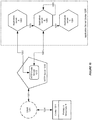
- Figure 16 illustrates an exemplary flow chart for supporting in-memory session replication in a server cluster in accordance with an embodiment.
- a primary application server receives a request associated with a session from a client at step 1001.
- the primary application server also maintains session information associated with the session and responds to the client based on the session information.
- a secondary application server can receive and maintain serialized session information from the primary application server at step 1002.
- the secondary application server can further update the serialized session information based on one or more session updates received from the primary application server at step 1003.
- step 1004 only when the primary application server fails, the updated serialized session information can be deserialized and an application server can respond to the client based on the deserialized session information.
- the system can support two mechanisms for preserving HTTP session state: hardware load balancers and proxy plug-ins.
- a load balancing hardware can simply redirect client requests to any available server in the application server cluster, when a primary application server fails.
- the cluster can obtain the replica of the client's HTTP session state from a secondary application server in the cluster.
- FIG 17 shows an illustration of a system to support in-memory session replication in a server cluster using a load balancer in accordance with an embodiment.
- a load balancer 1110 routes the client's connection request to an application server cluster 1100 in accordance with its configured policies.
- the system directs the request to an application server A 1102, which acts as the primary host of the client's servlet session state at step 1122.
- the system can use a ranking system to select a secondary application server B 1103 to host the serialized session state associates with the session at step 1123.
- the client can record the location of both application server instances A and B in a local cookie 1111 at step 1124. If the client does not allow cookies, the record of the primary and secondary application servers can be recorded in the URL returned to the client via URL rewriting.
- the load balancer uses an identifier in the client-side cookie to ensure that those requests continue to go to the application server A, rather than being load-balanced to another server in the cluster. This ensures that the client remains associated with the server hosting the primary session object for the life of the session.
- the load balancing hardware uses its configured policies to direct the request to an available server in the cluster at step 1125.
- the load balancer routes the client's request to an application server C 1104 after server A fails.
- the server uses the information in the client's cookie, or the information in the HTTP request if URL rewriting is used, to connect to server B.
- the application server C can further acquire the session state through deserializing the serialized session state on server B at step 1126.
- the failover process remains completely transparent to the client. The deserialization step only needs to be performed once after a connection failure.
- Server C becomes the new host for the client's primary session state, and server B continues to host the serialized session state and receive session updates from server C at step 1127.
- This new information about the primary and secondary host is again updated in the client's cookie, or via URL rewriting.
- an application server proxy plug-in maintains a list of application server instances that host a clustered servlet or JSP, and forwards HTTP requests to those instances using a round-robin strategy.
- the plug-in also provides the logic necessary to locate the serialized replica of a client's HTTP session state if an application server instance fails.
- FIG. 18 shows an illustration of a system to support in-memory session replication in a server cluster using a proxy plug-in in accordance with an embodiment.
- a HTTP client 1201 requests a servlet at step 1221
- a HttpClusterServlet 1212 on a HTTP server 1210 proxies the request to the application server cluster 1200.
- the HttpClusterServlet maintains the list of all servers in the cluster, and the load balancing logic to use when accessing the cluster.
- the HttpClusterServlet can route the client request to the servlet hosted on an application server A 1202, which becomes the primary application server hosting the client's servlet session at step 1222.
- the primary application server transmits the serialized client's servlet session state to a secondary application server in the cluster at step 1222.
- application server B 1203 is selected as the secondary application server.
- the servlet page can be returned to the client through the HttpClusterServlet, and the client browser is instructed to write a cookie 1211 that lists the primary and secondary locations of the servlet session state at step 1224. If the client browser does not support cookies, the application server can use URL rewriting instead.
- HttpClusterServlet can use the client's cookie information to determine the location of the secondary application server that hosts the replica of the session state. HttpClusterServlet can automatically redirect the client's next HTTP request to the secondary application server at step 1225. The failover is transparent to the client, and server B can deserialize the serialized session state and acquires acquire the session state at step 1226.
- server B becomes the primary application server hosting the servlet session state, and a new secondary can be created on, for example, an application server C 604.
- Server C can then host the serialized session state and receive session updates from server B at step 1227.
- the proxy updates the client's cookie to reflect the new primary and secondary application servers, to account for the possibility of subsequent failovers.
- an application server in addition to providing HTTP session state replication across servers within a cluster, provides the ability to replicate HTTP session state across multiple clusters. This improves high-availability and fault tolerance by allowing clusters to be spread across multiple geographic regions, power grids, and internet service providers.
- FIG 19 shows an illustration of a system to support in-memory session replication cross server clusters in accordance with an embodiment.
- a global load balancer 1302 is responsible for balancing HTTP requests across clusters 1305 and 1306.
- the global load balancer determines which cluster to send it to basing on the current number of requests being handled by each cluster. Then the request is passed to a local load balancer 1303 or 1304 for the chosen cluster at step 1312 or 1313.
- the local load balancer receives HTTP requests from the global load balancer, the local load balancer is responsible for balancing HTTP requests across servers within the cluster at step 1314 or 1315.
- a replication channel 1310 can be configured to communicate session state information from the primary to the secondary cluster.
- a replication channel can be a network channel that is dedicated specifically to replication traffic between clusters.
- the present invention may be conveniently implemented using one or more conventional general purpose or specialized digital computer, computing device, machine, or microprocessor, including one or more processors, memory and/or computer readable storage media programmed according to the teachings of the present disclosure.
- Appropriate software coding can readily be prepared by skilled programmers based on the teachings of the present disclosure, as will be apparent to those skilled in the software art.
- the present invention includes a computer program product which is a storage medium or computer readable medium (media) having instructions stored thereon/in which can be used to program a computer to perform any of the processes of the present invention.
- the storage medium can include, but is not limited to, any type of disk including floppy disks, optical discs, DVD, CD-ROMs, microdrive, and magneto-optical disks, ROMs, RAMs, EPROMs, EEPROMs, DRAMs, VRAMs, flash memory devices, magnetic or optical cards, nanosystems (including molecular memory ICs), or any type of media or device suitable for storing instructions and/or data.
Landscapes
- Engineering & Computer Science (AREA)
- Computer Networks & Wireless Communication (AREA)
- Signal Processing (AREA)
- Theoretical Computer Science (AREA)
- Databases & Information Systems (AREA)
- Physics & Mathematics (AREA)
- General Physics & Mathematics (AREA)
- General Engineering & Computer Science (AREA)
- Data Mining & Analysis (AREA)
- Computing Systems (AREA)
- Computer Security & Cryptography (AREA)
- Computer Hardware Design (AREA)
- Mathematical Physics (AREA)
- Software Systems (AREA)
- Computer And Data Communications (AREA)
- Multi Processors (AREA)
Applications Claiming Priority (7)
| Application Number | Priority Date | Filing Date | Title |
|---|---|---|---|
| US38328510P | 2010-09-15 | 2010-09-15 | |
| US38422710P | 2010-09-17 | 2010-09-17 | |
| US13/109,849 US8856460B2 (en) | 2010-09-15 | 2011-05-17 | System and method for zero buffer copying in a middleware environment |
| US13/109,871 US8756329B2 (en) | 2010-09-15 | 2011-05-17 | System and method for parallel multiplexing between servers in a cluster |
| US13/167,636 US9811541B2 (en) | 2010-09-15 | 2011-06-23 | System and method for supporting lazy deserialization of session information in a server cluster |
| US13/170,490 US9864759B2 (en) | 2010-09-15 | 2011-06-28 | System and method for providing scatter/gather data processing in a middleware environment |
| PCT/US2011/051697 WO2012037310A1 (en) | 2010-09-15 | 2011-09-15 | System including a middleware machine environment |
Publications (2)
| Publication Number | Publication Date |
|---|---|
| EP2616967A1 EP2616967A1 (en) | 2013-07-24 |
| EP2616967B1 true EP2616967B1 (en) | 2019-10-23 |
Family
ID=56291249
Family Applications (1)
| Application Number | Title | Priority Date | Filing Date |
|---|---|---|---|
| EP11764902.0A Active EP2616967B1 (en) | 2010-09-15 | 2011-09-15 | System including a middleware machine environment |
Country Status (4)
| Country | Link |
|---|---|
| EP (1) | EP2616967B1 (enExample) |
| JP (1) | JP5945543B2 (enExample) |
| CN (1) | CN103140851B (enExample) |
| WO (1) | WO2012037310A1 (enExample) |
Families Citing this family (8)
| Publication number | Priority date | Publication date | Assignee | Title |
|---|---|---|---|---|
| CN103457844B (zh) * | 2013-08-12 | 2016-12-28 | 中国石油天然气股份有限公司 | 多Infiniband网关的vNIC绑定方法 |
| CN104780184A (zh) * | 2014-01-09 | 2015-07-15 | 华耀(中国)科技有限公司 | 一种利用地理位置信息进行负载均衡的方法 |
| US10291548B2 (en) * | 2014-08-08 | 2019-05-14 | Oracle International Corporation | Contribution policy-based resource management and allocation system |
| CN107872539B (zh) * | 2017-12-15 | 2021-01-15 | 安徽长泰信息安全服务有限公司 | 一种基于云计算平台的数据处理系统及方法 |
| US20200133267A1 (en) * | 2018-10-25 | 2020-04-30 | GM Global Technology Operations LLC | Middleware support for fault-tolerant execution in an adaptive platform for a vehicle |
| JP7436923B2 (ja) * | 2020-01-23 | 2024-02-22 | ヒタチ ヴァンタラ エルエルシー | アドオンカードのファームウェアを更新し、任意のosがインストールされた任意のサーバ又はベアメタルサーバのハードウェア情報を収集するシステム及び方法 |
| US11321259B2 (en) * | 2020-02-14 | 2022-05-03 | Sony Interactive Entertainment Inc. | Network architecture providing high speed storage access through a PCI express fabric between a compute node and a storage server |
| CN114840448B (zh) * | 2022-05-13 | 2024-06-04 | 厦门大学 | 利用通道间并行加速3d闪存垃圾回收的方法 |
Family Cites Families (8)
| Publication number | Priority date | Publication date | Assignee | Title |
|---|---|---|---|---|
| US7209921B2 (en) * | 2000-09-01 | 2007-04-24 | Op40, Inc. | Method and system for deploying an asset over a multi-tiered network |
| US7143227B2 (en) * | 2003-02-18 | 2006-11-28 | Dot Hill Systems Corporation | Broadcast bridge apparatus for transferring data to redundant memory subsystems in a storage controller |
| JP2003196229A (ja) * | 2001-12-28 | 2003-07-11 | Sony Corp | バス・インタフェースにおけるデータ転送方法およびバス・インタフェース |
| US7930422B2 (en) * | 2004-07-14 | 2011-04-19 | International Business Machines Corporation | Apparatus and method for supporting memory management in an offload of network protocol processing |
| US8166460B2 (en) * | 2006-10-10 | 2012-04-24 | Convergys Cmg Utah, Inc. | System and method for analyzing HTTP sessions |
| CN100586058C (zh) * | 2007-11-20 | 2010-01-27 | 中国人民解放军信息工程大学 | 基于j2ee中间件规范的容忍入侵应用服务器及容忍入侵方法 |
| JP5352848B2 (ja) * | 2008-11-28 | 2013-11-27 | 株式会社日立製作所 | 仮想計算機の制御方法及び計算機装置 |
| US8612930B2 (en) * | 2009-01-30 | 2013-12-17 | Oracle America, Inc. | Methods and apparatus for dynamic class reloading and versioning |
-
2011
- 2011-09-15 JP JP2013529312A patent/JP5945543B2/ja active Active
- 2011-09-15 EP EP11764902.0A patent/EP2616967B1/en active Active
- 2011-09-15 WO PCT/US2011/051697 patent/WO2012037310A1/en not_active Ceased
- 2011-09-15 CN CN201180039804.7A patent/CN103140851B/zh active Active
Non-Patent Citations (1)
| Title |
|---|
| None * |
Also Published As
| Publication number | Publication date |
|---|---|
| JP2013543169A (ja) | 2013-11-28 |
| EP2616967A1 (en) | 2013-07-24 |
| JP5945543B2 (ja) | 2016-07-05 |
| CN103140851A (zh) | 2013-06-05 |
| WO2012037310A1 (en) | 2012-03-22 |
| CN103140851B (zh) | 2016-11-23 |
Similar Documents
| Publication | Publication Date | Title |
|---|---|---|
| US9185054B2 (en) | System and method for providing zero buffer copying in a middleware machine environment | |
| US9811541B2 (en) | System and method for supporting lazy deserialization of session information in a server cluster | |
| EP2616967B1 (en) | System including a middleware machine environment | |
| EP2893689B1 (en) | System and method for supporting a scalable message bus in a distributed data grid cluster | |
| US8375001B2 (en) | Master monitoring mechanism for a geographical distributed database | |
| US9614746B2 (en) | System and method for providing ethernet over network virtual hub scalability in a middleware machine environment | |
| US20140149485A1 (en) | Method and system for managing user state for applications deployed on platform as a service (paas) clouds | |
| US20150312376A1 (en) | System and method for supporting a bypass-domain model for across-domain messaging in a transactional middleware machine environment | |
| US10826977B2 (en) | System and method for supporting asynchronous request/response in a network environment | |
| US11936723B2 (en) | Systems and methods for geographically distributed node replication | |
| CN113709220A (zh) | 虚拟负载均衡器的高可用实现方法、系统及电子设备 | |
| CN114885007B (zh) | 用于实时的强一致性会话同步的方法和电子设备 | |
| Al-Kiswany et al. | Nice: Network-integrated cluster-efficient storage | |
| Kettaneh et al. | The network-integrated storage system | |
| US9118581B2 (en) | Routing network traffic | |
| CN115328651A (zh) | 基于国产vpx服务器的轻量化微云系统 | |
| CN113992683B (zh) | 实现同一集群中双网络有效隔离的方法、系统、设备及介质 | |
| CN114945023B (zh) | 一种网络连接复用方法、装置、设备及介质 | |
| CN116743845B (zh) | 边缘服务发现方法、装置、节点设备和可读存储介质 | |
| Server | Server |
Legal Events
| Date | Code | Title | Description |
|---|---|---|---|
| PUAI | Public reference made under article 153(3) epc to a published international application that has entered the european phase |
Free format text: ORIGINAL CODE: 0009012 |
|
| 17P | Request for examination filed |
Effective date: 20130226 |
|
| AK | Designated contracting states |
Kind code of ref document: A1 Designated state(s): AL AT BE BG CH CY CZ DE DK EE ES FI FR GB GR HR HU IE IS IT LI LT LU LV MC MK MT NL NO PL PT RO RS SE SI SK SM TR |
|
| DAX | Request for extension of the european patent (deleted) | ||
| STAA | Information on the status of an ep patent application or granted ep patent |
Free format text: STATUS: EXAMINATION IS IN PROGRESS |
|
| 17Q | First examination report despatched |
Effective date: 20180910 |
|
| REG | Reference to a national code |
Ref country code: DE Ref legal event code: R079 Ref document number: 602011062913 Country of ref document: DE Free format text: PREVIOUS MAIN CLASS: G06F0017300000 Ipc: G06F0016230000 |
|
| GRAP | Despatch of communication of intention to grant a patent |
Free format text: ORIGINAL CODE: EPIDOSNIGR1 |
|
| STAA | Information on the status of an ep patent application or granted ep patent |
Free format text: STATUS: GRANT OF PATENT IS INTENDED |
|
| INTG | Intention to grant announced |
Effective date: 20190430 |
|
| RIC1 | Information provided on ipc code assigned before grant |
Ipc: G06F 16/27 20190101ALI20190415BHEP Ipc: G06F 16/20 20190101ALI20190415BHEP Ipc: G06F 16/23 20190101AFI20190415BHEP |
|
| GRAS | Grant fee paid |
Free format text: ORIGINAL CODE: EPIDOSNIGR3 |
|
| GRAA | (expected) grant |
Free format text: ORIGINAL CODE: 0009210 |
|
| STAA | Information on the status of an ep patent application or granted ep patent |
Free format text: STATUS: THE PATENT HAS BEEN GRANTED |
|
| AK | Designated contracting states |
Kind code of ref document: B1 Designated state(s): AL AT BE BG CH CY CZ DE DK EE ES FI FR GB GR HR HU IE IS IT LI LT LU LV MC MK MT NL NO PL PT RO RS SE SI SK SM TR |
|
| REG | Reference to a national code |
Ref country code: GB Ref legal event code: FG4D |
|
| REG | Reference to a national code |
Ref country code: CH Ref legal event code: EP |
|
| REG | Reference to a national code |
Ref country code: IE Ref legal event code: FG4D |
|
| REG | Reference to a national code |
Ref country code: DE Ref legal event code: R096 Ref document number: 602011062913 Country of ref document: DE |
|
| REG | Reference to a national code |
Ref country code: AT Ref legal event code: REF Ref document number: 1194458 Country of ref document: AT Kind code of ref document: T Effective date: 20191115 |
|
| REG | Reference to a national code |
Ref country code: NL Ref legal event code: MP Effective date: 20191023 |
|
| REG | Reference to a national code |
Ref country code: LT Ref legal event code: MG4D |
|
| PG25 | Lapsed in a contracting state [announced via postgrant information from national office to epo] |
Ref country code: PT Free format text: LAPSE BECAUSE OF FAILURE TO SUBMIT A TRANSLATION OF THE DESCRIPTION OR TO PAY THE FEE WITHIN THE PRESCRIBED TIME-LIMIT Effective date: 20200224 Ref country code: BG Free format text: LAPSE BECAUSE OF FAILURE TO SUBMIT A TRANSLATION OF THE DESCRIPTION OR TO PAY THE FEE WITHIN THE PRESCRIBED TIME-LIMIT Effective date: 20200123 Ref country code: FI Free format text: LAPSE BECAUSE OF FAILURE TO SUBMIT A TRANSLATION OF THE DESCRIPTION OR TO PAY THE FEE WITHIN THE PRESCRIBED TIME-LIMIT Effective date: 20191023 Ref country code: LV Free format text: LAPSE BECAUSE OF FAILURE TO SUBMIT A TRANSLATION OF THE DESCRIPTION OR TO PAY THE FEE WITHIN THE PRESCRIBED TIME-LIMIT Effective date: 20191023 Ref country code: SE Free format text: LAPSE BECAUSE OF FAILURE TO SUBMIT A TRANSLATION OF THE DESCRIPTION OR TO PAY THE FEE WITHIN THE PRESCRIBED TIME-LIMIT Effective date: 20191023 Ref country code: NL Free format text: LAPSE BECAUSE OF FAILURE TO SUBMIT A TRANSLATION OF THE DESCRIPTION OR TO PAY THE FEE WITHIN THE PRESCRIBED TIME-LIMIT Effective date: 20191023 Ref country code: LT Free format text: LAPSE BECAUSE OF FAILURE TO SUBMIT A TRANSLATION OF THE DESCRIPTION OR TO PAY THE FEE WITHIN THE PRESCRIBED TIME-LIMIT Effective date: 20191023 Ref country code: PL Free format text: LAPSE BECAUSE OF FAILURE TO SUBMIT A TRANSLATION OF THE DESCRIPTION OR TO PAY THE FEE WITHIN THE PRESCRIBED TIME-LIMIT Effective date: 20191023 Ref country code: NO Free format text: LAPSE BECAUSE OF FAILURE TO SUBMIT A TRANSLATION OF THE DESCRIPTION OR TO PAY THE FEE WITHIN THE PRESCRIBED TIME-LIMIT Effective date: 20200123 Ref country code: GR Free format text: LAPSE BECAUSE OF FAILURE TO SUBMIT A TRANSLATION OF THE DESCRIPTION OR TO PAY THE FEE WITHIN THE PRESCRIBED TIME-LIMIT Effective date: 20200124 Ref country code: ES Free format text: LAPSE BECAUSE OF FAILURE TO SUBMIT A TRANSLATION OF THE DESCRIPTION OR TO PAY THE FEE WITHIN THE PRESCRIBED TIME-LIMIT Effective date: 20191023 |
|
| PG25 | Lapsed in a contracting state [announced via postgrant information from national office to epo] |
Ref country code: RS Free format text: LAPSE BECAUSE OF FAILURE TO SUBMIT A TRANSLATION OF THE DESCRIPTION OR TO PAY THE FEE WITHIN THE PRESCRIBED TIME-LIMIT Effective date: 20191023 Ref country code: HR Free format text: LAPSE BECAUSE OF FAILURE TO SUBMIT A TRANSLATION OF THE DESCRIPTION OR TO PAY THE FEE WITHIN THE PRESCRIBED TIME-LIMIT Effective date: 20191023 Ref country code: IS Free format text: LAPSE BECAUSE OF FAILURE TO SUBMIT A TRANSLATION OF THE DESCRIPTION OR TO PAY THE FEE WITHIN THE PRESCRIBED TIME-LIMIT Effective date: 20200224 |
|
| PG25 | Lapsed in a contracting state [announced via postgrant information from national office to epo] |
Ref country code: AL Free format text: LAPSE BECAUSE OF FAILURE TO SUBMIT A TRANSLATION OF THE DESCRIPTION OR TO PAY THE FEE WITHIN THE PRESCRIBED TIME-LIMIT Effective date: 20191023 |
|
| REG | Reference to a national code |
Ref country code: DE Ref legal event code: R097 Ref document number: 602011062913 Country of ref document: DE |
|
| PG2D | Information on lapse in contracting state deleted |
Ref country code: IS |
|
| PG25 | Lapsed in a contracting state [announced via postgrant information from national office to epo] |
Ref country code: DK Free format text: LAPSE BECAUSE OF FAILURE TO SUBMIT A TRANSLATION OF THE DESCRIPTION OR TO PAY THE FEE WITHIN THE PRESCRIBED TIME-LIMIT Effective date: 20191023 Ref country code: EE Free format text: LAPSE BECAUSE OF FAILURE TO SUBMIT A TRANSLATION OF THE DESCRIPTION OR TO PAY THE FEE WITHIN THE PRESCRIBED TIME-LIMIT Effective date: 20191023 Ref country code: CZ Free format text: LAPSE BECAUSE OF FAILURE TO SUBMIT A TRANSLATION OF THE DESCRIPTION OR TO PAY THE FEE WITHIN THE PRESCRIBED TIME-LIMIT Effective date: 20191023 Ref country code: RO Free format text: LAPSE BECAUSE OF FAILURE TO SUBMIT A TRANSLATION OF THE DESCRIPTION OR TO PAY THE FEE WITHIN THE PRESCRIBED TIME-LIMIT Effective date: 20191023 Ref country code: IS Free format text: LAPSE BECAUSE OF FAILURE TO SUBMIT A TRANSLATION OF THE DESCRIPTION OR TO PAY THE FEE WITHIN THE PRESCRIBED TIME-LIMIT Effective date: 20200223 |
|
| REG | Reference to a national code |
Ref country code: AT Ref legal event code: MK05 Ref document number: 1194458 Country of ref document: AT Kind code of ref document: T Effective date: 20191023 |
|
| PLBE | No opposition filed within time limit |
Free format text: ORIGINAL CODE: 0009261 |
|
| STAA | Information on the status of an ep patent application or granted ep patent |
Free format text: STATUS: NO OPPOSITION FILED WITHIN TIME LIMIT |
|
| PG25 | Lapsed in a contracting state [announced via postgrant information from national office to epo] |
Ref country code: SK Free format text: LAPSE BECAUSE OF FAILURE TO SUBMIT A TRANSLATION OF THE DESCRIPTION OR TO PAY THE FEE WITHIN THE PRESCRIBED TIME-LIMIT Effective date: 20191023 Ref country code: IT Free format text: LAPSE BECAUSE OF FAILURE TO SUBMIT A TRANSLATION OF THE DESCRIPTION OR TO PAY THE FEE WITHIN THE PRESCRIBED TIME-LIMIT Effective date: 20191023 Ref country code: SM Free format text: LAPSE BECAUSE OF FAILURE TO SUBMIT A TRANSLATION OF THE DESCRIPTION OR TO PAY THE FEE WITHIN THE PRESCRIBED TIME-LIMIT Effective date: 20191023 |
|
| 26N | No opposition filed |
Effective date: 20200724 |
|
| PG25 | Lapsed in a contracting state [announced via postgrant information from national office to epo] |
Ref country code: AT Free format text: LAPSE BECAUSE OF FAILURE TO SUBMIT A TRANSLATION OF THE DESCRIPTION OR TO PAY THE FEE WITHIN THE PRESCRIBED TIME-LIMIT Effective date: 20191023 Ref country code: SI Free format text: LAPSE BECAUSE OF FAILURE TO SUBMIT A TRANSLATION OF THE DESCRIPTION OR TO PAY THE FEE WITHIN THE PRESCRIBED TIME-LIMIT Effective date: 20191023 |
|
| PG25 | Lapsed in a contracting state [announced via postgrant information from national office to epo] |
Ref country code: MC Free format text: LAPSE BECAUSE OF FAILURE TO SUBMIT A TRANSLATION OF THE DESCRIPTION OR TO PAY THE FEE WITHIN THE PRESCRIBED TIME-LIMIT Effective date: 20191023 |
|
| REG | Reference to a national code |
Ref country code: CH Ref legal event code: PL |
|
| REG | Reference to a national code |
Ref country code: BE Ref legal event code: MM Effective date: 20200930 |
|
| PG25 | Lapsed in a contracting state [announced via postgrant information from national office to epo] |
Ref country code: LU Free format text: LAPSE BECAUSE OF NON-PAYMENT OF DUE FEES Effective date: 20200915 |
|
| PG25 | Lapsed in a contracting state [announced via postgrant information from national office to epo] |
Ref country code: FR Free format text: LAPSE BECAUSE OF NON-PAYMENT OF DUE FEES Effective date: 20200930 |
|
| PG25 | Lapsed in a contracting state [announced via postgrant information from national office to epo] |
Ref country code: CH Free format text: LAPSE BECAUSE OF NON-PAYMENT OF DUE FEES Effective date: 20200930 Ref country code: BE Free format text: LAPSE BECAUSE OF NON-PAYMENT OF DUE FEES Effective date: 20200930 Ref country code: IE Free format text: LAPSE BECAUSE OF NON-PAYMENT OF DUE FEES Effective date: 20200915 Ref country code: LI Free format text: LAPSE BECAUSE OF NON-PAYMENT OF DUE FEES Effective date: 20200930 |
|
| PG25 | Lapsed in a contracting state [announced via postgrant information from national office to epo] |
Ref country code: TR Free format text: LAPSE BECAUSE OF FAILURE TO SUBMIT A TRANSLATION OF THE DESCRIPTION OR TO PAY THE FEE WITHIN THE PRESCRIBED TIME-LIMIT Effective date: 20191023 Ref country code: MT Free format text: LAPSE BECAUSE OF FAILURE TO SUBMIT A TRANSLATION OF THE DESCRIPTION OR TO PAY THE FEE WITHIN THE PRESCRIBED TIME-LIMIT Effective date: 20191023 Ref country code: CY Free format text: LAPSE BECAUSE OF FAILURE TO SUBMIT A TRANSLATION OF THE DESCRIPTION OR TO PAY THE FEE WITHIN THE PRESCRIBED TIME-LIMIT Effective date: 20191023 |
|
| PG25 | Lapsed in a contracting state [announced via postgrant information from national office to epo] |
Ref country code: MK Free format text: LAPSE BECAUSE OF FAILURE TO SUBMIT A TRANSLATION OF THE DESCRIPTION OR TO PAY THE FEE WITHIN THE PRESCRIBED TIME-LIMIT Effective date: 20191023 |
|
| P01 | Opt-out of the competence of the unified patent court (upc) registered |
Effective date: 20230522 |
|
| PGFP | Annual fee paid to national office [announced via postgrant information from national office to epo] |
Ref country code: DE Payment date: 20250730 Year of fee payment: 15 |
|
| PGFP | Annual fee paid to national office [announced via postgrant information from national office to epo] |
Ref country code: GB Payment date: 20250731 Year of fee payment: 15 |