EP2616789B1 - Pressure sensor configuration for pressurized tank - Google Patents
Pressure sensor configuration for pressurized tank Download PDFInfo
- Publication number
- EP2616789B1 EP2616789B1 EP11825625.4A EP11825625A EP2616789B1 EP 2616789 B1 EP2616789 B1 EP 2616789B1 EP 11825625 A EP11825625 A EP 11825625A EP 2616789 B1 EP2616789 B1 EP 2616789B1
- Authority
- EP
- European Patent Office
- Prior art keywords
- pressure sensor
- pressure
- rtu
- sensor configuration
- tank
- Prior art date
- Legal status (The legal status is an assumption and is not a legal conclusion. Google has not performed a legal analysis and makes no representation as to the accuracy of the status listed.)
- Active
Links
- 238000005259 measurement Methods 0.000 claims description 25
- 238000009530 blood pressure measurement Methods 0.000 claims description 22
- 238000004891 communication Methods 0.000 claims description 19
- 239000007788 liquid Substances 0.000 claims description 16
- 238000000034 method Methods 0.000 claims description 16
- 238000004364 calculation method Methods 0.000 claims description 8
- 230000008569 process Effects 0.000 description 6
- 238000009429 electrical wiring Methods 0.000 description 5
- 238000012545 processing Methods 0.000 description 4
- 238000007726 management method Methods 0.000 description 3
- 238000012544 monitoring process Methods 0.000 description 3
- 230000003068 static effect Effects 0.000 description 3
- XAGFODPZIPBFFR-UHFFFAOYSA-N aluminium Chemical compound [Al] XAGFODPZIPBFFR-UHFFFAOYSA-N 0.000 description 2
- 229910052782 aluminium Inorganic materials 0.000 description 2
- 230000008859 change Effects 0.000 description 2
- 238000013500 data storage Methods 0.000 description 2
- 238000012986 modification Methods 0.000 description 2
- 230000004048 modification Effects 0.000 description 2
- 230000000704 physical effect Effects 0.000 description 2
- 230000004044 response Effects 0.000 description 2
- 238000012384 transportation and delivery Methods 0.000 description 2
- 229910001369 Brass Inorganic materials 0.000 description 1
- RYGMFSIKBFXOCR-UHFFFAOYSA-N Copper Chemical compound [Cu] RYGMFSIKBFXOCR-UHFFFAOYSA-N 0.000 description 1
- 239000010951 brass Substances 0.000 description 1
- 230000010267 cellular communication Effects 0.000 description 1
- 230000001413 cellular effect Effects 0.000 description 1
- 239000010949 copper Substances 0.000 description 1
- 229910052802 copper Inorganic materials 0.000 description 1
- 238000013523 data management Methods 0.000 description 1
- 230000009977 dual effect Effects 0.000 description 1
- 230000000694 effects Effects 0.000 description 1
- 239000000463 material Substances 0.000 description 1
- 230000007246 mechanism Effects 0.000 description 1
- 239000000126 substance Substances 0.000 description 1
- 230000002277 temperature effect Effects 0.000 description 1
Images




Classifications
-
- G—PHYSICS
- G01—MEASURING; TESTING
- G01L—MEASURING FORCE, STRESS, TORQUE, WORK, MECHANICAL POWER, MECHANICAL EFFICIENCY, OR FLUID PRESSURE
- G01L19/00—Details of, or accessories for, apparatus for measuring steady or quasi-steady pressure of a fluent medium insofar as such details or accessories are not special to particular types of pressure gauges
- G01L19/0007—Fluidic connecting means
- G01L19/0015—Fluidic connecting means using switching means
-
- G—PHYSICS
- G01—MEASURING; TESTING
- G01F—MEASURING VOLUME, VOLUME FLOW, MASS FLOW OR LIQUID LEVEL; METERING BY VOLUME
- G01F23/00—Indicating or measuring liquid level or level of fluent solid material, e.g. indicating in terms of volume or indicating by means of an alarm
- G01F23/80—Arrangements for signal processing
- G01F23/802—Particular electronic circuits for digital processing equipment
-
- G—PHYSICS
- G01—MEASURING; TESTING
- G01F—MEASURING VOLUME, VOLUME FLOW, MASS FLOW OR LIQUID LEVEL; METERING BY VOLUME
- G01F22/00—Methods or apparatus for measuring volume of fluids or fluent solid material, not otherwise provided for
- G01F22/02—Methods or apparatus for measuring volume of fluids or fluent solid material, not otherwise provided for involving measurement of pressure
-
- G—PHYSICS
- G01—MEASURING; TESTING
- G01F—MEASURING VOLUME, VOLUME FLOW, MASS FLOW OR LIQUID LEVEL; METERING BY VOLUME
- G01F23/00—Indicating or measuring liquid level or level of fluent solid material, e.g. indicating in terms of volume or indicating by means of an alarm
- G01F23/14—Indicating or measuring liquid level or level of fluent solid material, e.g. indicating in terms of volume or indicating by means of an alarm by measurement of pressure
-
- G—PHYSICS
- G01—MEASURING; TESTING
- G01F—MEASURING VOLUME, VOLUME FLOW, MASS FLOW OR LIQUID LEVEL; METERING BY VOLUME
- G01F23/00—Indicating or measuring liquid level or level of fluent solid material, e.g. indicating in terms of volume or indicating by means of an alarm
- G01F23/14—Indicating or measuring liquid level or level of fluent solid material, e.g. indicating in terms of volume or indicating by means of an alarm by measurement of pressure
- G01F23/16—Indicating, recording, or alarm devices being actuated by mechanical or fluid means, e.g. using gas, mercury, or a diaphragm as transmitting element, or by a column of liquid
- G01F23/164—Indicating, recording, or alarm devices being actuated by mechanical or fluid means, e.g. using gas, mercury, or a diaphragm as transmitting element, or by a column of liquid using a diaphragm, bellow as transmitting element
-
- G—PHYSICS
- G01—MEASURING; TESTING
- G01F—MEASURING VOLUME, VOLUME FLOW, MASS FLOW OR LIQUID LEVEL; METERING BY VOLUME
- G01F23/00—Indicating or measuring liquid level or level of fluent solid material, e.g. indicating in terms of volume or indicating by means of an alarm
- G01F23/14—Indicating or measuring liquid level or level of fluent solid material, e.g. indicating in terms of volume or indicating by means of an alarm by measurement of pressure
- G01F23/18—Indicating, recording or alarm devices actuated electrically
Definitions
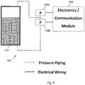
- Pressure sensors have various applications. As an example, pressure sensors have been used to determine parameters (e.g. , level, volume, mass) of liquid in a pressurized liquid storage tank. Figs. 1-4 show various existing pressure sensor configurations for this application.
- Fig. 1 shows a pressure sensor configuration 100 comprising a pressurized tank 102 coupled to a pressure sensor 104 and a differential pressure sensor 106 via pressure piping.
- the pressure sensor 104 measures pressure at the top (HI) port of the tank 102 (compared to vacuum or atmospheric pressure) and the differential pressure sensor 106 measures a difference in pressure between the HI port and LO port of the tank 102.
- the pressure measurements from the pressure sensor 104 and the differential pressure sensor 106 are provided to an electronics/communication module 108 via electrical wiring.
- the electronics/communication module 108 processes the pressure measurements from the pressure sensor 104 and the differential pressure sensor 106 and/or forwards these pressure measurements to a remote computer for processing.
- a pressure sensor configuration 200 is shown with a combo pressure/differential pressure (PDP) sensor 204 coupled to the tank 102 via pressure piping.
- the combo PDP sensor 204 comprises a pressure sensor and a differential pressure sensor integrated into a single unit to reduce cost and complexity.
- the combo PDP sensor 204 measures pressure at the HI port of the tank 102 (compared to vacuum or atmospheric pressure) and measures a difference in pressure between the HI port and the LO port of the tank 102.
- the pressure measurements from the combo PDP sensor 204 are provided to an electronics/communication module 208 via electrical wiring.
- the electronics/communication module 208 processes the pressure measurements from the combo PDP sensor 204 and/or forwards these pressure measurements to a remote computer for processing.
- a pressure sensor configuration 300 is shown with the differential pressure sensor 106 coupled to the tank 102 via pressure piping.
- the differential pressure sensor 106 measures a difference in pressure between the HI port and the LO port of the tank 102.
- the pressure measurements from the differential pressure sensor 106 are provided to an electronics/communication module 308 via electrical wiring.
- the electronics/communication module 308 processes the pressure measurements from the differential pressure sensor 106 and/or forwards the pressure measurements to a remote computer for processing.
- the differential pressure sensor 106 measures level. This sensor must handle the high static pressure of the tank, but the difference in pressure between the inputs may be limited to a lower pressure (e.g ., twice the differential pressure range). This means that if a user connected the HI or LO port on the tank to the transmitter with the other side vented to atmosphere, the sensor would be damaged. Using a more complex differential pressure sensor or separate overpressure device is possible, but increases cost. Sensor configuration 300 is less costly than configurations 100 and 200, but does not provide measurement of tank pressure.
- a pressure sensor configuration 400 is shown with two pressure sensors 104A and 104B coupled to the tank 102 via pressure piping. There is no differential pressure sensor in pressure sensor configuration 400. However, differential pressure is determinable by subtracting the pressure measurement of pressure sensor 104A from the pressure measurement of pressure sensor 104B (or vice versa). Using two pressure sensors 104A and 104B as in pressure sensor configuration 400 significantly magnifies measurement errors that occur due to temperature effect or other ambient effects because each pressure sensor 104A and 104B responds differently.
- the pressure measurements from the pressure sensors 104A and 104B are provided to an electronics/communication module 408 via electrical wiring.
- the electronics/communication module 408 processes the pressure measurements from the pressure sensors 104A and 104B and/or forwards these pressure measurements to a remote computer for
- Pressure devices are known from JPS6416946 , US3999435 and GB2186317 .
- a pressure sensor configuration includes a pressure sensor and a switchable valve coupled to the pressure sensor.
- the switchable valve enables the pressure sensor to measure pressure at multiple ports of a pressurized tank.
- a remote telemetry unit includes a pressure sensor and a solenoid valve coupled to the pressure sensor.
- the RTU operates the solenoid valve in conjunction with measurements of the pressure sensor to determine a differential pressure of a pressurized tank.
- a method includes receiving, by an RTU, a first measurement from a pressure sensor while connected to a first pressure pipe connection.
- the method also includes receiving, by the RTU, a second measurement from the pressure sensor while connected to a second pressure pipe connection.
- the method also includes calculating, by the RTU, a differential pressure based on the first and second measurements.
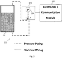
- Fig. 5 shows a pressure sensor configuration 500 in accordance with an embodiment of the disclosure.
- the pressure sensor configuration 500 may be implemented to determine the level, volume and/or mass of liquid in a pressurized liquid (e.g ., cryogenic) storage tank 102.
- a switchable pressure sensor (SPS) unit 510 comprises a pressure sensor 504 that selectively couples to the HI port or the LO port of the tank 102 via pressure piping.
- the pressure sensor 504 is constructed from 316 SST, brass, copper, or anodized aluminum wetted parts with Flourinert fill (or equivalent).
- the SPS unit 510 may utilize a solenoid valve to switch connection of the pressure sensor 504 between the HI port and the LO port (or vice versa) of tank 102.
- the pressure measurements from the pressure sensor 504 are provided to an electronics/communication module 508 (e.g., a remote telemetry unit or "RTU") via electrical wiring.
- the electronics/communication module 508 processes the pressure measurements from the pressure sensor 504 and/or forwards the pressure measurements to a remote computer for processing.
- the cost of pressure sensor configuration 500 is reduced compared to pressure sensor configurations 100, 200, and 400, since only one sensor is used. Further, the pressure sensor configuration 500 is not subject to damage by improper connection to tank 102 as is pressure sensor configuration 300.
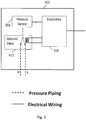
- Fig. 6 shows an SPS unit 600 (e.g ., corresponding to SPS unit 510) in accordance with an embodiment of the disclosure.
- the SPS unit 600 comprises the pressure sensor 504 and a solenoid valve 612 controlled by electronics 608.
- the electronics 608 may correspond to a micro-controller and/or other circuitry.
- the solenoid valve 612 is configured to switch the pressure piping connection for the pressure sensor 504 between a first port (e.g., a HI port) and a second port (e.g., a LO port). In this manner, the pressure sensor 504 is able to provide a reading of the pressure for each of multiple ports of a tank.
- Fig. 7A shows a system 700A in accordance with an embodiment of the disclosure.
- the system 700A comprises a remote telemetry unit (RTU) 740 with an SPS unit.
- the RTU 740 further comprises a manifold (not shown) that enables the RTU 740 to be mounted to a flat surface (e.g., a wall or fence) or a rounded surface ( e.g., a pole or tank exterior).
- the manifold may comprise, for example, an anodized aluminum base with process connections, a solenoid connection, a sensor connection, an electrical connection, threaded mounting holes, and a vent.
- the RTU 740 may further comprise a weatherproof covering (not shown) for its internal components.
- the RTU 740 measures level and pressure for one or more (e.g ., up to 4 tanks for 1 RTU) cryogenic storage tanks.
- the RTU 740 for example, may be modbus® master to sensor inputs.
- the cost of implementing the SPS unit with RTU 740 is significantly lower than implementing a dual sensor configuration (e.g ., pressure sensor configurations 100, 200 and 400), yet it provides both highly accurate level and pressure information. Further, the pressure sensor of the SPS unit is not susceptible to damage by incorrect user connection to tank pressure as are the differential pressure sensors of pressure sensor configurations 100, 200 and 300.
- the RTU 740 couples to a power source 704, which may correspond to a solar panel, a battery and/or an AC power input.
- the RTU 740 communicates with one or more cryogenic tanks 702.
- RTU 740 may receive static pressure inputs from each cryogenic tank 702.
- the RTU 740 may switch the tank port from which the static pressure input is received by controlling a solenoid valve or another switching mechanism. In this manner, the RTU 740 may compute a differential pressure for each cryogenic tank 702 and/or provide the pressure readings needed to calculate the differential pressure to another entity.
- the RTU 740 is configured to compute the volume of liquid in each cryogenic tank 702. This is accomplished based on knowledge of tank size and physical properties of the liquid being stored in each cryogenic tank 702. Various parameters (e.g ., differential pressure, level, volume and/or mass) of liquid in each cryogenic tank 702 may be displayed by the RTU 740 ( e.g., using an LCD or other display). The display of information may be continual or in response to a user request ( e.g ., pushing one or more buttons on the RTU 740).
- Various parameters e.g ., differential pressure, level, volume and/or mass
- the display of information may be continual or in response to a user request (e.g ., pushing one or more buttons on the RTU 740).
- RTU 740 combines up-to-the-minute accuracy in cryogenic product level and pressure measurement with a communications system that optimizes inventory management and product delivery cycles.
- the RTU 740 may, for example, calculate the level of product inside a tank 702 using pressure measurements from its integral sensor and/or 4-20 mA inputs, and store the information in data logs.
- the logged data may be transmitted directly to a user's computer for viewing and/or printing, without requiring downloads from a website or third-party data host.
- built-in alarms for the RTU 740 may alert an operator when a parameter falls below a user-specified threshold (e.g ., when differential pressure or a corresponding volume falls below a predetermined threshold).
- the RTU 740 can provide continuous monitoring and an alarm system to help eliminate the risk of running out of product.
- the RTU 740 also minimizes the need for "extra" product deliveries to ensure that tank levels do not become critically low.
- the RTU 740 is highly practical and cost-efficient.
- Data stored or calculated by the RTU 740 may be transmitted via landline or cellular communications (e.g ., both CSD and GPRS communications are supported) to a remote computing system.
- the system 700A is shown to comprise a computer 708 coupled to the RTU 740 via a modem 706.
- the modem 706 may be, for example, a landline modem or cellular modem.
- the computer 708 comprises a display 710 (e.g., an LCD display), a user interface 730 (e.g., a touchscreen, a touchpad, a keyboard, a mouse and/or other input devices), and RTU software 720 for use with RTU 740.
- the RTU software 720 provides a comprehensive set of controls for configuring RTU 740, customizing data management functions, and generating reports from a single host computer.
- the RTU software 720 supports remote monitoring of tank parameters based on RTU management instructions, modem interface instructions, and a database file.
- the RTU management instructions when executed, enable setup of RTU 740, report generation (tabular and graphical), alarm viewing, alarm acknowledgment, and RTU condition summaries.
- the modem interface instructions when executed, enable communications between computer 708 and RTU 740 via modem 706.
- information received from the RTU 740 is automatically saved to a hard drive or other data storage option for the computer 708.
- the database file stores information such as RTU configurations, customer data, and RTU status information received while the RTU software 720 is executed. Individual RTU data log files may be stored, for example, on a hard drive or other data storage option for the computer 708.
- RTU software 720 Various user functions for the RTU are supported by execution of the RTU software 720.
- Such user function include, but are not limited to, configuring the RTU 740 for GPRS communications, configuring RTU parameters (e.g ., alarm setpoints, datalog intervals), viewing and graphing measurement data (e.g., level, pressure, ambient temperature, values of 4-20 mA and contact inputs, 4-20 mA output values), establishing and maintaining an RTU customer database, storing information (e.g ., setup, user, product, RTU/tank, customer, and input/output information) in a single file on the computer 708, manually polling the RTU 740 (via modem or internet), and configuring automatic polling of RTUs.
- RTU parameters e.g ., alarm setpoints, datalog intervals
- viewing and graphing measurement data e.g., level, pressure, ambient temperature, values of 4-20 mA and contact inputs, 4-20 mA output values
- Polling options include polling all RTUs associated with the RTU software 720, polling an RTU sub-group, or polling based on an RTU characteristic.
- user functions related to the RTU software 720 may further include, but are not limited to, viewing and printing RTU status information, viewing and acknowledging alarms, and printing an alarm history.
- the RTU software 720 implements a security system.
- a three-level security system may be implemented to prevent unauthorized changes to RTU parameters and settings.
- System administrators have full access and can setup and change users and user passwords.
- Senior operators Level B
- Basic operators Level C
- Level C can view screens and current measurements, poll an RTU, and acknowledge alarms.
- the RTU software 720 supports polling communications to and from an RTU. For example, a user can poll a selected RTU manually or poll a group of RTUs automatically in accordance with a pre-set schedule. Once the RTU software 720 connects to an RTU, the RTU software 720 causes any pending configuration changes to the RTU and receives alarm status, captured measurements, and other information stored in the RTU since the last polling. Measurement data received is stored in individual RTU log files on the host PC hard drive or other storage option for the computer 708.
- Fig. 7B shows a system 700B in accordance with another embodiment of the disclosure.
- the system 700B is similar to system 700A, except that RTU 742 does not include the SPS unit as does RTU 740. Instead, RTU 742 couples to SPS unit 744 comprising, for example, a pressure sensor, a solenoid valve, and electronics.
- SPS unit 744 comprising, for example, a pressure sensor, a solenoid valve, and electronics.
- the control features, storage features, logging features, communication features, and other operations of RTU 740 described for system 700A are applicable for RTU 742 of system 700B.
- Fig. 8 shows a method 800 to determine the volume of liquid in a pressurized liquid storage tank in accordance with an embodiment of the disclosure.
- the method 800 comprises receiving a first measurement from a pressure sensor while it is selectively connected to a first port of a tank (block 802).
- the pressure sensor connection is switched from the first port to a second port of the tank.
- a second measurement is received from the pressure sensor while it is selectively connected to a second port of the tank.
- a volume of liquid in the tank is determined based on the first and second measurements (block 808).
- a differential pressure is calculated from the first and second measurements. Then, the level, volume and/or mass is determined using the differential pressure calculation, the tank geometry, and known physical properties of the liquid being stored.
- SPS unit electronics instead of RTU electronics could control switching the solenoid valve and performing calculations such as subtracting pressure sensor measurements to determine level (differential pressure) of a tank.
Landscapes
- Physics & Mathematics (AREA)
- General Physics & Mathematics (AREA)
- Fluid Mechanics (AREA)
- Engineering & Computer Science (AREA)
- Signal Processing (AREA)
- Measuring Fluid Pressure (AREA)
Description
- Pressure sensors have various applications. As an example, pressure sensors have been used to determine parameters (e.g., level, volume, mass) of liquid in a pressurized liquid storage tank.
Figs. 1-4 show various existing pressure sensor configurations for this application. -
Fig. 1 shows apressure sensor configuration 100 comprising a pressurizedtank 102 coupled to apressure sensor 104 and adifferential pressure sensor 106 via pressure piping. Thepressure sensor 104 measures pressure at the top (HI) port of the tank 102 (compared to vacuum or atmospheric pressure) and thedifferential pressure sensor 106 measures a difference in pressure between the HI port and LO port of thetank 102. The pressure measurements from thepressure sensor 104 and thedifferential pressure sensor 106 are provided to an electronics/communication module 108 via electrical wiring. The electronics/communication module 108 processes the pressure measurements from thepressure sensor 104 and thedifferential pressure sensor 106 and/or forwards these pressure measurements to a remote computer for processing. - In
Fig. 2 , apressure sensor configuration 200 is shown with a combo pressure/differential pressure (PDP)sensor 204 coupled to thetank 102 via pressure piping. Thecombo PDP sensor 204 comprises a pressure sensor and a differential pressure sensor integrated into a single unit to reduce cost and complexity. Thecombo PDP sensor 204 measures pressure at the HI port of the tank 102 (compared to vacuum or atmospheric pressure) and measures a difference in pressure between the HI port and the LO port of thetank 102. The pressure measurements from thecombo PDP sensor 204 are provided to an electronics/communication module 208 via electrical wiring. The electronics/communication module 208 processes the pressure measurements from thecombo PDP sensor 204 and/or forwards these pressure measurements to a remote computer for processing. - In
Fig. 3 , apressure sensor configuration 300 is shown with thedifferential pressure sensor 106 coupled to thetank 102 via pressure piping. Thedifferential pressure sensor 106 measures a difference in pressure between the HI port and the LO port of thetank 102. The pressure measurements from thedifferential pressure sensor 106 are provided to an electronics/communication module 308 via electrical wiring. The electronics/communication module 308 processes the pressure measurements from thedifferential pressure sensor 106 and/or forwards the pressure measurements to a remote computer for processing. - In the
pressure sensor configuration 300, thedifferential pressure sensor 106 measures level. This sensor must handle the high static pressure of the tank, but the difference in pressure between the inputs may be limited to a lower pressure (e.g., twice the differential pressure range). This means that if a user connected the HI or LO port on the tank to the transmitter with the other side vented to atmosphere, the sensor would be damaged. Using a more complex differential pressure sensor or separate overpressure device is possible, but increases cost.Sensor configuration 300 is less costly thanconfigurations - In
Fig. 4 , apressure sensor configuration 400 is shown with twopressure sensors tank 102 via pressure piping. There is no differential pressure sensor inpressure sensor configuration 400. However, differential pressure is determinable by subtracting the pressure measurement ofpressure sensor 104A from the pressure measurement ofpressure sensor 104B (or vice versa). Using twopressure sensors pressure sensor configuration 400 significantly magnifies measurement errors that occur due to temperature effect or other ambient effects because eachpressure sensor tank 102, EHI is the measurement error in PHI, PLO is the pressure at the LO port of thetank 102, and ELO is the measurement error in PLO. If EHI, and ELO are large and in opposite directions, the accuracy of the differential pressure calculation suffers. The pressure measurements from thepressure sensors communication module 408 via electrical wiring. The electronics/communication module 408 processes the pressure measurements from thepressure sensors -
- In at least some embodiments, a pressure sensor configuration includes a pressure sensor and a switchable valve coupled to the pressure sensor. The switchable valve enables the pressure sensor to measure pressure at multiple ports of a pressurized tank.
- A remote telemetry unit (RTU) includes a pressure sensor and a solenoid valve coupled to the pressure sensor. The RTU operates the solenoid valve in conjunction with measurements of the pressure sensor to determine a differential pressure of a pressurized tank.
- A method includes receiving, by an RTU, a first measurement from a pressure sensor while connected to a first pressure pipe connection. The method also includes receiving, by the RTU, a second measurement from the pressure sensor while connected to a second pressure pipe connection. The method also includes calculating, by the RTU, a differential pressure based on the first and second measurements.
- For a more detailed description of the embodiments, reference will now be made to the following accompanying drawings:
-
Figs. 1-4 show various existing pressure sensor configurations; -
Fig. 5 shows a pressure sensor configuration in accordance with an embodiment of the disclosure; -
Fig. 6 shows a switchable pressure sensor (SPS) unit in accordance with an embodiment of the disclosure; -
Figs. 7A-7B show systems in accordance with an embodiment of the disclosure; and -
Fig. 8 shows a method to determine a volume of liquid in a pressurized liquid storage tank in accordance with an embodiment of the disclosure. - In the drawings and description that follows, like parts are marked throughout the specification and drawings with the same reference numerals, respectively. The drawing figures are not necessarily to scale. Certain features of the invention may be shown exaggerated in scale or in somewhat schematic.
-
Fig. 5 shows apressure sensor configuration 500 in accordance with an embodiment of the disclosure. For example, thepressure sensor configuration 500 may be implemented to determine the level, volume and/or mass of liquid in a pressurized liquid (e.g., cryogenic)storage tank 102. Inconfiguration 500, a switchable pressure sensor (SPS)unit 510 comprises apressure sensor 504 that selectively couples to the HI port or the LO port of thetank 102 via pressure piping. Thepressure sensor 504 is constructed from 316 SST, brass, copper, or anodized aluminum wetted parts with Flourinert fill (or equivalent). TheSPS unit 510 may utilize a solenoid valve to switch connection of thepressure sensor 504 between the HI port and the LO port (or vice versa) oftank 102. - The pressure measurements from the
pressure sensor 504 are provided to an electronics/communication module 508 (e.g., a remote telemetry unit or "RTU") via electrical wiring. The electronics/communication module 508 processes the pressure measurements from thepressure sensor 504 and/or forwards the pressure measurements to a remote computer for processing. For example, the differential pressure (the level) fortank 102 may be calculated as: DP = PHI + EHI - (PLO + ELO), where PHI is the pressure at the HI port of thetank 102, EHI is the measurement error in PHI, PLO is the pressure at the LO port of thetank 102, and ELO is the measurement error in PLO. Because thesame pressure sensor 504 is used to determine PHI and PLO, the error in the DP calculation cancels out and accuracy improves. - In addition to providing an accurate level calculation for the
tank 102, the cost ofpressure sensor configuration 500 is reduced compared topressure sensor configurations pressure sensor configuration 500 is not subject to damage by improper connection totank 102 as ispressure sensor configuration 300. -
Fig. 6 shows an SPS unit 600 (e.g., corresponding to SPS unit 510) in accordance with an embodiment of the disclosure. TheSPS unit 600 comprises thepressure sensor 504 and asolenoid valve 612 controlled byelectronics 608. Theelectronics 608 may correspond to a micro-controller and/or other circuitry. In response to a control signal from theelectronics 608, thesolenoid valve 612 is configured to switch the pressure piping connection for thepressure sensor 504 between a first port (e.g., a HI port) and a second port (e.g., a LO port). In this manner, thepressure sensor 504 is able to provide a reading of the pressure for each of multiple ports of a tank. -
Fig. 7A shows asystem 700A in accordance with an embodiment of the disclosure. As shown, thesystem 700A comprises a remote telemetry unit (RTU) 740 with an SPS unit. In at least some embodiments, theRTU 740 further comprises a manifold (not shown) that enables theRTU 740 to be mounted to a flat surface (e.g., a wall or fence) or a rounded surface (e.g., a pole or tank exterior). The manifold may comprise, for example, an anodized aluminum base with process connections, a solenoid connection, a sensor connection, an electrical connection, threaded mounting holes, and a vent. TheRTU 740 may further comprise a weatherproof covering (not shown) for its internal components. In at least some embodiments, theRTU 740 measures level and pressure for one or more (e.g., up to 4 tanks for 1 RTU) cryogenic storage tanks. TheRTU 740, for example, may be modbus® master to sensor inputs. - The cost of implementing the SPS unit with
RTU 740 is significantly lower than implementing a dual sensor configuration (e.g.,pressure sensor configurations pressure sensor configurations - As shown, the
RTU 740 couples to apower source 704, which may correspond to a solar panel, a battery and/or an AC power input. Insystem 700A, theRTU 740 communicates with one or morecryogenic tanks 702. For example,RTU 740 may receive static pressure inputs from eachcryogenic tank 702. Further, theRTU 740 may switch the tank port from which the static pressure input is received by controlling a solenoid valve or another switching mechanism. In this manner, theRTU 740 may compute a differential pressure for eachcryogenic tank 702 and/or provide the pressure readings needed to calculate the differential pressure to another entity. - In at least some embodiments, the
RTU 740 is configured to compute the volume of liquid in eachcryogenic tank 702. This is accomplished based on knowledge of tank size and physical properties of the liquid being stored in eachcryogenic tank 702. Various parameters (e.g., differential pressure, level, volume and/or mass) of liquid in eachcryogenic tank 702 may be displayed by the RTU 740 (e.g., using an LCD or other display). The display of information may be continual or in response to a user request (e.g., pushing one or more buttons on the RTU 740). - In at least some embodiments,
RTU 740 combines up-to-the-minute accuracy in cryogenic product level and pressure measurement with a communications system that optimizes inventory management and product delivery cycles. TheRTU 740 may, for example, calculate the level of product inside atank 702 using pressure measurements from its integral sensor and/or 4-20 mA inputs, and store the information in data logs. The logged data may be transmitted directly to a user's computer for viewing and/or printing, without requiring downloads from a website or third-party data host. Further, built-in alarms for theRTU 740 may alert an operator when a parameter falls below a user-specified threshold (e.g., when differential pressure or a corresponding volume falls below a predetermined threshold). An operator can also run a status report "on demand" for instantaneous data monitoring. Thus, theRTU 740 can provide continuous monitoring and an alarm system to help eliminate the risk of running out of product. TheRTU 740 also minimizes the need for "extra" product deliveries to ensure that tank levels do not become critically low. For scenarios where multiple chemicals and/or multiple storage sites are managed and/or scenarios where a constant supply of cryogenic gas is critical (e.g., healthcare services), theRTU 740 is highly practical and cost-efficient. Data stored or calculated by the RTU 740 (tank level and pressure measurements) may be transmitted via landline or cellular communications (e.g., both CSD and GPRS communications are supported) to a remote computing system. - As an example, the
system 700A is shown to comprise acomputer 708 coupled to theRTU 740 via amodem 706. Themodem 706 may be, for example, a landline modem or cellular modem. Thecomputer 708 comprises a display 710 (e.g., an LCD display), a user interface 730 (e.g., a touchscreen, a touchpad, a keyboard, a mouse and/or other input devices), andRTU software 720 for use withRTU 740. In at least some embodiments, theRTU software 720 provides a comprehensive set of controls for configuringRTU 740, customizing data management functions, and generating reports from a single host computer. - In at least some embodiments, the
RTU software 720 supports remote monitoring of tank parameters based on RTU management instructions, modem interface instructions, and a database file. The RTU management instructions, when executed, enable setup ofRTU 740, report generation (tabular and graphical), alarm viewing, alarm acknowledgment, and RTU condition summaries. The modem interface instructions, when executed, enable communications betweencomputer 708 andRTU 740 viamodem 706. In at least some embodiments, information received from theRTU 740 is automatically saved to a hard drive or other data storage option for thecomputer 708. The database file stores information such as RTU configurations, customer data, and RTU status information received while theRTU software 720 is executed. Individual RTU data log files may be stored, for example, on a hard drive or other data storage option for thecomputer 708. - Various user functions for the RTU are supported by execution of the
RTU software 720. Such user function include, but are not limited to, configuring theRTU 740 for GPRS communications, configuring RTU parameters (e.g., alarm setpoints, datalog intervals), viewing and graphing measurement data (e.g., level, pressure, ambient temperature, values of 4-20 mA and contact inputs, 4-20 mA output values), establishing and maintaining an RTU customer database, storing information (e.g., setup, user, product, RTU/tank, customer, and input/output information) in a single file on thecomputer 708, manually polling the RTU 740 (via modem or internet), and configuring automatic polling of RTUs. Polling options include polling all RTUs associated with theRTU software 720, polling an RTU sub-group, or polling based on an RTU characteristic. In some embodiments, user functions related to theRTU software 720 may further include, but are not limited to, viewing and printing RTU status information, viewing and acknowledging alarms, and printing an alarm history. - In some embodiments, the
RTU software 720 implements a security system. For example, a three-level security system may be implemented to prevent unauthorized changes to RTU parameters and settings. System administrators (Level A) have full access and can setup and change users and user passwords. Senior operators (Level B) can add/configure RTUs, acknowledge alarms, and change commonly used parameters. Basic operators (Level C) can view screens and current measurements, poll an RTU, and acknowledge alarms. - In at least some embodiments, the
RTU software 720 supports polling communications to and from an RTU. For example, a user can poll a selected RTU manually or poll a group of RTUs automatically in accordance with a pre-set schedule. Once theRTU software 720 connects to an RTU, theRTU software 720 causes any pending configuration changes to the RTU and receives alarm status, captured measurements, and other information stored in the RTU since the last polling. Measurement data received is stored in individual RTU log files on the host PC hard drive or other storage option for thecomputer 708. -
Fig. 7B shows asystem 700B in accordance with another embodiment of the disclosure. Thesystem 700B is similar tosystem 700A, except thatRTU 742 does not include the SPS unit as doesRTU 740. Instead,RTU 742 couples toSPS unit 744 comprising, for example, a pressure sensor, a solenoid valve, and electronics. The control features, storage features, logging features, communication features, and other operations ofRTU 740 described forsystem 700A are applicable forRTU 742 ofsystem 700B. -
Fig. 8 shows amethod 800 to determine the volume of liquid in a pressurized liquid storage tank in accordance with an embodiment of the disclosure. Themethod 800 comprises receiving a first measurement from a pressure sensor while it is selectively connected to a first port of a tank (block 802). Atblock 804, the pressure sensor connection is switched from the first port to a second port of the tank. Atblock 806, a second measurement is received from the pressure sensor while it is selectively connected to a second port of the tank. A volume of liquid in the tank is determined based on the first and second measurements (block 808). To determine the level, volume or mass of liquid, a differential pressure is calculated from the first and second measurements. Then, the level, volume and/or mass is determined using the differential pressure calculation, the tank geometry, and known physical properties of the liquid being stored. - While preferred embodiments of this invention have been shown and described, modifications thereof can be made by one skilled in the art without departing from the scope or teaching of this invention. The embodiments described herein are exemplary only and are not limiting. Many variations and modifications of the system and apparatus are possible and are within the scope of the invention. For example, SPS unit electronics (instead of RTU electronics) could control switching the solenoid valve and performing calculations such as subtracting pressure sensor measurements to determine level (differential pressure) of a tank.
- For example, the relative dimensions of various parts, the materials from which the various parts are made, and other parameters can be varied, so long as the override apparatus retain the advantages discussed herein. Accordingly, the scope of protection is not limited to the embodiments described herein, but is only limited by the claims that follow, the scope of which shall include all equivalents of the subject matter of the claims.
Claims (13)
- A pressure sensor configuration (500), comprising:a pressure sensor (504);a switchable valve coupled to the pressure sensor (500), the switchable valve enabling the pressure sensor (504) to measure pressure at multiple ports of a pressurized tank (102); anda controller (508) in communication with the pressure sensor (504), wherein the controller (508) is configured to receive pressure measurements at the multiple ports from the pressure sensor (504) and to calculate a differential pressure for the pressurized tank (102) with the error in the differential pressure calculation cancelling out.
- The pressure sensor configuration (500) of claim 1 wherein the switchable valve comprises a solenoid valve (612).
- The pressure sensor configuration (500) of claim 1, wherein the controller (508) is configured to store the pressure measurements.
- The pressure sensor configuration (500) of claim 1, wherein the controller (508) is configured to calculate a volume of liquid for the pressurized tank (102).
- The pressure sensor configuration (500) of claim 1 further comprising the controller (508) being in communication with the switchable valve, wherein the controller (508) is configured to selectively direct the switchable valve to switch between a first pressure piping connection and a second pressure piping connection.
- The pressure sensor configuration (500) of claim 1, wherein the controller (508) is configured to calculate the differential pressure between HI and LO ports of the pressurized tank (102) based on measurements from the pressure sensor (504) and to transmit the calculated differential pressure to a remote computing system.
- The pressure sensor configuration of claim 6 wherein the controller (508) is configured to calculate a volume of liquid stored by the pressurized tank (102) based on the differential pressure calculation and to transmit the calculated volume to a remote computing system.
- The pressure sensor configuration (500) of claim 1 wherein the pressure sensor configuration (500) is part of a switchable pressure sensor (SPS) unit (510) with electronics to control the switchable valve and determine a differential pressure for the pressurized tank (102).
- The pressure sensor configuration (500) of claim 1 wherein the pressure sensor configuration (500) is part of a remote telemetry unit (RTU) (740) with electronics to control the switchable valve and determine a differential pressure for the pressurized tank (102).
- A method, comprising:receiving, by a switchable pressure sensor (SPS) unit (510), a first measurement from a pressure sensor (504) while connected to a first pressure pipe connection;receiving, by the SPS unit (510), a second measurement from the pressure sensor (504) while connected to a second pressure pipe connection; andcalculating a differential pressure based on the first and second measurements such that the error in the differential pressure calculation cancels out.
- The method of claim 10 wherein said calculating is performed by the SPS unit (510).
- The method of claim 10 wherein said calculating is performed by a remote telemetry unit (RTU) (740) in communication with the SPS unit (510).
- The method of claim 10 wherein switching the pressure sensor connection comprises operating a solenoid valve (612) after the first measurement and before the second measurement.
Applications Claiming Priority (2)
| Application Number | Priority Date | Filing Date | Title |
|---|---|---|---|
| US12/884,757 US8464590B2 (en) | 2010-09-17 | 2010-09-17 | Pressure sensor configuration for pressurized tank |
| PCT/US2011/048551 WO2012036842A2 (en) | 2010-09-17 | 2011-08-22 | Pressure sensor configuration for pressurized tank |
Publications (3)
| Publication Number | Publication Date |
|---|---|
| EP2616789A2 EP2616789A2 (en) | 2013-07-24 |
| EP2616789A4 EP2616789A4 (en) | 2014-07-30 |
| EP2616789B1 true EP2616789B1 (en) | 2019-09-25 |
Family
ID=45816509
Family Applications (1)
| Application Number | Title | Priority Date | Filing Date |
|---|---|---|---|
| EP11825625.4A Active EP2616789B1 (en) | 2010-09-17 | 2011-08-22 | Pressure sensor configuration for pressurized tank |
Country Status (5)
| Country | Link |
|---|---|
| US (1) | US8464590B2 (en) |
| EP (1) | EP2616789B1 (en) |
| CN (1) | CN103221796A (en) |
| BR (1) | BR112013006319A2 (en) |
| WO (1) | WO2012036842A2 (en) |
Families Citing this family (14)
| Publication number | Priority date | Publication date | Assignee | Title |
|---|---|---|---|---|
| DE102009026592B4 (en) | 2009-05-29 | 2014-08-28 | Sorin Group Deutschland Gmbh | Device for determining the venous inflow to a blood reservoir of an extracorporeal blood circulation |
| EP2754458B1 (en) | 2011-07-12 | 2017-02-01 | Sorin Group Italia S.r.l. | Dual chamber blood reservoir |
| US10001313B2 (en) * | 2013-09-09 | 2018-06-19 | Inovatzia, Inc. | Reusable cryogenic carrying case for biological materials |
| US10458833B2 (en) * | 2014-05-16 | 2019-10-29 | Sorin Group Italia S.R.L. | Blood reservoir with fluid volume measurement based on pressure sensor |
| GB2546271A (en) * | 2016-01-12 | 2017-07-19 | Linde Ag | A cylinder for pressurised liquefied gas and a method of calculating the liquid volume |
| TWI618995B (en) * | 2016-04-18 | 2018-03-21 | Kita Sensor Tech Co Ltd | Pressure sensor and control system |
| US11519772B2 (en) * | 2018-08-25 | 2022-12-06 | Evigia Systems, Inc. | Liquid pressure and level sensor systems and sensors, methods, and applications therefor |
| DE102018129139A1 (en) * | 2018-11-20 | 2020-05-20 | Miele & Cie. Kg | Device and method for determining a fill level of a liquid in a container of a vending machine and vending machine |
| US11215492B2 (en) * | 2018-11-26 | 2022-01-04 | Analysis And Measurement Services Corporation | Differential pressure based level measurement systems and methods |
| CN109540256A (en) * | 2018-11-28 | 2019-03-29 | 福建师范大学 | A kind of solar heating engineering water-level detecting device and its detection method |
| FR3099247B1 (en) * | 2019-07-26 | 2022-07-15 | D Innovation | Level measuring device |
| US11885728B2 (en) * | 2020-12-23 | 2024-01-30 | Battelle Energy Alliance, Llc | Mass measurement systems and related methods for measuring mass of solids within a liquid |
| FR3126244B1 (en) * | 2021-08-17 | 2023-12-29 | Safran Helicopter Engines | Sensor for determining a liquid level for an aircraft tank, assembly of a tank and a sensor, method of using such a sensor |
| GB2630358A (en) * | 2023-05-25 | 2024-11-27 | Airbus Operations Ltd | Fuel tank monitoring system |
Family Cites Families (25)
| Publication number | Priority date | Publication date | Assignee | Title |
|---|---|---|---|---|
| US3999435A (en) * | 1975-04-24 | 1976-12-28 | Fischer & Porter Co. | Differential pressure transmitter |
| GB2186317B (en) * | 1986-02-11 | 1990-03-21 | Tankmaster Ltd | Improvements in tank contents measurement |
| JPS6416946A (en) * | 1987-07-13 | 1989-01-20 | Mitsubishi Electric Corp | Pressure detecting device |
| US5309764A (en) | 1993-05-26 | 1994-05-10 | Itt Corporation | Tank gauging system |
| US5718210A (en) * | 1995-07-31 | 1998-02-17 | Toyota Jidosha Kabushiki Kaisha | Testing apparatus for fuel vapor treating device |
| JP3239701B2 (en) * | 1995-07-31 | 2001-12-17 | トヨタ自動車株式会社 | Failure diagnosis device for fuel vapor processing unit |
| US5780729A (en) * | 1996-07-24 | 1998-07-14 | The United States Of America As Represented By The Secretary Of The Navy | Fuel delivery system |
| US6435164B1 (en) * | 2000-12-07 | 2002-08-20 | Ford Global Technologies, Inc. | Fuel weathering method for vehicle evaporative emission system |
| US6542848B1 (en) | 2000-07-31 | 2003-04-01 | Chart Inc. | Differential pressure gauge for cryogenic fluids |
| US6434772B1 (en) | 2000-10-24 | 2002-08-20 | U.N.X. Incorporated | Chemical dispensing system |
| JP3849916B2 (en) * | 2001-04-06 | 2006-11-22 | 日野自動車株式会社 | Exhaust pressure measuring device |
| US6675641B2 (en) * | 2001-06-21 | 2004-01-13 | Caterpillar Inc | Closed system transient diesel fuel conditioning and measurement system |
| WO2004072586A2 (en) * | 2003-02-10 | 2004-08-26 | Sheldon Michael L | Measuring fluid volumes in a container using pressure |
| DE10330414B4 (en) * | 2003-07-04 | 2008-06-05 | Continental Aktiengesellschaft | Method for measuring a pressure |
| JP2005076469A (en) * | 2003-08-28 | 2005-03-24 | Fuji Heavy Ind Ltd | Diagnostic apparatus and diagnostic method for evaporative fuel treatment system |
| JP4389013B2 (en) * | 2003-08-28 | 2009-12-24 | 富士重工業株式会社 | Diagnostic apparatus and diagnostic method for evaporative fuel treatment system |
| DE10351893A1 (en) * | 2003-11-06 | 2005-06-09 | Robert Bosch Gmbh | Method for operating an internal combustion engine |
| US7266986B2 (en) | 2003-11-19 | 2007-09-11 | The United States Of America As Represented By The Secretary Of The Army | Portable system for measuring dynamic pressure in situ and method of employment therefor |
| JP4481054B2 (en) * | 2004-03-26 | 2010-06-16 | 富士重工業株式会社 | Evaporative fuel processing system diagnostic device |
| JP4260079B2 (en) | 2004-08-06 | 2009-04-30 | 株式会社日本自動車部品総合研究所 | Fuel property measuring apparatus for internal combustion engine and internal combustion engine |
| JP4238835B2 (en) * | 2005-03-18 | 2009-03-18 | トヨタ自動車株式会社 | Automobile and control method thereof |
| GB0526330D0 (en) * | 2005-12-23 | 2006-02-01 | Rolls Royce Plc | Engine health monitoring |
| US7805259B2 (en) * | 2006-01-13 | 2010-09-28 | Cosmo Instruments Co., Ltd. | Method for detecting an operation malfunction of a leakage inspector, and a leakage inspector having a function to detect an operation malfunction thereof |
| CN101474451A (en) * | 2009-01-20 | 2009-07-08 | 张培林 | Oxygen concentration control device of intelligent type breathing machine |
| US8166795B2 (en) * | 2009-11-30 | 2012-05-01 | Eaton Corporation | Out-of-range sensor recalibration |
-
2010
- 2010-09-17 US US12/884,757 patent/US8464590B2/en not_active Expired - Fee Related
-
2011
- 2011-08-22 WO PCT/US2011/048551 patent/WO2012036842A2/en not_active Ceased
- 2011-08-22 BR BR112013006319A patent/BR112013006319A2/en not_active IP Right Cessation
- 2011-08-22 CN CN201180055194XA patent/CN103221796A/en active Pending
- 2011-08-22 EP EP11825625.4A patent/EP2616789B1/en active Active
Non-Patent Citations (1)
| Title |
|---|
| None * |
Also Published As
| Publication number | Publication date |
|---|---|
| WO2012036842A3 (en) | 2012-05-18 |
| CN103221796A (en) | 2013-07-24 |
| US20120067133A1 (en) | 2012-03-22 |
| EP2616789A4 (en) | 2014-07-30 |
| BR112013006319A2 (en) | 2016-06-21 |
| WO2012036842A2 (en) | 2012-03-22 |
| US8464590B2 (en) | 2013-06-18 |
| EP2616789A2 (en) | 2013-07-24 |
Similar Documents
| Publication | Publication Date | Title |
|---|---|---|
| US8464590B2 (en) | Pressure sensor configuration for pressurized tank | |
| US9352951B2 (en) | Fuel delivery management system | |
| US20200159258A1 (en) | Remote control of fluid-handling devices | |
| US20210123443A1 (en) | Real-time pump monitoring with prescriptive analytics | |
| US20210286383A1 (en) | Liquid handling system monitoring systems and methods | |
| KR101778333B1 (en) | PLC System | |
| US7308825B2 (en) | Tank gauging system | |
| EP3992459A1 (en) | Liquid resistant pump, pump housing, and controls and methods of making and use thereof | |
| CN101382858B (en) | Calibrating method and apparatus for touch screen equipment | |
| CN101395452A (en) | Transmitter with detachable local operator interface | |
| CN107576370A (en) | A kind of external labeling type liquid level checking method of redundancy | |
| US20180278628A1 (en) | Non-contact cybersecurity monitoring device | |
| SE0850069A1 (en) | Procedure for remote monitoring of storage tanks for pressurized beer | |
| TWM611799U (en) | Level sensor system | |
| CN205787806U (en) | A kind of gas station tank field comprehensive monitoring system | |
| US12181901B2 (en) | Automated tank systems and methods for use in oil and gas extraction operation | |
| EP3679331A1 (en) | Tank volume monitoring using sensed fluid pressure | |
| EP3715973B1 (en) | Anomaly detection method and system for process instrument, and plc | |
| KR20150115603A (en) | Temperature and humidity remote control method | |
| CN211042407U (en) | Non-contact ultrasonic liquid level sensor and system thereof | |
| US12241563B1 (en) | Water supply monitoring and control system | |
| TR2025017654U5 (en) | IMPROVEMENT IN VORTEX FLOWMETER WITH REMOTE FAULT DETECTION | |
| KR101810178B1 (en) | Digital indicator apparatus and method performing thereof | |
| WO2024197089A2 (en) | Smart cap device for container systems | |
| TR202008558A2 (en) | A MEASURING DEVICE |
Legal Events
| Date | Code | Title | Description |
|---|---|---|---|
| PUAI | Public reference made under article 153(3) epc to a published international application that has entered the european phase |
Free format text: ORIGINAL CODE: 0009012 |
|
| 17P | Request for examination filed |
Effective date: 20130404 |
|
| AK | Designated contracting states |
Kind code of ref document: A2 Designated state(s): AL AT BE BG CH CY CZ DE DK EE ES FI FR GB GR HR HU IE IS IT LI LT LU LV MC MK MT NL NO PL PT RO RS SE SI SK SM TR |
|
| DAX | Request for extension of the european patent (deleted) | ||
| A4 | Supplementary search report drawn up and despatched |
Effective date: 20140701 |
|
| RIC1 | Information provided on ipc code assigned before grant |
Ipc: G01F 1/34 20060101ALI20140625BHEP Ipc: G01F 23/14 20060101ALI20140625BHEP Ipc: G01F 22/02 20060101ALI20140625BHEP Ipc: G01F 23/00 20060101ALI20140625BHEP Ipc: G01L 19/00 20060101AFI20140625BHEP Ipc: G01F 23/16 20060101ALI20140625BHEP Ipc: G01L 15/00 20060101ALI20140625BHEP Ipc: G01L 13/00 20060101ALI20140625BHEP Ipc: G01F 23/18 20060101ALI20140625BHEP |
|
| RAP1 | Party data changed (applicant data changed or rights of an application transferred) |
Owner name: CAMERON TECHNOLOGIES LIMITED |
|
| GRAP | Despatch of communication of intention to grant a patent |
Free format text: ORIGINAL CODE: EPIDOSNIGR1 |
|
| STAA | Information on the status of an ep patent application or granted ep patent |
Free format text: STATUS: GRANT OF PATENT IS INTENDED |
|
| INTG | Intention to grant announced |
Effective date: 20190503 |
|
| GRAS | Grant fee paid |
Free format text: ORIGINAL CODE: EPIDOSNIGR3 |
|
| GRAA | (expected) grant |
Free format text: ORIGINAL CODE: 0009210 |
|
| STAA | Information on the status of an ep patent application or granted ep patent |
Free format text: STATUS: THE PATENT HAS BEEN GRANTED |
|
| AK | Designated contracting states |
Kind code of ref document: B1 Designated state(s): AL AT BE BG CH CY CZ DE DK EE ES FI FR GB GR HR HU IE IS IT LI LT LU LV MC MK MT NL NO PL PT RO RS SE SI SK SM TR |
|
| REG | Reference to a national code |
Ref country code: GB Ref legal event code: FG4D |
|
| REG | Reference to a national code |
Ref country code: CH Ref legal event code: EP |
|
| REG | Reference to a national code |
Ref country code: DE Ref legal event code: R096 Ref document number: 602011062359 Country of ref document: DE |
|
| REG | Reference to a national code |
Ref country code: AT Ref legal event code: REF Ref document number: 1184271 Country of ref document: AT Kind code of ref document: T Effective date: 20191015 |
|
| REG | Reference to a national code |
Ref country code: IE Ref legal event code: FG4D |
|
| REG | Reference to a national code |
Ref country code: NL Ref legal event code: FP |
|
| PG25 | Lapsed in a contracting state [announced via postgrant information from national office to epo] |
Ref country code: FI Free format text: LAPSE BECAUSE OF FAILURE TO SUBMIT A TRANSLATION OF THE DESCRIPTION OR TO PAY THE FEE WITHIN THE PRESCRIBED TIME-LIMIT Effective date: 20190925 Ref country code: LT Free format text: LAPSE BECAUSE OF FAILURE TO SUBMIT A TRANSLATION OF THE DESCRIPTION OR TO PAY THE FEE WITHIN THE PRESCRIBED TIME-LIMIT Effective date: 20190925 Ref country code: HR Free format text: LAPSE BECAUSE OF FAILURE TO SUBMIT A TRANSLATION OF THE DESCRIPTION OR TO PAY THE FEE WITHIN THE PRESCRIBED TIME-LIMIT Effective date: 20190925 Ref country code: SE Free format text: LAPSE BECAUSE OF FAILURE TO SUBMIT A TRANSLATION OF THE DESCRIPTION OR TO PAY THE FEE WITHIN THE PRESCRIBED TIME-LIMIT Effective date: 20190925 Ref country code: BG Free format text: LAPSE BECAUSE OF FAILURE TO SUBMIT A TRANSLATION OF THE DESCRIPTION OR TO PAY THE FEE WITHIN THE PRESCRIBED TIME-LIMIT Effective date: 20191225 |
|
| REG | Reference to a national code |
Ref country code: LT Ref legal event code: MG4D |
|
| REG | Reference to a national code |
Ref country code: NO Ref legal event code: T2 Effective date: 20190925 |
|
| PG25 | Lapsed in a contracting state [announced via postgrant information from national office to epo] |
Ref country code: RS Free format text: LAPSE BECAUSE OF FAILURE TO SUBMIT A TRANSLATION OF THE DESCRIPTION OR TO PAY THE FEE WITHIN THE PRESCRIBED TIME-LIMIT Effective date: 20190925 Ref country code: LV Free format text: LAPSE BECAUSE OF FAILURE TO SUBMIT A TRANSLATION OF THE DESCRIPTION OR TO PAY THE FEE WITHIN THE PRESCRIBED TIME-LIMIT Effective date: 20190925 Ref country code: GR Free format text: LAPSE BECAUSE OF FAILURE TO SUBMIT A TRANSLATION OF THE DESCRIPTION OR TO PAY THE FEE WITHIN THE PRESCRIBED TIME-LIMIT Effective date: 20191226 |
|
| RAP2 | Party data changed (patent owner data changed or rights of a patent transferred) |
Owner name: SENSIA NETHERLANDS B.V. |
|
| REG | Reference to a national code |
Ref country code: AT Ref legal event code: MK05 Ref document number: 1184271 Country of ref document: AT Kind code of ref document: T Effective date: 20190925 |
|
| REG | Reference to a national code |
Ref country code: DE Ref legal event code: R081 Ref document number: 602011062359 Country of ref document: DE Owner name: SENSIA NETHERLANDS B.V., NL Free format text: FORMER OWNER: CAMERON TECHNOLOGIES LIMITED, THE HAGUE, NL |
|
| PG25 | Lapsed in a contracting state [announced via postgrant information from national office to epo] |
Ref country code: PL Free format text: LAPSE BECAUSE OF FAILURE TO SUBMIT A TRANSLATION OF THE DESCRIPTION OR TO PAY THE FEE WITHIN THE PRESCRIBED TIME-LIMIT Effective date: 20190925 Ref country code: EE Free format text: LAPSE BECAUSE OF FAILURE TO SUBMIT A TRANSLATION OF THE DESCRIPTION OR TO PAY THE FEE WITHIN THE PRESCRIBED TIME-LIMIT Effective date: 20190925 Ref country code: AT Free format text: LAPSE BECAUSE OF FAILURE TO SUBMIT A TRANSLATION OF THE DESCRIPTION OR TO PAY THE FEE WITHIN THE PRESCRIBED TIME-LIMIT Effective date: 20190925 Ref country code: IT Free format text: LAPSE BECAUSE OF FAILURE TO SUBMIT A TRANSLATION OF THE DESCRIPTION OR TO PAY THE FEE WITHIN THE PRESCRIBED TIME-LIMIT Effective date: 20190925 Ref country code: RO Free format text: LAPSE BECAUSE OF FAILURE TO SUBMIT A TRANSLATION OF THE DESCRIPTION OR TO PAY THE FEE WITHIN THE PRESCRIBED TIME-LIMIT Effective date: 20190925 Ref country code: ES Free format text: LAPSE BECAUSE OF FAILURE TO SUBMIT A TRANSLATION OF THE DESCRIPTION OR TO PAY THE FEE WITHIN THE PRESCRIBED TIME-LIMIT Effective date: 20190925 Ref country code: AL Free format text: LAPSE BECAUSE OF FAILURE TO SUBMIT A TRANSLATION OF THE DESCRIPTION OR TO PAY THE FEE WITHIN THE PRESCRIBED TIME-LIMIT Effective date: 20190925 Ref country code: PT Free format text: LAPSE BECAUSE OF FAILURE TO SUBMIT A TRANSLATION OF THE DESCRIPTION OR TO PAY THE FEE WITHIN THE PRESCRIBED TIME-LIMIT Effective date: 20200127 |
|
| PG25 | Lapsed in a contracting state [announced via postgrant information from national office to epo] |
Ref country code: CZ Free format text: LAPSE BECAUSE OF FAILURE TO SUBMIT A TRANSLATION OF THE DESCRIPTION OR TO PAY THE FEE WITHIN THE PRESCRIBED TIME-LIMIT Effective date: 20190925 Ref country code: SM Free format text: LAPSE BECAUSE OF FAILURE TO SUBMIT A TRANSLATION OF THE DESCRIPTION OR TO PAY THE FEE WITHIN THE PRESCRIBED TIME-LIMIT Effective date: 20190925 Ref country code: SK Free format text: LAPSE BECAUSE OF FAILURE TO SUBMIT A TRANSLATION OF THE DESCRIPTION OR TO PAY THE FEE WITHIN THE PRESCRIBED TIME-LIMIT Effective date: 20190925 Ref country code: IS Free format text: LAPSE BECAUSE OF FAILURE TO SUBMIT A TRANSLATION OF THE DESCRIPTION OR TO PAY THE FEE WITHIN THE PRESCRIBED TIME-LIMIT Effective date: 20200224 |
|
| REG | Reference to a national code |
Ref country code: GB Ref legal event code: 732E Free format text: REGISTERED BETWEEN 20200528 AND 20200603 |
|
| REG | Reference to a national code |
Ref country code: DE Ref legal event code: R097 Ref document number: 602011062359 Country of ref document: DE |
|
| REG | Reference to a national code |
Ref country code: NL Ref legal event code: PD Owner name: SENSIA NETHERLANDS B.V.; NL Free format text: DETAILS ASSIGNMENT: CHANGE OF OWNER(S), ASSIGNMENT; FORMER OWNER NAME: CAMERON TECHNOLOGIES LIMITED Effective date: 20200609 |
|
| PG2D | Information on lapse in contracting state deleted |
Ref country code: IS |
|
| PG25 | Lapsed in a contracting state [announced via postgrant information from national office to epo] |
Ref country code: IS Free format text: LAPSE BECAUSE OF FAILURE TO SUBMIT A TRANSLATION OF THE DESCRIPTION OR TO PAY THE FEE WITHIN THE PRESCRIBED TIME-LIMIT Effective date: 20200126 Ref country code: DK Free format text: LAPSE BECAUSE OF FAILURE TO SUBMIT A TRANSLATION OF THE DESCRIPTION OR TO PAY THE FEE WITHIN THE PRESCRIBED TIME-LIMIT Effective date: 20190925 |
|
| PLBE | No opposition filed within time limit |
Free format text: ORIGINAL CODE: 0009261 |
|
| STAA | Information on the status of an ep patent application or granted ep patent |
Free format text: STATUS: NO OPPOSITION FILED WITHIN TIME LIMIT |
|
| 26N | No opposition filed |
Effective date: 20200626 |
|
| PG25 | Lapsed in a contracting state [announced via postgrant information from national office to epo] |
Ref country code: SI Free format text: LAPSE BECAUSE OF FAILURE TO SUBMIT A TRANSLATION OF THE DESCRIPTION OR TO PAY THE FEE WITHIN THE PRESCRIBED TIME-LIMIT Effective date: 20190925 |
|
| PG25 | Lapsed in a contracting state [announced via postgrant information from national office to epo] |
Ref country code: MC Free format text: LAPSE BECAUSE OF FAILURE TO SUBMIT A TRANSLATION OF THE DESCRIPTION OR TO PAY THE FEE WITHIN THE PRESCRIBED TIME-LIMIT Effective date: 20190925 |
|
| REG | Reference to a national code |
Ref country code: CH Ref legal event code: PL |
|
| PG25 | Lapsed in a contracting state [announced via postgrant information from national office to epo] |
Ref country code: CH Free format text: LAPSE BECAUSE OF NON-PAYMENT OF DUE FEES Effective date: 20200831 Ref country code: LI Free format text: LAPSE BECAUSE OF NON-PAYMENT OF DUE FEES Effective date: 20200831 Ref country code: LU Free format text: LAPSE BECAUSE OF NON-PAYMENT OF DUE FEES Effective date: 20200822 |
|
| REG | Reference to a national code |
Ref country code: BE Ref legal event code: MM Effective date: 20200831 |
|
| PG25 | Lapsed in a contracting state [announced via postgrant information from national office to epo] |
Ref country code: IE Free format text: LAPSE BECAUSE OF NON-PAYMENT OF DUE FEES Effective date: 20200822 Ref country code: BE Free format text: LAPSE BECAUSE OF NON-PAYMENT OF DUE FEES Effective date: 20200831 |
|
| PGFP | Annual fee paid to national office [announced via postgrant information from national office to epo] |
Ref country code: NL Payment date: 20210813 Year of fee payment: 11 |
|
| PGFP | Annual fee paid to national office [announced via postgrant information from national office to epo] |
Ref country code: FR Payment date: 20210812 Year of fee payment: 11 |
|
| PGFP | Annual fee paid to national office [announced via postgrant information from national office to epo] |
Ref country code: GB Payment date: 20210728 Year of fee payment: 11 Ref country code: NO Payment date: 20210810 Year of fee payment: 11 Ref country code: DE Payment date: 20210727 Year of fee payment: 11 |
|
| PG25 | Lapsed in a contracting state [announced via postgrant information from national office to epo] |
Ref country code: TR Free format text: LAPSE BECAUSE OF FAILURE TO SUBMIT A TRANSLATION OF THE DESCRIPTION OR TO PAY THE FEE WITHIN THE PRESCRIBED TIME-LIMIT Effective date: 20190925 Ref country code: MT Free format text: LAPSE BECAUSE OF FAILURE TO SUBMIT A TRANSLATION OF THE DESCRIPTION OR TO PAY THE FEE WITHIN THE PRESCRIBED TIME-LIMIT Effective date: 20190925 Ref country code: CY Free format text: LAPSE BECAUSE OF FAILURE TO SUBMIT A TRANSLATION OF THE DESCRIPTION OR TO PAY THE FEE WITHIN THE PRESCRIBED TIME-LIMIT Effective date: 20190925 |
|
| PG25 | Lapsed in a contracting state [announced via postgrant information from national office to epo] |
Ref country code: MK Free format text: LAPSE BECAUSE OF FAILURE TO SUBMIT A TRANSLATION OF THE DESCRIPTION OR TO PAY THE FEE WITHIN THE PRESCRIBED TIME-LIMIT Effective date: 20190925 |
|
| REG | Reference to a national code |
Ref country code: DE Ref legal event code: R119 Ref document number: 602011062359 Country of ref document: DE |
|
| REG | Reference to a national code |
Ref country code: NO Ref legal event code: MMEP |
|
| REG | Reference to a national code |
Ref country code: NL Ref legal event code: MM Effective date: 20220901 |
|
| GBPC | Gb: european patent ceased through non-payment of renewal fee |
Effective date: 20220822 |
|
| PG25 | Lapsed in a contracting state [announced via postgrant information from national office to epo] |
Ref country code: NO Free format text: LAPSE BECAUSE OF NON-PAYMENT OF DUE FEES Effective date: 20220831 |
|
| PG25 | Lapsed in a contracting state [announced via postgrant information from national office to epo] |
Ref country code: NL Free format text: LAPSE BECAUSE OF NON-PAYMENT OF DUE FEES Effective date: 20220901 |
|
| PG25 | Lapsed in a contracting state [announced via postgrant information from national office to epo] |
Ref country code: FR Free format text: LAPSE BECAUSE OF NON-PAYMENT OF DUE FEES Effective date: 20220831 Ref country code: DE Free format text: LAPSE BECAUSE OF NON-PAYMENT OF DUE FEES Effective date: 20230301 |
|
| PG25 | Lapsed in a contracting state [announced via postgrant information from national office to epo] |
Ref country code: GB Free format text: LAPSE BECAUSE OF NON-PAYMENT OF DUE FEES Effective date: 20220822 |