EP2616744B1 - Low power heating device for a building - Google Patents
Low power heating device for a building Download PDFInfo
- Publication number
- EP2616744B1 EP2616744B1 EP11755338.8A EP11755338A EP2616744B1 EP 2616744 B1 EP2616744 B1 EP 2616744B1 EP 11755338 A EP11755338 A EP 11755338A EP 2616744 B1 EP2616744 B1 EP 2616744B1
- Authority
- EP
- European Patent Office
- Prior art keywords
- building
- generator
- future
- temperature
- thermal management
- Prior art date
- Legal status (The legal status is an assumption and is not a legal conclusion. Google has not performed a legal analysis and makes no representation as to the accuracy of the status listed.)
- Active
Links
- 238000010438 heat treatment Methods 0.000 title description 31
- 238000007726 management method Methods 0.000 claims description 39
- 238000000034 method Methods 0.000 claims description 30
- 238000004364 calculation method Methods 0.000 claims description 19
- 230000006399 behavior Effects 0.000 claims description 5
- 230000007774 longterm Effects 0.000 claims description 3
- 238000004590 computer program Methods 0.000 claims description 2
- 239000002699 waste material Substances 0.000 claims 1
- 230000006870 function Effects 0.000 description 14
- 238000011084 recovery Methods 0.000 description 11
- 238000005265 energy consumption Methods 0.000 description 5
- 241000897276 Termes Species 0.000 description 4
- 230000000052 comparative effect Effects 0.000 description 4
- 235000021183 entrée Nutrition 0.000 description 4
- 230000006978 adaptation Effects 0.000 description 3
- 230000000295 complement effect Effects 0.000 description 3
- 239000011159 matrix material Substances 0.000 description 3
- 238000004378 air conditioning Methods 0.000 description 2
- 238000005457 optimization Methods 0.000 description 2
- 108010053481 Antifreeze Proteins Proteins 0.000 description 1
- 230000002528 anti-freeze Effects 0.000 description 1
- 238000004422 calculation algorithm Methods 0.000 description 1
- 230000005611 electricity Effects 0.000 description 1
- 230000001105 regulatory effect Effects 0.000 description 1
- 230000001052 transient effect Effects 0.000 description 1
- 238000009423 ventilation Methods 0.000 description 1
Images


Classifications
-
- F—MECHANICAL ENGINEERING; LIGHTING; HEATING; WEAPONS; BLASTING
- F24—HEATING; RANGES; VENTILATING
- F24D—DOMESTIC- OR SPACE-HEATING SYSTEMS, e.g. CENTRAL HEATING SYSTEMS; DOMESTIC HOT-WATER SUPPLY SYSTEMS; ELEMENTS OR COMPONENTS THEREFOR
- F24D19/00—Details
- F24D19/10—Arrangement or mounting of control or safety devices
- F24D19/1084—Arrangement or mounting of control or safety devices for air heating systems
- F24D19/1087—Arrangement or mounting of control or safety devices for air heating systems system using a heat pump
-
- F—MECHANICAL ENGINEERING; LIGHTING; HEATING; WEAPONS; BLASTING
- F24—HEATING; RANGES; VENTILATING
- F24D—DOMESTIC- OR SPACE-HEATING SYSTEMS, e.g. CENTRAL HEATING SYSTEMS; DOMESTIC HOT-WATER SUPPLY SYSTEMS; ELEMENTS OR COMPONENTS THEREFOR
- F24D15/00—Other domestic- or space-heating systems
- F24D15/04—Other domestic- or space-heating systems using heat pumps
-
- F—MECHANICAL ENGINEERING; LIGHTING; HEATING; WEAPONS; BLASTING
- F24—HEATING; RANGES; VENTILATING
- F24D—DOMESTIC- OR SPACE-HEATING SYSTEMS, e.g. CENTRAL HEATING SYSTEMS; DOMESTIC HOT-WATER SUPPLY SYSTEMS; ELEMENTS OR COMPONENTS THEREFOR
- F24D19/00—Details
- F24D19/10—Arrangement or mounting of control or safety devices
- F24D19/1006—Arrangement or mounting of control or safety devices for water heating systems
- F24D19/1009—Arrangement or mounting of control or safety devices for water heating systems for central heating
- F24D19/1039—Arrangement or mounting of control or safety devices for water heating systems for central heating the system uses a heat pump
-
- F—MECHANICAL ENGINEERING; LIGHTING; HEATING; WEAPONS; BLASTING
- F24—HEATING; RANGES; VENTILATING
- F24D—DOMESTIC- OR SPACE-HEATING SYSTEMS, e.g. CENTRAL HEATING SYSTEMS; DOMESTIC HOT-WATER SUPPLY SYSTEMS; ELEMENTS OR COMPONENTS THEREFOR
- F24D19/00—Details
- F24D19/10—Arrangement or mounting of control or safety devices
- F24D19/1006—Arrangement or mounting of control or safety devices for water heating systems
- F24D19/1009—Arrangement or mounting of control or safety devices for water heating systems for central heating
- F24D19/1048—Counting of energy consumption
-
- G—PHYSICS
- G05—CONTROLLING; REGULATING
- G05D—SYSTEMS FOR CONTROLLING OR REGULATING NON-ELECTRIC VARIABLES
- G05D23/00—Control of temperature
- G05D23/19—Control of temperature characterised by the use of electric means
- G05D23/1902—Control of temperature characterised by the use of electric means characterised by the use of a variable reference value
- G05D23/1904—Control of temperature characterised by the use of electric means characterised by the use of a variable reference value variable in time
-
- F—MECHANICAL ENGINEERING; LIGHTING; HEATING; WEAPONS; BLASTING
- F23—COMBUSTION APPARATUS; COMBUSTION PROCESSES
- F23N—REGULATING OR CONTROLLING COMBUSTION
- F23N2237/00—Controlling
- F23N2237/06—Controlling two predeterming temperatures, e.g. day-night
-
- F—MECHANICAL ENGINEERING; LIGHTING; HEATING; WEAPONS; BLASTING
- F24—HEATING; RANGES; VENTILATING
- F24D—DOMESTIC- OR SPACE-HEATING SYSTEMS, e.g. CENTRAL HEATING SYSTEMS; DOMESTIC HOT-WATER SUPPLY SYSTEMS; ELEMENTS OR COMPONENTS THEREFOR
- F24D2200/00—Heat sources or energy sources
- F24D2200/12—Heat pump
-
- Y—GENERAL TAGGING OF NEW TECHNOLOGICAL DEVELOPMENTS; GENERAL TAGGING OF CROSS-SECTIONAL TECHNOLOGIES SPANNING OVER SEVERAL SECTIONS OF THE IPC; TECHNICAL SUBJECTS COVERED BY FORMER USPC CROSS-REFERENCE ART COLLECTIONS [XRACs] AND DIGESTS
- Y02—TECHNOLOGIES OR APPLICATIONS FOR MITIGATION OR ADAPTATION AGAINST CLIMATE CHANGE
- Y02B—CLIMATE CHANGE MITIGATION TECHNOLOGIES RELATED TO BUILDINGS, e.g. HOUSING, HOUSE APPLIANCES OR RELATED END-USER APPLICATIONS
- Y02B30/00—Energy efficient heating, ventilation or air conditioning [HVAC]
- Y02B30/70—Efficient control or regulation technologies, e.g. for control of refrigerant flow, motor or heating
Definitions
- the invention relates to a thermal management method of a building and a thermal system implementing such a method. It also relates to a medium comprising software implementing such a method. Finally, it also relates to a building equipped with such a thermal system.
- a first solution of the state of the art is based on an energy generator operating in a temperature regulation mode between two high and low temperature setpoints, the high setpoint temperature being used at times for which the occupants are present. while the low setpoint temperature is used when they are absent.
- This solution saves energy compared to a solution in which the maximum comfort temperature is still sought but remains very simplistic and not optimized.
- the low setpoint temperature is often randomly entered by the occupants themselves, or predefined at the factory without taking into account the actual climate. Thus, when the occupants return, it may be that the heating time is very long to reach the comfort temperature, if the temperature has been too low. In such a case, the recovery phase seems endless.
- the low set point temperature may have been chosen too high and resulted in unnecessary energy consumption in the absence of occupants.
- an occupant will tend to enter setpoint temperatures that do not correspond to his real hours in an attempt to anticipate a possible failure, or if he has heard low-temperature weather forecasts.
- the optimization of such a system is very difficult. In practice, this results in a dissatisfaction of the occupants who do not always have their comfort temperature in acceptable time and a high energy consumption and not optimized.
- FR 2,569,257 discloses a method of thermal management by self-adaptation of real times.
- a second solution of the state of the art is based on heating systems that are multifunctional devices that actually integrate two complementary generators: a low power base generator, for example between 1.5 to 6 kW, used to energy needs in steady-state and particularly adapted to very isolated, so-called low energy consumption buildings, which are in full development, and a high power booster generator, up to four times the base power, for example between 6 and 9 kW, used for short transient conditions.
- This second solution always works according to a regulation of the temperature starting from a temperature of comfort and a low temperature for the phases of unoccupation. Thanks to the high power generator, used exclusively for the recovery phases, the comfort temperature is generally reached in a satisfactory time.
- This solution has the first disadvantage of requiring a high investment cost to equip a building.
- a general object of the invention is to propose an improved thermal management solution for a building, which solves all or some of the foregoing disadvantages.
- the invention is based on a method of thermal management of a building, from a thermal system equipped with a low power generator, characterized in that it comprises a step (E3) of implementation.
- generator route in advance in the absence of occupant in the building in order to meet a set of future comfort at a future time (H), taking into account the available energy (E generator_H ) generator until this future instant (H) and the energy required (E heating_H ) to reach the future comfort setpoint within the building at this future instant (H).
- the future comfort setpoint may be a maximum duration (tmax) allowed to reach a comfort temperature if necessary at the future time (H).
- the thermal management method of a building may comprise a step of calculating a low setpoint temperature to regulate the operation of the generator in the absence of occupant in the building, this low setpoint being variable with time.
- the method may include a step of evaluating the future outdoor temperature over several times (H) of a future period (P).
- the method may include a step of self-learning the thermal characteristics of the building.
- the thermal management method of a building may include the repetition for several instants (H) of a future period (P) of a step of estimating the need to start the generator in advance in the absence of occupying the building in order to respect a future comfort regulation at a future time (H), taking into account the available energy (E generator_H ) to the generator until this future moment (H) and the necessary energy (E heating_H ) to reach the setpoint of future comfort within the building at this future moment (H).
- the invention also relates to a computer medium comprising a computer program implementing the steps of the thermal management method of a building as described above.
- the invention also relates to a thermal management system of a building comprising a low power generator, characterized in that it comprises a control unit which implements the thermal management method of a building as described above. .
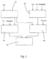
- the control unit may comprise a first module for estimating the outside temperature over a future period, a second module for estimating the energy available in the generator for the period under consideration, and a third module for learning the thermal characteristics. of the building to model its thermal behavior, a fourth module for determining the energy required for the building and a fifth module for thermal control of the generator.
- the invention also relates to a building characterized in that it comprises a thermal management system implementing the thermal management method as described above.
- the embodiment of the invention defines a thermal system for managing the energy of a building, as part of the heating of a building.
- the concept of the invention remains applicable to any thermal management of the building, for its air conditioning, ventilation, etc.
- the thermal system is a heating system, comprising a single low power generator and a control unit, comprising one or more hardware means and / or software including an microprocessor for example, implementing the thermal management method to be described later.
- the thermal system is an apparatus comprising a heat pump and having the various modules shown schematically on the figure 1 .
- the first module 10 implements a function for estimating the outside temperature over a future period P.
- the second module 20 implements a function of estimating the energy available in the generator for the period P considered.
- the third module 30 implements a learning function of the thermal characteristics of the building to model its thermal behavior.
- the fourth module 40 implements a function for determining the energy required for heating the building in the period P.
- the fifth module 50 fulfills the function of thermal management of the building, heating control.
- the thermal system comprises a man-machine interface not shown, which allows an inhabitant to enter his occupancy periods, and / or a set comfort temperature, and / or a maximum heating time value, which will be explained. thereafter.
- the concept of the invention consists in suppressing the power peaks for the heating recovery phases, for example when the occupants enter an unoccupied building, anticipating their entry by heating the building from a low power, to less partially before entry, calculated for energy optimization.
- the thermal system studies in advance the thermal situation over a future period P within the building.
- the thermal system will anticipate the situation according to a time period, that is to say hour by hour, and for a period P corresponding to the next 24 hours: alternatively, the same principle can be implemented for any other future period than 24 hours and for any time step other than the hour.
- the first module 10 of the invention therefore has the function of estimating the temperature it will do outside the building for each hour of the next 24 hours.
- any existing method can be implemented, like the one described in the document EP2146309 the invention does not relate to this module specifically.
- the outside temperature can be obtained by a first estimate of the average outside temperature T ext_moy_P over the next 24 hours, as a function of the maximum outside temperature T ext_max_P-1 and / or minimum T ext_min_P-1 measured ( s) the previous 24-hour period, and / or the outside temperature measured at the present time.
- the thermal system is equipped with an external thermometer allowing him to know at any time the measured outside temperature T ext .
- T ext_H_P T ext_min_P + T ext_max_P / 2 + T ext_min_P - T ext_max_P / 2 * sin H + not - 9 ⁇ / 12
- the module 10 therefore previously estimates the minimum average outdoor temperature values T ext_min_P and maximum T ext_max_P of the next 24 hours.
- T ext_min_P T ext_min_P - 1
- the first module 10 needs a single input data, the outside temperature past and present. The latter can be measured or estimated.
- the previous calculation could integrate or be replaced by forecast data, transmitted for example by a distant meteorological server.
- the second module 20 does not relate specifically to the preceding equations and any model for calculating the energy available at a certain time H during a next period P can be implemented.
- the input data of the module will be adapted to this other calculation model.
- the third module 30 implements a learning function of the thermal characteristics of the building to model its thermal behavior.
- E completely_H CAP ct + CAP lt ⁇ T int_cons_H - T int + GV ⁇ ⁇ 1 H [ T int + T int_cons_H - T int / 2 - T EXT_H ]
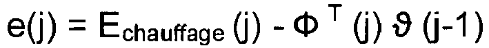
- This module 30 implements a self-adaptation of the thermal parameters of the building according to the knowledge of the real recovery phases. For this, it compares for each recovery phase the energy actually spent by the generator with that predicted by the model above and adjusts the thermal parameters if these two values differ.
- the actual heating energy can either be directly measured by an energy meter located on the heating circuit, for example, or estimated according to the operating time of the generator and a model of energy consumption such as those exhibited in the scope of the description of the second module 20.
- this module could allow a self-adaptation of any thermal model of the dwelling, is not limited to that described above.
- this self-adaptation could be developed using different methods.
- the fourth module 40 implements a function for determining the energy required for heating the building over the period P.
- E completely_H CAP ct + CAP lt ⁇ T int_cons_H - T int + GV ⁇ ⁇ 1 H T int + T int_cons_H - T int / 2 - T EXT_H
- the fifth module 50 fulfills the function of thermal management of the building, control of the heating system.
- the thermal system described above has the advantage of a great autonomy since it allows its implementation in any unknown environment. Its self-learning and its design allow it to autonomously determine and acquire all the parameters necessary for its optimal functioning. Thus, it will be advantageously as a single device, grouping in the same housing all the modules described above and the generator as such.
- a man-machine interface may make it possible to manually modify certain parameters if necessary, such as the target temperatures.
- the thermal system of the invention may not include the modules 10 and 30, these functions can be outsourced by any other system, communicating with the thermal system to transmit important parameters.
- the future outdoor temperature could be transmitted by a meteorological base, and the intrinsic thermal parameters of the building could be informed by the manufacturer of the building, or calculated by any other independent device.
- This method thus makes it possible to guarantee that the time remaining up to the hour H is sufficient for the generator to reach the set temperature at the desired time H while operating at a normal speed, without requiring any particular power.
- the invention thus makes it possible to anticipate the start-up of the generator in order to better follow the temperature setpoints. searched while operating with normal operation, without high power mode to manage the recovery phases. As a note, this anticipation can move slightly away from the rule set in step E3 'above without departing from the concept of the invention.
- the step E3 ' may more generally consist of the start-up of the generator in advance in order to respect a future temperature setpoint, taking into account the available energy E generator_H (in kJ) to the generator up to a maximum of future time H and the energy required E heating_H to reach the set temperature within the building at this time H.
- the thermal system ensures that at all times, the time required to reach a comfort set point temperature corresponding to the occupation of the building, is not greater than a predefined threshold tmax, which guarantees this inhabitant to obtain the comfort temperature in a predetermined predetermined time.
- the process of thermal management of the habitat includes a step which consists in checking that in case of start-up of the generator immediately, the time required to reach the comfort setpoint temperature does not exceed the threshold tmax.
- step E3 the generator is switched on, according to step E3 ".
- the concept of the invention is based on a step E3 of starting the generator in advance to meet a comfort guideline, whether a temperature or a duration of heating, taking into account the available energy E generator_H (in kJ) at the generator until a future time H and the energy required E heating_H to reach the setpoint within the building at this time H.
- a low temperature setpoint only the maximum time tmax defined above is sufficient to manage the thermal of the dwelling in its periods of time. vacancy. This is significantly more user friendly, economical and satisfying. However, it can also work with a low setpoint temperature, for example an anti-freeze temperature below which the system should not go down.
- the steps of the method described above will preferably be implemented for any future time H of the future period P considered. They will be particularly relevant for H hours for which the building moves from an unoccupied state to occupied, that is to say the management of recovery phases.
- the invention has been illustrated to respond to the heating of a building but it naturally appears that it could be implemented easily to manage its air conditioning.
- the first solution of the state of the art is based on a generator of 2 kW operating between two setpoint temperatures T1 and T2, for example 16 and 19 ° C.
- T1 and T2 At time t1, which must correspond to the building occupancy time, the temperature setpoint changes from T1 to T2.
- the generator starts at this moment t1 and reaches the setpoint temperature T2 according to the slope 11.
- the second solution of the state of the art is based on a basic generator of 2 kW and a complementary generator of 6kW. At time t1, it reaches the setpoint according to the slope 12, much faster as the high-power generator is used for this recovery phase.
- the thermal system according to the invention in fact determines the instant t0 preceding the instant t1, for which the generator must be started, to reach the setpoint temperature T2 at time t1, along a slope 13 parallel to that of the first solution. Thanks to this solution, the comfort of the user is satisfied, without resorting to high heating power.
- the figure 3 represents the behavior of the two state of the art solutions in a long absence scenario. Such a scenario differs from the previous one in that the lower indoor temperature can be allowed to go down for more savings. However, this complicates the recovery phase.
- the control is done around the low set point temperature T1 at 12 ° C.
- the occupant returns home and raises the temperature setpoint to the T2 value of 19 ° C.
- the first solution reaches the high setpoint according to the slope 21, in about 12H, slower than the slope 22 of the second solution, which reaches the setpoint at 4H, despite its high power which is no longer satisfactory in such a scenario.
- the curve 27 illustrates the variation of outside temperature during this period.
- the figure 4 illustrates the same scenario with the thermal system of the invention.
- the internal temperature 24 is not regulated around the low setpoint T1 but around a setpoint represented by the curve 25, calculated automatically by the system, which thus varies with time, since depends in particular on the outside temperature, and is about 2 ° C above T1.
- the thermal system has therefore automatically determined the heating required during the absence to reach the 6H heating back, without knowing the moment of return, which meets the desire for comfort of the occupant, for a minimum cost.
Description
L'invention concerne un procédé de gestion thermique d'un bâtiment ainsi qu'un système thermique mettant en oeuvre un tel procédé. Elle porte aussi sur un support comprenant un logiciel mettant en oeuvre un tel procédé. Enfin, elle concerne aussi un bâtiment équipé d'un tel système thermique.The invention relates to a thermal management method of a building and a thermal system implementing such a method. It also relates to a medium comprising software implementing such a method. Finally, it also relates to a building equipped with such a thermal system.
Lors de phases d'inoccupation des bâtiments, leur température est souvent réduite pour économiser l'énergie. Pour cela, le chauffage est par exemple stoppé une certaine période, jusqu'à atteindre une température intérieure correspondant à une température de consigne basse. Puis, lors du retour des occupants, la température de confort maximale est de nouveau recherchée. Une phase dite de relance est mise en route, qui consiste à chauffer de nouveau le bâtiment pour repasser de la température intérieure basse à la température intérieure haute.During periods of vacancy of buildings, their temperature is often reduced to save energy. For this, the heating is for example stopped for a certain period until reaching an indoor temperature corresponding to a low setpoint temperature. Then, when the occupants return, the maximum comfort temperature is again sought. A so-called recovery phase is started, which consists in heating the building again to go from low indoor temperature to high indoor temperature.
Une première solution de l'état de la technique repose sur un générateur d'énergie fonctionnant selon un mode de régulation de la température entre deux consignes de température haute et basse, la température de consigne haute étant utilisée aux horaires pour lesquels les occupants sont présents alors que la température de consigne basse est utilisée lorsqu'ils sont absents. Cette solution permet une économie d'énergie par rapport à une solution dans laquelle la température de confort maximal serait toujours recherchée mais reste très simpliste et non optimisée. De plus, la température de consigne basse est souvent renseignée de manière aléatoire par les occupants eux-mêmes, ou prédéfinie en usine sans tenir compte du climat réel. Ainsi, lorsque les occupants rentrent, il se peut que le temps de chauffage soit très long pour atteindre la température de confort, si la température a été trop réduite. Dans un tel cas, la phase de relance paraît interminable. Inversement, il se peut que la température de consigne basse ait été choisie trop élevée et ait entraîné une consommation énergétique inutile en l'absence de ses occupants. De plus, un occupant aura tendance à renseigner des températures de consigne ne correspondant pas à ses vrais horaires pour tenter d'anticiper une éventuelle défaillance, ou s'il a entendu des prévisions météorologiques de basse température. Ainsi, il apparaît bien que l'optimisation d'un tel système est très difficile. En pratique, il en résulte une insatisfaction des occupants qui n'ont pas toujours leur température de confort dans des délais acceptables et une consommation énergétique élevée et non optimisée.
Une seconde solution de l'état de la technique repose sur des systèmes de chauffage se présentant comme des appareils multifonctions qui intègrent en fait deux générateurs complémentaires : un générateur de base de faible puissance, par exemple entre 1,5 à 6 kW, utilisé pour les besoins énergétiques en régimes permanents et particulièrement adapté aux bâtiments très isolés, dits à basse consommation énergétique, qui sont en plein développement, et un générateur d'appoint de forte puissance, pouvant aller jusqu'à quatre fois la puissance de base, par exemple entre 6 et 9 kW, utilisé pour les courts régimes transitoires. Cette seconde solution fonctionne toujours selon une régulation de la température à partir d'une température de confort et une température basse pour les phases d'inoccupation. Grâce au générateur de forte puissance, utilisé exclusivement pour les phases de relance, la température de confort est atteinte en général dans un temps satisfaisant. Cette solution présente le premier inconvénient d'exiger un coût d'investissement élevé pour équiper un bâtiment. Elle présente de plus un second inconvénient d'entraîner des périodes de pics de consommation énergétique élevés, ce qui complique la gestion énergétique globale d'un territoire, tout en exigeant des abonnements de chaque individu à un réseau électrique adaptés à leurs besoins ponctuels de forte puissance, ce qui présente généralement un coût important pour de courtes périodes d'utilisation. Enfin, elle présente toujours le même inconvénient de mise au point que la première solution de l'état de la technique, notamment pour le choix de la valeur de la température de consigne d'absence.A second solution of the state of the art is based on heating systems that are multifunctional devices that actually integrate two complementary generators: a low power base generator, for example between 1.5 to 6 kW, used to energy needs in steady-state and particularly adapted to very isolated, so-called low energy consumption buildings, which are in full development, and a high power booster generator, up to four times the base power, for example between 6 and 9 kW, used for short transient conditions. This second solution always works according to a regulation of the temperature starting from a temperature of comfort and a low temperature for the phases of unoccupation. Thanks to the high power generator, used exclusively for the recovery phases, the comfort temperature is generally reached in a satisfactory time. This solution has the first disadvantage of requiring a high investment cost to equip a building. It also has a second disadvantage of causing periods of high energy consumption peaks, which complicates the overall energy management of a customer. territory, while requiring subscriptions of each individual to an electricity network adapted to their specific needs of high power, which generally presents a significant cost for short periods of use. Finally, it always has the same disadvantage of focusing as the first solution of the state of the art, especially for the choice of the value of the absence setpoint temperature.
Ainsi, un objet général de l'invention est de proposer une solution améliorée de gestion thermique d'un bâtiment, qui résout tout ou partie des inconvénients précédents.Thus, a general object of the invention is to propose an improved thermal management solution for a building, which solves all or some of the foregoing disadvantages.
A cet effet, l'invention repose sur un procédé de gestion thermique d'un bâtiment, à partir d'un système thermique équipé d'un générateur à faible puissance, caractérisé en ce qu'il comprend une étape (E3) de mise en route du générateur de manière anticipée en l'absence d'occupant dans le bâtiment afin de respecter une consigne de confort future à un instant futur (H), en tenant compte de l'énergie disponible (Egénérateur_H) au générateur jusqu'à cet instant futur (H) et de l'énergie nécessaire (Echauffage_H) pour atteindre la consigne de confort future au sein du bâtiment à cet instant futur (H).For this purpose, the invention is based on a method of thermal management of a building, from a thermal system equipped with a low power generator, characterized in that it comprises a step (E3) of implementation. generator route in advance in the absence of occupant in the building in order to meet a set of future comfort at a future time (H), taking into account the available energy (E generator_H ) generator until this future instant (H) and the energy required (E heating_H ) to reach the future comfort setpoint within the building at this future instant (H).
La consigne de confort future peut être une consigne de température et le procédé peut comprendre les étapes suivantes :
- (E1) - Calcul de l'énergie disponible (Egénérateur_H) au générateur jusqu'à l'instant futur (H) ;
- (E2) - Calcul de l'énergie nécessaire (Echauffage_H) pour atteindre la température de consigne au sein du bâtiment à cet instant (H) ;
- (E3') - Comparaison des deux valeurs précédentes et mise en route du générateur si Egénérateur_H < Echauffage_H.
- (E1) - Calculation of the available energy (E generator_H ) to the generator until the future moment (H);
- (E2) - Calculation of the energy required (E heating_H ) to reach the set temperature within the building at this time (H);
- (E3 ') - Comparison of the two previous values and start of the generator if E generator_H <E heater_H .
La consigne de confort future peut être une durée maximale (tmax) autorisée pour atteindre une température de confort en cas de nécessité à l'instant futur (H).The future comfort setpoint may be a maximum duration (tmax) allowed to reach a comfort temperature if necessary at the future time (H).
Le procédé peut comprendre les étapes suivantes :
- (E1) - Calcul de l'énergie disponible (Egénérateur_H) au générateur jusqu'à l'instant futur (H) ;
- (E2) - Calcul de l'énergie nécessaire (Echauffage_H) pour atteindre la température de consigne au sein du bâtiment à cet instant (H) ;
- (E3") - Comparaison des deux valeurs précédentes et mise en route du générateur si H > tmax.
- (E1) - Calculation of the available energy (E generator_H ) to the generator until the future moment (H);
- (E2) - Calculation of the energy required (E heating_H ) to reach the set temperature within the building at this time (H);
- (E3 ") - Comparison of the two previous values and start of the generator if H> tmax.
Le procédé de gestion thermique d'un bâtiment peut comprendre une étape de calcul d'une température de consigne basse pour réguler le fonctionnement du générateur en l'absence d'occupant dans le bâtiment, cette consigne basse étant variable avec le temps.The thermal management method of a building may comprise a step of calculating a low setpoint temperature to regulate the operation of the generator in the absence of occupant in the building, this low setpoint being variable with time.
Le procédé de gestion thermique d'un bâtiment peut comprendre une étape de saisie d'au moins une des données suivantes :
- Saisie d'au moins une consigne de température en cas d'occupation du bâtiment et/ou en cas de non-occupation ; et/ou
- Saisie des périodes d'occupation et/ou de non-occupation du bâtiment ; et/ou
- Saisie d'une durée maximale (tmax) autorisée de fonctionnement du générateur pour atteindre une certaine température de confort dans le bâtiment.
- Entering at least one temperature setpoint in the event of occupation of the building and / or in case of non-occupancy; and or
- Entering periods of occupation and / or non-occupation of the building; and or
- Entering a maximum allowed duration (tmax) for the generator to reach a certain comfort temperature in the building.
Le procédé peut comprendre une étape d'évaluation de la température extérieure future sur plusieurs instants (H) d'une période future (P).The method may include a step of evaluating the future outdoor temperature over several times (H) of a future period (P).
Le procédé peut comprendre une étape d'auto-apprentissage des caractéristiques thermiques du bâtiment.The method may include a step of self-learning the thermal characteristics of the building.
Le procédé de gestion thermique d'un bâtiment peut comprendre le calcul de l'énergie disponible (Egénérateur_H) au générateur jusqu'à l'instant futur (H) par l'équation suivante : 

Avec :
- a, b, c, d : paramètres caractéristiques d'une pompe à chaleur ;
- Te_evap : température d'entrée à l'évaporateur de la pompe à chaleur ;
- Te_cond : température d'entrée au condenseur de la pompe à chaleur.
- a, b, c, d: characteristic parameters of a heat pump;
- T e_evap : inlet temperature to the evaporator of the heat pump;
- T e_cond : inlet temperature to the condenser of the heat pump.
Le procédé de gestion thermique d'un bâtiment peut comprendre le calcul de l'énergie nécessaire (Echauffage_H) pour atteindre une température intérieure de consigne du bâtiment à l'instant (H) par l'équation suivante : 
Avec:
- Tint : température intérieure à l'instant présent ;
- Tint_cons_H : température intérieure de consigne à l'instant H ;
- Text_H : température extérieure estimée à l'instant H ;
- CAPct : capacité calorifique court terme du bâtiment ;
- CAPIt : capacité calorifique long terme du bâtiment ;
- GV : coefficient de déperditions thermiques du bâtiment.
- T int : internal temperature at the present moment;
- T int_cons_H : set internal temperature at time H;
- T ext_H : external temperature estimated at time H;
- CAP ct : short-term heat capacity of the building;
- CAP It : long-term heat capacity of the building;
- GV: coefficient of thermal losses of the building.
Le procédé de gestion thermique d'un bâtiment peut comprendre la répétition pour plusieurs instants (H) d'une période future (P) d'une étape d'estimation du besoin de mise en route du générateur de manière anticipée en l'absence d'occupant dans le bâtiment afin de respecter une consigne de confort future à un instant futur (H), en tenant compte de l'énergie disponible (Egénérateur_H) au générateur jusqu'à cet instant futur (H) et de l'énergie nécessaire (Echauffage_H) pour atteindre la consigne de confort future au sein du bâtiment à cet instant futur (H).The thermal management method of a building may include the repetition for several instants (H) of a future period (P) of a step of estimating the need to start the generator in advance in the absence of occupying the building in order to respect a future comfort regulation at a future time (H), taking into account the available energy (E generator_H ) to the generator until this future moment (H) and the necessary energy (E heating_H ) to reach the setpoint of future comfort within the building at this future moment (H).
L'invention porte aussi sur un support informatique comprenant un programme informatique mettant en oeuvre les étapes du procédé de gestion thermique d'un bâtiment tel que décrit précédemment.The invention also relates to a computer medium comprising a computer program implementing the steps of the thermal management method of a building as described above.
L'invention porte aussi sur un système de gestion thermique d'un bâtiment comprenant un générateur à faible puissance, caractérisé en ce qu'il comprend une unité de contrôle qui met en oeuvre le procédé de gestion thermique d'un bâtiment tel que décrit précédemment.The invention also relates to a thermal management system of a building comprising a low power generator, characterized in that it comprises a control unit which implements the thermal management method of a building as described above. .
L'unité de contrôle peut comprendre un premier module d'estimation de la température extérieure sur une période future, un second module d'estimation de l'énergie disponible dans le générateur pour la période considérée, un troisième module d'apprentissage des caractéristiques thermiques du bâtiment pour modéliser son comportement thermique, un quatrième module de détermination de l'énergie nécessaire pour le bâtiment et un cinquième module de pilotage thermique du générateur.The control unit may comprise a first module for estimating the outside temperature over a future period, a second module for estimating the energy available in the generator for the period under consideration, and a third module for learning the thermal characteristics. of the building to model its thermal behavior, a fourth module for determining the energy required for the building and a fifth module for thermal control of the generator.
L'invention porte aussi sur un bâtiment caractérisé en ce qu'il comprend un système de gestion thermique mettant en oeuvre le procédé de gestion thermique tel que décrit précédemment.The invention also relates to a building characterized in that it comprises a thermal management system implementing the thermal management method as described above.
Ces objets, caractéristiques et avantages de la présente invention seront exposés en détail dans la description suivante d'un mode d'exécution particulier fait à titre non-limitatif en relation avec les figures jointes parmi lesquelles :
- La
figure 1 illustre schématiquement un système thermique pour un bâtiment selon un mode d'exécution de l'invention. - La
figure 2 représente l'évolution comparative de températures intérieures d'un bâtiment avec ou sans le mode d'exécution de l'invention selon un premier scénario. - Les
figures 3 et 4 représentent l'évolution comparative de températures intérieures d'un bâtiment avec ou sans le mode d'exécution de l'invention selon un second scénario.
- The
figure 1 schematically illustrates a thermal system for a building according to an embodiment of the invention. - The
figure 2 represents the comparative evolution of interior temperatures of a building with or without the embodiment of the invention according to a first scenario. - The
Figures 3 and 4 represent the comparative evolution of interior temperatures of a building with or without the embodiment of the invention according to a second scenario.
Le mode d'exécution de l'invention définit un système thermique de gestion de l'énergie d'un bâtiment, dans le cadre du chauffage d'un bâtiment. Toutefois, le concept de l'invention reste applicable à toute gestion thermique du bâtiment, pour sa climatisation, sa ventilation, etc.The embodiment of the invention defines a thermal system for managing the energy of a building, as part of the heating of a building. However, the concept of the invention remains applicable to any thermal management of the building, for its air conditioning, ventilation, etc.
Le système thermique selon le mode d'exécution de l'invention se présente comme un système de chauffage, comprenant un générateur unique de faible puissance et une unité de contrôle, comprenant un ou plusieurs moyens matériels (hardware) et/ou logiciels (software) dont un microprocesseur par exemple, mettant en oeuvre le procédé de gestion thermique qui sera décrit ultérieurement.The thermal system according to the embodiment of the invention is a heating system, comprising a single low power generator and a control unit, comprising one or more hardware means and / or software including an microprocessor for example, implementing the thermal management method to be described later.
Le système thermique selon le mode d'exécution de l'invention se présente comme un appareil comprenant une pompe à chaleur et présentant les différents modules représentés schématiquement sur la
Le concept de l'invention consiste à supprimer les pics de puissance pour les phases de relance du chauffage, par exemple lorsque les occupants entrent dans un bâtiment non occupé, en anticipant leur entrée en chauffant le bâtiment à partir d'une faible puissance, au moins partiellement avant leur entrée, de manière calculée pour une optimisation énergétique. Pour cela, le système thermique étudie à l'avance la situation thermique sur une période future P au sein du bâtiment.The concept of the invention consists in suppressing the power peaks for the heating recovery phases, for example when the occupants enter an unoccupied building, anticipating their entry by heating the building from a low power, to less partially before entry, calculated for energy optimization. For this, the thermal system studies in advance the thermal situation over a future period P within the building.
Ce concept va maintenant être détaillé en décrivant plus précisément les différents modules du système thermique selon le mode d'exécution de l'invention. A titre d'exemple, le système thermique va anticiper la situation selon une période horaire, c'est-à-dire heure par heure, et pour une période P correspondant aux 24 prochaines heures : en variante, le même principe pourra être implémenté pour toute autre période future que 24 heures et pour tout pas temporel autre que l'heure.This concept will now be detailed by describing more precisely the various modules of the thermal system according to the embodiment of the invention. For example, the thermal system will anticipate the situation according to a time period, that is to say hour by hour, and for a period P corresponding to the next 24 hours: alternatively, the same principle can be implemented for any other future period than 24 hours and for any time step other than the hour.
Le premier module 10 de l'invention a donc pour fonction d'estimer la température qu'il fera à l'extérieur du bâtiment pour chaque heure des prochaines 24 heures. Pour cela, toute méthode existante peut être implémentée, comme celle décrite dans le document
A titre d'exemple, la température extérieure peut être obtenue par une première estimation de la température extérieure moyenne Text_moy_P sur les prochaines 24 heures, en fonction de la température extérieure maximale Text_max_P-1 et/ou minimale Text_min_P-1 mesurée(s) de la période de 24 heures précédente, et/ou de la température extérieure mesurée à l'instant présent. Pour cela, le système thermique est équipé d'un thermomètre extérieur lui permettant de connaître à tout instant la température extérieure mesurée Text.By way of example, the outside temperature can be obtained by a first estimate of the average outside temperature T ext_moy_P over the next 24 hours, as a function of the maximum outside temperature T ext_max_P-1 and / or minimum T ext_min_P-1 measured ( s) the previous 24-hour period, and / or the outside temperature measured at the present time. For this, the thermal system is equipped with an external thermometer allowing him to know at any time the measured outside temperature T ext .
La température extérieure moyenne sur les prochaines 24 heures peut dépendre de l'heure du calcul et être définie par les formules suivantes : ![]()
![]()
![]()
![]()
![]()
![]()
![]()
![]()
Ensuite, à partir de la température extérieure moyenne estimée de la période P, le profil horaire de la température extérieure de cette période P est estimé par la fonction sinus suivante : ![]()
![]()
Avec :
- Text_H_P : température extérieure estimée à l'heure H de la période P,
- Text_min_P : température extérieure minimale des 24 prochaines heures,
- Text_max_P : température extérieure maximale des 24 prochaines heures,
- n : heure réelle de la journée.
- T ext_H_P : estimated outside temperature at time H of period P,
- T ext_min_P : minimum outside temperature of the next 24 hours,
- T ext_max_P : maximum outside temperature of the next 24 hours,
- n: real time of the day.
Pour appliquer cette fonction, le module 10 estime donc auparavant les valeurs de température extérieure moyenne minimale Text_min_P et maximale Text_max_P des prochaines 24 heures.To apply this function, the
Pour cela, les formules suivantes peuvent être utilisées : ![]()
![]()
![]()
![]()
![]()
![]()
![]()
![]()
Suite à la description précédente, il apparaît donc que le premier module 10 a besoin d'une seule donnée en entrée, la température extérieure passée et présente. Cette dernière peut être mesurée ou estimée.Following the above description, it therefore appears that the
En variante, le calcul précédent pourrait intégrer ou être remplacé par des données prévisionnelles, transmises par exemple par un serveur distant météorologique.Alternatively, the previous calculation could integrate or be replaced by forecast data, transmitted for example by a distant meteorological server.
Le second module 20 met en oeuvre une fonction d'estimation de l'énergie disponible dans le générateur pour la période P considérée. Pour cela, le calcul le plus simple consiste à considérer la puissance nominale Pnominal (en kJ/h) du générateur pour en déduire l'énergie disponible par la formule suivante : 
Avec:
- Egénérateur_H : énergie disponible (en kJ) au générateur jusqu'à l'heure H ;
- H : l'heure parmi les 24 prochaines heures pour laquelle l'énergie disponible au générateur est estimée.
- E generator_H : available energy (in kJ) at the generator until time H;
- H: the hour within the next 24 hours for which the energy available at the generator is estimated.
Naturellement, ce calcul est adapté au type de générateur utilisé. La formule précédente est bien adaptée à un chauffage à base de résistance électrique. Toutefois, si le générateur est une pompe à chaleur air extrait/air neuf, l'énergie disponible peut se calculer par l'équation suivante : 
Avec :
- a, b, c, d : paramètres caractéristiques de la pompe à chaleur ;
- Te_evap : température d'entrée à l'évaporateur de la pompe à chaleur ;
- Te_cond : température d'entrée au condenseur de la pompe à chaleur ;
- H : l'heure parmi les 24 prochaines heures pour laquelle l'énergie disponible au générateur est estimée.
- a, b, c, d: characteristic parameters of the heat pump;
- T e_evap : inlet temperature to the evaporator of the heat pump;
- T e_cond : inlet temperature to the condenser of the heat pump;
- H: the hour within the next 24 hours for which the energy available at the generator is estimated.
Dans le cas d'une pompe à chaleur air/air, tel qu'illustré sur la ![]()
![]()
![]()
![]()
Naturellement, le second module 20 ne porte pas spécifiquement sur les équations précédentes et tout modèle de calcul de l'énergie disponible à une certaine heure H au cours d'une prochaine période P peut être mis en oeuvre. Dans ce cas, les données d'entrée du module seront adaptées à cet autre modèle de calcul.Naturally, the
Le troisième module 30 met en oeuvre une fonction d'apprentissage des caractéristiques thermiques du bâtiment pour modéliser son comportement thermique.The
Pour cela, le mode d'exécution de l'invention considère le modèle thermique représenté par l'équation suivante : 
Avec :
- Echauffage_H : énergie de chauffage nécessaire jusqu'à l'heure H (en kJ) ;
- Tint : température intérieure à l'instant présent (en K) ;
- Tint_cons_H : température intérieure de consigne à l'heure H (en K) ;
- Text_H : température extérieure estimée à l'heure H ;
- CAPct : capacité calorifique court terme du bâtiment (représentant en fait le mobilier principalement) (en kJ/K) ;
- CAPIt : capacité calorifique long terme du bâtiment (représentant en fait les murs principalement) (en kJ/K) ;
- GV : coefficient de déperditions thermiques du bâtiment (en kJ/(h.K)) ;
- H : l'heure parmi les 24 prochaines heures pour laquelle l'énergie disponible au générateur est estimée.
- E heating_H : heating energy required up to time H (in kJ);
- T int : internal temperature at the present moment (in K);
- T int_cons_H : set room temperature at time H (in K);
- T ext_H : estimated outside temperature at time H;
- CAP ct : short-term heating capacity of the building (mainly representing furniture mainly) (in kJ / K);
- CAP It : long-term heat capacity of the building (basically representing the walls mainly) (in kJ / K);
- GV: heat loss coefficient of the building (in kJ / (hK));
- H: the hour within the next 24 hours for which the energy available at the generator is estimated.
Cette équation peut s'écrire de manière matricielle par : ![]()
![]()
Avec ϑ = [CAPct CAPIt GV] ![]()
![]()
Ce module 30 met en oeuvre une auto-adaptation des paramètres thermiques du bâtiment en fonction de la connaissance des phases réelles de relance. Pour cela, il compare pour chaque phase de relance l'énergie réellement dépensée par le générateur avec celle prédite par le modèle ci-dessus et ajuste les paramètres thermiques si ces deux valeurs diffèrent.This
L'énergie de chauffage réelle peut soit être directement mesurée par un compteur d'énergie situé sur le circuit de chauffage par exemple, ou être estimée en fonction du temps de fonctionnement du générateur et un modèle de consommation d'énergie tel que ceux exposés dans le cadre de la description du second module 20.The actual heating energy can either be directly measured by an energy meter located on the heating circuit, for example, or estimated according to the operating time of the generator and a model of energy consumption such as those exhibited in the scope of the description of the
L'auto-adaptation des paramètres thermiques CAPct, CAPIt, et GV, peut être basée sur l'algorithme suivant : ![]()
![]()
Les matrices e et K représentent respectivement l'erreur a priori entre le besoin de chauffage mesuré et le besoin de chauffage estimé, et le gain d'adaptation à appliquer pour tenir compte de cette erreur. Ces deux matrices se calculent de la façon suivante :
- L'erreur a priori :
- Gain d'adaptation :

- The error a priori:
- Gain of adaptation:
La matrice P est réactualisée de la manière suivante : ![]()
![]()
Où le coefficient λ est un facteur d'oubli et le coefficient µ un facteur de pondération.Where the coefficient λ is a forgetting factor and the coefficient μ is a weighting factor.
Naturellement, ce module pourrait permettre une auto-adaptation de tout modèle thermique de l'habitât, n'est pas limité à celui décrit ci-dessus. De plus, cette auto-adaptation pourrait être mise au point selon différentes méthodes.Naturally, this module could allow a self-adaptation of any thermal model of the dwelling, is not limited to that described above. In addition, this self-adaptation could be developed using different methods.
Le quatrième module 40 met en oeuvre une fonction de détermination de l'énergie nécessaire pour le chauffage du bâtiment sur la période P.The
Il comprend donc en entrée les paramètres suivants :
- Le modèle thermique défini par le troisième module décrit ci-dessus;
- Une estimation de la température extérieure pour la période P, fournie par le premier module ;
- Un profil de température intérieure de consigne.
- The thermal model defined by the third module described above;
- An estimate of the outside temperature for the period P, provided by the first module;
- A set indoor temperature profile.
Il met en oeuvre le modèle thermique du bâtiment, mis au point par le module décrit précédemment, pour obtenir l'énergie nécessaire pour atteindre la température de consigne à une heure H de la période P par la formule : 
Le cinquième module 50 remplit la fonction de gestion thermique du bâtiment, de pilotage du système de chauffage.The
Notamment, il compare les résultats des deuxième et quatrième modules 20, 40 dans le but d'anticiper la mise en route du générateur de manière appropriée pour obtenir la température de consigne à toute heure H, tout en utilisant une puissance de chauffage réduite. Cette anticipation est particulièrement pertinente pour gérer les changements d'occupation du bâtiment, correspondant aux phases de relance explicitées précédemment.In particular, it compares the results of the second and
Le système thermique décrit ci-dessus présente l'avantage d'une grande autonomie puisqu'il permet son implémentation dans tout environnement inconnu. Son auto-apprentissage et sa conception lui permettent de déterminer de manière autonome et d'acquérir tous les paramètres nécessaires à son fonctionnement optimal. Ainsi, il se présentera avantageusement comme un appareil unique, regroupant dans un même boîtier tous les modules décrits ci-dessus et le générateur en tant que tel. Eventuellement, une interface homme machine peut permettre de modifier manuellement certains paramètres si nécessaires, comme les températures de consigne.The thermal system described above has the advantage of a great autonomy since it allows its implementation in any unknown environment. Its self-learning and its design allow it to autonomously determine and acquire all the parameters necessary for its optimal functioning. Thus, it will be advantageously as a single device, grouping in the same housing all the modules described above and the generator as such. Optionally, a man-machine interface may make it possible to manually modify certain parameters if necessary, such as the target temperatures.
Lors de sa première mise en route, il comprend des paramètres d'initialisation qui peuvent être des valeurs moyennes, renseignées en usine, sans besoin de grande précision.When it is first started, it includes initialization parameters that can be average values, given in the factory, without the need for high precision.
En variante toutefois, le système thermique de l'invention pourrait ne pas comprendre les modules 10 et 30, ces fonctions pouvant être externalisées par tout autre système, communiquant avec le système thermique pour lui transmettre les paramètres importants. Ainsi, comme nous l'avons vu, la température extérieure future pourrait être transmise par une base météorologique, et les paramètres thermiques intrinsèques du bâtiment pourraient être renseignés par le fabricant du bâtiment, ou calculés par tout autre dispositif indépendant.Alternatively, however, the thermal system of the invention may not include the
Ainsi, le système thermique de l'invention met en oeuvre le procédé de gestion de l'énergie thermique de l'habitat comprenant les étapes E1, E2, E3' suivantes :
- E1 - Calcul de l'énergie disponible Egénérateur_H (en kJ) au générateur jusqu'à une heure future H ;
- E2 - Calcul de l'énergie nécessaire Echauffage_H pour atteindre la température de consigne au sein du bâtiment à cette heure H ;
- E3' - Comparaison des deux valeurs précédentes et mise en route du générateur dès que Egénérateur_H < Echauffage_H.
- E1 - Calculation of the available energy E generator_H (in kJ) to the generator until a future time H;
- E2 - Calculation of the energy required E heating_H to reach the set temperature within the building at this time H;
- E3 '- Comparison of the two previous values and start of the generator as soon as E generator_H <E heater_H .
Ce procédé permet ainsi de garantir que le temps restant jusqu'à l'heure H est suffisant pour que le générateur atteigne la température de consigne à l'heure H souhaitée en fonctionnant à un régime normal, sans exiger une puissance particulière.This method thus makes it possible to guarantee that the time remaining up to the hour H is sufficient for the generator to reach the set temperature at the desired time H while operating at a normal speed, without requiring any particular power.
En remarque, l'invention permet donc d'anticiper la mise en route du générateur pour suivre au mieux les consignes de température recherchées tout en fonctionnant avec un fonctionnement normal, sans mode à forte puissance pour gérer les phases de relance. En remarque, cette anticipation peut s'éloigner légèrement de la règle fixée à l'étape E3' ci-dessus sans sortir du concept de l'invention.As a remark, the invention thus makes it possible to anticipate the start-up of the generator in order to better follow the temperature setpoints. searched while operating with normal operation, without high power mode to manage the recovery phases. As a note, this anticipation can move slightly away from the rule set in step E3 'above without departing from the concept of the invention.
Ainsi, l'étape E3' peut plus généralement consister en la mise en route du générateur de manière anticipée afin de respecter une consigne de température future, en tenant compte de l'énergie disponible Egénérateur_H (en kJ) au générateur jusqu'à une heure future H et de l'énergie nécessaire Echauffage_H pour atteindre la température de consigne au sein du bâtiment à cette heure H.Thus, the step E3 'may more generally consist of the start-up of the generator in advance in order to respect a future temperature setpoint, taking into account the available energy E generator_H (in kJ) to the generator up to a maximum of future time H and the energy required E heating_H to reach the set temperature within the building at this time H.
Le procédé précédent fonctionne bien pour gérer les relances programmées, à partir de températures de consigne définies à l'avance. Toutefois, il peut arriver certaines situations imprévues dans lesquelles un habitant rentre dans son habitation plus tôt que prévu, ou à un instant indéterminé. Dans un tel cas, il n'a aucun moyen d'accélération du chauffage de son habitation puisque ce chauffage dépend uniquement de la puissance limitée de son unique générateur.The above method works well to manage the programmed restarts, from preset setpoint temperatures. However, there may be some unforeseen situations in which an inhabitant returns to their home earlier than expected, or at an indefinite time. In such a case, he has no means of accel- erating the heating of his home since this heating depends solely on the limited power of his single generator.
Pour répondre à un minimum de confort pour faire face à ces situations, le système thermique fait en sorte qu'à tout instant, le temps nécessaire pour atteindre une température de consigne de confort correspondant à l'occupation du bâtiment, ne soit pas supérieur à un seuil tmax prédéfini, ce qui garantit à cet habitant d'obtenir la température de confort dans un temps prédéterminé raisonnable.To meet a minimum of comfort to cope with these situations, the thermal system ensures that at all times, the time required to reach a comfort set point temperature corresponding to the occupation of the building, is not greater than a predefined threshold tmax, which guarantees this inhabitant to obtain the comfort temperature in a predetermined predetermined time.
Pour cela, le procédé de gestion thermique de l'habitat comprend une étape qui consiste à vérifier qu'en cas de mise en route du générateur immédiatement, le temps nécessaire pour atteindre la température de consigne de confort ne dépasse pas le seuil tmax.For this, the process of thermal management of the habitat includes a step which consists in checking that in case of start-up of the generator immediately, the time required to reach the comfort setpoint temperature does not exceed the threshold tmax.
Ainsi, même si l'étape E3' vérifie que Egénérateur_H > Echauffage_H, si H > tmax alors le générateur est mis en route, selon une étape E3".Thus, even if step E3 'checks that E générateur_H> E chauffage_H if H> tmax then the generator is switched on, according to step E3 ".
Ainsi finalement, le concept de l'invention repose sur une étape E3 de mise en route du générateur de manière anticipée afin de respecter une consigne de confort, que ce soit une température ou une durée de chauffe, en tenant compte de l'énergie disponible Egénérateur_H (en kJ) au générateur jusqu'à une heure future H et de l'énergie nécessaire Echauffage_H pour atteindre la consigne au sein du bâtiment à cette heure H.Thus finally, the concept of the invention is based on a step E3 of starting the generator in advance to meet a comfort guideline, whether a temperature or a duration of heating, taking into account the available energy E generator_H (in kJ) at the generator until a future time H and the energy required E heating_H to reach the setpoint within the building at this time H.
En remarque, avec une telle approche, l'occupant n'a plus besoin d'indiquer au système thermique une consigne de température basse : seul le temps maximal tmax défini ci-dessus suffit pour gérer la thermique de l'habitât dans ses périodes d'inoccupation. Cela est nettement plus convivial, économique et satisfaisant. Toutefois, il peut de plus fonctionner aussi avec une température de consigne basse, par exemple une température de hors-gel en dessous de laquelle le système ne doit pas descendre.Note, with such an approach, the occupant no longer needs to indicate the thermal system a low temperature setpoint: only the maximum time tmax defined above is sufficient to manage the thermal of the dwelling in its periods of time. vacancy. This is significantly more user friendly, economical and satisfying. However, it can also work with a low setpoint temperature, for example an anti-freeze temperature below which the system should not go down.
Le procédé de gestion thermique de l'habitat comprend une étape préalable de saisie de tout ou partie des données suivantes, par un occupant ou un constructeur :
- Saisie d'au moins une température de confort en cas d'occupation du bâtiment ;
- Saisie des périodes d'occupation et/ou d'absence du bâtiment ;
- Saisie d'une durée maximale tmax autorisée de chauffage du bâtiment.
- Entering at least one comfort temperature when occupying the building;
- Entering periods of occupation and / or absence of the building;
- Entering a maximum duration tmax allowed for heating the building.
Les étapes du procédé décrit précédemment seront de préférence mises en oeuvre pour toute heure H future de la période P future considérée. Elles seront particulièrement pertinentes pour les heures H pour lesquelles le bâtiment passe d'un état inoccupé à occupé, c'est-à-dire la gestion des phases de relance.The steps of the method described above will preferably be implemented for any future time H of the future period P considered. They will be particularly relevant for H hours for which the building moves from an unoccupied state to occupied, that is to say the management of recovery phases.
De plus, l'invention a été illustrée pour répondre au chauffage d'un bâtiment mais il apparaît naturellement qu'elle pourrait être implémentée facilement pour gérer sa climatisation.In addition, the invention has been illustrated to respond to the heating of a building but it naturally appears that it could be implemented easily to manage its air conditioning.
Ainsi, la solution retenue répond bien aux objets de l'invention et présente les avantages suivants :
- Elle limite les pics de puissance en évitant le recours à un générateur complémentaire à forte puissance ;
- Elle satisfait le confort thermique des habitants tout en économisant des coûts ;
- Elle permet d'utiliser des générateurs à faible puissance, qui sont suffisants pour les bâtiments bien isolés.
- It limits power peaks by avoiding the use of a high-power complementary generator;
- It satisfies the thermal comfort of the inhabitants while saving costs;
- It allows the use of low power generators, which are sufficient for well insulated buildings.
Les
La première solution de l'état de la technique repose sur un générateur de 2 kW fonctionnant entre deux températures de consigne T1 et T2, par exemple 16 et 19 °C. A l'instant t1, qui doit correspondre à l'heure d'occupation du bâtiment, la consigne de température passe de T1 à T2. Le générateur se met en route à cet instant t1 et atteint la température de consigne T2 selon la pente 11.The first solution of the state of the art is based on a generator of 2 kW operating between two setpoint temperatures T1 and T2, for example 16 and 19 ° C. At time t1, which must correspond to the building occupancy time, the temperature setpoint changes from T1 to T2. The generator starts at this moment t1 and reaches the setpoint temperature T2 according to the
La seconde solution de l'état de la technique repose sur un générateur de base de 2 kW et un générateur complémentaire de 6kW. A l'instant t1, il atteint la valeur de consigne selon la pente 12, beaucoup plus rapidement puisque le générateur à forte puissance est utilisé pour cette phase de relance.The second solution of the state of the art is based on a basic generator of 2 kW and a complementary generator of 6kW. At time t1, it reaches the setpoint according to the
Le système thermique selon l'invention détermine en fait l'instant t0 précédent l'instant t1, pour lequel il faut mettre en route le générateur, pour atteindre la température de consigne T2 à l'instant t1, selon une pente 13 parallèle à celle de la première solution. Grâce à cette solution, le confort de l'utilisateur est satisfait, sans avoir recours à des fortes puissances de chauffage.The thermal system according to the invention in fact determines the instant t0 preceding the instant t1, for which the generator must be started, to reach the setpoint temperature T2 at time t1, along a
La
Pendant l'absence, la régulation est faite autour de la température de consigne basse T1 à 12°C. A l'instant t1, l'occupant rentre chez lui et remonte la consigne de température à la valeur T2 de 19°C. La première solution atteint la consigne haute selon la pente 21, en environ 12H, plus lente que la pente 22 de la seconde solution, qui atteint la consigne en 4H, malgré sa forte puissance qui n'est plus satisfaisante dans un tel scénario. En remarque, la courbe 27 illustre la variation de température extérieure pendant cette période.During the absence, the control is done around the low set point temperature T1 at 12 ° C. At time t1, the occupant returns home and raises the temperature setpoint to the T2 value of 19 ° C. The first solution reaches the high setpoint according to the
La
Claims (15)
- Method of thermal management of a building, on the basis of a thermal system equipped with a low-power generator, characterized in that it comprises a step (E3) of turning on the generator ahead of time in the absence of any occupant in the building so as to comply with a future comfort setpoint at a future instant (H), by taking account of the energy available (Egenerator_H) at the generator up until this future instant (H) and of the energy necessary (Eheating_H) to reach the future comfort setpoint within the building at this future instant (H).
- Method of thermal management of a building according to the preceding claim, characterized in that the future comfort setpoint is a temperature setpoint and in that it comprises the following steps:(E1) - Calculation of the energy available (Egenerator_H) at the generator up until the future instant (H);(E2) - Calculation of the energy necessary (Eheating_H) to reach the setpoint temperature within the building at this instant (H);(E3') - Comparison of the above two values and turning on of the generator if Egenerator_H < Eheating_H.
- Method of thermal management of a building according to one of the preceding claims, characterized in that the future comfort setpoint is a maximum duration (tmax) permitted so as to reach a comfort temperature in case of necessity at the future instant (H).
- Method of thermal management of a building according to the preceding claim, characterized in that it comprises the following steps:(E1) - Calculation of the energy available (Egenerator_H) at the generator up until the future instant (H);(E2) - Calculation of the energy necessary (Eheating_H) to reach the setpoint temperature within the building at this instant (H);(E3") - Comparison of the above two values and turning on of the generator if H > tmax.
- Method of thermal management of a building according to the preceding claim, characterized in that it comprises a step of calculating a low setpoint temperature to regulate the operation of the generator in the absence of any occupant in the building, this low setpoint being variable over time.
- Method of thermal management of a building according to one of the preceding claims, characterized in that it comprises a step of inputting at least one of the following data:- Inputting of at least one temperature setpoint in the case of occupancy of the building and/or in the case of non-occupancy; and/or- Inputting of the periods of occupancy and/or of non-occupancy of the building; and/or- Inputting of a permitted maximum duration (tmax) of operation of the generator so as to reach a certain comfort temperature in the building.
- Method of thermal management of a building according to one of the preceding claims, characterized in that it comprises a step of evaluating the future exterior temperature over several instants (H) of a future period (P).
- Method of thermal management of a building according to one of the preceding claims, characterized in that it comprises a step of auto-learning of the thermal characteristics of the building.
- Method of thermal management of a building according to one of the preceding claims, characterized in that it comprises the calculation of the energy available (Egenerator_H) at the generator up until the future instant (H) through the following equation:

or through the following equation: a, b, c, d: characteristic parameters of a heat pump;Te_evap: input temperature at the evaporator of the heat pump;Te_cond: input temperature at the condenser of the heat pump.
 - Method of thermal management of a building according to one of the preceding claims, characterized in that it comprises the calculation of the energy necessary (Eheating_H) to reach an interior setpoint temperature of the building at the instant (H) through the following equation:
 Tint: interior temperature at the present instant;Tint_setp_H: interior setpoint temperature at the instant H;Text_H: estimated exterior temperature at the instant H;CAPst: short-term heat capacity of the building;CAPIt: long-term heat capacity of the building;GV: heat waste coefficient for the building.
 - Method of thermal management of a building according to one of the preceding claims, characterized in that it comprises the repetition for several instants (H) of a future period (P) of a step of estimating the need to turn on the generator ahead of time in the absence of any occupant in the building so as to comply with a future comfort setpoint at a future instant (H), by taking account of the energy available (Egenerator_H) at the generator up until this future instant (H) and of the energy necessary (Eheating_H) to reach the future comfort setpoint within the building at this future instant (H).
- Computer medium comprising a computer program implementing the steps of the method of thermal management of a building according to one of the preceding claims.
- System for thermal management of a building comprising a low-power generator, characterized in that it comprises a control unit which implements the method of thermal management of a building according to one of Claims 1 to 11.
- System for thermal management of a building according to the preceding claim, characterized in that the control unit comprises a first module (10) for estimating the exterior temperature over a future period, a second module (20) for estimating the energy available in the generator for the period considered, a third module (30) for learning the thermal characteristics of the building so as to model its thermal behaviour, a fourth module (40) for determining the energy necessary for the building and a fifth module (50) for thermal driving of the generator.
- Building characterized in that it comprises a thermal management system implementing the thermal management method according to one of Claims 1 to 11.
Applications Claiming Priority (2)
| Application Number | Priority Date | Filing Date | Title |
|---|---|---|---|
| FR1057292A FR2964727B1 (en) | 2010-09-14 | 2010-09-14 | THERMAL SYSTEM WITH LOW POWER FOR HABITAT |
| PCT/EP2011/065724 WO2012034965A1 (en) | 2010-09-14 | 2011-09-12 | Low-power residential heating system |
Publications (2)
| Publication Number | Publication Date |
|---|---|
| EP2616744A1 EP2616744A1 (en) | 2013-07-24 |
| EP2616744B1 true EP2616744B1 (en) | 2016-03-23 |
Family
ID=43983267
Family Applications (1)
| Application Number | Title | Priority Date | Filing Date |
|---|---|---|---|
| EP11755338.8A Active EP2616744B1 (en) | 2010-09-14 | 2011-09-12 | Low power heating device for a building |
Country Status (9)
| Country | Link |
|---|---|
| US (1) | US20130168459A1 (en) |
| EP (1) | EP2616744B1 (en) |
| JP (1) | JP2013542390A (en) |
| CN (1) | CN103154619A (en) |
| AU (1) | AU2011304009B2 (en) |
| BR (1) | BR112013005611A2 (en) |
| FR (1) | FR2964727B1 (en) |
| WO (1) | WO2012034965A1 (en) |
| ZA (1) | ZA201301857B (en) |
Families Citing this family (9)
| Publication number | Priority date | Publication date | Assignee | Title |
|---|---|---|---|---|
| JP6333364B2 (en) * | 2014-05-09 | 2018-05-30 | 三菱電機株式会社 | Air conditioning ventilation system |
| CN105757765B (en) * | 2016-03-16 | 2018-08-24 | 上海上塔软件开发有限公司 | A kind of heat characteristic modeling of electric heating equipment and energy efficiency evaluating method |
| DK3506043T3 (en) * | 2017-12-27 | 2020-06-15 | Danfoss As | PROCEDURE FOR CONTROL OF HEATING OR COOLING SYSTEM |
| FR3082286B1 (en) * | 2018-06-06 | 2020-08-28 | Delta Dore | OPENING OPENING PROCESS FOR NATURAL VENTILATION IN SUMMER PERIOD |
| FR3085767B1 (en) * | 2018-09-06 | 2020-11-20 | Electricite De France | PROCESS AND SYSTEM FOR CONTROL AND REGULATION OF A PREMISES HEATING SYSTEM |
| FR3088414B1 (en) * | 2018-11-12 | 2020-11-20 | Commissariat Energie Atomique | METHOD FOR CONTROL OF THERMAL POWER TO BE INJECTED INTO A HEATING SYSTEM AND HEATING SYSTEM IMPLEMENTING THIS PROCESS |
| CN109669346A (en) * | 2018-11-19 | 2019-04-23 | 宁波成筑智能科技有限公司 | A kind of building equipment evolution iteration optimization operation method |
| CN113557393B (en) * | 2019-03-05 | 2022-08-02 | 亿可能源科技(上海)有限公司 | Management method, control method and system of air conditioning system and storage medium |
| EP3771957A1 (en) * | 2019-07-30 | 2021-02-03 | Vemmio Spólka Z Ograniczona Odpowiedzialnoscia | Method and system for controlling of heating, ventilation and air conditioning |
Family Cites Families (40)
| Publication number | Priority date | Publication date | Assignee | Title |
|---|---|---|---|---|
| USRE16985E (en) * | 1928-06-05 | Steam-heatimg system | ||
| US1498857A (en) * | 1917-03-03 | 1924-06-24 | William H Schoonmaker | Method of heating |
| US1985216A (en) * | 1931-08-17 | 1934-12-18 | Honeywell Regulator Co | Method of heating fluid |
| US3964676A (en) * | 1974-09-30 | 1976-06-22 | Albert H. Rooks | Electronic morning start-up control for a building temperature control system |
| US4319711A (en) * | 1977-10-11 | 1982-03-16 | Robertshaw Controls Company | Wall thermostat and the like |
| US4172555A (en) * | 1978-05-22 | 1979-10-30 | Levine Michael R | Adaptive electronic thermostat |
| US4335847A (en) * | 1980-05-27 | 1982-06-22 | Levine Michael R | Electronic thermostat with repetitive operation cycle |
| US4382544A (en) * | 1980-08-08 | 1983-05-10 | J. T. Stewart Associates, Inc. | Energy management system with programmable thermostat |
| US4408711A (en) * | 1980-11-14 | 1983-10-11 | Levine Michael R | Thermostat with adaptive operating cycle |
| US4356962A (en) * | 1980-11-14 | 1982-11-02 | Levine Michael R | Thermostat with adaptive operating cycle |
| US4347974A (en) * | 1981-03-05 | 1982-09-07 | Honeywell, Inc. | Temperature control system with night setback programming as a function of temperature conditioning load |
| FR2569257B3 (en) * | 1984-08-17 | 1986-12-19 | Mumbach Pierre | CYBERNETIC ENERGY REGULATION DEVICE |
| US4620668A (en) * | 1985-04-25 | 1986-11-04 | Honeywell Inc. | Adaptive control system |
| US4665292A (en) * | 1986-01-06 | 1987-05-12 | General Electric Company | Boil point prediction arrangement for cooking appliance |
| DE3687580D1 (en) * | 1986-09-17 | 1993-03-04 | Viessmann Werke Kg | METHOD AND DEVICE FOR TEMPERATURE CONTROL OF HEATING AND COOLING SYSTEMS. |
| US4897798A (en) * | 1986-12-08 | 1990-01-30 | American Telephone And Telegraph Company | Adaptive environment control system |
| US4702305A (en) * | 1987-03-30 | 1987-10-27 | Honeywell Inc. | Temperature control system for control of a multiplant environmental unit |
| GB8811199D0 (en) * | 1988-05-11 | 1988-06-15 | Microlec Franchising Ltd | Automatic heating control system |
| US4881686A (en) * | 1988-10-13 | 1989-11-21 | Hunter-Melnor, Inc. | Temperature recovery display device for an electronic programmable thermostat |
| US4911358A (en) * | 1988-11-29 | 1990-03-27 | Hunter-Melnor, Inc. | Temperature recovery system for an electronic programmable thermostat |
| US5025984A (en) * | 1990-06-22 | 1991-06-25 | Honeywell Inc. | Setback thermostat with recovery start time selected non-linearly |
| US5125572A (en) * | 1991-04-26 | 1992-06-30 | General Electric Engineering, Inc. | Hot water heating control system |
| US5088645A (en) * | 1991-06-24 | 1992-02-18 | Ian Bell | Self-programmable temperature control system for a heating and cooling system |
| US5219119A (en) * | 1992-09-21 | 1993-06-15 | Honeywell Inc. | Thermostat-type setback controller having a recovery set point which depends on the time-based value of a sensor signal |
| US5454511A (en) * | 1994-09-22 | 1995-10-03 | Carrier Corporation | Controlled setpoint recovery |
| US5555927A (en) * | 1995-06-07 | 1996-09-17 | Honeywell Inc. | Thermostat system having an optimized temperature recovery ramp rate |
| US5822997A (en) * | 1995-12-08 | 1998-10-20 | Gas Research Institute | Thermostat setback recovery method and apparatus |
| DE10057361C2 (en) * | 2000-11-18 | 2002-10-24 | Danfoss As | Method of controlling a heating system and heating system |
| US6478233B1 (en) * | 2000-12-29 | 2002-11-12 | Honeywell International Inc. | Thermal comfort controller having an integral energy savings estimator |
| US7992630B2 (en) * | 2001-03-12 | 2011-08-09 | Davis Energy Group, Inc. | System and method for pre-cooling of buildings |
| US10156959B2 (en) * | 2005-03-16 | 2018-12-18 | Icontrol Networks, Inc. | Cross-client sensor user interface in an integrated security network |
| US7200468B2 (en) * | 2004-04-05 | 2007-04-03 | John Ruhnke | System for determining overall heating and cooling system efficienies |
| DE102004020607B3 (en) * | 2004-04-27 | 2005-10-27 | Bbt Thermotechnik Gmbh | Method for controlling a heating system |
| US20060196953A1 (en) * | 2005-01-19 | 2006-09-07 | Tim Simon, Inc. | Multiple thermostat installation |
| US8955763B2 (en) * | 2007-10-04 | 2015-02-17 | Consolidated Edison Company Of New York, Inc. | Building heating system and method of operation |
| CN201237301Y (en) * | 2008-03-28 | 2009-05-13 | 史云祥 | Adjustable energy-saving automatic control device for room temperature heating |
| FR2934037B1 (en) | 2008-07-16 | 2014-09-05 | Commissariat Energie Atomique | ASSISTING THE LOADING OF A SOLID FUEL BOILER COUPLED WITH AN ACCUMULATION SYSTEM |
| CN101769566A (en) * | 2008-12-30 | 2010-07-07 | 上海波宝仟赫科技有限公司 | Heat management method and system |
| US8315961B2 (en) * | 2009-07-14 | 2012-11-20 | Mitsubishi Electric Research Laboratories, Inc. | Method for predicting future environmental conditions |
| US8352082B2 (en) * | 2009-12-31 | 2013-01-08 | Schneider Electric USA, Inc. | Methods and apparatuses for displaying energy savings from an HVAC system |
-
2010
- 2010-09-14 FR FR1057292A patent/FR2964727B1/en not_active Expired - Fee Related
-
2011
- 2011-09-12 JP JP2013528622A patent/JP2013542390A/en not_active Withdrawn
- 2011-09-12 WO PCT/EP2011/065724 patent/WO2012034965A1/en active Application Filing
- 2011-09-12 CN CN2011800500420A patent/CN103154619A/en active Pending
- 2011-09-12 AU AU2011304009A patent/AU2011304009B2/en not_active Expired - Fee Related
- 2011-09-12 US US13/822,222 patent/US20130168459A1/en not_active Abandoned
- 2011-09-12 EP EP11755338.8A patent/EP2616744B1/en active Active
- 2011-09-12 BR BR112013005611A patent/BR112013005611A2/en not_active IP Right Cessation
-
2013
- 2013-03-12 ZA ZA2013/01857A patent/ZA201301857B/en unknown
Also Published As
| Publication number | Publication date |
|---|---|
| JP2013542390A (en) | 2013-11-21 |
| AU2011304009A1 (en) | 2013-03-21 |
| BR112013005611A2 (en) | 2016-05-03 |
| AU2011304009B2 (en) | 2015-08-06 |
| US20130168459A1 (en) | 2013-07-04 |
| EP2616744A1 (en) | 2013-07-24 |
| FR2964727B1 (en) | 2012-10-12 |
| FR2964727A1 (en) | 2012-03-16 |
| WO2012034965A1 (en) | 2012-03-22 |
| CN103154619A (en) | 2013-06-12 |
| ZA201301857B (en) | 2014-05-28 |
Similar Documents
| Publication | Publication Date | Title |
|---|---|---|
| EP2616744B1 (en) | Low power heating device for a building | |
| EP2460057B1 (en) | Energy management in a building | |
| KR20150115389A (en) | of heating, ventilation and air conditioning system | |
| CA2954230A1 (en) | Real-time smart thermostat with floating instruction | |
| FR3025871B1 (en) | EQUIPMENT FOR MONITORING AT LEAST ONE THERMAL CONTROL APPARATUS, AND ASSOCIATED CONTROL ARRANGEMENT AND CONTROL SYSTEM | |
| WO2018060157A1 (en) | Self-adapting self-parameterization method for a domestic hot water and heating system | |
| WO2012152939A1 (en) | Method of predicting the energy consumption of a building | |
| EP3404334B2 (en) | Method and facility for energy storage using a water heater | |
| EP2339255B1 (en) | Method for optimised control of a temperature control device | |
| EP2154437B1 (en) | Heating adjustment optimisation in buildings according to the weather forecast | |
| EP3428858B1 (en) | Device for optimising the use of renewable energy available | |
| FR3039462B1 (en) | HEATING DEVICE AND METHOD OF MANAGING THE SAME | |
| EP3835680B1 (en) | System controlling an air exchange device for a zone and a heating device for the zone | |
| EP3847520B1 (en) | Method and system for controlling and regulating a system for heating premises | |
| FR2997233A1 (en) | Battery management method for e.g. electric car, not connected with external energy source i.e. alternating current, involves controlling reheating of battery of vehicle according to value of parameter of charge state of battery | |
| FR3100623A1 (en) | A method of managing, in a tank, a volume of water the temperature of which is higher than a predetermined temperature. | |
| FR3081570A1 (en) | METHOD FOR TRANSMITTING DEVICE DEACTIVATION CONTROLS IN A CONSUMPTION PIC, SERVER AND CORRESPONDING COMPUTER PROGRAM. | |
| EP3134640B1 (en) | Heating management of a combustion engine of a motor vehicle | |
| EP3812852B1 (en) | Method and system for controlling a heating system of a building | |
| FR3072192A1 (en) | ESTIMATING AN ELECTRICAL CONSUMPTION OF A POOL OF APPROVAL | |
| EP3045999A1 (en) | Improved thermal device | |
| FR3018150A1 (en) | APPARATUS AND METHOD FOR ELECTRIC HEATING HAVING ERASING FUNCTION | |
| EP3123255A1 (en) | Device for controlling a piece of electrical equipment | |
| EP2942689A1 (en) | Improved thermal device | |
| CH707054A2 (en) | predictive control method, eg heating, and apparatus for implementing the method. |
Legal Events
| Date | Code | Title | Description |
|---|---|---|---|
| PUAI | Public reference made under article 153(3) epc to a published international application that has entered the european phase |
Free format text: ORIGINAL CODE: 0009012 |
|
| 17P | Request for examination filed |
Effective date: 20130314 |
|
| AK | Designated contracting states |
Kind code of ref document: A1 Designated state(s): AL AT BE BG CH CY CZ DE DK EE ES FI FR GB GR HR HU IE IS IT LI LT LU LV MC MK MT NL NO PL PT RO RS SE SI SK SM TR |
|
| DAX | Request for extension of the european patent (deleted) | ||
| GRAP | Despatch of communication of intention to grant a patent |
Free format text: ORIGINAL CODE: EPIDOSNIGR1 |
|
| INTG | Intention to grant announced |
Effective date: 20150924 |
|
| GRAS | Grant fee paid |
Free format text: ORIGINAL CODE: EPIDOSNIGR3 |
|
| GRAA | (expected) grant |
Free format text: ORIGINAL CODE: 0009210 |
|
| AK | Designated contracting states |
Kind code of ref document: B1 Designated state(s): AL AT BE BG CH CY CZ DE DK EE ES FI FR GB GR HR HU IE IS IT LI LT LU LV MC MK MT NL NO PL PT RO RS SE SI SK SM TR |
|
| REG | Reference to a national code |
Ref country code: GB Ref legal event code: FG4D Free format text: NOT ENGLISH |
|
| REG | Reference to a national code |
Ref country code: CH Ref legal event code: EP |
|
| REG | Reference to a national code |
Ref country code: AT Ref legal event code: REF Ref document number: 783548 Country of ref document: AT Kind code of ref document: T Effective date: 20160415 |
|
| REG | Reference to a national code |
Ref country code: IE Ref legal event code: FG4D Free format text: LANGUAGE OF EP DOCUMENT: FRENCH |
|
| REG | Reference to a national code |
Ref country code: DE Ref legal event code: R096 Ref document number: 602011024343 Country of ref document: DE |
|
| REG | Reference to a national code |
Ref country code: LT Ref legal event code: MG4D |
|
| REG | Reference to a national code |
Ref country code: NL Ref legal event code: MP Effective date: 20160323 |
|
| PG25 | Lapsed in a contracting state [announced via postgrant information from national office to epo] |
Ref country code: HR Free format text: LAPSE BECAUSE OF FAILURE TO SUBMIT A TRANSLATION OF THE DESCRIPTION OR TO PAY THE FEE WITHIN THE PRESCRIBED TIME-LIMIT Effective date: 20160323 Ref country code: FI Free format text: LAPSE BECAUSE OF FAILURE TO SUBMIT A TRANSLATION OF THE DESCRIPTION OR TO PAY THE FEE WITHIN THE PRESCRIBED TIME-LIMIT Effective date: 20160323 Ref country code: GR Free format text: LAPSE BECAUSE OF FAILURE TO SUBMIT A TRANSLATION OF THE DESCRIPTION OR TO PAY THE FEE WITHIN THE PRESCRIBED TIME-LIMIT Effective date: 20160624 Ref country code: NO Free format text: LAPSE BECAUSE OF FAILURE TO SUBMIT A TRANSLATION OF THE DESCRIPTION OR TO PAY THE FEE WITHIN THE PRESCRIBED TIME-LIMIT Effective date: 20160623 |
|
| REG | Reference to a national code |
Ref country code: AT Ref legal event code: MK05 Ref document number: 783548 Country of ref document: AT Kind code of ref document: T Effective date: 20160323 |
|
| PG25 | Lapsed in a contracting state [announced via postgrant information from national office to epo] |
Ref country code: NL Free format text: LAPSE BECAUSE OF FAILURE TO SUBMIT A TRANSLATION OF THE DESCRIPTION OR TO PAY THE FEE WITHIN THE PRESCRIBED TIME-LIMIT Effective date: 20160323 Ref country code: SE Free format text: LAPSE BECAUSE OF FAILURE TO SUBMIT A TRANSLATION OF THE DESCRIPTION OR TO PAY THE FEE WITHIN THE PRESCRIBED TIME-LIMIT Effective date: 20160323 Ref country code: LV Free format text: LAPSE BECAUSE OF FAILURE TO SUBMIT A TRANSLATION OF THE DESCRIPTION OR TO PAY THE FEE WITHIN THE PRESCRIBED TIME-LIMIT Effective date: 20160323 Ref country code: RS Free format text: LAPSE BECAUSE OF FAILURE TO SUBMIT A TRANSLATION OF THE DESCRIPTION OR TO PAY THE FEE WITHIN THE PRESCRIBED TIME-LIMIT Effective date: 20160323 Ref country code: LT Free format text: LAPSE BECAUSE OF FAILURE TO SUBMIT A TRANSLATION OF THE DESCRIPTION OR TO PAY THE FEE WITHIN THE PRESCRIBED TIME-LIMIT Effective date: 20160323 |
|
| REG | Reference to a national code |
Ref country code: FR Ref legal event code: PLFP Year of fee payment: 6 |
|
| PG25 | Lapsed in a contracting state [announced via postgrant information from national office to epo] |
Ref country code: EE Free format text: LAPSE BECAUSE OF FAILURE TO SUBMIT A TRANSLATION OF THE DESCRIPTION OR TO PAY THE FEE WITHIN THE PRESCRIBED TIME-LIMIT Effective date: 20160323 Ref country code: IS Free format text: LAPSE BECAUSE OF FAILURE TO SUBMIT A TRANSLATION OF THE DESCRIPTION OR TO PAY THE FEE WITHIN THE PRESCRIBED TIME-LIMIT Effective date: 20160723 |
|
| PG25 | Lapsed in a contracting state [announced via postgrant information from national office to epo] |
Ref country code: SM Free format text: LAPSE BECAUSE OF FAILURE TO SUBMIT A TRANSLATION OF THE DESCRIPTION OR TO PAY THE FEE WITHIN THE PRESCRIBED TIME-LIMIT Effective date: 20160323 Ref country code: RO Free format text: LAPSE BECAUSE OF FAILURE TO SUBMIT A TRANSLATION OF THE DESCRIPTION OR TO PAY THE FEE WITHIN THE PRESCRIBED TIME-LIMIT Effective date: 20160323 Ref country code: CZ Free format text: LAPSE BECAUSE OF FAILURE TO SUBMIT A TRANSLATION OF THE DESCRIPTION OR TO PAY THE FEE WITHIN THE PRESCRIBED TIME-LIMIT Effective date: 20160323 Ref country code: PT Free format text: LAPSE BECAUSE OF FAILURE TO SUBMIT A TRANSLATION OF THE DESCRIPTION OR TO PAY THE FEE WITHIN THE PRESCRIBED TIME-LIMIT Effective date: 20160725 Ref country code: AT Free format text: LAPSE BECAUSE OF FAILURE TO SUBMIT A TRANSLATION OF THE DESCRIPTION OR TO PAY THE FEE WITHIN THE PRESCRIBED TIME-LIMIT Effective date: 20160323 Ref country code: ES Free format text: LAPSE BECAUSE OF FAILURE TO SUBMIT A TRANSLATION OF THE DESCRIPTION OR TO PAY THE FEE WITHIN THE PRESCRIBED TIME-LIMIT Effective date: 20160323 Ref country code: SK Free format text: LAPSE BECAUSE OF FAILURE TO SUBMIT A TRANSLATION OF THE DESCRIPTION OR TO PAY THE FEE WITHIN THE PRESCRIBED TIME-LIMIT Effective date: 20160323 |
|
| PG25 | Lapsed in a contracting state [announced via postgrant information from national office to epo] |
Ref country code: IT Free format text: LAPSE BECAUSE OF FAILURE TO SUBMIT A TRANSLATION OF THE DESCRIPTION OR TO PAY THE FEE WITHIN THE PRESCRIBED TIME-LIMIT Effective date: 20160323 |
|
| REG | Reference to a national code |
Ref country code: DE Ref legal event code: R097 Ref document number: 602011024343 Country of ref document: DE |
|
| PLBE | No opposition filed within time limit |
Free format text: ORIGINAL CODE: 0009261 |
|
| STAA | Information on the status of an ep patent application or granted ep patent |
Free format text: STATUS: NO OPPOSITION FILED WITHIN TIME LIMIT |
|
| PG25 | Lapsed in a contracting state [announced via postgrant information from national office to epo] |
Ref country code: DK Free format text: LAPSE BECAUSE OF FAILURE TO SUBMIT A TRANSLATION OF THE DESCRIPTION OR TO PAY THE FEE WITHIN THE PRESCRIBED TIME-LIMIT Effective date: 20160323 |
|
| PG25 | Lapsed in a contracting state [announced via postgrant information from national office to epo] |
Ref country code: BE Free format text: LAPSE BECAUSE OF NON-PAYMENT OF DUE FEES Effective date: 20160930 Ref country code: BG Free format text: LAPSE BECAUSE OF FAILURE TO SUBMIT A TRANSLATION OF THE DESCRIPTION OR TO PAY THE FEE WITHIN THE PRESCRIBED TIME-LIMIT Effective date: 20160623 |
|
| 26N | No opposition filed |
Effective date: 20170102 |
|
| PG25 | Lapsed in a contracting state [announced via postgrant information from national office to epo] |
Ref country code: MC Free format text: LAPSE BECAUSE OF FAILURE TO SUBMIT A TRANSLATION OF THE DESCRIPTION OR TO PAY THE FEE WITHIN THE PRESCRIBED TIME-LIMIT Effective date: 20160323 |
|
| REG | Reference to a national code |
Ref country code: CH Ref legal event code: PL |
|
| PG25 | Lapsed in a contracting state [announced via postgrant information from national office to epo] |
Ref country code: SI Free format text: LAPSE BECAUSE OF FAILURE TO SUBMIT A TRANSLATION OF THE DESCRIPTION OR TO PAY THE FEE WITHIN THE PRESCRIBED TIME-LIMIT Effective date: 20160323 |
|
| REG | Reference to a national code |
Ref country code: IE Ref legal event code: MM4A |
|
| PG25 | Lapsed in a contracting state [announced via postgrant information from national office to epo] |
Ref country code: LI Free format text: LAPSE BECAUSE OF NON-PAYMENT OF DUE FEES Effective date: 20160930 Ref country code: IE Free format text: LAPSE BECAUSE OF NON-PAYMENT OF DUE FEES Effective date: 20160912 Ref country code: CH Free format text: LAPSE BECAUSE OF NON-PAYMENT OF DUE FEES Effective date: 20160930 |
|
| PG25 | Lapsed in a contracting state [announced via postgrant information from national office to epo] |
Ref country code: LU Free format text: LAPSE BECAUSE OF NON-PAYMENT OF DUE FEES Effective date: 20160912 |
|
| REG | Reference to a national code |
Ref country code: FR Ref legal event code: PLFP Year of fee payment: 7 |
|
| REG | Reference to a national code |
Ref country code: BE Ref legal event code: MM Effective date: 20160930 |
|
| PG25 | Lapsed in a contracting state [announced via postgrant information from national office to epo] |
Ref country code: HU Free format text: LAPSE BECAUSE OF FAILURE TO SUBMIT A TRANSLATION OF THE DESCRIPTION OR TO PAY THE FEE WITHIN THE PRESCRIBED TIME-LIMIT; INVALID AB INITIO Effective date: 20110912 Ref country code: CY Free format text: LAPSE BECAUSE OF FAILURE TO SUBMIT A TRANSLATION OF THE DESCRIPTION OR TO PAY THE FEE WITHIN THE PRESCRIBED TIME-LIMIT Effective date: 20160323 |
|
| PG25 | Lapsed in a contracting state [announced via postgrant information from national office to epo] |
Ref country code: MK Free format text: LAPSE BECAUSE OF FAILURE TO SUBMIT A TRANSLATION OF THE DESCRIPTION OR TO PAY THE FEE WITHIN THE PRESCRIBED TIME-LIMIT Effective date: 20160323 Ref country code: MT Free format text: LAPSE BECAUSE OF FAILURE TO SUBMIT A TRANSLATION OF THE DESCRIPTION OR TO PAY THE FEE WITHIN THE PRESCRIBED TIME-LIMIT Effective date: 20160323 Ref country code: TR Free format text: LAPSE BECAUSE OF FAILURE TO SUBMIT A TRANSLATION OF THE DESCRIPTION OR TO PAY THE FEE WITHIN THE PRESCRIBED TIME-LIMIT Effective date: 20160323 |
|
| PG25 | Lapsed in a contracting state [announced via postgrant information from national office to epo] |
Ref country code: PL Free format text: LAPSE BECAUSE OF FAILURE TO SUBMIT A TRANSLATION OF THE DESCRIPTION OR TO PAY THE FEE WITHIN THE PRESCRIBED TIME-LIMIT Effective date: 20160323 |
|
| REG | Reference to a national code |
Ref country code: FR Ref legal event code: PLFP Year of fee payment: 8 |
|
| PG25 | Lapsed in a contracting state [announced via postgrant information from national office to epo] |
Ref country code: AL Free format text: LAPSE BECAUSE OF FAILURE TO SUBMIT A TRANSLATION OF THE DESCRIPTION OR TO PAY THE FEE WITHIN THE PRESCRIBED TIME-LIMIT Effective date: 20160323 |
|
| PGFP | Annual fee paid to national office [announced via postgrant information from national office to epo] |
Ref country code: DE Payment date: 20180913 Year of fee payment: 8 |
|
| PGFP | Annual fee paid to national office [announced via postgrant information from national office to epo] |
Ref country code: GB Payment date: 20180919 Year of fee payment: 8 |
|
| REG | Reference to a national code |
Ref country code: DE Ref legal event code: R119 Ref document number: 602011024343 Country of ref document: DE |
|
| PG25 | Lapsed in a contracting state [announced via postgrant information from national office to epo] |
Ref country code: DE Free format text: LAPSE BECAUSE OF NON-PAYMENT OF DUE FEES Effective date: 20200401 |
|
| GBPC | Gb: european patent ceased through non-payment of renewal fee |
Effective date: 20190912 |
|
| PG25 | Lapsed in a contracting state [announced via postgrant information from national office to epo] |
Ref country code: GB Free format text: LAPSE BECAUSE OF NON-PAYMENT OF DUE FEES Effective date: 20190912 |
|
| PGFP | Annual fee paid to national office [announced via postgrant information from national office to epo] |
Ref country code: FR Payment date: 20230927 Year of fee payment: 13 |