EP2616689B1 - Axial flow impeller - Google Patents
Axial flow impeller Download PDFInfo
- Publication number
- EP2616689B1 EP2616689B1 EP11757843.5A EP11757843A EP2616689B1 EP 2616689 B1 EP2616689 B1 EP 2616689B1 EP 11757843 A EP11757843 A EP 11757843A EP 2616689 B1 EP2616689 B1 EP 2616689B1
- Authority
- EP
- European Patent Office
- Prior art keywords
- blade
- cover
- axial flow
- flow impeller
- base
- Prior art date
- Legal status (The legal status is an assumption and is not a legal conclusion. Google has not performed a legal analysis and makes no representation as to the accuracy of the status listed.)
- Active
Links
- 230000003014 reinforcing effect Effects 0.000 claims description 16
- 239000000463 material Substances 0.000 claims description 9
- 239000004033 plastic Substances 0.000 claims description 5
- 229920003023 plastic Polymers 0.000 claims description 5
- 230000007704 transition Effects 0.000 claims description 4
- 239000000428 dust Substances 0.000 description 3
- 238000004134 energy conservation Methods 0.000 description 2
- 230000003628 erosive effect Effects 0.000 description 2
- 239000000123 paper Substances 0.000 description 2
- 239000010865 sewage Substances 0.000 description 2
- 239000000853 adhesive Substances 0.000 description 1
- 230000001070 adhesive effect Effects 0.000 description 1
- 230000002411 adverse Effects 0.000 description 1
- 230000009286 beneficial effect Effects 0.000 description 1
- 239000011111 cardboard Substances 0.000 description 1
- 238000010276 construction Methods 0.000 description 1
- 239000013013 elastic material Substances 0.000 description 1
- 238000005286 illumination Methods 0.000 description 1
- 239000003562 lightweight material Substances 0.000 description 1
- 239000007788 liquid Substances 0.000 description 1
- 239000002184 metal Substances 0.000 description 1
- 230000001141 propulsive effect Effects 0.000 description 1
- 239000004753 textile Substances 0.000 description 1
- XLYOFNOQVPJJNP-UHFFFAOYSA-N water Substances O XLYOFNOQVPJJNP-UHFFFAOYSA-N 0.000 description 1
- 238000003466 welding Methods 0.000 description 1
Images




Classifications
-
- F—MECHANICAL ENGINEERING; LIGHTING; HEATING; WEAPONS; BLASTING
- F04—POSITIVE - DISPLACEMENT MACHINES FOR LIQUIDS; PUMPS FOR LIQUIDS OR ELASTIC FLUIDS
- F04D—NON-POSITIVE-DISPLACEMENT PUMPS
- F04D29/00—Details, component parts, or accessories
- F04D29/18—Rotors
- F04D29/181—Axial flow rotors
-
- F—MECHANICAL ENGINEERING; LIGHTING; HEATING; WEAPONS; BLASTING
- F04—POSITIVE - DISPLACEMENT MACHINES FOR LIQUIDS; PUMPS FOR LIQUIDS OR ELASTIC FLUIDS
- F04D—NON-POSITIVE-DISPLACEMENT PUMPS
- F04D29/00—Details, component parts, or accessories
- F04D29/26—Rotors specially for elastic fluids
- F04D29/32—Rotors specially for elastic fluids for axial flow pumps
- F04D29/321—Rotors specially for elastic fluids for axial flow pumps for axial flow compressors
- F04D29/324—Blades
-
- F—MECHANICAL ENGINEERING; LIGHTING; HEATING; WEAPONS; BLASTING
- F04—POSITIVE - DISPLACEMENT MACHINES FOR LIQUIDS; PUMPS FOR LIQUIDS OR ELASTIC FLUIDS
- F04D—NON-POSITIVE-DISPLACEMENT PUMPS
- F04D29/00—Details, component parts, or accessories
- F04D29/26—Rotors specially for elastic fluids
- F04D29/32—Rotors specially for elastic fluids for axial flow pumps
- F04D29/38—Blades
Definitions
- the present invention relates to an axial flow impeller as defined in the preamble of claim 1.
- Such an impeller is known eg from any of US5785498 or US4738594 .
- a conventional axial flow impeller comprises a hub 1' and three base blades 2 mounted around the hub 1' evenly.
- the current axial flow impeller is designed and achieved according to a specific working environment and efficiency requirement, that is to say, each kind of axial flow impeller is only suitable for a certain efficiency requirement or working environment, and, if the efficiency requirement or working environment is changed, this kind of axial flow impeller can not be used any longer.
- the use of conventional axial flow impeller is limited. The fact that several different designs of impellers are required with respect to a variety of working environments and various different efficiency requirements will increase the investment cost and have an adverse impact on energy conservation.
- a fan blade is covered by a generally plain cover panel of substantially rigid construction.
- the fan blade covers can be made from materials like paper, cardboard or plastics.
- the fan blade covers comprise foldable parts for fixing the blade cover to the blade.
- the fan blade covers are used to protect the fan blades against dust and dirt. They are used together with a strobe light for illuminating them.
- the fan blade cover has at least one surface adapted for having designs, signals and other indicia thereon for illumination by a strobe light or lights.
- US 7,056,090 B1 describes a different type of foldable one-piece blade cover protecting the blade from dirt and dust as well as providing an aesthetically pleasing appearance by having ornamental design on its surface.
- Said blade cover consists of lightweight materials like paper or thin plastics. Each fan blade is completely enfolded by said cover.
- the covers are very thin and have a plain surface. After folding such a blade cover around a fan blade the folded parts of the blade cover are fixed by adhesive strips.
- flexible, textile blade covers may comprise zippers for fixing the blade covers to the fan blades.
- US 4,895,491 and US 5,785,498 describe a blade protection system which covers a leading edge or at least a part of the leading edge of the blade.
- the protection system consists of at least two layers of different materials, wherein the outer layer is made of metal and inner layers are made of elastic materials. Said protection system protects the leading edge of the fan blade against erosion and does not cover the whole fan blade.
- the covers for fan blades of the prior art have in common that they are used for protecting the fan blade against dirt, dust or erosion. No other characteristics of the impeller are influenced by said covers. Especially the variety of working environments of the impeller and depending on this the efficiency of the impeller in said working environments are given by the impeller itself.
- the present invention is directed to solve the technical problem with regard to low generality of the existing axial flow impeller.
- An axial flow impeller according to the present invention is defined in claim 1.
- the hub and the base blade may be made of a stainless material.
- the cover blade may be made of a plastic or stainless material.
- the thickness of the cover blade may be uniform, and the outer edge of the cover blade may have a smooth transition shape.
- the shape of the cover blades may conform to the shape of the base blade.
- the cover blade As the cover blade are detachably mounted in the front or rear of the base blade, the outside of outer edge of the base blade will be surrounded with the reinforcing enveloping edge of the cover blade.
- Several hooks may be evenly arranged on the cover blade, and several slits cooperating with the several hooks may be arranged on the base blade in positions corresponding to those positions where the several hooks of the cover blade are located.
- Several hooks may be evenly arranged on the cover blade positioned in the front or rear of the base blade, and several slits cooperating with the several hooks may be arranged correspondingly on the cover blade positioned in the rear or front of the base blade.
- the hooks and slits may be arranged on the reinforcing enveloping edges of the cover blades, respectively.
- the cover blade may be mounted on the base blade by means of several blots and nuts.
- the axial flow impeller according to the general idea of the present invention comprises the base blades capable of doing work on an external object and the cover blades detachably mounted in the front and the rear of the base blades.
- the cover blades are mounted in the front and the rear of the base blade in order to improve the efficiency of the axial flow impeller.
- the axial flow impeller according to the present invention can be adaptable to different medium environments and efficiency requirements, and thus the axial flow impeller can have good adaptibility, needs minimal investment cost and can be convenient to use.
- a first embodiment of an axial flow impeller according to the present invention comprises a hub 1 and three base blades 2 mounted around the hub 1 evenly, in which the hub 1 and the base blades 2 can be made of stainless material, and the number of the base blades 2 is not restricted to three and can be increased properly depending on the factors, such as a specific application circumstances and the like.
- the particular structures and shapes of the hub 1 and the base blade 2 as well as the connection therebetween can adopt any existing forms.
- a front cover blade 3 is detachably mounted in the front 21 of each base blade 2
- a rear cover blade 4 is detachably mounted in the rear 22 of each base blade 2.
- the thicknesses of the front and rear cover blades 3, 4 can be reduced gradually from the longitudinal center lines of the front and rear cover blades 3, 4 to the two sides thereof; alternatively, the thicknesses of the front and rear cover blades 3, 4 also can be uniform, i.e. the thickness is constant everywhere, and the outer edges of the front and rear cover blades 3, 4 have a smooth transition shape, which will facilitate reducing the operation resistance.
- the shapes of the front and rear cover blades 3, 4 both conform to the shape of the base blade 2, and a front reinforcing enveloping edge 31 can be formed integrally on the outer edge of the front cover blade 3, and a rear reinforcing enveloping edge 41 can be formed integrally on the outer edge of the rear cover blade 4.
- the front reinforcing enveloping edge 31 of the front cover blade 3 and the rear reinforcing enveloping edge 41 of the rear cover blade 4 are contacted and fitted with each other on the opposing sides thereof. Moreover, after the front and rear reinforcing enveloping edges 31, 41 are fitted with each other, the resulting whole outer surface has a smooth transition shape.
- the base blade 2 is enclosed within a space formed by the front and rear cover blades 3, 4, by means of the front cover blade 3 and the front reinforcing enveloping edge 31 thereof as well as the rear cover blade 4 and the rear reinforcing enveloping edge 41 thereof. Therefore, the shape of the outer surface of the axial flow impeller blade with the front and rear cover blades 3, 4 depends on the shapes of the front and rear cover blades 3, 4 and their respective reinforcing enveloping edges.
- the front and rear cover blades 3, 4 can be detachably mounted on the base blade 2 by means of various manners.
- the front cover blade 3 or the rear cover blade 4 can be mounted on the base blade 2 by means of several blots and nuts.
- the front and rear cover blades 3, 4 can also be mounted by means of engagement of hook and slit.
- the hooks 33 in the rear of the front cover blade 3, i.e. in a surface in proximity to the base blade 2, there are evenly provided several hooks 33 (see Fig. 6 ); and the hooks 33 can be formed integrally with the front cover blade 3, or be fixed on the base blade 2 by means of other manners such as adhering, welding and the like.
- the hooks 33 are formed on the front reinforcing enveloping edge 31.
- Several slits are provided on the rear cover blade 4 in positions corresponding to those positions where several hooks of the front cover blade 3 are located, respectively.
- the slits 43 are formed on the rear reinforcing enveloping edge 41 of the rear cover blade 4.
- the front and rear cover blades 3, 4 can be assembled merely by matching the corresponding pairs of hooks 33 and slits 43 thereof with each other; and the front and rear cover blades 3, 4 can be disassembled merely by detaching the respective hooks 33 from the slits 43. Therefore, assembly and disassembly of the front and rear cover blades 3, 4 can be accomplished quite conveniently.
- the axial flow propeller according to the present invention takes the base blade 2 as its carrier, and the cover blades are detachably mounted in the front and the rear of the base blade, thereby the outer profile shape of the axial flow impeller blade can be varied by changing the profile of the cover blade, such that single axial flow impeller can provide different efficiencies. Furthermore, in the axial flow propeller according to the present invention, it is also allowable to meet the requirements for different application circumstances by changing the material of the cover blade.
- the cover blade made of plastic can be used in a liquid with high PH value or containing particular components or municipal sewage or water
- the cover blade made of stainless material can be used in an industry sewage having high density and viscosity.
- the axial flow propeller according to the present invention can be widely applicable to the products, such as a stirrer, a flow impeller, an axial flow device and a submersible circulating pump and the like.
Landscapes
- Engineering & Computer Science (AREA)
- Mechanical Engineering (AREA)
- General Engineering & Computer Science (AREA)
- Structures Of Non-Positive Displacement Pumps (AREA)
Description
-
- As shown in
Figs. 1 and 2 , a conventional axial flow impeller comprises a hub 1' and threebase blades 2 mounted around the hub 1' evenly. Usually, the current axial flow impeller is designed and achieved according to a specific working environment and efficiency requirement, that is to say, each kind of axial flow impeller is only suitable for a certain efficiency requirement or working environment, and, if the efficiency requirement or working environment is changed, this kind of axial flow impeller can not be used any longer. Thus, the use of conventional axial flow impeller is limited. The fact that several different designs of impellers are required with respect to a variety of working environments and various different efficiency requirements will increase the investment cost and have an adverse impact on energy conservation. - The prior art close to the subject matter of the invention is described in
US 6,019,479 . A fan blade is covered by a generally plain cover panel of substantially rigid construction. The fan blade covers can be made from materials like paper, cardboard or plastics. The fan blade covers comprise foldable parts for fixing the blade cover to the blade. The fan blade covers are used to protect the fan blades against dust and dirt. They are used together with a strobe light for illuminating them. The fan blade cover has at least one surface adapted for having designs, signals and other indicia thereon for illumination by a strobe light or lights.US 7,056,090 B1 describes a different type of foldable one-piece blade cover protecting the blade from dirt and dust as well as providing an aesthetically pleasing appearance by having ornamental design on its surface. Said blade cover consists of lightweight materials like paper or thin plastics. Each fan blade is completely enfolded by said cover. The covers are very thin and have a plain surface. After folding such a blade cover around a fan blade the folded parts of the blade cover are fixed by adhesive strips. - As an alternative
US 5,281,093 shows that flexible, textile blade covers may comprise zippers for fixing the blade covers to the fan blades. - Furthermore,
US 4,895,491 andUS 5,785,498 describe a blade protection system which covers a leading edge or at least a part of the leading edge of the blade. The protection system consists of at least two layers of different materials, wherein the outer layer is made of metal and inner layers are made of elastic materials. Said protection system protects the leading edge of the fan blade against erosion and does not cover the whole fan blade. -
US 4,738,594 shows that a protection system may also consist of two metallic layers which cover the blade. - The covers for fan blades of the prior art have in common that they are used for protecting the fan blade against dirt, dust or erosion. No other characteristics of the impeller are influenced by said covers. Especially the variety of working environments of the impeller and depending on this the efficiency of the impeller in said working environments are given by the impeller itself.
- The present invention is directed to solve the technical problem with regard to low generality of the existing axial flow impeller.
- In order to solve the above-described problem, the present invention adopts the following technical solutions:
- An axial flow impeller according to the present invention is defined in
claim 1. - The hub and the base blade may be made of a stainless material. The cover blade may be made of a plastic or stainless material.
- The thickness of the cover blade may be uniform, and the outer edge of the cover blade may have a smooth transition shape.
- The shape of the cover blades may conform to the shape of the base blade.
- As the cover blade are detachably mounted in the front or rear of the base blade, the outside of outer edge of the base blade will be surrounded with the reinforcing enveloping edge of the cover blade. Several hooks may be evenly arranged on the cover blade, and several slits cooperating with the several hooks may be arranged on the base blade in positions corresponding to those positions where the several hooks of the cover blade are located. Several hooks may be evenly arranged on the cover blade positioned in the front or rear of the base blade, and several slits cooperating with the several hooks may be arranged correspondingly on the cover blade positioned in the rear or front of the base blade.
- The hooks and slits may be arranged on the reinforcing enveloping edges of the cover blades, respectively.
- The cover blade may be mounted on the base blade by means of several blots and nuts.
- It can be seen from the above-mentioned technical solutions that the advantages and beneficial effects of the axial flow impeller according to the present invention lie in that: the axial flow impeller according to the general idea of the present invention comprises the base blades capable of doing work on an external object and the cover blades detachably mounted in the front and the rear of the base blades. When the axial flow impeller is applied in a medium environment having a high density and viscosity, it will meet the requirement only by virtue of the base blade with the cover blade being removed; when the axial flow impeller is applied in a medium environment having low density and viscosity, the cover blades are mounted in the front and the rear of the base blade in order to improve the efficiency of the axial flow impeller. In this case, the consumption of electrical power can be reduced significantly while producing an equivalent propulsive force, thereby being advantageous for energy conservation. Therefore, the axial flow impeller according to the present invention can be adaptable to different medium environments and efficiency requirements, and thus the axial flow impeller can have good adaptibility, needs minimal investment cost and can be convenient to use.
- The above and other objects, features and advantages of the present invention will become more apparent from the description of the preferred embodiment given below with reference to the drawings.
-
- Fig. 1
- shows a front view of a conventional axial flow impeller,
- Fig. 2
- shows a cross section view of
Fig. 1 taken along line A-A, - Fig. 3
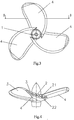
- shows a front view of a first embodiment of an axial flow impeller according to the present invention having a front cover blade and a rear cover blade,
- Fig. 4
- shows a cross sectional view of
Fig.3 taken along line B-B, - Fig. 5
- shows a schematic perspective view of an axial flow impeller according to the present invention illustrated in
Fig.3 , in which a front cover blade and a rear cover blade for one of base blades are removed for clarity, - Fig. 6
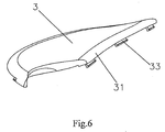
- shows a perspective view of a front cover blade of an axial flow impeller illustrated in
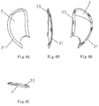
Fig.3 , - Fig. 6A
- is a front view of a front cover blade illustrated in
Fig.6 , - Fig. 6B
- is a left view of a front cover blade illustrated in
Fig.6 , - Fig. 6C
- is a top view of a front cover blade illustrated in
Fig.6 , - Fig. 6D
- is a rear view of a front cover blade illustrated in
Fig.6 , - Fig. 7
- shows a perspective view of a rear cover blade of an axial flow impeller illustrated in
Fig.5 , - Fig. 7A
- is a front view of a rear cover blade illustrated in
Fig.7 , - Fig. 7B
- is a left view of a rear cover blade illustrated in
Fig.7 , - Fig. 7C
- is a top view of a rear cover blade illustrated in
Fig.7 , and - Fig. 7D
- is a rear view of a rear cover blade illustrated in
Fig.7 . - Hereinafter, the particular embodiments of the present invention will be described in detail with reference to the drawings. It should be noted that the embodiments described herein are merely used for illustration, but not for the restriction of the invention.
- As illustrated in
Fig.3 and Fig.4 , a first embodiment of an axial flow impeller according to the present invention comprises ahub 1 and threebase blades 2 mounted around thehub 1 evenly, in which thehub 1 and thebase blades 2 can be made of stainless material, and the number of thebase blades 2 is not restricted to three and can be increased properly depending on the factors, such as a specific application circumstances and the like. The particular structures and shapes of thehub 1 and thebase blade 2 as well as the connection therebetween can adopt any existing forms. In the first embodiment of the axial flow impeller according to the present invention, afront cover blade 3 is detachably mounted in thefront 21 of eachbase blade 2, and arear cover blade 4 is detachably mounted in the rear 22 of eachbase blade 2. In this embodiment, the thicknesses of the front andrear cover blades rear cover blades rear cover blades rear cover blades rear cover blades base blade 2, and a front reinforcing envelopingedge 31 can be formed integrally on the outer edge of thefront cover blade 3, and a rear reinforcing envelopingedge 41 can be formed integrally on the outer edge of therear cover blade 4. The front reinforcing envelopingedge 31 of thefront cover blade 3 and the rear reinforcing envelopingedge 41 of therear cover blade 4 are contacted and fitted with each other on the opposing sides thereof. Moreover, after the front and rear reinforcing enveloping edges 31, 41 are fitted with each other, the resulting whole outer surface has a smooth transition shape. Thus, thebase blade 2 is enclosed within a space formed by the front andrear cover blades front cover blade 3 and the front reinforcing envelopingedge 31 thereof as well as therear cover blade 4 and the rear reinforcing envelopingedge 41 thereof. Therefore, the shape of the outer surface of the axial flow impeller blade with the front andrear cover blades rear cover blades - In this embodiment, the front and
rear cover blades base blade 2 by means of various manners. For example, thefront cover blade 3 or therear cover blade 4 can be mounted on thebase blade 2 by means of several blots and nuts. In addition, the front andrear cover blades - As illustrated in
Fig.5 ,Fig. 6 ,Figs.6A to 6D ,Fig.7 andFigs.7A to 7D , in the rear of thefront cover blade 3, i.e. in a surface in proximity to thebase blade 2, there are evenly provided several hooks 33 (seeFig. 6 ); and thehooks 33 can be formed integrally with thefront cover blade 3, or be fixed on thebase blade 2 by means of other manners such as adhering, welding and the like. Preferably, thehooks 33 are formed on the front reinforcing envelopingedge 31. Several slits are provided on therear cover blade 4 in positions corresponding to those positions where several hooks of thefront cover blade 3 are located, respectively. When thehooks 33 are formed on the front reinforcing envelopingedge 31, theslits 43 are formed on the rear reinforcing envelopingedge 41 of therear cover blade 4. The front andrear cover blades hooks 33 and slits 43 thereof with each other; and the front andrear cover blades respective hooks 33 from theslits 43. Therefore, assembly and disassembly of the front andrear cover blades - The axial flow propeller according to the present invention takes the
base blade 2 as its carrier, and the cover blades are detachably mounted in the front and the rear of the base blade, thereby the outer profile shape of the axial flow impeller blade can be varied by changing the profile of the cover blade, such that single axial flow impeller can provide different efficiencies. Furthermore, in the axial flow propeller according to the present invention, it is also allowable to meet the requirements for different application circumstances by changing the material of the cover blade. For example, the cover blade made of plastic can be used in a liquid with high PH value or containing particular components or municipal sewage or water, and the cover blade made of stainless material can be used in an industry sewage having high density and viscosity. - The axial flow propeller according to the present invention can be widely applicable to the products, such as a stirrer, a flow impeller, an axial flow device and a submersible circulating pump and the like.
- The above-described embodiments are not restricted to any detail set forth above, and should be construed within the scope defined by the appended claims.
Claims (9)
- An axial flow impeller comprising a hub (1) and at least three base blades (2) mounted around the hub (1) evenly and capable of doing work on an external object, with a cover blade detachably mounted on each base blade (2), whereas a front cover blade (3) is detachably mounted in the front of each base blade and a rear cover blade (4) is detachably mounted in the rear of each base blade, characterized in that the outer edge of each of the cover blades is provided with a reinforcing enveloping edge (31, 41) and in that said reinforcing enveloping edges (31, 41) of the two cover blades (3,4) are contacted and detachably fitted with each other on the opposing sides, such that the base blade (2) is enclosed within a space formed by the two cover blades.
- The axial flow impeller as set forth in claim 1, characterized in that the hub (1) and the base blade (2) are made of a stainless material.
- The axial flow impeller as set forth in claim 1 or 2, characterized in that the cover blade is made of a plastic or stainless material.
- The axial flow impeller as set forth in any one of the claims 1 - 3, characterized in that the thickness of the cover blade is uniform and the outer edge of the cover blade has a smooth transition shape.
- The axial flow impeller as set forth in any one of the claims 1 to 4, characterized in that the shapes of the cover blades conform to the shape of the base blade (2).
- The axial flow impeller as set forth in any one of the claims 1 - 5, characterized in that several hooks are evenly arranged on the cover blade, and several slits cooperating with the several hooks are arranged on the base blade (2) in positions corresponding to those positions where the several hooks of the cover blade are located.
- The axial flow impeller as set forth in any one of the claims 1 - 6,
characterized in that several hook (33) are evenly arranged on the cover blade (3) positioned in the front or rear of the base blade (2), and several slit (43) cooperating with the several hooks (33) are arranged correspondingly on the cover blade (4) positioned in the rear or front of the base blade (2). - The axial flow impeller as set forth in claim 7, characterized in that the hooks (33) and slits (43) are arranged on the reinforcing enveloping edges (31,41) of the cover blades (3,4) respectively.
- The axial flow impeller as set forth in any one of the claims 1 - 8.
characterized in that the cover blades (3,4) are mounted on the base blade (2) by means of several blots and nuts.
Applications Claiming Priority (2)
| Application Number | Priority Date | Filing Date | Title |
|---|---|---|---|
| CN2010102849560A CN102062121B (en) | 2010-09-16 | 2010-09-16 | Axial flow impeller |
| PCT/EP2011/065845 WO2012035008A2 (en) | 2010-09-16 | 2011-09-13 | Axial flow impeller |
Publications (2)
| Publication Number | Publication Date |
|---|---|
| EP2616689A2 EP2616689A2 (en) | 2013-07-24 |
| EP2616689B1 true EP2616689B1 (en) | 2016-08-17 |
Family
ID=43997550
Family Applications (1)
| Application Number | Title | Priority Date | Filing Date |
|---|---|---|---|
| EP11757843.5A Active EP2616689B1 (en) | 2010-09-16 | 2011-09-13 | Axial flow impeller |
Country Status (5)
| Country | Link |
|---|---|
| US (1) | US9435349B2 (en) |
| EP (1) | EP2616689B1 (en) |
| CN (1) | CN102062121B (en) |
| ES (1) | ES2600702T3 (en) |
| WO (1) | WO2012035008A2 (en) |
Families Citing this family (2)
| Publication number | Priority date | Publication date | Assignee | Title |
|---|---|---|---|---|
| US10480527B2 (en) | 2017-05-05 | 2019-11-19 | Robert Bosch Gmbh | Axial fan with unbalanced blade spacing |
| CN108126554A (en) * | 2018-02-01 | 2018-06-08 | 海斯特(青岛)泵业有限公司 | A kind of axial-flow type Anti-twisting mixer impeller |
Family Cites Families (23)
| Publication number | Priority date | Publication date | Assignee | Title |
|---|---|---|---|---|
| US2033345A (en) * | 1931-03-04 | 1936-03-10 | Roger K Lee | Fan blade |
| US2077959A (en) * | 1935-08-16 | 1937-04-20 | Bendix Prod Corp | Fan blade |
| US2949092A (en) * | 1959-03-09 | 1960-08-16 | Donald A Fortune | Propeller shroud |
| US2990889A (en) * | 1959-10-19 | 1961-07-04 | Merrell V Welch | Propeller blade sock |
| US3891349A (en) * | 1972-02-22 | 1975-06-24 | Wallace Murray Corp | Cooling fan construction and method of making same |
| SE7701530L (en) * | 1976-02-21 | 1977-08-22 | Mtu Muenchen Gmbh | IN DRIVE INSTALLATION COMPONENT, SPECIFICALLY A TURBINE BLOOD |
| US4161056A (en) * | 1977-08-05 | 1979-07-17 | P.R.K., Inc. | Method and device for repairing damaged screw propellers |
| US4636142A (en) * | 1984-05-11 | 1987-01-13 | Household Manufacturing, Inc. | Rotating fan apparatus |
| US4738594A (en) * | 1986-02-05 | 1988-04-19 | Ishikawajima-Harima Jukogyo Kabushiki Kaisha | Blades for axial fans |
| JPS6386400U (en) * | 1986-11-26 | 1988-06-06 | ||
| US4895491A (en) * | 1988-06-17 | 1990-01-23 | Environmental Elements Corp. | Fan blade protection system |
| US5273399A (en) * | 1990-08-17 | 1993-12-28 | Ojeda Christopher M | Reflective propeller cover |
| US5281093A (en) | 1991-02-21 | 1994-01-25 | Sedlak Lois M | Fan blade cover |
| CN2101127U (en) * | 1991-09-08 | 1992-04-08 | 邱绍雄 | Protective case for ceiling fan |
| CN2144724Y (en) * | 1992-11-25 | 1993-10-27 | 廖忠义 | Ceiling fan with multi-stage stepped blade structure |
| GB2293631B (en) | 1994-09-30 | 1998-09-09 | Gen Electric | Composite fan blade trailing edge reinforcement |
| US5527193A (en) * | 1995-01-18 | 1996-06-18 | Doelcher; Jack R. | Covers for boat blades of propellers of in-board and outboard boat motors |
| US5591006A (en) * | 1995-11-27 | 1997-01-07 | Demeo; Paul J. | Decorative cover for ceiling fan blade |
| US6019479A (en) * | 1996-09-26 | 2000-02-01 | Barker; Dale E. | Multi-fastening, one-piece, decorative fan blade cover and strobe light |
| US6132520A (en) * | 1998-07-30 | 2000-10-17 | Howmet Research Corporation | Removal of thermal barrier coatings |
| DE10052637B4 (en) * | 2000-10-24 | 2021-03-11 | Pfeiffer Vacuum Gmbh | 02/16/2001 Discs for a turbo molecular pump |
| US7056090B1 (en) * | 2003-04-09 | 2006-06-06 | Kathleen Stengel | Ceiling fan blade cover |
| CN2627251Y (en) * | 2003-05-26 | 2004-07-21 | 杨圣安 | Combined fan blades for cooling fans |
-
2010
- 2010-09-16 CN CN2010102849560A patent/CN102062121B/en active Active
-
2011
- 2011-09-13 ES ES11757843.5T patent/ES2600702T3/en active Active
- 2011-09-13 US US13/823,447 patent/US9435349B2/en not_active Expired - Fee Related
- 2011-09-13 WO PCT/EP2011/065845 patent/WO2012035008A2/en not_active Ceased
- 2011-09-13 EP EP11757843.5A patent/EP2616689B1/en active Active
Also Published As
| Publication number | Publication date |
|---|---|
| WO2012035008A2 (en) | 2012-03-22 |
| CN102062121A (en) | 2011-05-18 |
| WO2012035008A3 (en) | 2012-05-24 |
| EP2616689A2 (en) | 2013-07-24 |
| CN102062121B (en) | 2013-03-27 |
| US9435349B2 (en) | 2016-09-06 |
| US20130236328A1 (en) | 2013-09-12 |
| ES2600702T3 (en) | 2017-02-10 |
Similar Documents
| Publication | Publication Date | Title |
|---|---|---|
| USD589138S1 (en) | Motor assembly | |
| USD570471S1 (en) | Part of a propeller for an axial flow fan | |
| USD564653S1 (en) | Propeller for an axial flow fan | |
| USD558324S1 (en) | Overlapping fan-blade structure for a fan wheel | |
| USD633435S1 (en) | Tire | |
| CA2286705A1 (en) | Improved fluid displacing blade | |
| USD516583S1 (en) | Pump | |
| CA2256272A1 (en) | A pump impeller hub | |
| USD607093S1 (en) | Radiator for heating | |
| DE59800172D1 (en) | Cooling air flow in a turbine impeller disk | |
| USD552758S1 (en) | One-piece molded mosaic tile system | |
| USD562781S1 (en) | Fan with ribbed housing sidewalls | |
| US6106232A (en) | Propeller structure | |
| USD413378S (en) | Combined ceiling fan and light fixture | |
| ES2600702T3 (en) | Axial flow impeller | |
| USD650529S1 (en) | Patterned heat reflective material | |
| USD516194S1 (en) | Axial fan with double impellers rotating in mutually opposite directions | |
| CN222415356U (en) | Fan with fan wheel printing layer | |
| USD475338S1 (en) | Motor boat | |
| USD452786S1 (en) | Credenza top | |
| CA2024888A1 (en) | Torque converter turbine | |
| USD474203S1 (en) | Riding trowel with rotatable ring edge guard | |
| TW200722629A (en) | Fan and impeller thereof | |
| DE60307180D1 (en) | Helicopter rotor hub, and rotor with such a hub | |
| WO2007008065A1 (en) | Method of framing a carrier of visual information, set comprising a piano and a holder, a piano and a holder |
Legal Events
| Date | Code | Title | Description |
|---|---|---|---|
| PUAI | Public reference made under article 153(3) epc to a published international application that has entered the european phase |
Free format text: ORIGINAL CODE: 0009012 |
|
| 17P | Request for examination filed |
Effective date: 20130313 |
|
| AK | Designated contracting states |
Kind code of ref document: A2 Designated state(s): AL AT BE BG CH CY CZ DE DK EE ES FI FR GB GR HR HU IE IS IT LI LT LU LV MC MK MT NL NO PL PT RO RS SE SI SK SM TR |
|
| DAX | Request for extension of the european patent (deleted) | ||
| GRAP | Despatch of communication of intention to grant a patent |
Free format text: ORIGINAL CODE: EPIDOSNIGR1 |
|
| INTG | Intention to grant announced |
Effective date: 20160405 |
|
| GRAS | Grant fee paid |
Free format text: ORIGINAL CODE: EPIDOSNIGR3 |
|
| GRAA | (expected) grant |
Free format text: ORIGINAL CODE: 0009210 |
|
| AK | Designated contracting states |
Kind code of ref document: B1 Designated state(s): AL AT BE BG CH CY CZ DE DK EE ES FI FR GB GR HR HU IE IS IT LI LT LU LV MC MK MT NL NO PL PT RO RS SE SI SK SM TR |
|
| REG | Reference to a national code |
Ref country code: GB Ref legal event code: FG4D |
|
| REG | Reference to a national code |
Ref country code: FR Ref legal event code: PLFP Year of fee payment: 6 |
|
| REG | Reference to a national code |
Ref country code: CH Ref legal event code: EP |
|
| REG | Reference to a national code |
Ref country code: IE Ref legal event code: FG4D |
|
| REG | Reference to a national code |
Ref country code: AT Ref legal event code: REF Ref document number: 821399 Country of ref document: AT Kind code of ref document: T Effective date: 20160915 |
|
| REG | Reference to a national code |
Ref country code: DE Ref legal event code: R096 Ref document number: 602011029367 Country of ref document: DE |
|
| REG | Reference to a national code |
Ref country code: NL Ref legal event code: MP Effective date: 20160817 |
|
| REG | Reference to a national code |
Ref country code: LT Ref legal event code: MG4D |
|
| REG | Reference to a national code |
Ref country code: AT Ref legal event code: MK05 Ref document number: 821399 Country of ref document: AT Kind code of ref document: T Effective date: 20160817 |
|
| PG25 | Lapsed in a contracting state [announced via postgrant information from national office to epo] |
Ref country code: RS Free format text: LAPSE BECAUSE OF FAILURE TO SUBMIT A TRANSLATION OF THE DESCRIPTION OR TO PAY THE FEE WITHIN THE PRESCRIBED TIME-LIMIT Effective date: 20160817 Ref country code: HR Free format text: LAPSE BECAUSE OF FAILURE TO SUBMIT A TRANSLATION OF THE DESCRIPTION OR TO PAY THE FEE WITHIN THE PRESCRIBED TIME-LIMIT Effective date: 20160817 Ref country code: LT Free format text: LAPSE BECAUSE OF FAILURE TO SUBMIT A TRANSLATION OF THE DESCRIPTION OR TO PAY THE FEE WITHIN THE PRESCRIBED TIME-LIMIT Effective date: 20160817 Ref country code: FI Free format text: LAPSE BECAUSE OF FAILURE TO SUBMIT A TRANSLATION OF THE DESCRIPTION OR TO PAY THE FEE WITHIN THE PRESCRIBED TIME-LIMIT Effective date: 20160817 Ref country code: NO Free format text: LAPSE BECAUSE OF FAILURE TO SUBMIT A TRANSLATION OF THE DESCRIPTION OR TO PAY THE FEE WITHIN THE PRESCRIBED TIME-LIMIT Effective date: 20161117 Ref country code: NL Free format text: LAPSE BECAUSE OF FAILURE TO SUBMIT A TRANSLATION OF THE DESCRIPTION OR TO PAY THE FEE WITHIN THE PRESCRIBED TIME-LIMIT Effective date: 20160817 |
|
| REG | Reference to a national code |
Ref country code: ES Ref legal event code: FG2A Ref document number: 2600702 Country of ref document: ES Kind code of ref document: T3 Effective date: 20170210 |
|
| PG25 | Lapsed in a contracting state [announced via postgrant information from national office to epo] |
Ref country code: AT Free format text: LAPSE BECAUSE OF FAILURE TO SUBMIT A TRANSLATION OF THE DESCRIPTION OR TO PAY THE FEE WITHIN THE PRESCRIBED TIME-LIMIT Effective date: 20160817 Ref country code: PT Free format text: LAPSE BECAUSE OF FAILURE TO SUBMIT A TRANSLATION OF THE DESCRIPTION OR TO PAY THE FEE WITHIN THE PRESCRIBED TIME-LIMIT Effective date: 20161219 Ref country code: PL Free format text: LAPSE BECAUSE OF FAILURE TO SUBMIT A TRANSLATION OF THE DESCRIPTION OR TO PAY THE FEE WITHIN THE PRESCRIBED TIME-LIMIT Effective date: 20160817 Ref country code: SE Free format text: LAPSE BECAUSE OF FAILURE TO SUBMIT A TRANSLATION OF THE DESCRIPTION OR TO PAY THE FEE WITHIN THE PRESCRIBED TIME-LIMIT Effective date: 20160817 Ref country code: LV Free format text: LAPSE BECAUSE OF FAILURE TO SUBMIT A TRANSLATION OF THE DESCRIPTION OR TO PAY THE FEE WITHIN THE PRESCRIBED TIME-LIMIT Effective date: 20160817 Ref country code: GR Free format text: LAPSE BECAUSE OF FAILURE TO SUBMIT A TRANSLATION OF THE DESCRIPTION OR TO PAY THE FEE WITHIN THE PRESCRIBED TIME-LIMIT Effective date: 20161118 Ref country code: BE Free format text: LAPSE BECAUSE OF NON-PAYMENT OF DUE FEES Effective date: 20160930 |
|
| PG25 | Lapsed in a contracting state [announced via postgrant information from national office to epo] |
Ref country code: RO Free format text: LAPSE BECAUSE OF FAILURE TO SUBMIT A TRANSLATION OF THE DESCRIPTION OR TO PAY THE FEE WITHIN THE PRESCRIBED TIME-LIMIT Effective date: 20160817 Ref country code: EE Free format text: LAPSE BECAUSE OF FAILURE TO SUBMIT A TRANSLATION OF THE DESCRIPTION OR TO PAY THE FEE WITHIN THE PRESCRIBED TIME-LIMIT Effective date: 20160817 |
|
| REG | Reference to a national code |
Ref country code: CH Ref legal event code: PL |
|
| REG | Reference to a national code |
Ref country code: DE Ref legal event code: R097 Ref document number: 602011029367 Country of ref document: DE |
|
| PG25 | Lapsed in a contracting state [announced via postgrant information from national office to epo] |
Ref country code: CZ Free format text: LAPSE BECAUSE OF FAILURE TO SUBMIT A TRANSLATION OF THE DESCRIPTION OR TO PAY THE FEE WITHIN THE PRESCRIBED TIME-LIMIT Effective date: 20160817 Ref country code: SK Free format text: LAPSE BECAUSE OF FAILURE TO SUBMIT A TRANSLATION OF THE DESCRIPTION OR TO PAY THE FEE WITHIN THE PRESCRIBED TIME-LIMIT Effective date: 20160817 Ref country code: SM Free format text: LAPSE BECAUSE OF FAILURE TO SUBMIT A TRANSLATION OF THE DESCRIPTION OR TO PAY THE FEE WITHIN THE PRESCRIBED TIME-LIMIT Effective date: 20160817 Ref country code: BE Free format text: LAPSE BECAUSE OF FAILURE TO SUBMIT A TRANSLATION OF THE DESCRIPTION OR TO PAY THE FEE WITHIN THE PRESCRIBED TIME-LIMIT Effective date: 20160817 Ref country code: DK Free format text: LAPSE BECAUSE OF FAILURE TO SUBMIT A TRANSLATION OF THE DESCRIPTION OR TO PAY THE FEE WITHIN THE PRESCRIBED TIME-LIMIT Effective date: 20160817 Ref country code: BG Free format text: LAPSE BECAUSE OF FAILURE TO SUBMIT A TRANSLATION OF THE DESCRIPTION OR TO PAY THE FEE WITHIN THE PRESCRIBED TIME-LIMIT Effective date: 20161117 |
|
| PLBE | No opposition filed within time limit |
Free format text: ORIGINAL CODE: 0009261 |
|
| STAA | Information on the status of an ep patent application or granted ep patent |
Free format text: STATUS: NO OPPOSITION FILED WITHIN TIME LIMIT |
|
| REG | Reference to a national code |
Ref country code: IE Ref legal event code: MM4A |
|
| PG25 | Lapsed in a contracting state [announced via postgrant information from national office to epo] |
Ref country code: MC Free format text: LAPSE BECAUSE OF FAILURE TO SUBMIT A TRANSLATION OF THE DESCRIPTION OR TO PAY THE FEE WITHIN THE PRESCRIBED TIME-LIMIT Effective date: 20160817 |
|
| REG | Reference to a national code |
Ref country code: FR Ref legal event code: PLFP Year of fee payment: 7 |
|
| 26N | No opposition filed |
Effective date: 20170518 |
|
| GBPC | Gb: european patent ceased through non-payment of renewal fee |
Effective date: 20161117 |
|
| PG25 | Lapsed in a contracting state [announced via postgrant information from national office to epo] |
Ref country code: CH Free format text: LAPSE BECAUSE OF NON-PAYMENT OF DUE FEES Effective date: 20160930 Ref country code: IE Free format text: LAPSE BECAUSE OF NON-PAYMENT OF DUE FEES Effective date: 20160913 Ref country code: LI Free format text: LAPSE BECAUSE OF NON-PAYMENT OF DUE FEES Effective date: 20160930 |
|
| PG25 | Lapsed in a contracting state [announced via postgrant information from national office to epo] |
Ref country code: LU Free format text: LAPSE BECAUSE OF NON-PAYMENT OF DUE FEES Effective date: 20160913 Ref country code: SI Free format text: LAPSE BECAUSE OF FAILURE TO SUBMIT A TRANSLATION OF THE DESCRIPTION OR TO PAY THE FEE WITHIN THE PRESCRIBED TIME-LIMIT Effective date: 20160817 |
|
| PG25 | Lapsed in a contracting state [announced via postgrant information from national office to epo] |
Ref country code: GB Free format text: LAPSE BECAUSE OF NON-PAYMENT OF DUE FEES Effective date: 20161117 |
|
| PG25 | Lapsed in a contracting state [announced via postgrant information from national office to epo] |
Ref country code: CY Free format text: LAPSE BECAUSE OF FAILURE TO SUBMIT A TRANSLATION OF THE DESCRIPTION OR TO PAY THE FEE WITHIN THE PRESCRIBED TIME-LIMIT Effective date: 20160817 Ref country code: HU Free format text: LAPSE BECAUSE OF FAILURE TO SUBMIT A TRANSLATION OF THE DESCRIPTION OR TO PAY THE FEE WITHIN THE PRESCRIBED TIME-LIMIT; INVALID AB INITIO Effective date: 20110913 |
|
| PG25 | Lapsed in a contracting state [announced via postgrant information from national office to epo] |
Ref country code: IS Free format text: LAPSE BECAUSE OF FAILURE TO SUBMIT A TRANSLATION OF THE DESCRIPTION OR TO PAY THE FEE WITHIN THE PRESCRIBED TIME-LIMIT Effective date: 20160817 Ref country code: MT Free format text: LAPSE BECAUSE OF NON-PAYMENT OF DUE FEES Effective date: 20160930 Ref country code: TR Free format text: LAPSE BECAUSE OF FAILURE TO SUBMIT A TRANSLATION OF THE DESCRIPTION OR TO PAY THE FEE WITHIN THE PRESCRIBED TIME-LIMIT Effective date: 20160817 Ref country code: MK Free format text: LAPSE BECAUSE OF FAILURE TO SUBMIT A TRANSLATION OF THE DESCRIPTION OR TO PAY THE FEE WITHIN THE PRESCRIBED TIME-LIMIT Effective date: 20160817 |
|
| REG | Reference to a national code |
Ref country code: FR Ref legal event code: PLFP Year of fee payment: 8 |
|
| PG25 | Lapsed in a contracting state [announced via postgrant information from national office to epo] |
Ref country code: AL Free format text: LAPSE BECAUSE OF FAILURE TO SUBMIT A TRANSLATION OF THE DESCRIPTION OR TO PAY THE FEE WITHIN THE PRESCRIBED TIME-LIMIT Effective date: 20160817 |
|
| REG | Reference to a national code |
Ref country code: DE Ref legal event code: R082 Ref document number: 602011029367 Country of ref document: DE |
|
| PGFP | Annual fee paid to national office [announced via postgrant information from national office to epo] |
Ref country code: DE Payment date: 20240918 Year of fee payment: 14 |
|
| PGFP | Annual fee paid to national office [announced via postgrant information from national office to epo] |
Ref country code: FR Payment date: 20240925 Year of fee payment: 14 |
|
| PGFP | Annual fee paid to national office [announced via postgrant information from national office to epo] |
Ref country code: IT Payment date: 20240924 Year of fee payment: 14 |
|
| PGFP | Annual fee paid to national office [announced via postgrant information from national office to epo] |
Ref country code: ES Payment date: 20241025 Year of fee payment: 14 |