EP2615898A1 - Vehicle heat release structure - Google Patents
Vehicle heat release structure Download PDFInfo
- Publication number
- EP2615898A1 EP2615898A1 EP12192201.7A EP12192201A EP2615898A1 EP 2615898 A1 EP2615898 A1 EP 2615898A1 EP 12192201 A EP12192201 A EP 12192201A EP 2615898 A1 EP2615898 A1 EP 2615898A1
- Authority
- EP
- European Patent Office
- Prior art keywords
- heat
- hose
- end portion
- air
- wire harness
- Prior art date
- Legal status (The legal status is an assumption and is not a legal conclusion. Google has not performed a legal analysis and makes no representation as to the accuracy of the status listed.)
- Granted
Links
- 230000003578 releasing effect Effects 0.000 claims abstract description 89
- 230000001143 conditioned effect Effects 0.000 claims description 2
- 238000010586 diagram Methods 0.000 description 18
- 238000004378 air conditioning Methods 0.000 description 13
- 238000001816 cooling Methods 0.000 description 9
- 238000013461 design Methods 0.000 description 3
- 238000011161 development Methods 0.000 description 2
- 230000000694 effects Effects 0.000 description 2
- 230000002093 peripheral effect Effects 0.000 description 2
- 229920000915 polyvinyl chloride Polymers 0.000 description 2
- 239000004800 polyvinyl chloride Substances 0.000 description 2
- 238000012360 testing method Methods 0.000 description 2
- 239000004744 fabric Substances 0.000 description 1
- 239000000446 fuel Substances 0.000 description 1
- 230000002452 interceptive effect Effects 0.000 description 1
- 238000000034 method Methods 0.000 description 1
- 238000012986 modification Methods 0.000 description 1
- 230000004048 modification Effects 0.000 description 1
- 238000012546 transfer Methods 0.000 description 1
- 238000004804 winding Methods 0.000 description 1
Images


Classifications
-
- H—ELECTRICITY
- H05—ELECTRIC TECHNIQUES NOT OTHERWISE PROVIDED FOR
- H05K—PRINTED CIRCUITS; CASINGS OR CONSTRUCTIONAL DETAILS OF ELECTRIC APPARATUS; MANUFACTURE OF ASSEMBLAGES OF ELECTRICAL COMPONENTS
- H05K7/00—Constructional details common to different types of electric apparatus
- H05K7/20—Modifications to facilitate cooling, ventilating, or heating
- H05K7/20845—Modifications to facilitate cooling, ventilating, or heating for automotive electronic casings
- H05K7/20863—Forced ventilation, e.g. on heat dissipaters coupled to components
-
- B—PERFORMING OPERATIONS; TRANSPORTING
- B60—VEHICLES IN GENERAL
- B60R—VEHICLES, VEHICLE FITTINGS, OR VEHICLE PARTS, NOT OTHERWISE PROVIDED FOR
- B60R16/00—Electric or fluid circuits specially adapted for vehicles and not otherwise provided for; Arrangement of elements of electric or fluid circuits specially adapted for vehicles and not otherwise provided for
- B60R16/02—Electric or fluid circuits specially adapted for vehicles and not otherwise provided for; Arrangement of elements of electric or fluid circuits specially adapted for vehicles and not otherwise provided for electric constitutive elements
-
- H—ELECTRICITY
- H05—ELECTRIC TECHNIQUES NOT OTHERWISE PROVIDED FOR
- H05K—PRINTED CIRCUITS; CASINGS OR CONSTRUCTIONAL DETAILS OF ELECTRIC APPARATUS; MANUFACTURE OF ASSEMBLAGES OF ELECTRICAL COMPONENTS
- H05K1/00—Printed circuits
- H05K1/02—Details
-
- H—ELECTRICITY
- H05—ELECTRIC TECHNIQUES NOT OTHERWISE PROVIDED FOR
- H05K—PRINTED CIRCUITS; CASINGS OR CONSTRUCTIONAL DETAILS OF ELECTRIC APPARATUS; MANUFACTURE OF ASSEMBLAGES OF ELECTRICAL COMPONENTS
- H05K7/00—Constructional details common to different types of electric apparatus
- H05K7/20—Modifications to facilitate cooling, ventilating, or heating
Definitions
- the present invention relates to a heat release structure for a vehicle supplying a heat releasing effect to a predetermined heat generator housed within a housing unit such as an ECU (Electronic Control Unit), a junction block (J/B), or the like provided in a predetermined cabin exterior region, such as a vehicle's engine compartment.
- a housing unit such as an ECU (Electronic Control Unit), a junction block (J/B), or the like provided in a predetermined cabin exterior region, such as a vehicle's engine compartment.
- Housing units such as a junction block or an ECU are generally provided to an engine compartment (vehicle exterior region in an automobile). Ordinarily, these housing units are electrically connected to an exterior via a wire harness.
- housing units In addition to ambient temperature within the engine compartment (cabin exterior region), these housing units include on an interior thereof components constituting heat generators generating heat by electric conductivity. Many components constituting heat generators require strategies for releasing heat.
- first through third heat release strategies performed as conventional heat release strategies, are described.
- Fig. 7 is an explanatory diagram showing a first conventional heat release strategy for a junction block 41.
- components such as a relay, a fuse, a circuit breaker, or the like, which are not shown in the drawing) which may constitute heat generators are placed within a housing case 50.
- the above-noted components are housed by providing a lid 51.
- a heat releasing fin 52 is provided running from an interior of the housing case 50 to an exterior on a lateral surface. Through contact with outside air, the heat releasing fin 52 supplies a heat release strategy for heat generated by the interior components.
- An example of a heat release structure with this kind of heat releasing fin 52 (heat sink) is a casing with a built-in circuit board, as disclosed in JP 2007-109993 A .
- Fig. 8 is an explanatory diagram showing a second conventional heat release strategy for a junction block 42.
- components such as a relay, a fuse, a circuit breaker, or the like, which are not shown in the drawing) which may constitute heat generators are placed within a housing case 70.
- the above-noted components are housed by providing a lid 71.
- a panel connector 72 constituting a heat transfer sheet is provided running from an interior of the housing case 70 to an exterior on a lateral surface.
- a heat releasing panel 73 having a step portion 73a on an end side is provided on an exterior exposed surface of the panel connector 72. The two surfaces of the step portion 73a form a contact surface area with the outside air, and thus the heat releasing panel 73 carries out a strategy for releasing heat generated by the interior components via the heat releasing panel 73 and the panel connector 72.
- Fig. 9 is an explanatory diagram showing a third conventional heat release strategy for an ECU 43.
- a heat generating block 64 including computer chips, for example is placed within a housing case 60.
- the heat generating block 64 is housed by providing a lid 61.
- a cooling pipe 62 and a cooling pipe 63 having comparatively large diameters are provided on one lateral surface and another lateral surface of the housing case 60.
- Air from a separately-provided, dedicated cooling fan (not depicted) is forced in through the cooling pipe 62 and then forced out through the cooling pipe 63.
- a heat release strategy is performed for heat generated by the heat generating block 64.
- a cooling fan is provided, for example, to the engine compartment (cabin exterior region).
- the first and second conventional heat releasing strategies described above achieve a heat releasing effect through contact with outside air by a dedicated heat releasing component (the heat releasing fin 52, the heat releasing panel 73, and the like), and are therefore problematic in that costs increase accordingly.
- the above-described heat-releasing components must be made large enough to absolutely ensure a contact surface area necessary for heat release and, in addition, must avoid interfering with other exterior components when put in place. Accordingly, the first and second heat releasing strategies are problematic as regards the size and placement of heat releasing components, in that limitations on vehicle mounting are significant.
- the third conventional heat release strategy described above requires that a dedicated cooling fan and the cooling pipes 62 and 63 having comparatively large diameters be provided as dedicated heat releasing components.
- the third conventional heat release strategy is therefore problematic in that a configuration of the heat release structure becomes complicated and costs more.
- the present invention is conceived to resolve the above issues and has as an object to obtain, with a simple configuration and without inviting limitations on vehicle mounting, a heat release structure for a vehicle capable of a heat release strategy for a heat generator.
- the heat release structure for a vehicle is a heat release structure for a vehicle for a heat generator provided in a cabin exterior region of the vehicle.
- the heat release structure includes a wire harness positioned so as to run from the cabin exterior region to a cabin interior and a heat releasing hose having a first end portion, a main portion, and a second end portion in which the main portion is integrally mounted in the wire harness.
- the first end portion of the heat releasing hose is positioned within the cabin exterior region and the second end portion of the heat releasing hose is positioned in the cabin interior.
- the predetermined condition includes an air pressure differential arising between the cabin interior and the vehicle exterior region due to air pressure inside the cabin becoming lower than that of the vehicle exterior region.
- the cabin interior includes an air conditioned region having an air conditioner.
- the air conditioner has a cabin interior air intake ability, taking in air of the cabin interior via an intake hose while active.
- the second end portion can be connected so as to flow into a middle portion of the intake hose.
- the predetermined condition includes a case where the air conditioner is active.
- the heat generator includes a heat generator housed within a housing unit.
- the heat release structure for the vehicle further includes an auxiliary hose in which a first terminus is positioned adjacent to the heat generator inside the housing unit and a second terminus is positioned outside the housing unit. The first end portion is connected to the second terminus of the auxiliary hose such that heated air can flow therethrough.
- the heat release structure for the vehicle further includes - according to an other (fifth) aspect of the invention - a wire harness connection provided at a foremost end of the at least one bundle of electric wires and a unit connection provided to the housing unit and capable of linking with the wire harness connection.
- the unit connection includes an opening capable of expelling heated air from the heat generator.
- the wire harness connection includes a heat releasing hose connection terminal capable of connecting to the first end portion of the heat releasing hose. When the unit connection and the wire harness connection are linked, the first end portion connected to the wire harness connection allows air within the housing unit to flow through the opening.
- the housing unit includes an ECU.
- the housing unit may include a junction block.
- the heat release structure according to the present invention is thus characterized by the intake of heated air in the vicinity of the heat generator by the first end portion and the expulsion via the main portion of the heated air to the cabin interior from the second end portion being enabled when the predetermined condition is satisfied. Therefore, when the predetermined condition is satisfied, a heat releasing effect on the heat generator is realized.
- the "heat generator” may be a heat generating unit or units of whatsoever kind and nature. It may hereinafter also be regarded as a "predetermined heat generator", however thereby not restricting kind, number, exact location etc. of such a heat generator(s).
- a wire harness to be positioned running from the cabin exterior region to the cabin interior is employed as the wire harness described above.
- heat can be released from the (predetermined) heat generator with a comparatively simple configuration where the only structural element required in practice is the heat releasing hose, the main portion of which is integrally mounted in the wire harness.
- dedicated heat releasing components such as a heat releasing fin or a heat releasing fan become unnecessary, and thus a heat release structure for a vehicle can be achieved with a comparatively low-cost configuration without inviting limitations on vehicle mounting.
- the heat release structure of the present invention according to the second aspect enables a heat releasing effect to be realized without providing a special heated air intake ability by employing an air pressure differential arising between the cabin interior and the vehicle exterior region while the vehicle is moving.
- the present invention according to the second aspect thus enables an effective heat releasing effect with a low-cost configuration to be realized by employing an intake hose used by an air conditioner.
- the first end portion of the heat releasing hose in the present invention according to the fourth aspect is connected so as to enable airflow therethrough to the second terminus of the auxiliary hose, the first terminus of which is positioned adjacent to the heat generator.
- a heat releasing effect can be effectively realized for the heat generator itself provided within the housing unit.
- the heat release structure in the present invention enables an effective heat releasing effect to be realized with a comparatively simple structure and in which attachment of a first end portion to the housing unit is easy.
- the present invention according to the sixth and seventh aspects enables a heat releasing effect to be realized for the heat generator housed in the housing unit such as an ECU or a junction block.
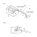
- Fig. 1 is an explanatory diagram showing a schematic configuration of a heat release structure for a vehicle, which is embodiment 1 of the present invention.
- Fig. 2 is an explanatory diagram showing a frame view of a hose connection structure adjacent to a first end portion of a heat releasing hose.
- a heat release structure for a vehicle in embodiment 1 is configured with a heat releasing hose 1 and a wire harness 21.
- the heat releasing hose 1 is configured with a first end portion 1 a (first end portion); a main portion 1 m (middle portion); and a second end portion 1 b (second end portion).
- first end portion 1a refers to a region of a predetermined length from a foremost end on a first side of the heat releasing hose 1
- the second end portion 1 b refers to a region of a predetermined length from a foremost end on a second side of the heat releasing hose 1.
- the wire harness 21 is threaded from a cabin exterior 30 to a cabin interior 31.
- the heat releasing hose 1 is provided by integrally mounting the main portion 1 m in the wire harness 21 in any suitable manner, such as by tape winding.
- a housing unit 4 is positioned within a storage box 5 on the cabin exterior 30 in an engine compartment or the like.
- a heat generator 4h which is a component such as a computer chip or a relay, is housed within the housing unit 4.
- a first end or terminus of an auxiliary hose 12 is positioned adjacent to the heat generator 4h and a second end or terminus of the auxiliary hose 12 is positioned outside the housing unit 4 through e.g. one lateral surface.
- examples of the housing unit 4 include any unit which houses a component which may constitute the heat generator 4h, such as an engine control ECU, a junction block, a relay block (R/B), an antilock brake ECU, and a fuel pump resistor.
- a component which may constitute the heat generator 4h such as an engine control ECU, a junction block, a relay block (R/B), an antilock brake ECU, and a fuel pump resistor.
- the first end portion 1 a of the heat releasing hose 1 branches from the wire harness 21 within an engine compartment 10 and is connected with the second terminus of the auxiliary hose 12 provided to a lateral surface of the housing unit 4, the first end portion 1 a connected such that heated air in the vicinity of the heat generator 4h can pass therethrough.
- the second end portion 1b of the heat releasing hose 1 is positioned in a predetermined location in the cabin interior 31 (a location in the cabin interior 31 where air can be expelled).
- Fig. 3 is an explanatory diagram showing details of the heat releasing hose 1 in each of the engine compartment 10 interior and the cabin interior 31, and the vicinity thereof.
- Fig. 4 is an explanatory diagram showing a frame view of a structure, viewing the engine compartment 10 from a direction d1 in Fig. 3 .
- the wire harness 21 in which bundles of electric wires 23a to 23c, each of which is wrapped with tape, are bundled by e.g. being further wrapped with tape, and the main portion 1 m are further wrapped with a tape 22 and are thereby integrally mounted.
- An integrated body 20 of the heat releasing hose 1 and the wire harness 21 is provided running from the engine compartment 10 (cabin exterior 30) to the cabin interior 31.
- connections 24a to 24c are provided to foremost ends of the bundles of electric wires 23a to 23c exposed from the tape 22.
- a connector 11 having connections 11a to 11c is provided to a lateral surface of the housing unit 4.
- the first end portion 1 a of the heat releasing hose 1 is exposed from the tape 22 and branches from the bundles of electric wires 23a to 23c.
- An auxiliary hose terminus 12t stands upright on the lateral surface of the housing unit 4.
- the second end portion 1 b is exposed from the tape 22 and branched from the wire harness 21 into an open state, and thus is enabled to expel air into the cabin interior 31.
- the heat generator 4h which is a heat generating component such as a computer chip or a relay, is mounted on a board 4B within the housing unit 4.
- An air vent 13 configured by adhering a waterproof but vapour permeable fabric thereto is included on the housing unit 4, which is able to continuously take in air from the exterior.
- the air vent 13 is provided so that the outside air and air pressure within the housing unit 4 are constant.
- the engine compartment 10, within which the housing unit 4 is provided also includes a gap which is capable of continuously taking in air.
- the housing unit 4 can take air in through the outside air vent 13 and the engine compartment 10 includes a gap. Therefore, while the vehicle is moving, air continuously flows from the housing unit 4 to the cabin interior 31. Thereby, heat from the heat generator 4h within the housing unit 4 such as the ECU or the junction block can be released effectively.
- the heat release structure for the vehicle of embodiment 1 takes as a predetermined condition related to the vehicle the differential air pressure arising between the cabin interior 31 and the engine compartment 10 due to the air pressure in the cabin interior 31 becoming lower than that of the engine compartment 10 (cabin exterior 30) and can realize a heat releasing effect for the heat generator 4h when the predetermined condition is satisfied.
- the heat release structure for the vehicle of embodiment 1 can realize a heat releasing effect without providing a separate intake ability, such as a fan, for heated air from the heat generator 4h by utilizing the air pressure differential arising between the chamber interior 31 and the engine compartment 10 that necessarily arises when the vehicle is in motion.
- the wire harness 21 is a wire harness originally intended for threading from the engine compartment 10 (the predetermined cabin exterior region) to the cabin interior 31. Therefore, the heat releasing hose 1, the main portion 1 m of which is integrally mounted to the wire harness 21, and the auxiliary hose 12 are the only structural elements required in practice for the heat release structure for the vehicle.
- the heat releasing hose 1 and the auxiliary hose 12 may be achieved at a comparatively low cost.
- PVC Polyvinyl Chloride
- the heat release structure for the vehicle of embodiment 1 can be achieved at a basic level. Therefore, a dedicated design for the heat releasing hose 1 is unnecessary and the heat release structure for the vehicle can be designed without requiring commensurate development costs.
- the heat release structure for the vehicle of embodiment 1 can release heat generated by the heat generator 4h (the predetermined heat generator) with a comparatively simple structure.
- dedicated heat releasing components such as a heat fin and a heat releasing fan become unnecessary, and thus the heat release structure for the vehicle can be achieved with a comparatively low-cost configuration without inviting limitations on vehicle mounting.
- the first end portion 1 a of the heat releasing hose 1 is connected so as to enable airflow therethrough to the second terminus of the auxiliary hose 12 (auxiliary hose terminus 12t), which is an auxiliary hose in which the first terminus is positioned adjacent to the heat generator 4h. Accordingly, the heated air in the vicinity of the heat generator 4h can be taken in directly, and the heat releasing effect can be achieved that much more effectively.
- Fig. 5 is an explanatory diagram showing a frame view of connector peripheral structure of a heat release structure for a vehicle, which is embodiment 2 of the present invention.
- a plurality of terminals 11t for connection with a corresponding connection 24a are provided on a connector 11a on the housing unit 4 side (unit connection), and an opening 11H is provided in a region where no terminal 11t is formed.
- positioning the second terminus of the auxiliary hose 12 adjacent to the opening 11H on the housing unit 4 is preferred.
- the first end portion 1a in embodiment 2 is configured with two first end portions 1a1 and 1 a2.
- a plurality of terminals 24t are provided on the connection 24a connected to each wire in the bundle of electric wires 23a.
- terminals 24t1 and 24t2 are provided not for the bundle of electric wires 23a, but for the first end portions 1a1 and 1 a2.
- connection to the heat releasing hose 1 is made so as to enable air within the housing unit 4 to pass therethrough.
- Other structures are similar to the heat release structure for the vehicle of embodiment 1 shown in Figs. 1 to 4 and a description thereof is therefore omitted.
- the terminals 24t1 and 24t2 may be omitted.
- the heat release structure for the vehicle of embodiment 2 employs the connection 24a for the bundle of electric wires 23a and the opening 11H provided to a portion of the connection 11a on the housing unit 4.
- the heat releasing hose 1, the main portion 1 m of which is integrally mounted to the wire harness 21, is essentially the only structural element required.
- the heat release structure for the vehicle of embodiment 2 can release heat generated by the heat generator 4h (the predetermined heat generator) with a comparatively simple configuration.
- connection 11 a and the connection 24a when electrically connecting the bundle of electric wires 23a to the housing unit 4, that is, connecting the connection 11 a and the connection 24a, the connection of the first end portions 1a1 and 1 a2 with the opening 11H can also be performed alongside. Therefore, the work of attaching the heat releasing hose 1 to the housing unit 4 can be simplified.
- Fig. 6 is an explanatory diagram showing a frame view of an air conditioning unit periphery in a cabin interior 31 for a heat release structure for a vehicle, which is embodiment 3 of the present invention.
- Embodiments 1 and 2 have a configuration in which the second end portion 1 b of the heat releasing hose 1 is placed in a predetermined location in the cabin interior 31. However, in embodiment 3, the second end portion 1 b is connected so as to flow into a sensor hose 35. This point is elaborated on below.
- a cabin interior air temperature sensor 34 is provided to an air conditioning unit 40 (predetermined air conditioner).
- the cabin interior air temperature sensor 34 is provided at an inlet of the sensor hose 35.
- cabin interior air 33 is pulled into the air conditioning unit 40 via the sensor hose 35.
- the air conditioning unit 40 includes a cabin interior air intake ability in which, while active, air flows continuously within the sensor hose 35 from the cabin interior air temperature sensor 34 toward the air conditioning unit 40.
- the second end portion 1 b of the heat releasing hose 1 is connected so as to join a hose confluence portion 36 at a middle portion of the sensor hose 35 (the intake hose).
- the air conditioning unit 40 is active, a flow of air within the heat releasing hose 1 from the first end portion 1 a to the second end portion 1 b can be continuously generated.
- other structures are similar to the heat release structure for the vehicle of embodiment 1 shown in Figs. 1 to 4 , and therefore a description thereof is omitted.
- the connection between the first end portion 1 a of the heat releasing hose 1 and the housing unit 4 may be carried out as in embodiment 2, shown in Fig. 5 .
- the heat releasing hose 1 is connected so as to join the sensor hose 35 of the air conditioning unit 40, and thus the heat releasing hose 1, the main portion 1 m of which is integrally mounted to the wire harness 21, is essentially the only structural element required.
- embodiment 3 is a case where a predetermined condition for a vehicle capable of achieving a heat releasing effect is that the air conditioning unit 40 be active.
- the heat release structure for the vehicle of embodiment 3 achieves an effect in which heat generated by the heat generator 4h (the predetermined heat generator) is released with a comparatively simple structure.
Landscapes
- Engineering & Computer Science (AREA)
- Microelectronics & Electronic Packaging (AREA)
- Physics & Mathematics (AREA)
- Thermal Sciences (AREA)
- Mechanical Engineering (AREA)
- Air-Conditioning For Vehicles (AREA)
- Cooling Or The Like Of Electrical Apparatus (AREA)
Abstract
Description
- The present invention relates to a heat release structure for a vehicle supplying a heat releasing effect to a predetermined heat generator housed within a housing unit such as an ECU (Electronic Control Unit), a junction block (J/B), or the like provided in a predetermined cabin exterior region, such as a vehicle's engine compartment. It is to be noted that the disclosure of Japanese Application No.
2012-003945, filed on January 12, 2012 - Housing units (blocks) such as a junction block or an ECU are generally provided to an engine compartment (vehicle exterior region in an automobile). Ordinarily, these housing units are electrically connected to an exterior via a wire harness.
- In addition to ambient temperature within the engine compartment (cabin exterior region), these housing units include on an interior thereof components constituting heat generators generating heat by electric conductivity. Many components constituting heat generators require strategies for releasing heat. Hereafter and with reference to
Figs. 7 to 9 of the accompanying drawings, first through third heat release strategies, performed as conventional heat release strategies, are described. -
Fig. 7 is an explanatory diagram showing a first conventional heat release strategy for ajunction block 41. As shown in the figure, in thejunction block 41 components (such as a relay, a fuse, a circuit breaker, or the like, which are not shown in the drawing) which may constitute heat generators are placed within ahousing case 50. The above-noted components are housed by providing alid 51. In addition, aheat releasing fin 52 is provided running from an interior of thehousing case 50 to an exterior on a lateral surface. Through contact with outside air, the heat releasing fin 52 supplies a heat release strategy for heat generated by the interior components. An example of a heat release structure with this kind of heat releasing fin 52 (heat sink) is a casing with a built-in circuit board, as disclosed inJP 2007-109993 A -
Fig. 8 is an explanatory diagram showing a second conventional heat release strategy for ajunction block 42. As shown in the figure, in thejunction block 42 components (such as a relay, a fuse, a circuit breaker, or the like, which are not shown in the drawing) which may constitute heat generators are placed within ahousing case 70. The above-noted components are housed by providing alid 71. Moreover, apanel connector 72 constituting a heat transfer sheet is provided running from an interior of thehousing case 70 to an exterior on a lateral surface. Aheat releasing panel 73 having a step portion 73a on an end side is provided on an exterior exposed surface of thepanel connector 72. The two surfaces of the step portion 73a form a contact surface area with the outside air, and thus theheat releasing panel 73 carries out a strategy for releasing heat generated by the interior components via theheat releasing panel 73 and thepanel connector 72. -
Fig. 9 is an explanatory diagram showing a third conventional heat release strategy for anECU 43. As shown in the figure, in the ECU 43 aheat generating block 64 including computer chips, for example, is placed within ahousing case 60. Theheat generating block 64 is housed by providing alid 61. Moreover, acooling pipe 62 and acooling pipe 63 having comparatively large diameters are provided on one lateral surface and another lateral surface of thehousing case 60. Air from a separately-provided, dedicated cooling fan (not depicted) is forced in through thecooling pipe 62 and then forced out through thecooling pipe 63. By performing an air cooling process of this kind by drawing heat, a heat release strategy is performed for heat generated by theheat generating block 64. In addition, a cooling fan is provided, for example, to the engine compartment (cabin exterior region). - However, the first and second conventional heat releasing strategies described above achieve a heat releasing effect through contact with outside air by a dedicated heat releasing component (the
heat releasing fin 52, theheat releasing panel 73, and the like), and are therefore problematic in that costs increase accordingly. - Moreover, the above-described heat-releasing components must be made large enough to absolutely ensure a contact surface area necessary for heat release and, in addition, must avoid interfering with other exterior components when put in place. Accordingly, the first and second heat releasing strategies are problematic as regards the size and placement of heat releasing components, in that limitations on vehicle mounting are significant.
- The third conventional heat release strategy described above requires that a dedicated cooling fan and the
cooling pipes - The present invention is conceived to resolve the above issues and has as an object to obtain, with a simple configuration and without inviting limitations on vehicle mounting, a heat release structure for a vehicle capable of a heat release strategy for a heat generator.
- Solution of this object is achieved by what is claimed in claim1, wherein the aspects of the subclaims contain advantageous modifications of the invention.
- Accordingly, the heat release structure for a vehicle according to the present invention is a heat release structure for a vehicle for a heat generator provided in a cabin exterior region of the vehicle. The heat release structure includes a wire harness positioned so as to run from the cabin exterior region to a cabin interior and a heat releasing hose having a first end portion, a main portion, and a second end portion in which the main portion is integrally mounted in the wire harness. The first end portion of the heat releasing hose is positioned within the cabin exterior region and the second end portion of the heat releasing hose is positioned in the cabin interior. Thereby, when a predetermined condition for the vehicle is satisfied, heated air in a vicinity of the heat generator can be taken in by the first end portion, pass through the main portion, and then be expelled to the cabin interior by the second end portion.
- Preferably and according to a further (second) aspect of the invention, the predetermined condition includes an air pressure differential arising between the cabin interior and the vehicle exterior region due to air pressure inside the cabin becoming lower than that of the vehicle exterior region.
- Preferably and according to an other (third) aspect of the invention, the cabin interior includes an air conditioned region having an air conditioner. The air conditioner has a cabin interior air intake ability, taking in air of the cabin interior via an intake hose while active. The second end portion can be connected so as to flow into a middle portion of the intake hose. The predetermined condition includes a case where the air conditioner is active.
- Preferably and according to a still further (fourth) aspect of the invention, the heat generator includes a heat generator housed within a housing unit. The heat release structure for the vehicle further includes an auxiliary hose in which a first terminus is positioned adjacent to the heat generator inside the housing unit and a second terminus is positioned outside the housing unit. The first end portion is connected to the second terminus of the auxiliary hose such that heated air can flow therethrough.
- The heat release structure for the vehicle further includes - according to an other (fifth) aspect of the invention - a wire harness connection provided at a foremost end of the at least one bundle of electric wires and a unit connection provided to the housing unit and capable of linking with the wire harness connection. The unit connection includes an opening capable of expelling heated air from the heat generator. The wire harness connection includes a heat releasing hose connection terminal capable of connecting to the first end portion of the heat releasing hose. When the unit connection and the wire harness connection are linked, the first end portion connected to the wire harness connection allows air within the housing unit to flow through the opening.
- Preferably and according to still an other (sixth) aspect of the invention the housing unit includes an ECU.
- Also preferably the housing unit may include a junction block.
- The heat release structure according to the present invention is thus characterized by the intake of heated air in the vicinity of the heat generator by the first end portion and the expulsion via the main portion of the heated air to the cabin interior from the second end portion being enabled when the predetermined condition is satisfied. Therefore, when the predetermined condition is satisfied, a heat releasing effect on the heat generator is realized. In this context it is to be noted that the "heat generator" may be a heat generating unit or units of whatsoever kind and nature. It may hereinafter also be regarded as a "predetermined heat generator", however thereby not restricting kind, number, exact location etc. of such a heat generator(s).
- A wire harness to be positioned running from the cabin exterior region to the cabin interior is employed as the wire harness described above. Thereby, heat can be released from the (predetermined) heat generator with a comparatively simple configuration where the only structural element required in practice is the heat releasing hose, the main portion of which is integrally mounted in the wire harness. As a result, dedicated heat releasing components such as a heat releasing fin or a heat releasing fan become unnecessary, and thus a heat release structure for a vehicle can be achieved with a comparatively low-cost configuration without inviting limitations on vehicle mounting.
- The heat release structure of the present invention according to the second aspect enables a heat releasing effect to be realized without providing a special heated air intake ability by employing an air pressure differential arising between the cabin interior and the vehicle exterior region while the vehicle is moving.
- The present invention according to the second aspect thus enables an effective heat releasing effect with a low-cost configuration to be realized by employing an intake hose used by an air conditioner.
- The first end portion of the heat releasing hose in the present invention according to the fourth aspect is connected so as to enable airflow therethrough to the second terminus of the auxiliary hose, the first terminus of which is positioned adjacent to the heat generator. Thus, a heat releasing effect can be effectively realized for the heat generator itself provided within the housing unit.
- By employing a unit connection and a wire harness connection generally included in a housing unit and a wire harness, respectively, the heat release structure in the present invention according to the fifth aspect enables an effective heat releasing effect to be realized with a comparatively simple structure and in which attachment of a first end portion to the housing unit is easy.
- The present invention according to the sixth and seventh aspects enables a heat releasing effect to be realized for the heat generator housed in the housing unit such as an ECU or a junction block.
- The invention now will be described in detail by way of illustrative and not limiting examples and embodiments, respectively, thereof, which are to be seen in conjunction with the accompanying drawings, in which:
-
Fig. 1 is an explanatory diagram showing a schematic configuration of a heat release structure for a vehicle, which isembodiment 1 of the present invention; -
Fig. 2 is an explanatory diagram schematically showing a hose connection structure adjacent to a first end portion of a heat releasing hose; -
Fig. 3 is an explanatory diagram showing details of the heat releasing hose in each of an engine compartment interior and a cabin interior, and the vicinity thereof; -
Fig. 4 is an explanatory diagram schematically showing an internal structure of a housing unit, viewing the engine compartment from a direction d1; -
Fig. 5 is an explanatory diagram schematically showing a connector peripheral structure in a heat release structure for a vehicle, which is embodiment 2 of the present invention; -
Fig. 6 is an explanatory diagram schematically showing an air conditioning unit periphery in the cabin interior in a heat release structure for a vehicle, which is embodiment 3 of the present invention; -
Fig. 7 is an explanatory diagram showing a first conventional heat release strategy; -
Fig. 8 is an explanatory diagram showing a second conventional heat release strategy; and -
Fig. 9 is an explanatory diagram showing a third conventional heat release strategy. -
Fig. 1 is an explanatory diagram showing a schematic configuration of a heat release structure for a vehicle, which isembodiment 1 of the present invention.Fig. 2 is an explanatory diagram showing a frame view of a hose connection structure adjacent to a first end portion of a heat releasing hose. - A heat release structure for a vehicle in
embodiment 1 is configured with aheat releasing hose 1 and awire harness 21. Theheat releasing hose 1 is configured with afirst end portion 1 a (first end portion); amain portion 1 m (middle portion); and asecond end portion 1 b (second end portion). Moreover, in the instant specification, thefirst end portion 1a refers to a region of a predetermined length from a foremost end on a first side of theheat releasing hose 1 and thesecond end portion 1 b refers to a region of a predetermined length from a foremost end on a second side of theheat releasing hose 1. - As shown in
Fig. 1 , thewire harness 21 is threaded from acabin exterior 30 to acabin interior 31. Moreover, theheat releasing hose 1 is provided by integrally mounting themain portion 1 m in thewire harness 21 in any suitable manner, such as by tape winding. - A
housing unit 4 is positioned within astorage box 5 on thecabin exterior 30 in an engine compartment or the like. As shown inFig. 2 , aheat generator 4h, which is a component such as a computer chip or a relay, is housed within thehousing unit 4. In addition, a first end or terminus of anauxiliary hose 12 is positioned adjacent to theheat generator 4h and a second end or terminus of theauxiliary hose 12 is positioned outside thehousing unit 4 through e.g. one lateral surface. - In addition, examples of the
housing unit 4 include any unit which houses a component which may constitute theheat generator 4h, such as an engine control ECU, a junction block, a relay block (R/B), an antilock brake ECU, and a fuel pump resistor. - The
first end portion 1 a of theheat releasing hose 1 branches from thewire harness 21 within anengine compartment 10 and is connected with the second terminus of theauxiliary hose 12 provided to a lateral surface of thehousing unit 4, thefirst end portion 1 a connected such that heated air in the vicinity of theheat generator 4h can pass therethrough. Thesecond end portion 1b of theheat releasing hose 1 is positioned in a predetermined location in the cabin interior 31 (a location in thecabin interior 31 where air can be expelled). -
Fig. 3 is an explanatory diagram showing details of theheat releasing hose 1 in each of theengine compartment 10 interior and thecabin interior 31, and the vicinity thereof.Fig. 4 is an explanatory diagram showing a frame view of a structure, viewing theengine compartment 10 from a direction d1 inFig. 3 . - As shown in
Fig. 3 , thewire harness 21, in which bundles ofelectric wires 23a to 23c, each of which is wrapped with tape, are bundled by e.g. being further wrapped with tape, and themain portion 1 m are further wrapped with atape 22 and are thereby integrally mounted. Anintegrated body 20 of theheat releasing hose 1 and thewire harness 21 is provided running from the engine compartment 10 (cabin exterior 30) to thecabin interior 31. - Within the
engine compartment 10,connections 24a to 24c are provided to foremost ends of the bundles ofelectric wires 23a to 23c exposed from thetape 22. Aconnector 11 havingconnections 11a to 11c is provided to a lateral surface of thehousing unit 4. By linking theconnections 24a to 24c on thewire harness 21 with theconnections 11a to 11c on thehousing unit 4, thehousing unit 4 is electrically connected to the bundles ofelectric wires 23a to 23c in thewire harness 21. - Moreover, within the
engine compartment 10, thefirst end portion 1 a of theheat releasing hose 1 is exposed from thetape 22 and branches from the bundles ofelectric wires 23a to 23c. Anauxiliary hose terminus 12t (the second terminus of the auxiliary hose 12) stands upright on the lateral surface of thehousing unit 4. By attaching an opening on the foremost end of thefirst end portion 1 a to theauxiliary hose terminus 12t, a path can be provided through which heated air in the vicinity of theheat generator 4h can pass from thehousing unit 4 via theauxiliary hose 12 and theheat releasing hose 1 to thesecond end portion 1 b in thecabin interior 31. - In the
cabin interior 31, thesecond end portion 1 b is exposed from thetape 22 and branched from thewire harness 21 into an open state, and thus is enabled to expel air into thecabin interior 31. - As shown in
Fig. 4 , theheat generator 4h, which is a heat generating component such as a computer chip or a relay, is mounted on aboard 4B within thehousing unit 4. Anair vent 13 configured by adhering a waterproof but vapour permeable fabric thereto is included on thehousing unit 4, which is able to continuously take in air from the exterior. Moreover, theair vent 13 is provided so that the outside air and air pressure within thehousing unit 4 are constant. In addition, theengine compartment 10, within which thehousing unit 4 is provided, also includes a gap which is capable of continuously taking in air. - In such a configuration, while the vehicle is in motion, the pressure within
cabin interior 31 becomes 0.1 to 0.3 atmospheres lower than in theengine compartment 10. Therefore, the heated air in the vicinity of theheat generator 4h within thehousing unit 4, which is positioned within theengine compartment 10, flows out to the cabin interior 31 from thesecond end portion 1 b via theauxiliary hose 12 and theheat releasing hose 1. Moreover, as described above, thehousing unit 4 can take air in through theoutside air vent 13 and theengine compartment 10 includes a gap. Therefore, while the vehicle is moving, air continuously flows from thehousing unit 4 to thecabin interior 31. Thereby, heat from theheat generator 4h within thehousing unit 4 such as the ECU or the junction block can be released effectively. - In addition, the heat release structure for the vehicle of
embodiment 1 takes as a predetermined condition related to the vehicle the differential air pressure arising between thecabin interior 31 and theengine compartment 10 due to the air pressure in thecabin interior 31 becoming lower than that of the engine compartment 10 (cabin exterior 30) and can realize a heat releasing effect for theheat generator 4h when the predetermined condition is satisfied. In this way, the heat release structure for the vehicle ofembodiment 1 can realize a heat releasing effect without providing a separate intake ability, such as a fan, for heated air from theheat generator 4h by utilizing the air pressure differential arising between thechamber interior 31 and theengine compartment 10 that necessarily arises when the vehicle is in motion. - Moreover, the
wire harness 21 is a wire harness originally intended for threading from the engine compartment 10 (the predetermined cabin exterior region) to thecabin interior 31. Therefore, theheat releasing hose 1, themain portion 1 m of which is integrally mounted to thewire harness 21, and theauxiliary hose 12 are the only structural elements required in practice for the heat release structure for the vehicle. - Additionally, by employing commonly used PVC (Polyvinyl Chloride) hoses as the
heat releasing hose 1 and theauxiliary hose 12, theheat releasing hose 1 and theauxiliary hose 12 may be achieved at a comparatively low cost. - When the
main portion 1 m of theheat releasing hose 1 is mounted in thewire harness 21 used for the electrical connection to thehousing unit 4, the heat release structure for the vehicle ofembodiment 1 can be achieved at a basic level. Therefore, a dedicated design for theheat releasing hose 1 is unnecessary and the heat release structure for the vehicle can be designed without requiring commensurate development costs. - By altering the hose diameter of the
heat releasing hose 1 as appropriate, an amount of air during heat drawing (flow of heated air from thehousing unit 4 to the cabin interior 31) can be altered. Therefore, tests and analysis of heat releasing effectiveness can be performed comparatively easily, and costs required for tests and analysis can accordingly be reduced. - As a result, the heat release structure for the vehicle of
embodiment 1 can release heat generated by theheat generator 4h (the predetermined heat generator) with a comparatively simple structure. In other words, dedicated heat releasing components such as a heat fin and a heat releasing fan become unnecessary, and thus the heat release structure for the vehicle can be achieved with a comparatively low-cost configuration without inviting limitations on vehicle mounting. - Additionally, as described above, dedicated heat releasing components are unnecessary, and the heat release structure for the vehicle can be obtained without relying on designs for each individual dedicated heat releasing component. Therefore, the time and effort required to rework a design when there is a change in a dedicated heat releasing component is eliminated, and thus a reduction in development costs can be achieved.
- Moreover, the
first end portion 1 a of theheat releasing hose 1 is connected so as to enable airflow therethrough to the second terminus of the auxiliary hose 12 (auxiliary hose terminus 12t), which is an auxiliary hose in which the first terminus is positioned adjacent to theheat generator 4h. Accordingly, the heated air in the vicinity of theheat generator 4h can be taken in directly, and the heat releasing effect can be achieved that much more effectively. - Furthermore, even when a configuration does not provide an
auxiliary hose 12 and simply attaches a foremost opening of thefirst end portion 1 a to one lateral surface of thehousing unit 4, air can flow continuously from thehousing unit 4 to thecabin interior 31 while the vehicle is in motion. Such a configuration is thus fully capable of achieving a heat releasing effect for theheat generator 4h within thehousing unit 4. However, from a perspective of greater heat releasing effect, providing theauxiliary hose 12 is preferred. -
Fig. 5 is an explanatory diagram showing a frame view of connector peripheral structure of a heat release structure for a vehicle, which is embodiment 2 of the present invention. - As shown in the figure, a plurality of
terminals 11t for connection with acorresponding connection 24a (connection on the wire harness) are provided on aconnector 11a on thehousing unit 4 side (unit connection), and anopening 11H is provided in a region where no terminal 11t is formed. Moreover, from the perspective of heat releasing effect, similar toembodiment 1, positioning the second terminus of theauxiliary hose 12 adjacent to theopening 11H on thehousing unit 4 is preferred. - As shown in the figure, the
first end portion 1a in embodiment 2 is configured with two first end portions 1a1 and 1 a2. A plurality ofterminals 24t are provided on theconnection 24a connected to each wire in the bundle ofelectric wires 23a. Of these, terminals 24t1 and 24t2 are provided not for the bundle ofelectric wires 23a, but for the first end portions 1a1 and 1 a2. - Accordingly, when a connection is made between the
corresponding connection 11a and theconnection 24a, theopening 11H and the terminals 24t1 and 24t2 enter a positional relationship facing each other and, via theopening 11H and the first end portions 1a1 and 1a2, connection to theheat releasing hose 1 is made so as to enable air within thehousing unit 4 to pass therethrough. Other structures are similar to the heat release structure for the vehicle ofembodiment 1 shown inFigs. 1 to 4 and a description thereof is therefore omitted. In addition, as long as a connection between theopening 11H and the first end portions 1a1 and 1 a2 is possible without the terminals 24t1 and 24t2, the terminals 24t1 and 24t2 may be omitted. - In such a configuration, while the vehicle is in motion, pressure within the
cabin interior 31 becomes 0.1 to 0.3 atmospheres lower than in theengine compartment 10. Therefore, air within thehousing unit 4 flows out to the cabin interior 31 from thesecond end portion 1 b via theopening 11H, the first end portions 1a1 and 1 a2, and theheat releasing hose 1. Accordingly, similar toembodiment 1, heat can be effectively released from theheat generator 4h within thehousing unit 4 due to air flowing continuously from thehousing unit 4 to thecabin interior 31 while the vehicle is in motion, achieving an effect similar to the first embodiment. - Moreover, the heat release structure for the vehicle of embodiment 2 employs the
connection 24a for the bundle ofelectric wires 23a and theopening 11H provided to a portion of theconnection 11a on thehousing unit 4. Thereby, theheat releasing hose 1, themain portion 1 m of which is integrally mounted to thewire harness 21, is essentially the only structural element required. - As a result, the heat release structure for the vehicle of embodiment 2 can release heat generated by the
heat generator 4h (the predetermined heat generator) with a comparatively simple configuration. - Additionally, when electrically connecting the bundle of
electric wires 23a to thehousing unit 4, that is, connecting theconnection 11 a and theconnection 24a, the connection of the first end portions 1a1 and 1 a2 with theopening 11H can also be performed alongside. Therefore, the work of attaching theheat releasing hose 1 to thehousing unit 4 can be simplified. -
Fig. 6 is an explanatory diagram showing a frame view of an air conditioning unit periphery in acabin interior 31 for a heat release structure for a vehicle, which is embodiment 3 of the present invention. - Embodiments 1 and 2 have a configuration in which the
second end portion 1 b of theheat releasing hose 1 is placed in a predetermined location in thecabin interior 31. However, in embodiment 3, thesecond end portion 1 b is connected so as to flow into asensor hose 35. This point is elaborated on below. - A cabin interior
air temperature sensor 34 is provided to an air conditioning unit 40 (predetermined air conditioner). The cabin interiorair temperature sensor 34 is provided at an inlet of thesensor hose 35. In order to cause the cabin interiorair temperature sensor 34 to perform, cabininterior air 33 is pulled into theair conditioning unit 40 via thesensor hose 35. In other words, theair conditioning unit 40 includes a cabin interior air intake ability in which, while active, air flows continuously within thesensor hose 35 from the cabin interiorair temperature sensor 34 toward theair conditioning unit 40. - Thus, the
second end portion 1 b of theheat releasing hose 1 is connected so as to join ahose confluence portion 36 at a middle portion of the sensor hose 35 (the intake hose). Thereby, while theair conditioning unit 40 is active, a flow of air within theheat releasing hose 1 from thefirst end portion 1 a to thesecond end portion 1 b can be continuously generated. Moreover, other structures are similar to the heat release structure for the vehicle ofembodiment 1 shown inFigs. 1 to 4 , and therefore a description thereof is omitted. At this point, the connection between thefirst end portion 1 a of theheat releasing hose 1 and thehousing unit 4 may be carried out as in embodiment 2, shown inFig. 5 . - With such a configuration, while the
air conditioning unit 40 is active, regardless of whether the vehicle is in motion or not, air within thehousing unit 4 flows via theheat releasing hose 1 from thesecond end portion 1 b to theair conditioning unit 40 in thecabin interior 31. Accordingly, while theair conditioning unit 40 is active, air flows continuously from thehousing unit 4 to thecabin interior 31, and thus heat from theheat generator 4h within thehousing unit 4 can be effectively released. - Moreover, in the heat release structure for the vehicle of embodiment 3, the
heat releasing hose 1 is connected so as to join thesensor hose 35 of theair conditioning unit 40, and thus theheat releasing hose 1, themain portion 1 m of which is integrally mounted to thewire harness 21, is essentially the only structural element required. In other words, embodiment 3 is a case where a predetermined condition for a vehicle capable of achieving a heat releasing effect is that theair conditioning unit 40 be active. - As a result, the heat release structure for the vehicle of embodiment 3 achieves an effect in which heat generated by the
heat generator 4h (the predetermined heat generator) is released with a comparatively simple structure. - <List of essential reference numerals>
- 1
- Heat releasing hose
- 1 a
- First end
- 1 b
- Second end
- 1 m
- Main portion
- 4
- Housing unit
- 4h
- Heat generator
- 10
- Engine compartment
- 11a to 11c
- Connection
- 11t
- Terminal
- 11 H
- Opening
- 12
- Auxiliary hose
- 20
- Integrated body
- 21
- Wire harness
- 23a to 23c
- Bundle of electric wires
- 24a to 24c
- Connection
- 40
- Air conditioning unit
- 34
- Cabin interior air temperature sensor
- 35
- Sensor hose
Claims (7)
- A heat release structure for a vehicle for a heat generator (4h) provided in a cabin exterior region (30) of the vehicle, the heat release structure comprising:a wire harness (21) positioned so as to run from the cabin exterior region (30) to a cabin interior (31); anda heat releasing hose (1) having a first end portion (1 a), a main portion (1 m), and a second end portion (1 b), the main portion (1 m) being integrally mounted in the wire harness (21), whereinthe first end portion (1 a) of the heat releasing hose (1) is positioned within the cabin exterior region (30) and the second end portion (1 b) of the heat releasing hose (1) is positioned in the cabin interior (31), and thereby, when a predetermined condition for the vehicle is satisfied, heated air in a vicinity of the heat generator (4h) can be taken in by the first end portion (1 a), pass through the main portion (1 m), and then be expelled to the cabin interior (31) by the second end portion (1b).
- The heat release structure for the vehicle according to claim 1, wherein the predetermined condition includes an air pressure differential arising between the cabin interior (31) and the cabin exterior region (30) due to air pressure inside the cabin becoming lower than that of the cabin exterior region (30).
- The heat release structure for the vehicle according to claim 1, wherein the cabin interior (31) includes an air conditioned region having an air conditioner (40), the air conditioner (40) having a cabin interior air intake ability taking in air of the cabin interior (31) via an intake hose while active, and
the second end portion (1 b) can be connected so as to join a middle portion of the intake hose, and
the predetermined condition includes a case where the air conditioner (40) is active. - The heat release structure for the vehicle according to anyone of claims 1 to 3, wherein
the heat generator (4h) comprises a heat generator (4h) housed within a housing unit (4), and
the heat release structure for the vehicle further comprises an auxiliary hose (12) in which a first terminus is positioned adjacent to the heat generator (4h) inside the housing unit (4) and a second terminus (12t) is positioned outside the housing unit (4), and
the first end portion (1 a) is connected to the second terminus (12t) of the auxiliary hose (12) such that heated air can flow therethrough. - The heat release structure for the vehicle according to claim 4, wherein
the wire harness (21) comprises at least one bundle of electric wires (23a - 23c),
the heat release structure for the vehicle further comprises:a wire harness connection (24a - 24c) provided at a foremost end of the at least one bundle of electric wires; anda unit connection (11a) provided to the housing unit (4) and capable of linking with the wire harness connection, whereinthe unit connection (11a) includes an opening (11H) capable of expelling heated air from the heat generator (4h),the wire harness connection includes a heat releasing hose connection terminal (24t1) capable of connecting to the first end portion (1a1) of the heat releasing hose (1), andwhen the unit connection and the wire harness connection are linked, the first end portion (1a1) connected to the wire harness connection allows air within the housing unit (4) to flow through the opening. - The heat release structure for the vehicle according to claim 4 or 5, wherein the housing unit (4) comprises an ECU.
- The heat release structure for the vehicle according to claim 4 or 5, wherein the housing unit (4) comprises a junction block.
Applications Claiming Priority (1)
| Application Number | Priority Date | Filing Date | Title |
|---|---|---|---|
| JP2012003945A JP2013143525A (en) | 2012-01-12 | 2012-01-12 | Heat dissipation structure for vehicle |
Publications (2)
| Publication Number | Publication Date |
|---|---|
| EP2615898A1 true EP2615898A1 (en) | 2013-07-17 |
| EP2615898B1 EP2615898B1 (en) | 2014-03-19 |
Family
ID=47325846
Family Applications (1)
| Application Number | Title | Priority Date | Filing Date |
|---|---|---|---|
| EP12192201.7A Not-in-force EP2615898B1 (en) | 2012-01-12 | 2012-11-12 | Vehicle heat release structure |
Country Status (5)
| Country | Link |
|---|---|
| US (1) | US20130180682A1 (en) |
| EP (1) | EP2615898B1 (en) |
| JP (1) | JP2013143525A (en) |
| KR (1) | KR101391515B1 (en) |
| CN (1) | CN103209572B (en) |
Families Citing this family (3)
| Publication number | Priority date | Publication date | Assignee | Title |
|---|---|---|---|---|
| US9616731B2 (en) * | 2013-06-19 | 2017-04-11 | Ford Global Technologies, Llc | Vehicle air extraction system and method |
| JP6429587B2 (en) * | 2014-10-21 | 2018-11-28 | 古河電気工業株式会社 | Connection body and cooling structure |
| JP2020150774A (en) * | 2019-03-15 | 2020-09-17 | 株式会社オートネットワーク技術研究所 | Vehicle wire harness |
Citations (2)
| Publication number | Priority date | Publication date | Assignee | Title |
|---|---|---|---|---|
| US5856909A (en) * | 1996-04-19 | 1999-01-05 | Yazaki Corporation | Heat-radiation structure of electric unit box |
| JP2007109993A (en) | 2005-10-17 | 2007-04-26 | Furukawa Electric Co Ltd:The | Circuit board built-in housing |
Family Cites Families (23)
| Publication number | Priority date | Publication date | Assignee | Title |
|---|---|---|---|---|
| US2525086A (en) * | 1946-01-28 | 1950-10-10 | Glenn H Wright | Lighting connection for trailers |
| US2550021A (en) * | 1946-06-05 | 1951-04-24 | Trico Products Corp | Power line support for motor vehicle doors |
| US3571486A (en) * | 1969-02-07 | 1971-03-16 | Walter T Kennedy | Pressurized communication cable and system |
| DE2401037C2 (en) * | 1974-01-10 | 1978-03-30 | Eric G. 7000 Stuttgart Doubleday | Pipe section for cleaning machines, in particular for dust or liquid suction devices |
| US4358634A (en) * | 1980-04-24 | 1982-11-09 | Thomas & Betts Corporation | Protective cover for use in sealed cable splices |
| JPS59169784A (en) * | 1983-03-17 | 1984-09-25 | 富士通株式会社 | Robot hand with adapter for adsorbing part of different kind |
| JPS60176908U (en) * | 1984-05-07 | 1985-11-25 | トヨタ自動車株式会社 | Roof duct installation structure |
| JPS63185075U (en) * | 1987-05-19 | 1988-11-28 | ||
| JPH0350559U (en) * | 1989-09-26 | 1991-05-16 | ||
| US5297005A (en) * | 1992-09-28 | 1994-03-22 | Energy Innovations, Inc. | Apparatus and method for cooling heat generating electronic components in a cabinet |
| JPH06217438A (en) * | 1993-01-18 | 1994-08-05 | Yazaki Corp | How to dissipate heat inside the box |
| US5481433A (en) * | 1994-07-01 | 1996-01-02 | Chrysler Corporation | Heat dissipation from high power semiconductors in an electrical vehicle |
| US5979540A (en) * | 1995-05-31 | 1999-11-09 | Ford Motor Co. | Apparatus for cooling a card cage |
| JP3792412B2 (en) * | 1998-10-15 | 2006-07-05 | カルソニックカンセイ株式会社 | Waterproof equipment case structure for electrical control equipment |
| JP2003209384A (en) * | 2002-01-10 | 2003-07-25 | Fujikura Ltd | Electronic equipment cooling system |
| US6898072B2 (en) * | 2002-01-16 | 2005-05-24 | Rockwell Automation Technologies, Inc. | Cooled electrical terminal assembly and device incorporating same |
| JP4040969B2 (en) | 2002-12-27 | 2008-01-30 | 矢崎総業株式会社 | Electric junction box cooling structure |
| JP4461964B2 (en) * | 2004-09-01 | 2010-05-12 | トヨタ自動車株式会社 | Intake device |
| US6963488B1 (en) * | 2004-11-22 | 2005-11-08 | Chin-Ping Chen | Device to convey the cool air from an air-conditioner into a computer |
| JP4480638B2 (en) * | 2005-07-04 | 2010-06-16 | Necディスプレイソリューションズ株式会社 | Through-flow forced air-cooled heat sink and projection display |
| JP5090685B2 (en) * | 2006-08-02 | 2012-12-05 | 矢崎総業株式会社 | Electrical device mounting structure |
| CN101357572A (en) * | 2007-08-03 | 2009-02-04 | 林健二 | Automobile cooling method and device |
| JP3158046U (en) * | 2009-12-28 | 2010-03-11 | 有限会社クリーン | Automotive vacuum cleaner |
-
2012
- 2012-01-12 JP JP2012003945A patent/JP2013143525A/en active Pending
- 2012-09-11 US US13/610,186 patent/US20130180682A1/en not_active Abandoned
- 2012-11-12 EP EP12192201.7A patent/EP2615898B1/en not_active Not-in-force
-
2013
- 2013-01-07 KR KR1020130001428A patent/KR101391515B1/en not_active Expired - Fee Related
- 2013-01-11 CN CN201310010958.4A patent/CN103209572B/en not_active Expired - Fee Related
Patent Citations (2)
| Publication number | Priority date | Publication date | Assignee | Title |
|---|---|---|---|---|
| US5856909A (en) * | 1996-04-19 | 1999-01-05 | Yazaki Corporation | Heat-radiation structure of electric unit box |
| JP2007109993A (en) | 2005-10-17 | 2007-04-26 | Furukawa Electric Co Ltd:The | Circuit board built-in housing |
Also Published As
| Publication number | Publication date |
|---|---|
| KR101391515B1 (en) | 2014-05-07 |
| CN103209572B (en) | 2016-03-30 |
| EP2615898B1 (en) | 2014-03-19 |
| JP2013143525A (en) | 2013-07-22 |
| KR20130083398A (en) | 2013-07-22 |
| US20130180682A1 (en) | 2013-07-18 |
| CN103209572A (en) | 2013-07-17 |
Similar Documents
| Publication | Publication Date | Title |
|---|---|---|
| US10569722B2 (en) | Wire harness | |
| CN107394716B (en) | Electric circuit connection container | |
| US20150243411A1 (en) | Cooling apparatus for electrical wire | |
| SE522397C2 (en) | Cable duct for a vehicle and method for mounting a cabling on a vehicle | |
| US10212816B2 (en) | Heat dissipation device for an electronic device | |
| CN104813568B (en) | ventilation device | |
| EP2615898B1 (en) | Vehicle heat release structure | |
| KR20140129756A (en) | Controller intergrated fuel pump module | |
| CN112865440B (en) | A starter generator | |
| CN106715201A (en) | Arrangement for a motor vehicle provided with an electronic housing support and disposed in front of a front wheel arch element | |
| JP2009284659A (en) | Motor unit | |
| CN110014946B (en) | Charging device, vehicle, and charging system | |
| CN109600960A (en) | The charging unit and vehicle of vehicle | |
| JP2011163180A (en) | On-vehicle power generation device | |
| JP2015512351A (en) | Apparatus for electrically heating automotive fluids and method for assembling the heating apparatus | |
| JP5709056B2 (en) | Current detector | |
| CN103786596A (en) | Automotive integrated controller | |
| TW201914854A (en) | Charging device for vehicle and vehicle | |
| JP2016167910A (en) | Wiring installation structure | |
| JP2003209384A (en) | Electronic equipment cooling system | |
| JP6306479B2 (en) | Motor unit | |
| CN110401384B (en) | Novel motor controller manufacturing method and motor controller | |
| CN205768619U (en) | Power drive system and vehicle with same | |
| CN103057489B (en) | A kind of electric drive automobile power control box | |
| CN222928085U (en) | Power supply protection device |
Legal Events
| Date | Code | Title | Description |
|---|---|---|---|
| PUAI | Public reference made under article 153(3) epc to a published international application that has entered the european phase |
Free format text: ORIGINAL CODE: 0009012 |
|
| AK | Designated contracting states |
Kind code of ref document: A1 Designated state(s): AL AT BE BG CH CY CZ DE DK EE ES FI FR GB GR HR HU IE IS IT LI LT LU LV MC MK MT NL NO PL PT RO RS SE SI SK SM TR |
|
| AX | Request for extension of the european patent |
Extension state: BA ME |
|
| 17P | Request for examination filed |
Effective date: 20130731 |
|
| RBV | Designated contracting states (corrected) |
Designated state(s): AL AT BE BG CH CY CZ DE DK EE ES FI FR GB GR HR HU IE IS IT LI LT LU LV MC MK MT NL NO PL PT RO RS SE SI SK SM TR |
|
| GRAP | Despatch of communication of intention to grant a patent |
Free format text: ORIGINAL CODE: EPIDOSNIGR1 |
|
| INTG | Intention to grant announced |
Effective date: 20130924 |
|
| GRAS | Grant fee paid |
Free format text: ORIGINAL CODE: EPIDOSNIGR3 |
|
| GRAA | (expected) grant |
Free format text: ORIGINAL CODE: 0009210 |
|
| RAP1 | Party data changed (applicant data changed or rights of an application transferred) |
Owner name: SUMITOMO WIRING SYSTEMS, LTD. |
|
| AK | Designated contracting states |
Kind code of ref document: B1 Designated state(s): AL AT BE BG CH CY CZ DE DK EE ES FI FR GB GR HR HU IE IS IT LI LT LU LV MC MK MT NL NO PL PT RO RS SE SI SK SM TR |
|
| REG | Reference to a national code |
Ref country code: GB Ref legal event code: FG4D |
|
| REG | Reference to a national code |
Ref country code: CH Ref legal event code: EP |
|
| REG | Reference to a national code |
Ref country code: AT Ref legal event code: REF Ref document number: 658411 Country of ref document: AT Kind code of ref document: T Effective date: 20140415 |
|
| REG | Reference to a national code |
Ref country code: IE Ref legal event code: FG4D |
|
| REG | Reference to a national code |
Ref country code: DE Ref legal event code: R096 Ref document number: 602012001139 Country of ref document: DE Effective date: 20140430 |
|
| PG25 | Lapsed in a contracting state [announced via postgrant information from national office to epo] |
Ref country code: LT Free format text: LAPSE BECAUSE OF FAILURE TO SUBMIT A TRANSLATION OF THE DESCRIPTION OR TO PAY THE FEE WITHIN THE PRESCRIBED TIME-LIMIT Effective date: 20140319 Ref country code: NO Free format text: LAPSE BECAUSE OF FAILURE TO SUBMIT A TRANSLATION OF THE DESCRIPTION OR TO PAY THE FEE WITHIN THE PRESCRIBED TIME-LIMIT Effective date: 20140619 |
|
| REG | Reference to a national code |
Ref country code: NL Ref legal event code: VDEP Effective date: 20140319 |
|
| REG | Reference to a national code |
Ref country code: AT Ref legal event code: MK05 Ref document number: 658411 Country of ref document: AT Kind code of ref document: T Effective date: 20140319 |
|
| REG | Reference to a national code |
Ref country code: LT Ref legal event code: MG4D |
|
| PG25 | Lapsed in a contracting state [announced via postgrant information from national office to epo] |
Ref country code: FI Free format text: LAPSE BECAUSE OF FAILURE TO SUBMIT A TRANSLATION OF THE DESCRIPTION OR TO PAY THE FEE WITHIN THE PRESCRIBED TIME-LIMIT Effective date: 20140319 Ref country code: SE Free format text: LAPSE BECAUSE OF FAILURE TO SUBMIT A TRANSLATION OF THE DESCRIPTION OR TO PAY THE FEE WITHIN THE PRESCRIBED TIME-LIMIT Effective date: 20140319 Ref country code: CY Free format text: LAPSE BECAUSE OF FAILURE TO SUBMIT A TRANSLATION OF THE DESCRIPTION OR TO PAY THE FEE WITHIN THE PRESCRIBED TIME-LIMIT Effective date: 20140319 |
|
| PG25 | Lapsed in a contracting state [announced via postgrant information from national office to epo] |
Ref country code: RS Free format text: LAPSE BECAUSE OF FAILURE TO SUBMIT A TRANSLATION OF THE DESCRIPTION OR TO PAY THE FEE WITHIN THE PRESCRIBED TIME-LIMIT Effective date: 20140319 Ref country code: LV Free format text: LAPSE BECAUSE OF FAILURE TO SUBMIT A TRANSLATION OF THE DESCRIPTION OR TO PAY THE FEE WITHIN THE PRESCRIBED TIME-LIMIT Effective date: 20140319 Ref country code: HR Free format text: LAPSE BECAUSE OF FAILURE TO SUBMIT A TRANSLATION OF THE DESCRIPTION OR TO PAY THE FEE WITHIN THE PRESCRIBED TIME-LIMIT Effective date: 20140319 |
|
| PG25 | Lapsed in a contracting state [announced via postgrant information from national office to epo] |
Ref country code: IS Free format text: LAPSE BECAUSE OF FAILURE TO SUBMIT A TRANSLATION OF THE DESCRIPTION OR TO PAY THE FEE WITHIN THE PRESCRIBED TIME-LIMIT Effective date: 20140719 Ref country code: EE Free format text: LAPSE BECAUSE OF FAILURE TO SUBMIT A TRANSLATION OF THE DESCRIPTION OR TO PAY THE FEE WITHIN THE PRESCRIBED TIME-LIMIT Effective date: 20140319 Ref country code: CZ Free format text: LAPSE BECAUSE OF FAILURE TO SUBMIT A TRANSLATION OF THE DESCRIPTION OR TO PAY THE FEE WITHIN THE PRESCRIBED TIME-LIMIT Effective date: 20140319 Ref country code: BE Free format text: LAPSE BECAUSE OF FAILURE TO SUBMIT A TRANSLATION OF THE DESCRIPTION OR TO PAY THE FEE WITHIN THE PRESCRIBED TIME-LIMIT Effective date: 20140319 Ref country code: RO Free format text: LAPSE BECAUSE OF FAILURE TO SUBMIT A TRANSLATION OF THE DESCRIPTION OR TO PAY THE FEE WITHIN THE PRESCRIBED TIME-LIMIT Effective date: 20140319 Ref country code: NL Free format text: LAPSE BECAUSE OF FAILURE TO SUBMIT A TRANSLATION OF THE DESCRIPTION OR TO PAY THE FEE WITHIN THE PRESCRIBED TIME-LIMIT Effective date: 20140319 Ref country code: BG Free format text: LAPSE BECAUSE OF FAILURE TO SUBMIT A TRANSLATION OF THE DESCRIPTION OR TO PAY THE FEE WITHIN THE PRESCRIBED TIME-LIMIT Effective date: 20140619 |
|
| PG25 | Lapsed in a contracting state [announced via postgrant information from national office to epo] |
Ref country code: AT Free format text: LAPSE BECAUSE OF FAILURE TO SUBMIT A TRANSLATION OF THE DESCRIPTION OR TO PAY THE FEE WITHIN THE PRESCRIBED TIME-LIMIT Effective date: 20140319 Ref country code: PL Free format text: LAPSE BECAUSE OF FAILURE TO SUBMIT A TRANSLATION OF THE DESCRIPTION OR TO PAY THE FEE WITHIN THE PRESCRIBED TIME-LIMIT Effective date: 20140319 Ref country code: SK Free format text: LAPSE BECAUSE OF FAILURE TO SUBMIT A TRANSLATION OF THE DESCRIPTION OR TO PAY THE FEE WITHIN THE PRESCRIBED TIME-LIMIT Effective date: 20140319 Ref country code: ES Free format text: LAPSE BECAUSE OF FAILURE TO SUBMIT A TRANSLATION OF THE DESCRIPTION OR TO PAY THE FEE WITHIN THE PRESCRIBED TIME-LIMIT Effective date: 20140319 |
|
| REG | Reference to a national code |
Ref country code: DE Ref legal event code: R097 Ref document number: 602012001139 Country of ref document: DE |
|
| PG25 | Lapsed in a contracting state [announced via postgrant information from national office to epo] |
Ref country code: PT Free format text: LAPSE BECAUSE OF FAILURE TO SUBMIT A TRANSLATION OF THE DESCRIPTION OR TO PAY THE FEE WITHIN THE PRESCRIBED TIME-LIMIT Effective date: 20140721 |
|
| PLBE | No opposition filed within time limit |
Free format text: ORIGINAL CODE: 0009261 |
|
| STAA | Information on the status of an ep patent application or granted ep patent |
Free format text: STATUS: NO OPPOSITION FILED WITHIN TIME LIMIT |
|
| PG25 | Lapsed in a contracting state [announced via postgrant information from national office to epo] |
Ref country code: DK Free format text: LAPSE BECAUSE OF FAILURE TO SUBMIT A TRANSLATION OF THE DESCRIPTION OR TO PAY THE FEE WITHIN THE PRESCRIBED TIME-LIMIT Effective date: 20140319 |
|
| 26N | No opposition filed |
Effective date: 20141222 |
|
| REG | Reference to a national code |
Ref country code: DE Ref legal event code: R097 Ref document number: 602012001139 Country of ref document: DE Effective date: 20141222 |
|
| PG25 | Lapsed in a contracting state [announced via postgrant information from national office to epo] |
Ref country code: MC Free format text: LAPSE BECAUSE OF FAILURE TO SUBMIT A TRANSLATION OF THE DESCRIPTION OR TO PAY THE FEE WITHIN THE PRESCRIBED TIME-LIMIT Effective date: 20140319 Ref country code: LU Free format text: LAPSE BECAUSE OF FAILURE TO SUBMIT A TRANSLATION OF THE DESCRIPTION OR TO PAY THE FEE WITHIN THE PRESCRIBED TIME-LIMIT Effective date: 20141112 |
|
| PG25 | Lapsed in a contracting state [announced via postgrant information from national office to epo] |
Ref country code: SI Free format text: LAPSE BECAUSE OF FAILURE TO SUBMIT A TRANSLATION OF THE DESCRIPTION OR TO PAY THE FEE WITHIN THE PRESCRIBED TIME-LIMIT Effective date: 20140319 |
|
| REG | Reference to a national code |
Ref country code: IE Ref legal event code: MM4A |
|
| REG | Reference to a national code |
Ref country code: FR Ref legal event code: PLFP Year of fee payment: 4 |
|
| PG25 | Lapsed in a contracting state [announced via postgrant information from national office to epo] |
Ref country code: IE Free format text: LAPSE BECAUSE OF NON-PAYMENT OF DUE FEES Effective date: 20141112 |
|
| PG25 | Lapsed in a contracting state [announced via postgrant information from national office to epo] |
Ref country code: GR Free format text: LAPSE BECAUSE OF FAILURE TO SUBMIT A TRANSLATION OF THE DESCRIPTION OR TO PAY THE FEE WITHIN THE PRESCRIBED TIME-LIMIT Effective date: 20140620 |
|
| REG | Reference to a national code |
Ref country code: CH Ref legal event code: PL |
|
| PG25 | Lapsed in a contracting state [announced via postgrant information from national office to epo] |
Ref country code: TR Free format text: LAPSE BECAUSE OF FAILURE TO SUBMIT A TRANSLATION OF THE DESCRIPTION OR TO PAY THE FEE WITHIN THE PRESCRIBED TIME-LIMIT Effective date: 20140319 Ref country code: HU Free format text: LAPSE BECAUSE OF FAILURE TO SUBMIT A TRANSLATION OF THE DESCRIPTION OR TO PAY THE FEE WITHIN THE PRESCRIBED TIME-LIMIT; INVALID AB INITIO Effective date: 20121112 Ref country code: MT Free format text: LAPSE BECAUSE OF FAILURE TO SUBMIT A TRANSLATION OF THE DESCRIPTION OR TO PAY THE FEE WITHIN THE PRESCRIBED TIME-LIMIT Effective date: 20140319 Ref country code: CH Free format text: LAPSE BECAUSE OF NON-PAYMENT OF DUE FEES Effective date: 20151130 Ref country code: LI Free format text: LAPSE BECAUSE OF NON-PAYMENT OF DUE FEES Effective date: 20151130 |
|
| REG | Reference to a national code |
Ref country code: FR Ref legal event code: PLFP Year of fee payment: 5 |
|
| PG25 | Lapsed in a contracting state [announced via postgrant information from national office to epo] |
Ref country code: SM Free format text: LAPSE BECAUSE OF FAILURE TO SUBMIT A TRANSLATION OF THE DESCRIPTION OR TO PAY THE FEE WITHIN THE PRESCRIBED TIME-LIMIT Effective date: 20140319 |
|
| REG | Reference to a national code |
Ref country code: FR Ref legal event code: PLFP Year of fee payment: 6 |
|
| PGFP | Annual fee paid to national office [announced via postgrant information from national office to epo] |
Ref country code: DE Payment date: 20171108 Year of fee payment: 6 Ref country code: FR Payment date: 20171012 Year of fee payment: 6 |
|
| PGFP | Annual fee paid to national office [announced via postgrant information from national office to epo] |
Ref country code: IT Payment date: 20171123 Year of fee payment: 6 Ref country code: GB Payment date: 20171108 Year of fee payment: 6 |
|
| PG25 | Lapsed in a contracting state [announced via postgrant information from national office to epo] |
Ref country code: MK Free format text: LAPSE BECAUSE OF FAILURE TO SUBMIT A TRANSLATION OF THE DESCRIPTION OR TO PAY THE FEE WITHIN THE PRESCRIBED TIME-LIMIT Effective date: 20140319 |
|
| PG25 | Lapsed in a contracting state [announced via postgrant information from national office to epo] |
Ref country code: AL Free format text: LAPSE BECAUSE OF FAILURE TO SUBMIT A TRANSLATION OF THE DESCRIPTION OR TO PAY THE FEE WITHIN THE PRESCRIBED TIME-LIMIT Effective date: 20140319 |
|
| REG | Reference to a national code |
Ref country code: DE Ref legal event code: R119 Ref document number: 602012001139 Country of ref document: DE |
|
| GBPC | Gb: european patent ceased through non-payment of renewal fee |
Effective date: 20181112 |
|
| PG25 | Lapsed in a contracting state [announced via postgrant information from national office to epo] |
Ref country code: FR Free format text: LAPSE BECAUSE OF NON-PAYMENT OF DUE FEES Effective date: 20181130 Ref country code: IT Free format text: LAPSE BECAUSE OF NON-PAYMENT OF DUE FEES Effective date: 20181112 Ref country code: DE Free format text: LAPSE BECAUSE OF NON-PAYMENT OF DUE FEES Effective date: 20190601 |
|
| PG25 | Lapsed in a contracting state [announced via postgrant information from national office to epo] |
Ref country code: GB Free format text: LAPSE BECAUSE OF NON-PAYMENT OF DUE FEES Effective date: 20181112 |