EP2615753A2 - Time synchronization system - Google Patents
Time synchronization system Download PDFInfo
- Publication number
- EP2615753A2 EP2615753A2 EP13151087.7A EP13151087A EP2615753A2 EP 2615753 A2 EP2615753 A2 EP 2615753A2 EP 13151087 A EP13151087 A EP 13151087A EP 2615753 A2 EP2615753 A2 EP 2615753A2
- Authority
- EP
- European Patent Office
- Prior art keywords
- packet
- time synchronization
- slaves
- master
- slave
- Prior art date
- Legal status (The legal status is an assumption and is not a legal conclusion. Google has not performed a legal analysis and makes no representation as to the accuracy of the status listed.)
- Granted
Links
Images





Classifications
-
- H—ELECTRICITY
- H04—ELECTRIC COMMUNICATION TECHNIQUE
- H04L—TRANSMISSION OF DIGITAL INFORMATION, e.g. TELEGRAPHIC COMMUNICATION
- H04L67/00—Network arrangements or protocols for supporting network services or applications
-
- H—ELECTRICITY
- H04—ELECTRIC COMMUNICATION TECHNIQUE
- H04J—MULTIPLEX COMMUNICATION
- H04J3/00—Time-division multiplex systems
- H04J3/02—Details
- H04J3/06—Synchronising arrangements
- H04J3/0635—Clock or time synchronisation in a network
- H04J3/0638—Clock or time synchronisation among nodes; Internode synchronisation
- H04J3/0658—Clock or time synchronisation among packet nodes
- H04J3/0673—Clock or time synchronisation among packet nodes using intermediate nodes, e.g. modification of a received timestamp before further transmission to the next packet node, e.g. including internal delay time or residence time into the packet
-
- H—ELECTRICITY
- H04—ELECTRIC COMMUNICATION TECHNIQUE
- H04L—TRANSMISSION OF DIGITAL INFORMATION, e.g. TELEGRAPHIC COMMUNICATION
- H04L69/00—Network arrangements, protocols or services independent of the application payload and not provided for in the other groups of this subclass
- H04L69/28—Timers or timing mechanisms used in protocols
-
- H—ELECTRICITY
- H04—ELECTRIC COMMUNICATION TECHNIQUE
- H04J—MULTIPLEX COMMUNICATION
- H04J3/00—Time-division multiplex systems
- H04J3/02—Details
- H04J3/06—Synchronising arrangements
- H04J3/0635—Clock or time synchronisation in a network
- H04J3/0638—Clock or time synchronisation among nodes; Internode synchronisation
- H04J3/0658—Clock or time synchronisation among packet nodes
- H04J3/0661—Clock or time synchronisation among packet nodes using timestamps
- H04J3/0667—Bidirectional timestamps, e.g. NTP or PTP for compensation of clock drift and for compensation of propagation delays
Definitions
- Embodiments described herein relate to a time synchronization system for communication between a master and plural slaves.
- the internal clocks of the master and each slave are synchronized with each other by exchanging packets which contain time stamp information generated based on the internal clock of each apparatus and calculating a network delay and a time difference.
- JP-A-2010-4321 discloses time synchronization systems utilizing the 1588 protocol.
- each slave sends, to the master, packets containing a transmission time that is calculated based on its own internal clock.
- the master determines a reception time based on its own internal clock.
- the difference between the transmission time and the reception time is equal to the sum of a time difference between the two internal clocks and a network delay.
- the master sends time synchronization packets to each slave.
- the internal clocks of the master and each slave are synchronized with each other by calculating a time difference between the two internal clocks and a network delay.
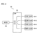
- Fig. 5 shows a related-art time synchronization system 101.
- the time synchronization system 101 includes a master 102, four slaves (a first slave 103-1 to a fourth slave 103-4 (generically referred to as a slave(s) 103), and a relay 104. Packet communications for purposes other than time synchronization are mainly performed between the master 102 and each slave 103, though packet communications for time synchronization are also performed.
- the relay 104 is a network relay for relaying communications between the master 102 and each slave 103 and is what is called a layer 2 switch (denoted by L2SW in Fig. 5 ) may be used as the relay 104.
- the relay 104 determines communication destinations based on IP addresses that are set in packets, and thereby realizes packet communications between the master 102 and the slaves 103.
- the relay 104 When packets are communicated from plural slaves 103 to the master 102, the relay 104 is loaded heavily because of concentration of packets. As shown in Fig. 6 , the layer 2 switch serving as the relay 104 has buffers 105 for respective IP addresses and sends out packets to the master 102 in order of their inputs to the buffers 105.
- Fig. 6 shows a state (first communication example) that ordinary packets (not for time synchronization) P1, P2, and P3 and a packet 1588 (for time synchronization) are being transmitted from the four slaves 103 to the master 102 via the relay 104.
- the ordinary packets P1-P3 and the time synchronization packet 1588 contain an IP address of the master 102 as a destination IP address.
- the time synchronization packet 1588 is given highest priority and hence is output first from the buffers 105 toward the master 102. Therefore, the time synchronization packet 1588 can be output with a shortest waiting time T1 without being affected by the other packets P1-P3.
- Fig. 7 shows a second communication example.
- time synchronization packet 1588 is given highest priority
- an ordinary packet P1 reached the buffers 105 before the time synchronization packet 1588 and is already being output from the buffers 105. Since the output of the ordinary packet P1 cannot be suspended halfway, the time synchronization packet 1588 should wait until completion of the output of the ordinary packet P1.
- the time synchronization packet 1588 is output after a lapse of a waiting time T2.
- Fig. 8 shows a third communication example.
- ordinary packets P1-P3 are higher in priority than a time synchronization packet 1588.
- the time synchronization packet 1588 is sent to the master 102 after completion of sending of the ordinary packets P1-P3.
- the time synchronization packet 1588 is sent to the master 102 after a lapse of a longest waiting time T3.
- a time synchronization packet is a packet for establishing time synchronization between the master 102 and each slave 103, and time synchronization cannot be established accurately if the timing of arrival of a time synchronization packet varies. That is, the accuracy of time synchronization deteriorates if the network delay from sending of a time synchronization packet by a slave 103 to its reception by the master 102 varies.
- the network delay can be made equal to the shortest waiting time T1. Since the waiting time T1 is not affected by the other ordinary packets P1-P3, the master 102 can establish time synchronization accurately based on the received time synchronization packet 1588.
- the waiting time T2 measures a maximum of 80 ⁇ s.
- the waiting time T2 varies up to 80 ⁇ s depending on the size of the ordinary packet P1 and to what extent its output has progressed. Thus, the waiting time T2 cannot be predicted.
- the time synchronization packet 1588 is output after completion of output of the ordinary packets P1-P3.
- the packet lengths of the ordinary packets P1-P3 are variable, and it cannot be predicted to what extent the output of the ordinary packets P1-P3 has progressed. Therefore, the waiting time T3 varies to a large extent.
- the master 102 and each slave 103 establish time synchronization based on a time synchronization packet. Therefore, if the waiting time varies as in the examples of Figs. 7 and 8 , the network delay varies and the accuracy of time synchronization deteriorates. In particular, packets are communicated from many slaves 103 to the master 102, the network delay varies to a large extent because of the concentration of packets.
- One or more illustrative aspects of the present invention are to increase the accuracy of time synchronization by reducing the variation of the network delay even at the occurrence of packet concentration.
- a time synchronization system comprises: a master comprising: a main processor to which a first IP address is assigned; and a time synchronization processor to which a second IP address is assigned, wherein the first IP address is different from the second IP address; a plurality of slaves configured to send a first packet whose destination is the first IP address and a second packet whose destination is the second IP address to the master, wherein the second packet is a packet for time synchronization between the master and one of the slaves, and the first packet is a data packet different from the second packet; and a relay provided between the slaves and the master to relay the first packet and the second packet sent from the slaves to the master, the relay being configured to send the first packet to the main processor and to send the second packet to the time synchronization processor.
- the main processor is configured to receive the first packet from the relay and perform a certain process on the first packet.
- the time synchronization processor is configured to receive the second packet from the relay and perform a time synchronization process between the master and said one of the slaves based on the second packet.
- the system further comprises a plurality of field devices each configured to measure or control a physical quantity of an object and communicating with the slaves to send a measurement data or control data of the physical quantity of the object to the slaves, wherein the first packet is the measurement data or control data of the physical quantity of the object.
- the field devices are configured to communicate with the slaves through a wireless communication.
- the field devices are configured to communicate with the slaves through the wireless communication using a time division multiplex communication.
- the field devices are configured to dynamically select a slave having a high communication quality from the plurality of slaves and communicate with the selected slave.
- each of the slaves has an internal clock. After the internal clocks of the slaves are synchronized with each other, the field devices communicate with the slaves through the wireless communication using a time division multiplex communication.
- the plurality of slaves are configured to measure or control a physical quantity of an object, wherein the first packet is a measurement data or control data of the physical quantity of the object.
- the time synchronization processor is removable from the master.
- the variation of the network delay is reduced and a time synchronization packet can be communicated without being affected by a variation of the network delay. Therefore, accurate time synchronization can be realized between the master and each slave.
- each slave is an apparatus which communicates with a physical quantity measurement and control device which measures a physical quantity
- the master is an apparatus which processes measurement data and controls the physical quantity measurement and control device by communicating with the slave.
- the master and the slave are not limited to these kinds of apparatus.
- the invention can also be applied to a system which is used in a substation and employs a time server, a system in which plural video cameras are connected using the IEEE 1588 protocol, and a time synchronization system in a home AV (Audio Video) LAN (Local Area Network).
- physical quantity measurement and control devices are field devices such as a pressure meter, a thermometer, a flow meter, etc. which measure a physical quantity such as pressure, temperature, or a flow rate and actuators such as a compressor, a heater, and a valve which control a physical quantity such as pressure, temperature, or a flow rate to a target value.
- Each physical quantity measurement and control device (hereinafter called a field device) is configured to communicate with the slave by wire or wirelessly and sends a measured physical quantity value to a slave as measurement data.
- Each slave sends received measurement data to the master which is located at a distant place.
- the master is configured to communicate with one or plural slaves over a network by wire or wirelessly. The master performs prescribed processing on measurement data received from each slave.
- the master sends control data for controlling the field devices to the slaves over the network.
- the control data are received by the slaves, and the slaves control the field devices by sending control data to them.
- the master and each slave incorporate an internal clock therein, and it is important to establish time synchronization between the master and each slave.
- a field device performs a measurement with prescribed timing and sends measurement data to a slave.
- the slave sends the received measurement data to the master, and the master makes a comparison using the received measurement data and determines whether or not the physical quantity value is normal. In this operation, it is very important that time synchronization be established between the master and the slave.
- time synchronization packets are communicated in a constant cycle.
- time synchronization packets may be affected by high concentration of packets of measurement data, resulting in deterioration in the accuracy of time synchronization. If the accuracy of time synchronization of the slaves is deteriorated, each field device cannot measure a measurement subject with the same timing, resulting in a serious reduction in measurement accuracy.
- Fig. 1 shows a time synchronization system 1 according to the embodiment, which has a master 2 and four slaves (a first slave 3-1 to a fourth slave 3-4 (generically referred to as a slave(s) 3)), a relay 4, and four field devices (a first field device 5-1 to a fourth field device 5-2 (generically referred to as a field device(s) 5).
- the number of slaves 3 is not limited to four and may be any arbitrary plural number.
- the number of field devices 5 is not limited to four and may be any arbitrary plural number.
- each slave 3 communicates with one field device 5, a slave(s) may exist which communicates with plural field devices 5.
- Each slave 3 and the corresponding field device 5 may communicate with each other either by wire or wirelessly. In this example, it is assumed that each slave 3 and the corresponding field device 5 communicate with each other wirelessly.
- the master 2 and each slave 3 may communicate with each other either by wire or wirelessly. In this example, it is assumed that the master 2 and each slave 3 communicate with each other by wire. Therefore, the master 2 and the relay 4 are connected to each other by wire and the relay 4 and each slave 3 are connected to each other by wire.
- the master 2 is a host apparatus. Each slave 3 communicates with the corresponding field device 5. Thus, each slave 3 receives measurement data measured by the corresponding field device 5 and sends the received measurement data to the master by a packet communication. Control data is sent from the master 2 to each slave 3 by a packet communication, which communicates the received control data to the corresponding field device 5. In this manner, the master 2 controls the individual field devices 5.
- the master 2 and the individual slaves 3 are connected by a network and the relay 4 is provided in the network.
- the relay 4 is a layer 2 switch (denoted by L2SW in Fig. 1 ).
- the master 2 has a main processor 10 and a time synchronization processor 11.
- the main processor 10 is configured to perform processing other than time synchronization; it mainly processes measurement data. Therefore, the main processor 10 employs a CPU having a high processing ability.
- the time synchronization processor 11 is a processor that is dedicated to time synchronization, and may employ either a CPU or a circuit for performing time synchronization processing. Where the time synchronization processor 11 may employ a CPU having a low processing ability because it is required to perform only time synchronization processing.
- the two functions of the main processor and the time synchronization processor are implemented by using one CPU and one network port. That is, ordinary masters employ a CPU having the two functions of the main processor and the time synchronization processor, and perform both of measurement data processing and time synchronization processing.
- the master 2 separately employs the CPU provided in the main processor 10 and the CPU (or processing circuit) provided in the time synchronization processor 11.
- the master 2 may employ a device in which a single CPU has plural network ports.
- the main processor 10 and the time synchronization processor 11 are assigned different IP addresses.
- discrimination can be made between a packet (ordinary packet) to be supplied to the main processor 10 and a packet (time synchronization packet) to be supplied to the time synchronization processor 11.
- a packet can be supplied to the main processor 10 or the time synchronization processor 11 that corresponds to the destination IP address contained in the packet.
- Fig. 2 shows the details of the relay 4.
- the relay 4 includes a selector 21, a first buffer 22, and a second buffer 23.
- the selector 21 is configured to distribute packets transmitted from the slaves 3 to destinations that are indicated by respective destination IP addresses contained therein.
- solid-line arrows coming out of the selector 21 indicate that packets are supplied to the first buffer 22 and broken-line arrows indicate that packets are supplied to the second buffer 23.
- the first buffer 22 and the second buffer 23 are transmission buffers provided for the respective IP addresses. That is, the first buffer 22 is a buffer corresponding to the IP address of the main processor 10 and the second buffer 23 is a buffer corresponding to the IP address of the time synchronization processor 11. Naturally, the number of IP addresses is not limited to two and may be three or more. Also in the latter case, the selector 21 distributes packets to destinations that are indicated by respective destination IP addresses contained therein.
- number of IP addresses as used herein means a logical number; physically, the functions of plural buffers can be realized by dividing the storage area of a single memory.
- the relay 4 is not limited to a layer 2 switch and may be an arbitrary kind of relay as long as it has the selector 21, the first buffer 22, and the second buffer 23.
- Fig. 2 shows a first communication example. Measurement data are communicated wirelessly from the first field device 5-1 to the fourth field device 5-4 to the first slave 3-1 to the fourth slave 3-4. It is assumed that the first slave 3-1 to the fourth slave 3-4 output packets almost simultaneously. It is also assumed that the first slave 3-1 to the third slave 3-3 output respective ordinary packets P1-P3 and the fourth slave 3-4 outputs a time synchronization packet 1588. This causes high packet concentration in the relay 4.
- the selector 21 stores the ordinary packets P1-P3 in the first buffer 22 in order.
- the packet P1 which is stored at the head of the first buffer 22 is first sent to the main processor 10.
- the selector 21 stores the time synchronization packet 1588 in the second buffer 23.
- the time synchronization packet 1588 which is stored in the second buffer 23 is sent to the time synchronization processor 11 with a shortest waiting time T1.
- the time synchronization packet 1588 which is stored in the second buffer 23 is not affected by the other, ordinary packets P1-P3, because the main processor 10 and the time synchronization processor 11 are assigned different IP addresses and the selector 21 distributes the packets to destinations that are indicated by respective IP addresses contained therein.
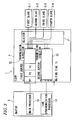
- Fig. 3 shows a second communication example, and shows a state that ordinary packets P1-P3 transmitted from the first slave 3-1 to the third slave 3-3 are stored in the first buffer 22 according to destination IP addresses (the IP address of the main processor 10) contained therein.
- the head packet P1 is being output from the first buffer 22.
- a time synchronization packet 1588 transmitted from the fourth slave 3-4 has, as a destination IP address, the IP address of the time synchronization processor 11, it is sent to the time synchronization processor 11 from the second buffer 23.
- the time synchronization packet 1588 is not affected by the other, ordinary packets P1-P3.
- the time synchronization packet 1588 can be sent to the time synchronization processor 11 without waiting for completion of the output of the ordinary packet P1. As a result, the time synchronization packet 1588 can be sent to the time synchronization processor 11 with the shortest waiting time T1.
- Fig. 4 shows a third communication example, and shows a state that ordinary packets P1-P3 transmitted from the first slave 3-1 to the third slave 3-3 are stored in the first buffer 22 according to destination IP addresses (the IP address of the main processor 10) contained therein. It is assumed that the ordinary packets P1-P3 are higher in priority than time synchronization packets. Therefore, if a time synchronization packet were stored in the first buffer 22, it would be stored in the last place.
- the fourth slave 3-4 designated the IP address of the time synchronization processor 11 as the destination address of a time synchronization packet 1588
- the time synchronization packet 1588 is stored in the second buffer 23. Therefore, the time synchronization packet 1588 can be sent to the time synchronization processor 11 with the shortest waiting time T1 ( Fig. 4 ends up being identical to Fig. 2 ).
- the time synchronization packet 1588 that has been transmitted from the fourth slave 3-4 can be sent to the time synchronization processor 11 with the shortest waiting time T1. That is, the time synchronization packet 1588 can always be sent to the time synchronization processor 11 with the same (fixed), shortest waiting time T1 without being affected by the other, ordinary packets P1-P3.
- the time (network delay) from output of a time synchronization packet from a slave 3 to its input to the master 2 is always kept at a fixed value and does not vary. This increases the accuracy of time synchronization. Furthermore, synchronization packets are transmitted in a constant cycle from the slaves 3 to the master 2, they are less prone to be delayed. Thus, time synchronization between the master 2 and each slave 3 can be performed with the shortest waiting time.
- the variation of the network delay can be suppressed and the accuracy of time synchronization can be increased by dividing the master 2 into the two systems, that is, the system of the main processor 10 and the system of the time synchronization processor 11, and dedicating the latter to time synchronization.
- the separate CPUs are used in the main processor 10 and the time synchronization processor 11.
- the CPU of the main processor 10 is required to have a high computing ability because it needs to perform computation such as calculation using measurement data. There are few CPU options which have a high computing ability and can perform time synchronization processing.
- the CPU used in the main processor 10 can be a one that specializes in a high computing ability, whereby a wide range of CPU options are available. Since the CPU used in the time synchronization processor 11 can be a one that specializes in time synchronization, it is not required to have a high processing ability. A wide range of CPU options are also available for the CPU used in the time synchronization processor 11.
- the main processor 10 and the time synchronization processor 11 were implemented using a single CPU, the CPU should have a high processing ability and be capable of performing time synchronization processing. Only a narrow range of options would be available for such a CPU, and such a CPU would be expensive. In the embodiment, since the separate CPUs are used in the main processor 10 and the time synchronization processor 11, it is not necessary to use an expensive CPU, which enables cost reduction.
- time synchronization processor 11 can be removed from the master 2, the synchronization processor 11 removed from the master 2 can be incorporated into another master. Such installation of the time synchronization processor 11 makes it possible to apply the concept of the embodiment to another type of system.
- the slaves 3 are connected to the master 2 via the single relay 4, there may be a case that the slaves 3 are connected to the master 2 via plural relay 4. In such a case, the plural relay 4 are connected by two systems and one of the two systems is dedicated to time synchronization packets.
- the master 2 and the relay 4 are separate apparatus, they may be implemented as integral hardware.
- time synchronization system 1 is configured in such a manner that each slave 3 wirelessly communicates with one (or plural) field device 5
- a time synchronization system may be configured in such a manner that each field device 5 wirelessly communicates with plural slaves 3.
- a field device 5 may exist which can communicate with plural slaves 3 wirelessly.
- the radio wave transmission state such as the radio wave intensity
- the wireless communication path may be switched dynamically using a slave 3 that provides a good radio wave transmission state.
- dynamic switching is made between plural slaves 3, it is necessary that the slaves 3 are synchronized with each other. This measure makes it possible to realize good wireless communications between the slaves 3 and the field devices 5.
- each slave 3 wirelessly communicates with one (or plural) field device 5
- slaves 3 themselves may function as field devices 5, that is, physical quantity measurement and control devices. That is, each slave 3 may measure a physical quantity value and communicate measurement data to the master 2.
- the master 2 can control measurement by each slave 3 by sending control data to it.
Landscapes
- Engineering & Computer Science (AREA)
- Computer Networks & Wireless Communication (AREA)
- Signal Processing (AREA)
- Computer Security & Cryptography (AREA)
- Synchronisation In Digital Transmission Systems (AREA)
- Small-Scale Networks (AREA)
- Mobile Radio Communication Systems (AREA)
- Electric Clocks (AREA)
Abstract
Description
- Embodiments described herein relate to a time synchronization system for communication between a master and plural slaves.
- Systems are known in which a master and plural slaves are connected by a network and data communications are performed between them over the network. Each of the master and the slaves incorporates an internal clock therein, and it is important to establish synchronization between the master and each slave. The IEEE 1588 protocol (hereinafter referred to as "1588 protocol") is known as a protocol for such time synchronization.
- In the 1588 protocol, the internal clocks of the master and each slave are synchronized with each other by exchanging packets which contain time stamp information generated based on the internal clock of each apparatus and calculating a network delay and a time difference.
JP-A-2010-4321 - In the 1588 protocol, in general, each slave sends, to the master, packets containing a transmission time that is calculated based on its own internal clock. The master determines a reception time based on its own internal clock. The difference between the transmission time and the reception time is equal to the sum of a time difference between the two internal clocks and a network delay. The same applies to a case that the master sends time synchronization packets to each slave. In this manner, the internal clocks of the master and each slave are synchronized with each other by calculating a time difference between the two internal clocks and a network delay.
-
Fig. 5 shows a related-arttime synchronization system 101. Thetime synchronization system 101 includes amaster 102, four slaves (a first slave 103-1 to a fourth slave 103-4 (generically referred to as a slave(s) 103), and arelay 104. Packet communications for purposes other than time synchronization are mainly performed between themaster 102 and each slave 103, though packet communications for time synchronization are also performed. - The
relay 104 is a network relay for relaying communications between themaster 102 and each slave 103 and is what is called alayer 2 switch (denoted by L2SW inFig. 5 ) may be used as therelay 104. Therelay 104 determines communication destinations based on IP addresses that are set in packets, and thereby realizes packet communications between themaster 102 and the slaves 103. - When packets are communicated from plural slaves 103 to the
master 102, therelay 104 is loaded heavily because of concentration of packets. As shown inFig. 6 , thelayer 2 switch serving as therelay 104 hasbuffers 105 for respective IP addresses and sends out packets to themaster 102 in order of their inputs to thebuffers 105. -
Fig. 6 shows a state (first communication example) that ordinary packets (not for time synchronization) P1, P2, and P3 and a packet 1588 (for time synchronization) are being transmitted from the four slaves 103 to themaster 102 via therelay 104. The ordinary packets P1-P3 and the time synchronization packet 1588 contain an IP address of themaster 102 as a destination IP address. - In the example of
Fig. 6 , the time synchronization packet 1588 is given highest priority and hence is output first from thebuffers 105 toward themaster 102. Therefore, the time synchronization packet 1588 can be output with a shortest waiting time T1 without being affected by the other packets P1-P3. -
Fig. 7 shows a second communication example. In this example, although time synchronization packet 1588 is given highest priority, an ordinary packet P1 reached thebuffers 105 before the time synchronization packet 1588 and is already being output from thebuffers 105. Since the output of the ordinary packet P1 cannot be suspended halfway, the time synchronization packet 1588 should wait until completion of the output of the ordinary packet P1. The time synchronization packet 1588 is output after a lapse of a waiting time T2. -
Fig. 8 shows a third communication example. In this example, ordinary packets P1-P3 are higher in priority than a time synchronization packet 1588. The time synchronization packet 1588 is sent to themaster 102 after completion of sending of the ordinary packets P1-P3. In this example, the time synchronization packet 1588 is sent to themaster 102 after a lapse of a longest waiting time T3. - A time synchronization packet is a packet for establishing time synchronization between the
master 102 and each slave 103, and time synchronization cannot be established accurately if the timing of arrival of a time synchronization packet varies. That is, the accuracy of time synchronization deteriorates if the network delay from sending of a time synchronization packet by a slave 103 to its reception by themaster 102 varies. - In the example of
Fig. 6 in which the time synchronization packet 1588 is output first, and thus is not affected by the other ordinary packets P1-P3. Hence, the network delay can be made equal to the shortest waiting time T1. Since the waiting time T1 is not affected by the other ordinary packets P1-P3, themaster 102 can establish time synchronization accurately based on the received time synchronization packet 1588. - On the other hand, in the example of
Fig. 7 in which output of the ordinary packet P1 has already started though the time synchronization packet 1588 is given highest priority. Output of the time synchronization packet 1588 is started after completion of the output of the ordinary packet P1. In this example, the waiting time T2 varies depending on to what extent the output of the ordinary packet P1 has progressed at the time of arrival of the time synchronization packet 1588 at therelay 104. - For example, where the communication rate is 100 Mbps and the packet length of the ordinary packet P1 is 1 Kbytes, the waiting time T2 measures a maximum of 80 µs. The waiting time T2 varies up to 80 µs depending on the size of the ordinary packet P1 and to what extent its output has progressed. Thus, the waiting time T2 cannot be predicted.
- In the example of
Fig. 8 in which the ordinary packets P1-P3 are higher in priority than the time synchronization packet 1588, the time synchronization packet 1588 is output after completion of output of the ordinary packets P1-P3. The packet lengths of the ordinary packets P1-P3 are variable, and it cannot be predicted to what extent the output of the ordinary packets P1-P3 has progressed. Therefore, the waiting time T3 varies to a large extent. - As mentioned above, the
master 102 and each slave 103 establish time synchronization based on a time synchronization packet. Therefore, if the waiting time varies as in the examples ofFigs. 7 and8 , the network delay varies and the accuracy of time synchronization deteriorates. In particular, packets are communicated from many slaves 103 to themaster 102, the network delay varies to a large extent because of the concentration of packets. - One or more illustrative aspects of the present invention are to increase the accuracy of time synchronization by reducing the variation of the network delay even at the occurrence of packet concentration.
- According to one or more aspects of the present invention, there is provided a time synchronization system. The time synchronization system comprises: a master comprising: a main processor to which a first IP address is assigned; and a time synchronization processor to which a second IP address is assigned, wherein the first IP address is different from the second IP address; a plurality of slaves configured to send a first packet whose destination is the first IP address and a second packet whose destination is the second IP address to the master, wherein the second packet is a packet for time synchronization between the master and one of the slaves, and the first packet is a data packet different from the second packet; and a relay provided between the slaves and the master to relay the first packet and the second packet sent from the slaves to the master, the relay being configured to send the first packet to the main processor and to send the second packet to the time synchronization processor. The main processor is configured to receive the first packet from the relay and perform a certain process on the first packet. The time synchronization processor is configured to receive the second packet from the relay and perform a time synchronization process between the master and said one of the slaves based on the second packet.
- According to one or more aspects of the present invention, the system further comprises a plurality of field devices each configured to measure or control a physical quantity of an object and communicating with the slaves to send a measurement data or control data of the physical quantity of the object to the slaves, wherein the first packet is the measurement data or control data of the physical quantity of the object.
- According to one or more aspects of the present invention, the field devices are configured to communicate with the slaves through a wireless communication.
- According to one or more aspects of the present invention, the field devices are configured to communicate with the slaves through the wireless communication using a time division multiplex communication.
- According to one or more aspects of the present invention, the field devices are configured to dynamically select a slave having a high communication quality from the plurality of slaves and communicate with the selected slave.
- According to one or more aspects of the present invention, each of the slaves has an internal clock. After the internal clocks of the slaves are synchronized with each other, the field devices communicate with the slaves through the wireless communication using a time division multiplex communication.
- According to one or more aspects of the present invention, the plurality of slaves are configured to measure or control a physical quantity of an object, wherein the first packet is a measurement data or control data of the physical quantity of the object.
- According to one or more aspects of the present invention, the time synchronization processor is removable from the master.
- According to the present invention, the variation of the network delay is reduced and a time synchronization packet can be communicated without being affected by a variation of the network delay. Therefore, accurate time synchronization can be realized between the master and each slave.
- Other aspects and advantages of the present invention will be apparent from the following description, the drawings and the claims.
-
-
Fig. 1 outlines a time synchronization system according to an embodiment; -
Fig. 2 shows a first communication example in the time synchronization system according to the embodiment; -
Fig. 3 shows a second communication example in the time synchronization system according to the embodiment; -
Fig. 4 shows a third communication example in the time synchronization system according to the embodiment; -
Fig. 5 outlines a related-art time synchronization system; -
Fig. 6 shows a first communication example in the related-art conventional time synchronization system; -
Fig. 7 shows a second communication example in the related-art time synchronization system; and -
Fig. 8 shows a third communication example in the related-art time synchronization system. - An embodiment of the present invention will be hereinafter described with reference to the drawings. The following description will be made with assumptions that each slave is an apparatus which communicates with a physical quantity measurement and control device which measures a physical quantity, and the master is an apparatus which processes measurement data and controls the physical quantity measurement and control device by communicating with the slave. In this embodiment, the master and the slave are not limited to these kinds of apparatus. For example, the invention can also be applied to a system which is used in a substation and employs a time server, a system in which plural video cameras are connected using the IEEE 1588 protocol, and a time synchronization system in a home AV (Audio Video) LAN (Local Area Network).
- For example, physical quantity measurement and control devices are field devices such as a pressure meter, a thermometer, a flow meter, etc. which measure a physical quantity such as pressure, temperature, or a flow rate and actuators such as a compressor, a heater, and a valve which control a physical quantity such as pressure, temperature, or a flow rate to a target value.
- Each physical quantity measurement and control device (hereinafter called a field device) is configured to communicate with the slave by wire or wirelessly and sends a measured physical quantity value to a slave as measurement data. Each slave sends received measurement data to the master which is located at a distant place. The master is configured to communicate with one or plural slaves over a network by wire or wirelessly. The master performs prescribed processing on measurement data received from each slave.
- The master sends control data for controlling the field devices to the slaves over the network. The control data are received by the slaves, and the slaves control the field devices by sending control data to them.
- The master and each slave incorporate an internal clock therein, and it is important to establish time synchronization between the master and each slave. For example, a field device performs a measurement with prescribed timing and sends measurement data to a slave. The slave sends the received measurement data to the master, and the master makes a comparison using the received measurement data and determines whether or not the physical quantity value is normal. In this operation, it is very important that time synchronization be established between the master and the slave.
- In particular, since the slaves frequently send measurement data to the master, high packet concentration tends to occur. On the other hand, time synchronization packets are communicated in a constant cycle. As a result, time synchronization packets may be affected by high concentration of packets of measurement data, resulting in deterioration in the accuracy of time synchronization. If the accuracy of time synchronization of the slaves is deteriorated, each field device cannot measure a measurement subject with the same timing, resulting in a serious reduction in measurement accuracy.
-
Fig. 1 shows a time synchronization system 1 according to the embodiment, which has amaster 2 and four slaves (a first slave 3-1 to a fourth slave 3-4 (generically referred to as a slave(s) 3)), arelay 4, and four field devices (a first field device 5-1 to a fourth field device 5-2 (generically referred to as a field device(s) 5). - The number of
slaves 3 is not limited to four and may be any arbitrary plural number. Likewise, the number of field devices 5 is not limited to four and may be any arbitrary plural number. Although inFig. 1 eachslave 3 communicates with one field device 5, a slave(s) may exist which communicates with plural field devices 5. - Each
slave 3 and the corresponding field device 5 may communicate with each other either by wire or wirelessly. In this example, it is assumed that eachslave 3 and the corresponding field device 5 communicate with each other wirelessly. Themaster 2 and eachslave 3 may communicate with each other either by wire or wirelessly. In this example, it is assumed that themaster 2 and eachslave 3 communicate with each other by wire. Therefore, themaster 2 and therelay 4 are connected to each other by wire and therelay 4 and eachslave 3 are connected to each other by wire. - The
master 2 is a host apparatus. Eachslave 3 communicates with the corresponding field device 5. Thus, eachslave 3 receives measurement data measured by the corresponding field device 5 and sends the received measurement data to the master by a packet communication. Control data is sent from themaster 2 to eachslave 3 by a packet communication, which communicates the received control data to the corresponding field device 5. In this manner, themaster 2 controls the individual field devices 5. Themaster 2 and theindividual slaves 3 are connected by a network and therelay 4 is provided in the network. In this example, therelay 4 is alayer 2 switch (denoted by L2SW inFig. 1 ). - The
master 2 has amain processor 10 and atime synchronization processor 11. Themain processor 10 is configured to perform processing other than time synchronization; it mainly processes measurement data. Therefore, themain processor 10 employs a CPU having a high processing ability. Thetime synchronization processor 11 is a processor that is dedicated to time synchronization, and may employ either a CPU or a circuit for performing time synchronization processing. Where thetime synchronization processor 11 may employ a CPU having a low processing ability because it is required to perform only time synchronization processing. - In ordinary masters, the two functions of the main processor and the time synchronization processor are implemented by using one CPU and one network port. That is, ordinary masters employ a CPU having the two functions of the main processor and the time synchronization processor, and perform both of measurement data processing and time synchronization processing. On the other hand, in the embodiment, the
master 2 separately employs the CPU provided in themain processor 10 and the CPU (or processing circuit) provided in thetime synchronization processor 11. Alternatively, themaster 2 may employ a device in which a single CPU has plural network ports. - The
main processor 10 and thetime synchronization processor 11 are assigned different IP addresses. By virtue of this measure, in a packet communication from aslave 3, discrimination can be made between a packet (ordinary packet) to be supplied to themain processor 10 and a packet (time synchronization packet) to be supplied to thetime synchronization processor 11. Thus, a packet can be supplied to themain processor 10 or thetime synchronization processor 11 that corresponds to the destination IP address contained in the packet. -
Fig. 2 shows the details of therelay 4. Although the field devices 5 are not shown inFigs. 2-4 for the sake of convenience, also in the examples ofFigs. 2 to 4 eachslave 3 performs wireless communications with the corresponding field device 5. As shown inFig. 2 , therelay 4 includes aselector 21, afirst buffer 22, and asecond buffer 23. Theselector 21 is configured to distribute packets transmitted from theslaves 3 to destinations that are indicated by respective destination IP addresses contained therein. InFig. 2 , solid-line arrows coming out of theselector 21 indicate that packets are supplied to thefirst buffer 22 and broken-line arrows indicate that packets are supplied to thesecond buffer 23. - The
first buffer 22 and thesecond buffer 23 are transmission buffers provided for the respective IP addresses. That is, thefirst buffer 22 is a buffer corresponding to the IP address of themain processor 10 and thesecond buffer 23 is a buffer corresponding to the IP address of thetime synchronization processor 11. Naturally, the number of IP addresses is not limited to two and may be three or more. Also in the latter case, theselector 21 distributes packets to destinations that are indicated by respective destination IP addresses contained therein. The term "number of IP addresses" as used herein means a logical number; physically, the functions of plural buffers can be realized by dividing the storage area of a single memory. - Therefore, the
relay 4 is not limited to alayer 2 switch and may be an arbitrary kind of relay as long as it has theselector 21, thefirst buffer 22, and thesecond buffer 23. - Next, a description will be made of how the time synchronization system 1 operates.
Fig. 2 shows a first communication example. Measurement data are communicated wirelessly from the first field device 5-1 to the fourth field device 5-4 to the first slave 3-1 to the fourth slave 3-4. It is assumed that the first slave 3-1 to the fourth slave 3-4 output packets almost simultaneously. It is also assumed that the first slave 3-1 to the third slave 3-3 output respective ordinary packets P1-P3 and the fourth slave 3-4 outputs a time synchronization packet 1588. This causes high packet concentration in therelay 4. - Since the first slave 3-1 to the third slave 3-3 output the respective ordinary packets P1-P3, the destination IP addresses contained therein are the IP address of the
main processor 10. Therefore, theselector 21 stores the ordinary packets P1-P3 in thefirst buffer 22 in order. The packet P1 which is stored at the head of thefirst buffer 22 is first sent to themain processor 10. - On the other hand, since the fourth slave 3-4 outputs the time synchronization packet, the destination IP address contained therein is the IP address of the
time synchronization processor 11. Therefore, theselector 21 stores the time synchronization packet 1588 in thesecond buffer 23. The time synchronization packet 1588 which is stored in thesecond buffer 23 is sent to thetime synchronization processor 11 with a shortest waiting time T1. - The time synchronization packet 1588 which is stored in the
second buffer 23 is not affected by the other, ordinary packets P1-P3, because themain processor 10 and thetime synchronization processor 11 are assigned different IP addresses and theselector 21 distributes the packets to destinations that are indicated by respective IP addresses contained therein. -
Fig. 3 shows a second communication example, and shows a state that ordinary packets P1-P3 transmitted from the first slave 3-1 to the third slave 3-3 are stored in thefirst buffer 22 according to destination IP addresses (the IP address of the main processor 10) contained therein. The head packet P1 is being output from thefirst buffer 22. - On the other hand, since a time synchronization packet 1588 transmitted from the fourth slave 3-4 has, as a destination IP address, the IP address of the
time synchronization processor 11, it is sent to thetime synchronization processor 11 from thesecond buffer 23. The time synchronization packet 1588 is not affected by the other, ordinary packets P1-P3. - That is, even if output of the ordinary packet P1 has already started, the time synchronization packet 1588 can be sent to the
time synchronization processor 11 without waiting for completion of the output of the ordinary packet P1. As a result, the time synchronization packet 1588 can be sent to thetime synchronization processor 11 with the shortest waiting time T1. -
Fig. 4 shows a third communication example, and shows a state that ordinary packets P1-P3 transmitted from the first slave 3-1 to the third slave 3-3 are stored in thefirst buffer 22 according to destination IP addresses (the IP address of the main processor 10) contained therein. It is assumed that the ordinary packets P1-P3 are higher in priority than time synchronization packets. Therefore, if a time synchronization packet were stored in thefirst buffer 22, it would be stored in the last place. - However, as shown in
Fig. 4 , since the fourth slave 3-4 designated the IP address of thetime synchronization processor 11 as the destination address of a time synchronization packet 1588, the time synchronization packet 1588 is stored in thesecond buffer 23. Therefore, the time synchronization packet 1588 can be sent to thetime synchronization processor 11 with the shortest waiting time T1 (Fig. 4 ends up being identical toFig. 2 ). - In each of the examples of
Figs. 2-4 , the time synchronization packet 1588 that has been transmitted from the fourth slave 3-4 can be sent to thetime synchronization processor 11 with the shortest waiting time T1. That is, the time synchronization packet 1588 can always be sent to thetime synchronization processor 11 with the same (fixed), shortest waiting time T1 without being affected by the other, ordinary packets P1-P3. - As described above, the time (network delay) from output of a time synchronization packet from a
slave 3 to its input to themaster 2 is always kept at a fixed value and does not vary. This increases the accuracy of time synchronization. Furthermore, synchronization packets are transmitted in a constant cycle from theslaves 3 to themaster 2, they are less prone to be delayed. Thus, time synchronization between themaster 2 and eachslave 3 can be performed with the shortest waiting time. - As described above, the variation of the network delay can be suppressed and the accuracy of time synchronization can be increased by dividing the
master 2 into the two systems, that is, the system of themain processor 10 and the system of thetime synchronization processor 11, and dedicating the latter to time synchronization. - In the
master 2, the separate CPUs are used in themain processor 10 and thetime synchronization processor 11. The CPU of themain processor 10 is required to have a high computing ability because it needs to perform computation such as calculation using measurement data. There are few CPU options which have a high computing ability and can perform time synchronization processing. - In the embodiment, since the CPUs having the different functions are used in the
main processor 10 and thetime synchronization processor 11, respectively, the CPU used in themain processor 10 can be a one that specializes in a high computing ability, whereby a wide range of CPU options are available. Since the CPU used in thetime synchronization processor 11 can be a one that specializes in time synchronization, it is not required to have a high processing ability. A wide range of CPU options are also available for the CPU used in thetime synchronization processor 11. - Where the
main processor 10 and thetime synchronization processor 11 were implemented using a single CPU, the CPU should have a high processing ability and be capable of performing time synchronization processing. Only a narrow range of options would be available for such a CPU, and such a CPU would be expensive. In the embodiment, since the separate CPUs are used in themain processor 10 and thetime synchronization processor 11, it is not necessary to use an expensive CPU, which enables cost reduction. - If the
time synchronization processor 11 can be removed from themaster 2, thesynchronization processor 11 removed from themaster 2 can be incorporated into another master. Such installation of thetime synchronization processor 11 makes it possible to apply the concept of the embodiment to another type of system. - Although in the embodiment the
slaves 3 are connected to themaster 2 via thesingle relay 4, there may be a case that theslaves 3 are connected to themaster 2 viaplural relay 4. In such a case, theplural relay 4 are connected by two systems and one of the two systems is dedicated to time synchronization packets. - Although in the embodiment the
master 2 and therelay 4 are separate apparatus, they may be implemented as integral hardware. - Although the time synchronization system 1 according to the embodiment is configured in such a manner that each
slave 3 wirelessly communicates with one (or plural) field device 5, a time synchronization system may be configured in such a manner that each field device 5 wirelessly communicates withplural slaves 3. Depending on the positional relationships between theslaves 3 and the field devices 5, a field device 5 may exist which can communicate withplural slaves 3 wirelessly. - Depending on the installation environment of a field device 5, the radio wave transmission state (communication quality state) such as the radio wave intensity may vary. When the state of radio wave transmission between a field device 5 and a
slave 3 with which the field device 5 has communicated so far has degraded, the wireless communication path may be switched dynamically using aslave 3 that provides a good radio wave transmission state. When dynamic switching is made betweenplural slaves 3, it is necessary that theslaves 3 are synchronized with each other. This measure makes it possible to realize good wireless communications between theslaves 3 and the field devices 5. - Although in the embodiment each
slave 3 wirelessly communicates with one (or plural) field device 5,slaves 3 themselves may function as field devices 5, that is, physical quantity measurement and control devices. That is, eachslave 3 may measure a physical quantity value and communicate measurement data to themaster 2. In this case, themaster 2 can control measurement by eachslave 3 by sending control data to it.
Claims (8)
- A time synchronization system (1), comprising:a master (2) comprising:a main processor (10) to which a first IP address is assigned; anda time synchronization processor (11) to which a second IP address is assigned, wherein the first IP address is different from the second IP address;a plurality of slaves (3-1,3-2...) configured to send a first packet whose destination is the first IP address and a second packet whose destination is the second IP address to the master, wherein the second packet is a packet for time synchronization between the master and one of the slaves, and the first packet is a data packet different from the second packet; anda relay (4) provided between the slaves and the master to relay the first packet and the second packet sent from the slaves to the master, the relay being configured to send the first packet to the main processor and to send the second packet to the time synchronization processor, andwhereinthe main processor (10) is configured to receive the first packet from the relay and perform a certain process on the first packet; andthe time synchronization processor (11) is configured to receive the second packet from the relay and perform a time synchronization process between the master and said one of the slaves based on the second packet.
- The system of claim 1, further comprising:a plurality of field devices (5-1,5-2...) each configured to measure or control a physical quantity of an object and communicating with the slaves to send a measurement data or control data of the physical quantity of the object to the slaves, wherein the first packet is the measurement data or control data of the physical quantity of the object.
- The system of claim 2, wherein the field devices are configured to communicate with the slaves through a wireless communication.
- The system of claim 3, wherein the field devices are configured to communicate with the slaves through the wireless communication using a time division multiplex communication.
- The system of claim 3,
wherein the field devices are configured to dynamically select a slave having a high communication quality from the plurality of slaves and communicate with the selected slave. - The system of claim 3,
wherein each of the slaves has an internal clock,
after the internal clocks of the slaves are synchronized with each other, the field devices communicate with the slaves through the wireless communication using a time division multiplex communication. - The system of claim 1, wherein
the plurality of slaves are configured to measure or control a physical quantity of an object, wherein the first packet is a measurement data or control data of the physical quantity of the object. - The system of claim 7, wherein the time synchronization processor is removable from the master.
Applications Claiming Priority (1)
| Application Number | Priority Date | Filing Date | Title |
|---|---|---|---|
| JP2012004236A JP5459628B2 (en) | 2012-01-12 | 2012-01-12 | Time synchronization system |
Publications (3)
| Publication Number | Publication Date |
|---|---|
| EP2615753A2 true EP2615753A2 (en) | 2013-07-17 |
| EP2615753A3 EP2615753A3 (en) | 2017-06-07 |
| EP2615753B1 EP2615753B1 (en) | 2018-03-21 |
Family
ID=47561374
Family Applications (1)
| Application Number | Title | Priority Date | Filing Date |
|---|---|---|---|
| EP13151087.7A Active EP2615753B1 (en) | 2012-01-12 | 2013-01-11 | Time synchronization system |
Country Status (4)
| Country | Link |
|---|---|
| US (1) | US8943161B2 (en) |
| EP (1) | EP2615753B1 (en) |
| JP (1) | JP5459628B2 (en) |
| CN (1) | CN103209042B (en) |
Families Citing this family (20)
| Publication number | Priority date | Publication date | Assignee | Title |
|---|---|---|---|---|
| US9697159B2 (en) * | 2011-12-27 | 2017-07-04 | Intel Corporation | Multi-protocol I/O interconnect time synchronization |
| CN104767633B (en) * | 2014-01-07 | 2018-09-25 | 维谛技术有限公司 | A kind of Industrial Ethernet system |
| CN103929263B (en) * | 2014-04-30 | 2016-10-26 | 北京华力创通科技股份有限公司 | Network communication method |
| JP6516215B2 (en) * | 2015-03-25 | 2019-05-22 | セイコーソリューションズ株式会社 | Synchronization message transmitter, time synchronization system, synchronization message transmission method and program |
| JP6516217B2 (en) * | 2015-03-25 | 2019-05-22 | セイコーソリューションズ株式会社 | Synchronization message transmitter, time synchronization system, synchronization message transmission method and program |
| JP6516216B2 (en) * | 2015-03-25 | 2019-05-22 | セイコーソリューションズ株式会社 | Synchronization message transmitter, time synchronization system, synchronization message transmission method and program |
| EP3723421A1 (en) * | 2017-07-01 | 2020-10-14 | Ruckus Wireless, Inc. | Identifying a synchronization master for radio nodes |
| CN108259805B (en) * | 2018-03-30 | 2020-11-10 | 深圳市华宝电子科技有限公司 | Multi-channel video decoding method, playing method and device and automobile data recorder |
| DE112018007914B4 (en) * | 2018-09-21 | 2022-08-18 | Mitsubishi Electric Corporation | COMMUNICATION DEVICE, COMMUNICATION SYSTEM, COMMUNICATION METHOD AND COMMUNICATION PROGRAM |
| US11259058B2 (en) * | 2019-03-25 | 2022-02-22 | Apple Inc. | Use of rendered media to assess delays in media distribution systems |
| JP7322693B2 (en) * | 2019-12-20 | 2023-08-08 | 株式会社デンソー | Network system and control device |
| CN111131489A (en) * | 2019-12-30 | 2020-05-08 | 深圳市英威腾电气股份有限公司 | Data transmission method, device and storage medium |
| CN112422223B (en) * | 2020-11-06 | 2022-06-03 | 华能新能源股份有限公司河北分公司 | TCP/IP-based time synchronization device, time synchronization method and time mark monitoring system |
| JP7625962B2 (en) * | 2021-04-30 | 2025-02-04 | 株式会社オートネットワーク技術研究所 | On-vehicle device, on-vehicle network system, and information processing method |
| CN115314605A (en) * | 2021-05-06 | 2022-11-08 | 浙江宇视科技有限公司 | Method, device and equipment for realizing synchronization of camera shutter |
| JP7410085B2 (en) * | 2021-06-11 | 2024-01-09 | 矢崎総業株式会社 | Communication system and upper control device |
| US11831943B2 (en) * | 2021-10-26 | 2023-11-28 | Apple Inc. | Synchronized playback of media content |
| US11785285B1 (en) * | 2022-05-20 | 2023-10-10 | Lenbrook Industries Limited | Audio video receiver (AVR) architecture |
| CN115801884B (en) * | 2022-09-22 | 2025-06-20 | 国网河北省电力有限公司经济技术研究院 | Communication network master and slave station data connection method |
| US12205257B2 (en) * | 2023-04-21 | 2025-01-21 | Lenovo (Singapore) Pte. Ltd. | Method and device for reducing image noise |
Citations (1)
| Publication number | Priority date | Publication date | Assignee | Title |
|---|---|---|---|---|
| JP2010004321A (en) | 2008-06-20 | 2010-01-07 | Fujitsu Ltd | Time tracking system and time tracking apparatus |
Family Cites Families (14)
| Publication number | Priority date | Publication date | Assignee | Title |
|---|---|---|---|---|
| CA2406438C (en) * | 2000-04-07 | 2006-10-17 | Interdigital Technology Corporation | Base station synchronization for wireless communication systems |
| CH704101B1 (en) * | 2002-11-06 | 2012-05-31 | Barix Ag | Method and apparatus for synchronized playback of data streams. |
| EP1760563B1 (en) * | 2005-08-31 | 2009-10-14 | Omron Corporation | Communication system with master, slave and repeater units |
| JP4629639B2 (en) * | 2006-09-29 | 2011-02-09 | 富士通株式会社 | Packet relay device |
| JP2008109534A (en) * | 2006-10-27 | 2008-05-08 | Renesas Technology Corp | Packet relay device, and semiconductor chip |
| JP4558095B2 (en) * | 2007-04-04 | 2010-10-06 | 三菱電機株式会社 | COMMUNICATION SYSTEM, MANAGEMENT DEVICE, COMMUNICATION DEVICE, AND COMPUTER PROGRAM |
| CN100566300C (en) * | 2007-07-06 | 2009-12-02 | 中国科学院沈阳计算技术研究所有限公司 | A kind of netted trunking method and IP communication system of controlling the media delivery path |
| JP5045939B2 (en) * | 2008-03-28 | 2012-10-10 | サクサ株式会社 | Communication device and relay device |
| US8274998B2 (en) * | 2008-10-02 | 2012-09-25 | Cortina Systems, Inc. | Systems and methods for packet based timing offset determination using timing adjustment information |
| TWI510042B (en) * | 2008-12-15 | 2015-11-21 | Ind Tech Res Inst | Method and apparatus for packet encryption and decryption of precise time synchronization protocol and time synchronization system thereof |
| US8576883B2 (en) * | 2009-08-25 | 2013-11-05 | Semtech Corporation | Measurement and adjustment of real-time values according to residence time in networking equipment without access to real time |
| US8462821B1 (en) * | 2011-02-18 | 2013-06-11 | Juniper Networks, Inc. | Precision timing using a modified synchronization operation |
| SI2734904T1 (en) * | 2011-07-20 | 2018-05-31 | Aviat Networks, Inc. | Systems and methods of network synchronization |
| US8644350B2 (en) * | 2011-11-23 | 2014-02-04 | Vitesse Semiconductor Corporation | Packet-based timing measurement |
-
2012
- 2012-01-12 JP JP2012004236A patent/JP5459628B2/en active Active
-
2013
- 2013-01-10 US US13/738,285 patent/US8943161B2/en active Active
- 2013-01-11 EP EP13151087.7A patent/EP2615753B1/en active Active
- 2013-01-11 CN CN201310011199.3A patent/CN103209042B/en active Active
Patent Citations (1)
| Publication number | Priority date | Publication date | Assignee | Title |
|---|---|---|---|---|
| JP2010004321A (en) | 2008-06-20 | 2010-01-07 | Fujitsu Ltd | Time tracking system and time tracking apparatus |
Also Published As
| Publication number | Publication date |
|---|---|
| CN103209042A (en) | 2013-07-17 |
| JP2013143748A (en) | 2013-07-22 |
| EP2615753A3 (en) | 2017-06-07 |
| EP2615753B1 (en) | 2018-03-21 |
| US20130185374A1 (en) | 2013-07-18 |
| US8943161B2 (en) | 2015-01-27 |
| CN103209042B (en) | 2015-10-28 |
| JP5459628B2 (en) | 2014-04-02 |
Similar Documents
| Publication | Publication Date | Title |
|---|---|---|
| EP2615753B1 (en) | Time synchronization system | |
| CN108282415B (en) | Scheduling method and device | |
| EP2684321B1 (en) | Data blocking system for networks | |
| US8068429B2 (en) | Transmit scheduling | |
| US10802999B2 (en) | Industrial device communication system, communication method, and industrial device | |
| EP2817921B1 (en) | Network devices with time aware medium access controller | |
| JP7393530B2 (en) | Packet forwarding methods, devices, and systems | |
| KR101259230B1 (en) | Link band estimating apparatus and link band estimating method | |
| CN108353036B (en) | Packet Processing Technology for Communication Networks | |
| US7017067B2 (en) | Method and bus system for synchronizing a data exchange between a data source and a control device | |
| US9001841B2 (en) | Communication control device, parallel computer system, and communication control method | |
| US9665514B2 (en) | Integrated circuit having a bus network, and method for the integrated circuit | |
| CN119631362A (en) | Synchronous data network system and method for initializing and synchronizing the same | |
| US9385961B2 (en) | Parallel computing device, communication control device, and communication control method | |
| WO2023087588A1 (en) | Sampling circuit, use method of sampling circuit, storage medium, and electronic device | |
| CN101981908B (en) | Monitoring system | |
| US9342473B2 (en) | Parallel computer system, crossbar switch, and method of controlling parallel computer system according to selective transmission of data via ports of the crossbar switch | |
| US20220086778A1 (en) | Electronic apparatus, system, and method | |
| CN117319163A (en) | Business data transmission methods, equipment, electronic equipment and storage media | |
| CN116455833B (en) | EtherCAT network and link expansion method and device thereof | |
| US9473597B2 (en) | Implementing multiple MAC protocols using a single wireless communication unit | |
| CN116418756A (en) | Data stream transmission method, device, storage medium and electronic device | |
| CN103685365A (en) | Media access control implementation method |
Legal Events
| Date | Code | Title | Description |
|---|---|---|---|
| PUAI | Public reference made under article 153(3) epc to a published international application that has entered the european phase |
Free format text: ORIGINAL CODE: 0009012 |
|
| AK | Designated contracting states |
Kind code of ref document: A2 Designated state(s): AL AT BE BG CH CY CZ DE DK EE ES FI FR GB GR HR HU IE IS IT LI LT LU LV MC MK MT NL NO PL PT RO RS SE SI SK SM TR |
|
| AX | Request for extension of the european patent |
Extension state: BA ME |
|
| AK | Designated contracting states |
Kind code of ref document: A3 Designated state(s): AL AT BE BG CH CY CZ DE DK EE ES FI FR GB GR HR HU IE IS IT LI LT LU LV MC MK MT NL NO PL PT RO RS SE SI SK SM TR |
|
| AX | Request for extension of the european patent |
Extension state: BA ME |
|
| RIC1 | Information provided on ipc code assigned before grant |
Ipc: H04J 3/06 20060101AFI20170503BHEP |
|
| PUAL | Search report despatched |
Free format text: ORIGINAL CODE: 0009013 |
|
| STAA | Information on the status of an ep patent application or granted ep patent |
Free format text: STATUS: REQUEST FOR EXAMINATION WAS MADE |
|
| 17P | Request for examination filed |
Effective date: 20170717 |
|
| RBV | Designated contracting states (corrected) |
Designated state(s): AL AT BE BG CH CY CZ DE DK EE ES FI FR GB GR HR HU IE IS IT LI LT LU LV MC MK MT NL NO PL PT RO RS SE SI SK SM TR |
|
| GRAP | Despatch of communication of intention to grant a patent |
Free format text: ORIGINAL CODE: EPIDOSNIGR1 |
|
| STAA | Information on the status of an ep patent application or granted ep patent |
Free format text: STATUS: GRANT OF PATENT IS INTENDED |
|
| INTG | Intention to grant announced |
Effective date: 20170929 |
|
| GRAS | Grant fee paid |
Free format text: ORIGINAL CODE: EPIDOSNIGR3 |
|
| GRAA | (expected) grant |
Free format text: ORIGINAL CODE: 0009210 |
|
| STAA | Information on the status of an ep patent application or granted ep patent |
Free format text: STATUS: THE PATENT HAS BEEN GRANTED |
|
| AK | Designated contracting states |
Kind code of ref document: B1 Designated state(s): AL AT BE BG CH CY CZ DE DK EE ES FI FR GB GR HR HU IE IS IT LI LT LU LV MC MK MT NL NO PL PT RO RS SE SI SK SM TR |
|
| REG | Reference to a national code |
Ref country code: GB Ref legal event code: FG4D |
|
| REG | Reference to a national code |
Ref country code: CH Ref legal event code: EP |
|
| REG | Reference to a national code |
Ref country code: AT Ref legal event code: REF Ref document number: 982180 Country of ref document: AT Kind code of ref document: T Effective date: 20180415 |
|
| REG | Reference to a national code |
Ref country code: IE Ref legal event code: FG4D |
|
| REG | Reference to a national code |
Ref country code: DE Ref legal event code: R096 Ref document number: 602013034592 Country of ref document: DE |
|
| REG | Reference to a national code |
Ref country code: NL Ref legal event code: MP Effective date: 20180321 |
|
| PG25 | Lapsed in a contracting state [announced via postgrant information from national office to epo] |
Ref country code: LT Free format text: LAPSE BECAUSE OF FAILURE TO SUBMIT A TRANSLATION OF THE DESCRIPTION OR TO PAY THE FEE WITHIN THE PRESCRIBED TIME-LIMIT Effective date: 20180321 Ref country code: CY Free format text: LAPSE BECAUSE OF FAILURE TO SUBMIT A TRANSLATION OF THE DESCRIPTION OR TO PAY THE FEE WITHIN THE PRESCRIBED TIME-LIMIT Effective date: 20180321 Ref country code: NO Free format text: LAPSE BECAUSE OF FAILURE TO SUBMIT A TRANSLATION OF THE DESCRIPTION OR TO PAY THE FEE WITHIN THE PRESCRIBED TIME-LIMIT Effective date: 20180621 Ref country code: HR Free format text: LAPSE BECAUSE OF FAILURE TO SUBMIT A TRANSLATION OF THE DESCRIPTION OR TO PAY THE FEE WITHIN THE PRESCRIBED TIME-LIMIT Effective date: 20180321 Ref country code: FI Free format text: LAPSE BECAUSE OF FAILURE TO SUBMIT A TRANSLATION OF THE DESCRIPTION OR TO PAY THE FEE WITHIN THE PRESCRIBED TIME-LIMIT Effective date: 20180321 |
|
| REG | Reference to a national code |
Ref country code: LT Ref legal event code: MG4D |
|
| REG | Reference to a national code |
Ref country code: AT Ref legal event code: MK05 Ref document number: 982180 Country of ref document: AT Kind code of ref document: T Effective date: 20180321 |
|
| PG25 | Lapsed in a contracting state [announced via postgrant information from national office to epo] |
Ref country code: RS Free format text: LAPSE BECAUSE OF FAILURE TO SUBMIT A TRANSLATION OF THE DESCRIPTION OR TO PAY THE FEE WITHIN THE PRESCRIBED TIME-LIMIT Effective date: 20180321 Ref country code: GR Free format text: LAPSE BECAUSE OF FAILURE TO SUBMIT A TRANSLATION OF THE DESCRIPTION OR TO PAY THE FEE WITHIN THE PRESCRIBED TIME-LIMIT Effective date: 20180622 Ref country code: LV Free format text: LAPSE BECAUSE OF FAILURE TO SUBMIT A TRANSLATION OF THE DESCRIPTION OR TO PAY THE FEE WITHIN THE PRESCRIBED TIME-LIMIT Effective date: 20180321 Ref country code: BG Free format text: LAPSE BECAUSE OF FAILURE TO SUBMIT A TRANSLATION OF THE DESCRIPTION OR TO PAY THE FEE WITHIN THE PRESCRIBED TIME-LIMIT Effective date: 20180621 Ref country code: SE Free format text: LAPSE BECAUSE OF FAILURE TO SUBMIT A TRANSLATION OF THE DESCRIPTION OR TO PAY THE FEE WITHIN THE PRESCRIBED TIME-LIMIT Effective date: 20180321 |
|
| PG25 | Lapsed in a contracting state [announced via postgrant information from national office to epo] |
Ref country code: RO Free format text: LAPSE BECAUSE OF FAILURE TO SUBMIT A TRANSLATION OF THE DESCRIPTION OR TO PAY THE FEE WITHIN THE PRESCRIBED TIME-LIMIT Effective date: 20180321 Ref country code: PL Free format text: LAPSE BECAUSE OF FAILURE TO SUBMIT A TRANSLATION OF THE DESCRIPTION OR TO PAY THE FEE WITHIN THE PRESCRIBED TIME-LIMIT Effective date: 20180321 Ref country code: NL Free format text: LAPSE BECAUSE OF FAILURE TO SUBMIT A TRANSLATION OF THE DESCRIPTION OR TO PAY THE FEE WITHIN THE PRESCRIBED TIME-LIMIT Effective date: 20180321 Ref country code: AL Free format text: LAPSE BECAUSE OF FAILURE TO SUBMIT A TRANSLATION OF THE DESCRIPTION OR TO PAY THE FEE WITHIN THE PRESCRIBED TIME-LIMIT Effective date: 20180321 Ref country code: ES Free format text: LAPSE BECAUSE OF FAILURE TO SUBMIT A TRANSLATION OF THE DESCRIPTION OR TO PAY THE FEE WITHIN THE PRESCRIBED TIME-LIMIT Effective date: 20180321 Ref country code: EE Free format text: LAPSE BECAUSE OF FAILURE TO SUBMIT A TRANSLATION OF THE DESCRIPTION OR TO PAY THE FEE WITHIN THE PRESCRIBED TIME-LIMIT Effective date: 20180321 |
|
| PG25 | Lapsed in a contracting state [announced via postgrant information from national office to epo] |
Ref country code: AT Free format text: LAPSE BECAUSE OF FAILURE TO SUBMIT A TRANSLATION OF THE DESCRIPTION OR TO PAY THE FEE WITHIN THE PRESCRIBED TIME-LIMIT Effective date: 20180321 Ref country code: SM Free format text: LAPSE BECAUSE OF FAILURE TO SUBMIT A TRANSLATION OF THE DESCRIPTION OR TO PAY THE FEE WITHIN THE PRESCRIBED TIME-LIMIT Effective date: 20180321 Ref country code: SK Free format text: LAPSE BECAUSE OF FAILURE TO SUBMIT A TRANSLATION OF THE DESCRIPTION OR TO PAY THE FEE WITHIN THE PRESCRIBED TIME-LIMIT Effective date: 20180321 Ref country code: CZ Free format text: LAPSE BECAUSE OF FAILURE TO SUBMIT A TRANSLATION OF THE DESCRIPTION OR TO PAY THE FEE WITHIN THE PRESCRIBED TIME-LIMIT Effective date: 20180321 |
|
| PG25 | Lapsed in a contracting state [announced via postgrant information from national office to epo] |
Ref country code: PT Free format text: LAPSE BECAUSE OF FAILURE TO SUBMIT A TRANSLATION OF THE DESCRIPTION OR TO PAY THE FEE WITHIN THE PRESCRIBED TIME-LIMIT Effective date: 20180723 |
|
| REG | Reference to a national code |
Ref country code: DE Ref legal event code: R097 Ref document number: 602013034592 Country of ref document: DE |
|
| PLBE | No opposition filed within time limit |
Free format text: ORIGINAL CODE: 0009261 |
|
| STAA | Information on the status of an ep patent application or granted ep patent |
Free format text: STATUS: NO OPPOSITION FILED WITHIN TIME LIMIT |
|
| PG25 | Lapsed in a contracting state [announced via postgrant information from national office to epo] |
Ref country code: DK Free format text: LAPSE BECAUSE OF FAILURE TO SUBMIT A TRANSLATION OF THE DESCRIPTION OR TO PAY THE FEE WITHIN THE PRESCRIBED TIME-LIMIT Effective date: 20180321 |
|
| 26N | No opposition filed |
Effective date: 20190102 |
|
| PG25 | Lapsed in a contracting state [announced via postgrant information from national office to epo] |
Ref country code: IT Free format text: LAPSE BECAUSE OF FAILURE TO SUBMIT A TRANSLATION OF THE DESCRIPTION OR TO PAY THE FEE WITHIN THE PRESCRIBED TIME-LIMIT Effective date: 20180321 |
|
| PG25 | Lapsed in a contracting state [announced via postgrant information from national office to epo] |
Ref country code: SI Free format text: LAPSE BECAUSE OF FAILURE TO SUBMIT A TRANSLATION OF THE DESCRIPTION OR TO PAY THE FEE WITHIN THE PRESCRIBED TIME-LIMIT Effective date: 20180321 |
|
| PG25 | Lapsed in a contracting state [announced via postgrant information from national office to epo] |
Ref country code: MC Free format text: LAPSE BECAUSE OF FAILURE TO SUBMIT A TRANSLATION OF THE DESCRIPTION OR TO PAY THE FEE WITHIN THE PRESCRIBED TIME-LIMIT Effective date: 20180321 |
|
| REG | Reference to a national code |
Ref country code: CH Ref legal event code: PL |
|
| PG25 | Lapsed in a contracting state [announced via postgrant information from national office to epo] |
Ref country code: LU Free format text: LAPSE BECAUSE OF NON-PAYMENT OF DUE FEES Effective date: 20190111 |
|
| REG | Reference to a national code |
Ref country code: BE Ref legal event code: MM Effective date: 20190131 |
|
| REG | Reference to a national code |
Ref country code: IE Ref legal event code: MM4A |
|
| PG25 | Lapsed in a contracting state [announced via postgrant information from national office to epo] |
Ref country code: BE Free format text: LAPSE BECAUSE OF NON-PAYMENT OF DUE FEES Effective date: 20190131 |
|
| PG25 | Lapsed in a contracting state [announced via postgrant information from national office to epo] |
Ref country code: LI Free format text: LAPSE BECAUSE OF NON-PAYMENT OF DUE FEES Effective date: 20190131 Ref country code: CH Free format text: LAPSE BECAUSE OF NON-PAYMENT OF DUE FEES Effective date: 20190131 |
|
| PG25 | Lapsed in a contracting state [announced via postgrant information from national office to epo] |
Ref country code: IE Free format text: LAPSE BECAUSE OF NON-PAYMENT OF DUE FEES Effective date: 20190111 |
|
| PG25 | Lapsed in a contracting state [announced via postgrant information from national office to epo] |
Ref country code: TR Free format text: LAPSE BECAUSE OF FAILURE TO SUBMIT A TRANSLATION OF THE DESCRIPTION OR TO PAY THE FEE WITHIN THE PRESCRIBED TIME-LIMIT Effective date: 20180321 |
|
| PG25 | Lapsed in a contracting state [announced via postgrant information from national office to epo] |
Ref country code: MT Free format text: LAPSE BECAUSE OF NON-PAYMENT OF DUE FEES Effective date: 20190111 |
|
| PG25 | Lapsed in a contracting state [announced via postgrant information from national office to epo] |
Ref country code: IS Free format text: LAPSE BECAUSE OF FAILURE TO SUBMIT A TRANSLATION OF THE DESCRIPTION OR TO PAY THE FEE WITHIN THE PRESCRIBED TIME-LIMIT Effective date: 20180721 |
|
| PG25 | Lapsed in a contracting state [announced via postgrant information from national office to epo] |
Ref country code: HU Free format text: LAPSE BECAUSE OF FAILURE TO SUBMIT A TRANSLATION OF THE DESCRIPTION OR TO PAY THE FEE WITHIN THE PRESCRIBED TIME-LIMIT; INVALID AB INITIO Effective date: 20130111 |
|
| PG25 | Lapsed in a contracting state [announced via postgrant information from national office to epo] |
Ref country code: MK Free format text: LAPSE BECAUSE OF FAILURE TO SUBMIT A TRANSLATION OF THE DESCRIPTION OR TO PAY THE FEE WITHIN THE PRESCRIBED TIME-LIMIT Effective date: 20180321 |
|
| PGFP | Annual fee paid to national office [announced via postgrant information from national office to epo] |
Ref country code: GB Payment date: 20221201 Year of fee payment: 11 Ref country code: FR Payment date: 20221208 Year of fee payment: 11 |
|
| P01 | Opt-out of the competence of the unified patent court (upc) registered |
Effective date: 20230603 |
|
| GBPC | Gb: european patent ceased through non-payment of renewal fee |
Effective date: 20240111 |
|
| PG25 | Lapsed in a contracting state [announced via postgrant information from national office to epo] |
Ref country code: GB Free format text: LAPSE BECAUSE OF NON-PAYMENT OF DUE FEES Effective date: 20240111 |
|
| PG25 | Lapsed in a contracting state [announced via postgrant information from national office to epo] |
Ref country code: FR Free format text: LAPSE BECAUSE OF NON-PAYMENT OF DUE FEES Effective date: 20240131 |
|
| PG25 | Lapsed in a contracting state [announced via postgrant information from national office to epo] |
Ref country code: GB Free format text: LAPSE BECAUSE OF NON-PAYMENT OF DUE FEES Effective date: 20240111 Ref country code: FR Free format text: LAPSE BECAUSE OF NON-PAYMENT OF DUE FEES Effective date: 20240131 |
|
| PGFP | Annual fee paid to national office [announced via postgrant information from national office to epo] |
Ref country code: DE Payment date: 20241218 Year of fee payment: 13 |