EP2615579A1 - Method and device for generating a super-resolution version of a low resolution input data structure - Google Patents
Method and device for generating a super-resolution version of a low resolution input data structure Download PDFInfo
- Publication number
- EP2615579A1 EP2615579A1 EP12305046.0A EP12305046A EP2615579A1 EP 2615579 A1 EP2615579 A1 EP 2615579A1 EP 12305046 A EP12305046 A EP 12305046A EP 2615579 A1 EP2615579 A1 EP 2615579A1
- Authority
- EP
- European Patent Office
- Prior art keywords
- data structure
- low
- frequency
- input data
- patch
- Prior art date
- Legal status (The legal status is an assumption and is not a legal conclusion. Google has not performed a legal analysis and makes no representation as to the accuracy of the status listed.)
- Withdrawn
Links
- 238000000034 method Methods 0.000 title claims abstract description 62
- 238000001914 filtration Methods 0.000 claims abstract description 25
- 238000012545 processing Methods 0.000 claims description 17
- 230000006872 improvement Effects 0.000 abstract description 3
- 230000008901 benefit Effects 0.000 description 11
- 238000001228 spectrum Methods 0.000 description 10
- 238000013461 design Methods 0.000 description 8
- 230000008569 process Effects 0.000 description 8
- 230000015572 biosynthetic process Effects 0.000 description 7
- 241000898323 Microtus irani Species 0.000 description 6
- 238000013213 extrapolation Methods 0.000 description 5
- 238000013459 approach Methods 0.000 description 4
- 230000003595 spectral effect Effects 0.000 description 4
- 238000007796 conventional method Methods 0.000 description 3
- 238000010586 diagram Methods 0.000 description 3
- 230000006870 function Effects 0.000 description 3
- 230000004927 fusion Effects 0.000 description 3
- 230000015654 memory Effects 0.000 description 3
- 230000004044 response Effects 0.000 description 3
- 238000003786 synthesis reaction Methods 0.000 description 3
- 230000002123 temporal effect Effects 0.000 description 3
- 238000012549 training Methods 0.000 description 3
- 238000012935 Averaging Methods 0.000 description 2
- 241001198066 Solanum aethiopicum Species 0.000 description 2
- 235000018650 Solanum gilo Nutrition 0.000 description 2
- 238000009825 accumulation Methods 0.000 description 2
- 230000000694 effects Effects 0.000 description 2
- 238000012432 intermediate storage Methods 0.000 description 2
- 230000000670 limiting effect Effects 0.000 description 2
- 238000003909 pattern recognition Methods 0.000 description 2
- 238000006467 substitution reaction Methods 0.000 description 2
- 230000002194 synthesizing effect Effects 0.000 description 2
- 238000013519 translation Methods 0.000 description 2
- 241000271946 Bitis gabonica Species 0.000 description 1
- 230000003190 augmentative effect Effects 0.000 description 1
- 230000000295 complement effect Effects 0.000 description 1
- 230000001419 dependent effect Effects 0.000 description 1
- 238000000605 extraction Methods 0.000 description 1
- 230000002349 favourable effect Effects 0.000 description 1
- 238000009499 grossing Methods 0.000 description 1
- 238000003780 insertion Methods 0.000 description 1
- 230000037431 insertion Effects 0.000 description 1
- 238000012986 modification Methods 0.000 description 1
- 230000004048 modification Effects 0.000 description 1
- 230000003287 optical effect Effects 0.000 description 1
- 230000010363 phase shift Effects 0.000 description 1
- 238000012805 post-processing Methods 0.000 description 1
- 238000005070 sampling Methods 0.000 description 1
- 230000005236 sound signal Effects 0.000 description 1
- 230000001629 suppression Effects 0.000 description 1
- 230000007704 transition Effects 0.000 description 1
- 230000000007 visual effect Effects 0.000 description 1
Images


Classifications
-
- G—PHYSICS
- G06—COMPUTING; CALCULATING OR COUNTING
- G06T—IMAGE DATA PROCESSING OR GENERATION, IN GENERAL
- G06T5/00—Image enhancement or restoration
- G06T5/70—Denoising; Smoothing
-
- G—PHYSICS
- G06—COMPUTING; CALCULATING OR COUNTING
- G06T—IMAGE DATA PROCESSING OR GENERATION, IN GENERAL
- G06T3/00—Geometric image transformations in the plane of the image
- G06T3/40—Scaling of whole images or parts thereof, e.g. expanding or contracting
- G06T3/4053—Scaling of whole images or parts thereof, e.g. expanding or contracting based on super-resolution, i.e. the output image resolution being higher than the sensor resolution
-
- G—PHYSICS
- G06—COMPUTING; CALCULATING OR COUNTING
- G06T—IMAGE DATA PROCESSING OR GENERATION, IN GENERAL
- G06T5/00—Image enhancement or restoration
- G06T5/73—Deblurring; Sharpening
Definitions
- This invention relates to a method for generating a super-resolution version of a low resolution input data structure, and to a corresponding device.
- Super-resolution (SR) processing is known as an improvement of the resolution of regularly sampled multi-dimensional signals.
- SR Super-resolution
- these methods are generically referred to as example-based super-resolution or, more precisely, single-image super-resolution.
- Image super-resolution techniques have been well known for many years, starting with "Super Resolution from Image Sequences" by M. Irani and S. Peleg . Most commonly, these techniques relate to the estimation of a high-resolution image, given a set of noisy, blurred, low-resolution observations, such as consecutive images in a video sequence, using a reconstruction process that reverses the image formation model. Thus, sub-pixel motion between images, camera and post-processing blur and sub-sampling are reversed in order to fuse the available data and obtain a super-resolved image.
- Several globally-optimal iterative techniques are available, which basically differ in the assumed image prior model. This provides unique solutions to the otherwise ill-posed problem.
- the limiting factors of these techniques are in the estimation of the Point Spread Function (PSF) for image deblurring (often assumed to be Gaussian) and the registration (determination of the sub-pixel motion between images).
- PSF Point Spread Function
- SR techniques in the literature e.g. Lucas-Kanade or Horn-Schunck, refer to classical Optical Flow (OF) estimation techniques for obtaining the registration.
- OF Optical Flow
- SR SR-based super-resolution
- W.T. Freeman, T.R. Jones and E.C. Pasztor obtain suitable high-resolution examples from a sufficiently generic image-patch data-base, the high-frequency contents of which are averaged and conveniently fused with the low-frequency contents of the input image.
- the performance of the algorithm worsens as the target scene deviates from the cases included in the example data-base (when none of the known patches actually resembles that of the input image).
- enlarging the size of the data-base would incur an excessive computational cost in the search for the best matching training patches. So, this technique is not generically usable, but is focused on super-resolving images of a certain class.
- the present invention solves at least some of the above-mentioned problems.
- the invention relates to a method for the improvement of the resolution of regularly sampled multi-dimensional signals, where a single low-resolution signal is available.
- these methods are generically referred to as example-based super-resolution or, more precisely, single-image super-resolution.
- the methodology disclosed herein is general and can be applied to signals of different dimensionality, the following will focus on the case of 2D image super-resolution.
- super-resolving a single image comprises three stages.
- the second stage comprises a search for low-frequency matches between an inspected patch in the high-resolution image and patches in a local neighborhood in the low-resolution low-frequency image (including partly overlapping patches), and accumulating the corresponding high-frequency contribution obtained from the low-resolution image.
- the third stage comprises adding the contributions of the low-frequency band of the high-resolution image and the extrapolated high-frequency band.
- a method for generating a super-resolution version of a single low resolution digital input data structure S 0 comprises steps of upscaling and low-pass filtering the single low resolution digital input data structure S 0 to obtain a low-frequency portion L 1 of an upscaled high resolution data structure, and separating the low resolution digital input data structure S 0 into a low-frequency portion L 0 and a high-frequency portion H 0 .
- a high-frequency portion H 1,init of the upscaled high resolution data structure is created, which is initially empty.
- a best matching block in the low-frequency portion L 0 of the low resolution digital input data structure is searched, and its corresponding block in the high-frequency portion H 0 of the low resolution digital input data structure is determined.
- the determined block from the high-frequency portion H 0 of the low resolution digital input data structure is then added to the high-frequency portion H 1,acc of the upscaled high resolution data structure, at the position that the above-mentioned patch in the low-frequency portion L 1 of the upscaled high resolution data structure has.
- the resulting high-frequency portion H 1,acc of the upscaled high resolution data structure is normalized and, in one embodiment, high-pass filtered.
- the normalized, high-pass filtered high-frequency portion H 1 of the upscaled high resolution data structure is added to the low-frequency portion L 1 of the upscaled high resolution data structure, which results in an improved super-resolution version S 1 of the single low resolution digital input data structure S 0 .
- block is used herein for a group of adjacent values in a low resolution data structure
- patch is used for a group of adjacent values in a high resolution data structure.
- a block and a patch have the same size (i.e. number and shape of adjacent values) and are substantially the same.
- the present invention also relates to an apparatus for performing super-resolution processing of a low resolution input data structure S 0 of digital data, comprising a first low-pass filter F l,0 for filtering the input data structure S 0 , wherein a low-frequency input data structure L 0 is obtained, a subtraction unit (e.g.
- adder, subtractor, comparator or differentiator for calculating a difference between the input data structure S 0 and the low-frequency input data structure L 0 , whereby a high-frequency input data structure H 0 is generated, an upscaler for upscaling the input data structure S 0 , a second low-pass filter F l,1 for filtering the upscaled input data structure, wherein a low-frequency upscaled data structure L 1 is obtained, a first determining unit for determining in the low-frequency upscaled data structure L 1 a first patch at a first position, a search unit for searching in the low-frequency input data structure L 0 a first block that matches the first patch best, and a second determining unit for determining the position of said first block within the low-frequency input data structure L 0 , a selector for selecting a second block in the high-frequency input data structure H 0 at the determined position, an accumulator for accumulating pixel data of the selected second block to a second patch, the second patch being
- the present invention also relates to a computer readable medium having executable instructions to cause a computer to perform a method for performing super-resolution processing of a low resolution input data structure S 0 of digital data, comprising steps of filtering the input data structure S 0 by a first low-pass filter, wherein a low-frequency input data structure L 0 is obtained, calculating a difference between the input data structure S 0 and the low-frequency input data structure L 0 , whereby a high-frequency input data structure H 0 is generated, upscaling the input data structure S 0 , and filtering the upscaled input data structure by a second low-pass filter, wherein a low-frequency upscaled data structure L 1 is obtained, determining in the low-frequency upscaled data structure L 1 a first patch at a first position, searching in the low-frequency input data structure L 0 a first block that matches the first patch best, and determining the position of said first block within the low-frequency input data structure L 0 , selecting a second block in the
- An advantage of the invention is that it is able to produce higher-resolution renditions of any 1D, 2D or 3D digital input data structure (e.g., any digital image) with (in at least one embodiment) any desired non-integer image up-scaling factor. Furthermore, this is done in a general manner, free from the introduction of arbitrary image priors, beyond the assumption that the image must show local self-similarity at different resolution levels. This has proven to hold for general images.
- Another advantage of the invention is that, due to the employed self-averaging, less noise is introduced in the upscaled data structure than with conventional methods.
- a further advantage of the invention is that it works with a single-image, but advantageously does not require a data-base, code book or similar, and not any training or training data, while conventional single-image methods require a data-base for trained retrieving of high-frequency examples.
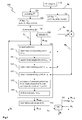
- Fig.1 shows, in an embodiment of the present invention, a flow-chart of a method for performing super-resolution processing of a low resolution input data structure S 0 of digital 1 D, 2D or 3D data.
- the method comprises steps of filtering 170 the input data structure S 0 by a first low-pass filter F l,0 , wherein a low-frequency input data structure L 0 is obtained, calculating in an adder/subtractor 180 a difference between the input data structure S 0 and the low-frequency input data structure L 0 , whereby a high-frequency input data structure H 0 is generated, upscaling 120 the input data structure S 0 , and filtering 130 the upscaled input data structure by a second low-pass filter F l,1 , wherein a low-frequency upscaled data structure L 1 is obtained, determining in the low-frequency upscaled data structure L 1 a first patch P n,L1 at a first position, searching 151,152,154 in the low-frequency
- the upscaled input data structure after filtering 130 by the second low-pass filter F l,1 is downscaled 140 by a downscaling factor d, with n > d .
- a total non-integer upscaling factor nld is obtained for the low-frequency upscaled data structure L 1 .
- the high-frequency upscaled data structure H 1,init (or H 1 respectively) has the same size as the low-frequency upscaled data structure L 1 .
- the size of H 1 may be pre-defined, or derived from L 1 .
- H 1 is initialized in an initialization step 160 to an empty data structure H 1,init of this size.
- Fig.2 shows the principle of the synthesis of the high-frequency band H 1 of a super-resolved (i.e. high resolution) image by extrapolation of the high-frequency information of similar patches at the original resolution scale H 0 .
- the high-frequency high-resolution data structure H 1 is mentioned, actually the unfiltered, non-normalized high-frequency high-resolution data structure H 1,acc is meant.
- the low-frequency band of the high-resolution image L 1 is first divided into small patches P n,L1 ( e.g . 5x5 pixels) with a certain overlap.
- the choice of the amount of overlap trades-off robustness to high-frequency artifacts (in the case of more overlap) and computation speed (in the case of less overlap).
- an overlap of 20-30% in a each direction is selected, i.e. for adjacent patches with e.g. 5 values, 2 values overlap.
- the overlap is higher, e.g. 30-40%, 40-50%, around 50% (e.g. 45-55%) or up to 90%.
- the below-described effect of the invention is usually lower.
- the final high-frequency band H 1 is obtained after normalizing by the number of patches contributing to each pixel, thus resulting in an average value.
- a best match in terms of mean absolute difference (MAD, known from motion estimation) is obtained after an exhaustive search in a local search window (e.g. 11x11 pixels) over the low-frequency band L 0 of the low-resolution image.
- the best match is a block P n,L0 from the low-frequency high-resolution image L 0 that has the same size as the low-frequency high-resolution patch P n,L1 (e.g.5x5 pixels). More details about the search window are described below with respect to Fig.4 .
- the low-resolution low-frequency data structure L 0 has the same dimension as the low-resolution high-frequency data structure H 0
- the high-resolution low-frequency data structure L 1 has the same dimension as the high-resolution high-frequency data structure H 1 . as shown in Fig.2 .
- the position of the matched low-frequency low-resolution patch P n,L0 (within L 0 ) is determined, and the corresponding low-resolution high-frequency patch P n,H0 (within H 0 ) at the position of the matched low-frequency low-resolution patch P n,L0 is extracted.
- the extracted low-resolution high-frequency patch P n,H0 from H 0 is then accumulated on the high-frequency band of the high-resolution image H 1 , at the same position that the current patch P n,L1 in the high-resolution low-frequency data structure L 1 has.
- each value (e.g. pixel) of the extracted low-resolution high-frequency patch P n,H0 from H 0 is accumulated on the corresponding value (e.g. pixel) in the respective patch of the high-frequency band of the high-resolution image H 1 .
- the high-frequency band of the high-resolution image H 1 is synthesized by patch-wise accumulation.
- the process of dividing the low-frequency band of the high-resolution image L 1 in overlapping patches, finding the best low-frequency match and accumulating the corresponding high-frequency contribution is illustrated in Fig. 3 , and is described below.
- each value in the resulting (preliminary) high-frequency band of the high-resolution data structure H 1 is a sum of values from a plurality of contributing patches. Due to the patch overlap in L 1 (and consequently also in H 1 since both have the same dimension), values from at least two patches contribute to many or all values in H 1 . Therefore, the resulting (preliminary) high-frequency band of the high-resolution data structure H 1 is normalized 190. For this purpose, the number of contributing values from H 0 for each value in the high-frequency high resolution data structure H 1 is counted during the synthesis process, and each accumulated value in H 1,acc is eventually divided by the number of contributions.
- Fig.3 shows, exemplarily, usage and positioning of a search window within the low-resolution low-frequency data structure L 0 .
- a first best matching block P 11,L0 is searched in L 0 within a first search window W 11 .
- Both patches have the same size.
- the search window is larger than the patch by at least one value in each direction (except on edges, as for the first patch).
- the first best matching block P 11,L0 is found in L 0 in the upper left corner of the first search window W 11 .
- the further process for this patch and block is as described above. Then, subsequent patches are shifted horizontally and/or vertically, wherein each patch overlaps a previous patch.
- a second patch P 12,L1 is selected at a position that is shifted horizontally by a given patch advance.
- Patch advance is the difference between patch size and overlap.
- Patch advances in different dimensions may differ, which may lead to different effects or qualities in the dimensions of the high-resolution output data structure, but they are usually equal.
- a new search window W 12 is determined according to the new patch position. In principle, the search windows advance in the same direction as the patch, but slower. Thus, a current search window may be at the same position as a previous search window, as is the case here. However, since another patch P 12,L1 is searched in the search window, the position of the best matching patch P 12,L0 will usually be different.
- the best matching patch P 12,L0 is then accumulated to the high-resolution high-frequency data structure H 1 at the position of the low-frequency high-resolution patch P 12,L1 , as described above.
- Subsequent patches P 13,L1 , P 14,L1 are determined and their best matches are searched in the same way.
- the position of the best matching block within the search window is arbitrary and depends on the input data (e.g. the image content).
- vertical patch advance (this may or may not be combined with a horizontal patch advance).
- vertical patch advance includes an overlap, as mentioned above and shown in Fig.3 for P 21,L1 ,..., P 23,L1 .
- the position of the search window is determined according to the position of the current patch. As shown in Fig.3 , the search windows W 11 ,...,W 22 of different patches overlap. Since L 0 is a smaller data structure than L 1 , the search window advance in each dimension is very small. In one embodiment, the search windows are on the edge of L 0 if their corresponding patch is on an edge of L 1 , and it is uniformly and/or proportionally moved in between these edges.
- the center of the search window is set at a position that is substantially proportional to the center of the patch.
- the center of a patch is at 3% of the high-resolution data structure L 1
- the center of the search window is set to be at approximately 3% (rounded) of the low-resolution data structure L 0 .
- the search window size may be reduced, or the search window may be shifted completely into the low-resolution data structure L 0 .
- the larger the search window the more likely it is to find a very similar patch.
- little difference in accuracy is to be expected by largely increasing the search window, since the local patch structure is more likely to be found only in a very local region in general natural images.
- a larger search window requires more processing during the search.
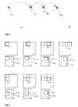
- Fig.4 shows details of the selection of successive patches in an image (i.e. a 2D input data structure), overlap and the principle of determining matching blocks for successive patches.
- patches and blocks have 5x5 pixels and search windows have 12x12 pixels.
- a search window W 1 is determined in L 0 , as described above.
- a block B 1,L0 is determined that has the least mean absolute difference (MAD). This is the best matching block.
- MAD mean absolute difference
- a corresponding patch at the same position in the high-frequency low-resolution image H 0 is determined.
- it is a 5x5 pixel patch with its upper left corner being in the third column and third row.
- This patch is extracted from H 0 and added to H 1 at the position of the current low-frequency high-resolution patch P 1,L1 , i.e. at the upper left corner of H 1 (see Fig.4 a) .
- the second patch P 2,L1 is selected according to the employed patch advance, as shown in Fig.4 b) .
- the patch advance is in this case two pixels in both dimensions, which means that due to the patch size of 5x5 pixels, the overlap is three.
- vertical overlap Vv and horizontal overlap V h are equal.
- the search window W 2 is the same as for the previous patch.
- another best matching block B 2,L0 within the search window is found. In the same manner as described above, its position is determined (e.g.
- the corresponding 5x5 block (with upper left corner in the 7 th column, 2 nd row) is extracted from H 0 , and the extracted block from H 0 is added to the high-frequency high-resolution image H 1 at the position of the second patch P 2,L1 , i.e. with its upper left corner at the first row, third column.
- a particular pixel that belongs to two or more different patches is accumulated from corresponding pixels of to the best matching blocks.
- a particular pixel s in the 4 th column, 5 th row of the high-resolution high-frequency image H 1 has, at the current stage of the process as described, a value that is accumulated from a pixel at the 6 th column, 7 th row (from the best-matching block B 1,L0 of the first patch) and from a pixel at the 8 th column, 6 th row (from the best-matching block B 2,L0 of the second patch).
- the search window advances usually only after a plurality of patches have been processed. As shown exemplarily in Fig.4 c) for the above-described configuration, it takes three patch advances (i.e. the 4 th patch) before the search window W 3 is shifted by one pixel in horizontal direction. Further, it is noted here that the sequential order of various dimensions of the patch advance (and thus search window advance) makes no difference.
- the patch depicted in Fig.4 d) may be processed after previous patches have shifted until the right-hand edge of L 1 , but it may also be processed directly after the first patch as shown in Fig.4 a) .
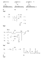
- Fig.5 shows a corresponding example for a 1D data structure.
- a first patch (with values denoted x) at a position #1... #4 of a low-frequency high-resolution data structure L 1 is located within a search window w 1 in the low-frequency low-resolution data structure L 0 , e.g. values at positions #2...#5.
- values of the corresponding H 0 (not shown) at the positions #2...#5 are added to H 1 (not shown) at the positions #1...#4.
- a second patch at a position #3... #6 of L 1 is located within a second search window w 2 in L 0 , e.g. at positions #3...#6 of L 0 (positions #2...#5 of the search window).
- values of the corresponding H 0 (not shown) at the positions #3...#6 are added to H 1 (not shown) at the positions #2...#5, and so on.
- Fig.6 shows the principle of the formation of the up-scaled low-frequency band L 1 of the high-resolution image and two-band analysis (L 0 ,H 0 ) of the low-resolution input image S 0 .
- the goal of this first stage of the method is to obtain the low-frequency band of the high-resolution image L 1 , with an up-scaling factor that in one embodiment is fractional, and a low-resolution image L 0 with the same normalized bandwidth, besides the residual high-frequency component H 0 of the low-resolution image.
- a two-band analysis of the low-resolution input image S 0 into a low-frequency portion L 0 and a high-frequency portion H 0 is performed.
- the cut-off normalized frequency of the low-resolution image is equivalent to that of the high-resolution image.
- separable filters are used in order to avoid large convolutions with square Point Spread Functions (PSFs).
- the design of the two filters shown in Fig.6 is mainly determined by the rational up-scaling factor n/d and an arbitrary choice of the order No of the low-resolution FIR filter F l, 0 .
- the choice of the order is determined by the available computing time for convolution. Generally, values in the order of 8...16 should suffice for providing a steep enough transition band.
- N+1 filter coefficients By choosing even values for the order N, resulting in N+1 filter coefficients, additional phase shifts are avoided and a more accurate high-frequency band is obtained.
- Both low-pass filters F l, 1 and F l, 0 are real and have linear phase, i.e. they are finite impulse response (FIR) filters.
- the normalized gain of every filter at the corresponding cut-off frequency is defined as -6 dB.
- the coefficients are defined as a discrete sinc function with a Hamming window of length N+1.
- the filter magnitude is generally defined as the scaling at the center of the low-pass band after windowing.
- the first filter to design is the high-resolution interpolating filter F l, 1 .
- the desired order N for the low-resolution filter F l. 0 the rational up-scaling factor n/d and the design rules from the previous paragraph, the only missing parameters are the scaling ⁇ 1 (in order to cope with the n zeros that have been inserted between known samples), the order for the high-resolution filter N 1 and its cut-off normalized frequency ⁇ 1 .
- the cut-off frequency obeys to the requirement of eliminating the spectral replicas originated by the insertion of zeros between existing samples.
- the analyzed low-frequency components of the low-resolution input image match, in terms of normalized bandwidth, the low-frequency component of the desired high-resolution image.
- the analyzed high-frequency component of the low-resolution image can be used for estimating the missing high-frequency band of the high-resolution image.
- the purpose of the second stage of the invention is to synthesize the high-frequency band of the high-resolution image by exploiting local self-similarity in the input image. This is done is a per-small patch basis; the method will in general benefit from using smaller magnification factors, due to the availability of a wider frequency bandwidth (increased information) for the analyzed low-frequency component of the low-resolution image, which provides a better selectivity for image patches with similar low-frequency contents. This is schematically illustrated in Fig.7 . Further details of the method are discussed in the following
- Fig.7 shows exemplarily a conceptual block diagram 700 of the process for synthesizing the high-frequency band of the super-resolved image (H 1 , initially set to 0), which is done in principle by extrapolating the high-frequency band of the low-resolution image H 0 .
- the signals W 1 (t) and W 0 (t) are spatial windows with positions varying in time accordingly to the current image patches being processed, and symbolize the patch advance and the search window advance, respectively. That is, e.g. the advance and overlap of the small patches (e.g.
- 5x5 pixels) into which the low-frequency band of the high-resolution image L 1 is divided can be understood as a window W 1 (t) that advances at a first speed within the low-frequency high-resolution data structure L 1 , and at the same within the high-frequency bands of the high-resolution data structure H 1 .
- the advance of the search window over the low-frequency band of the low-resolution image L 0 is modeled by the time-varying window W 0 (t), which is in the same manner applied to the high-frequency band of the low-resolution image H 0 .
- a search unit 710 performs an exhaustive search for a best matching block (i.e. the one having minimum SAD) within the search window.
- the third stage is the formation of the final high-resolution image.
- the goal of this stage is to properly fuse the low-frequency band of the high-resolution image L 1 with the normalized high-frequency band of the high-resolution image H 1 .
- the normalized high-frequency high-resolution band H 1 can be high-pass filtered prior to the addition with the low-frequency high-resolution band L 1 .
- This high-pass filtering is advantageous in order to ensure spectral compatibility, but can be omitted when L 1 and H 1 have substantially no overlapping frequencies (cf.Fig.8 b).
- Fig.8 shows exemplarily the fusion of the low-frequency high-resolution band L 1 and the normalized high-frequency high-resolution band H 1 for generating the super-resolved image S 1 .
- the normalized high-frequency band H 1 is filtered using a high-pass filter 800 in order to ensure the spectral compatibility with the low-frequency band.
- the filter F h,1 is designed in the same fashion as the filters F l,0 ,F l,1 in the first stage.
- the final coefficients of the separable high-pass filter are set to a Kronecker delta aligned with the center of the Hamming window minus the coefficients of the complementary low-pass filter with the same cut-off frequency.
- the high-pass filter is defined as an all pass-filter (set of coefficients equals a Kronecker delta ) minus a low-pass filter with the same cut-off frequency as the desired high-pass filter.
- Fig.8 b This is graphically shown in Fig.8 b), where the left-hand side is the desired frequency response HP of the high-pass filter and the right-hand side is the difference of the responses of an all-pass filter AP and the above described low-pass filter LP.
- the low-frequency band of the high-resolution image L 1 is obtained in principle by interpolation, while the high-frequency band of the high-resolution image H 1 is obtained in principle by extrapolation.
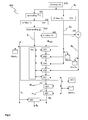
- Fig.9 shows an apparatus for performing super-resolution processing of a low resolution input data structure S 0 of digital data, comprising a first low-pass filter 970 for filtering the input data structure S 0 , wherein a low-frequency input data structure L 0 is obtained, an adder, subtractor or differentiator 980 for calculating a difference between the input data structure S 0 and the low-frequency input data structure L 0 , whereby a high-frequency input data structure H 0 is generated, an upscaler 920 for upscaling the input data structure S 0 , a second low-pass filter 930 for filtering the upscaled input data structure, wherein a low-frequency upscaled data structure L 1 is obtained, a first determining unit 951 for determining in the low-frequency upscaled data structure L 1 a first patch at a first position, a search unit 952 for searching in the low-frequency input data structure L 0 a first block that matches the first patch best, and a second determining 954 unit for
- the method further comprises a step of determining 151,152 a first search window W 1 in the low-frequency input data structure L 0 , wherein the first search window W 1 covers an area around a block at a position that corresponds to said first position in the high-frequency upscaled data structure L 1 , and wherein the searching 152,154 in the low-frequency input data structure L 0 is performed only within the first search window W 1 .
- the step of determining 151,152 a search window W 1 in the low-frequency input data structure L 0 is repeated for each new patch in the low-frequency upscaled data structure L 1 .
- the area that is covered by the search window comprises a plurality of values in each direction of the low-frequency upscaled data structure L 0 around the block at the position corresponding to said first position in the high-frequency upscaled data structure L 1 .
- each new patch P n,L1 in the low-frequency upscaled data structure L 1 overlaps with at least one previously processed patch.
- the low-frequency upscaled data structure L 1 is obtained by upscaling 120 the input data structure S 0 by an upscaling factor n, filtering 130 the upscaled input data structure by said second low-pass filter F l,1 and downscaling 140 the filtered upscaled input data structure in a downscaling unit 940 by a downscaling factor d, with n > d .
- a final non-integer upscaling factor nld is obtained.
- the first low-pass filter F l,0 and the second low-pass filter F l,1 are equivalent filters (i.e., with respect to normalized cut-off frequency).
- the method further comprises a step of filtering the high-frequency upscaled data structure H 1,acc with a high-pass filter F h,1 .
- the method further comprises steps of determining a new patch P n,L1 in the low-frequency upscaled data structure L 1 , searching 152,154 in the low-frequency input data structure L 0 a block B n,L0 that matches the selected patch P n,L1 best, selecting 155 a corresponding block B n,H0 in the high-frequency input data structure H 0 and accumulating 157 pixel data of the selected corresponding block B n,H0 to a patch P n,H1 in the high-frequency upscaled data structure H 1,acc at the position of said new patch P n,L1 are repeated for all patches until the complete low-frequency upscaled data structure L 1 is covered.
- the method further comprises a step of counting the number of contributions per pixel in the high-frequency upscaled data structure H 1,acc , i.e. the number of blocks from the high-frequency input data structure H 0 that contributed to a pixel of the high-frequency upscaled data structure H 1,acc .
- the step of normalizing 190 comprises then dividing the accumulated value per pixel in H 1,acc by the number of contributions.
- the input data structure is a 2D digital image. In another embodiment, the input data structure is a 3D digital image.
- a digital image may generally be part of a digital video sequence.
- the input data structure comprises digital 2D data
- each block and each patch comprise at least 5x5 values
- the search window covers at least 9x9 values and each patch overlaps at least one earlier processed patch by at least 2 values.
- the apparatus further comprises at least one memory MemL 0 , MemL 1 , MemH 0 , MemH 1 for intermediate storage of at least one of the low-frequency input data structure L 0 , the low-frequency upscaled data structure L 1 , the high-frequency input data structure H 0 and the high-frequency upscaled data structure H 1 .
- the apparatus further comprises within the search unit 952 a search window determining unit for determining a search window W 1 in the low-frequency input data structure L 0 , wherein the search window W 1 covers an area around a block at a position that corresponds to said first position in the high-frequency upscaled data structure L 1 , and wherein the search unit 952 searches in the low-frequency input data structure L 0 only within the first search window W 1 .
- the apparatus further comprises a counter 953 for counting the number of contributions per pixel in the high-frequency upscaled data structure H 1,acc .
- the normalizing unit 990 performs an operation of dividing the accumulated value per pixel by the number of contributions.
- Fig.10 shows, in a) and b), an image and its original spectrum.
- Fig. 10 c) shows the spectrum of the image after it was upscaled according to the invention
- Fig.10 d the spectrum of the image after it was conventionally upscaled using the known bi-cubic interpolation.
- the clipped spectrum of the conventionally upscaled image is improved, which is in this example visible in additional values along the diagonals.
- the frequency spectrum shows clearly how the disclosed method is able to plausibly extrapolate the missing high frequencies of the up-scaled image (they can be observed in sharper contours in the up-scaled images, which result in more visually appealing images), whereas bi-cubic interpolation introduces a large amount of aliasing artifacts
- Fig.11 shows the three principle stages comprised in the disclosed method for super-resolving a single image.
- a first stage 1110 an interpolation-based up-scaling of the input image is performed, followed by an equivalent low-pass filtering operation on the low-resolution image.
- the second stage 1120 comprises a search for low-frequency matches between an inspected patch in the high-resolution image and patches in a local neighborhood in the low-resolution low-frequency image, including partly overlapping patches, and accumulating the high-frequency contribution obtained from the low-resolution image.
- the third stage 1130 comprises normalizing and high-pass filtering , and adding the contributions of the low-frequency band of the high-resolution image and the extrapolated, high-pass filtered, normalized high-frequency band.
- the disclosed method works with a single-image, but advantageously without requiring a data-base for retrieving adequate examples containing high-frequency portions (i.e. details).
- the disclosed method is comparatively computationally efficient (it requires only a single-image, and the main processing step is a small-scale local search), flexible in the definition of the up-scaling factor (it enables rational up-scaling factors and straightforward FIR filter design) and can also be generalized for processing signals of different nature (no prior assumptions on the signal model, beyond local self-similarity, are required).
- a further advantage of the invention is that only a single upscaling procedure of the input data structure is employed, and the extrapolation is made from the input data structure at its original resolution.
- the amount of artifacts introduced by upscaling is minimized, which is particularly advantageous for rational upscaling factors, and a broad high-frequency band is available for augmenting the information in the high-frequency high-resolution data structure.
- a further advantage of the invention is that explicit, simple rules for designing the filters are provided, and that the filters need to be designed only once, since they are space-invariant.
- a further advantage of the invention is that, due to the spatial averaging, the high-frequency high-resolution data structure H 1 is more robust to noise and other artifacts than others that are obtained with conventional methods.
- a further advantage of the invention is that the procedure for fusing the interpolated low-frequency high-resolution band L 1 and the extrapolated high-frequency high-resolution band H 1 takes the spectral coherence between them into consideration. This is achieved by appropriate design of the high-pass filter for the high-frequency high-resolution data structure.
Landscapes
- Physics & Mathematics (AREA)
- General Physics & Mathematics (AREA)
- Engineering & Computer Science (AREA)
- Theoretical Computer Science (AREA)
- Image Processing (AREA)
- Editing Of Facsimile Originals (AREA)
Priority Applications (10)
| Application Number | Priority Date | Filing Date | Title |
|---|---|---|---|
| EP12305046.0A EP2615579A1 (en) | 2012-01-12 | 2012-01-12 | Method and device for generating a super-resolution version of a low resolution input data structure |
| CN201380010408.0A CN104137143A (zh) | 2012-01-12 | 2013-01-11 | 生成低分辨率输入数据结构的超分辨率版本的方法和设备 |
| EP13700174.9A EP2803036B1 (en) | 2012-01-12 | 2013-01-11 | Method and device for generating a super-resolution version of a low resolution input data structure |
| KR1020147019119A KR20140116406A (ko) | 2012-01-12 | 2013-01-11 | 저해상도 입력 데이터 구조의 초고해상도 버전을 생성하기 위한 방법 및 장치 |
| AU2013208922A AU2013208922A1 (en) | 2012-01-12 | 2013-01-11 | Method and device for generating a super-resolution version of a low resolution input data structure |
| BR112014016768A BR112014016768A8 (pt) | 2012-01-12 | 2013-01-11 | método e dispositivo para a geração de uma versão de super resolução de uma estrutura de dados de entrada de baixa resolução |
| PCT/EP2013/050466 WO2013104747A1 (en) | 2012-01-12 | 2013-01-11 | Method and device for generating a super-resolution version of a low resolution input data structure |
| US14/371,178 US9245326B2 (en) | 2012-01-12 | 2013-01-11 | Method and device for generating a super-resolution version of a low resolution input data structure |
| JP2014551624A JP2015507273A (ja) | 2012-01-12 | 2013-01-11 | 低解像入力データ構造の超解像バージョンを生成する方法及び装置 |
| HK15104583.8A HK1204126A1 (zh) | 2012-01-12 | 2015-05-14 | 生成低分辨率輸入數據結構的超分辨率版本的方法和設備 |
Applications Claiming Priority (1)
| Application Number | Priority Date | Filing Date | Title |
|---|---|---|---|
| EP12305046.0A EP2615579A1 (en) | 2012-01-12 | 2012-01-12 | Method and device for generating a super-resolution version of a low resolution input data structure |
Publications (1)
| Publication Number | Publication Date |
|---|---|
| EP2615579A1 true EP2615579A1 (en) | 2013-07-17 |
Family
ID=47553088
Family Applications (2)
| Application Number | Title | Priority Date | Filing Date |
|---|---|---|---|
| EP12305046.0A Withdrawn EP2615579A1 (en) | 2012-01-12 | 2012-01-12 | Method and device for generating a super-resolution version of a low resolution input data structure |
| EP13700174.9A Active EP2803036B1 (en) | 2012-01-12 | 2013-01-11 | Method and device for generating a super-resolution version of a low resolution input data structure |
Family Applications After (1)
| Application Number | Title | Priority Date | Filing Date |
|---|---|---|---|
| EP13700174.9A Active EP2803036B1 (en) | 2012-01-12 | 2013-01-11 | Method and device for generating a super-resolution version of a low resolution input data structure |
Country Status (9)
| Country | Link |
|---|---|
| US (1) | US9245326B2 (ja) |
| EP (2) | EP2615579A1 (ja) |
| JP (1) | JP2015507273A (ja) |
| KR (1) | KR20140116406A (ja) |
| CN (1) | CN104137143A (ja) |
| AU (1) | AU2013208922A1 (ja) |
| BR (1) | BR112014016768A8 (ja) |
| HK (1) | HK1204126A1 (ja) |
| WO (1) | WO2013104747A1 (ja) |
Cited By (4)
| Publication number | Priority date | Publication date | Assignee | Title |
|---|---|---|---|---|
| CN105072373A (zh) * | 2015-08-28 | 2015-11-18 | 中国科学院自动化研究所 | 基于双向循环卷积网络的视频超分辨率方法和系统 |
| US9258518B2 (en) | 2012-03-05 | 2016-02-09 | Thomson Licensing | Method and apparatus for performing super-resolution |
| EP3166070A1 (en) * | 2015-11-09 | 2017-05-10 | Thomson Licensing | Method for upscaling noisy images, and apparatus for upscaling noisy images |
| CN107680043A (zh) * | 2017-09-29 | 2018-02-09 | 杭州电子科技大学 | 基于图模型的单幅图像超分辨率输出方法 |
Families Citing this family (32)
| Publication number | Priority date | Publication date | Assignee | Title |
|---|---|---|---|---|
| CN104619237B (zh) | 2012-07-26 | 2018-03-30 | 德普伊辛迪斯制品公司 | 光不足环境中的ycbcr脉冲调制的照明方案 |
| JP6526560B2 (ja) | 2012-07-26 | 2019-06-05 | デピュー シンセス プロダクツ, インコーポレーテッドDePuy Synthes Products, Inc. | 光が不十分な環境での連続的なビデオ |
| KR20140086632A (ko) * | 2012-12-28 | 2014-07-08 | 삼성디스플레이 주식회사 | 영상 처리 장치 및 그것을 포함하는 표시 장치 |
| EP2967294B1 (en) * | 2013-03-15 | 2020-07-29 | DePuy Synthes Products, Inc. | Super resolution and color motion artifact correction in a pulsed color imaging system |
| US9777913B2 (en) | 2013-03-15 | 2017-10-03 | DePuy Synthes Products, Inc. | Controlling the integral light energy of a laser pulse |
| JP6422937B2 (ja) | 2013-03-15 | 2018-11-14 | デピュイ・シンセス・プロダクツ・インコーポレイテッド | 光制御された環境において感知する内視鏡 |
| WO2015115168A1 (ja) * | 2014-01-28 | 2015-08-06 | シャープ株式会社 | 画像処理装置 |
| US9734558B2 (en) * | 2014-03-20 | 2017-08-15 | Mitsubishi Electric Research Laboratories, Inc. | Method for generating high-resolution images using regression patterns |
| EP3119265B1 (en) | 2014-03-21 | 2019-09-11 | DePuy Synthes Products, Inc. | Card edge connector for an imaging sensor |
| KR101651741B1 (ko) * | 2014-09-30 | 2016-08-26 | 한국전자통신연구원 | 영상의 영역 별로 선명화하는 고해상도 영상 생성 장치 및 방법 |
| CN104580931A (zh) * | 2015-01-22 | 2015-04-29 | 成都索贝数码科技股份有限公司 | 一种图像、视频超分辨率放大的系统与方法 |
| KR102272108B1 (ko) * | 2015-02-27 | 2021-07-05 | 삼성전자주식회사 | 영상 처리 장치 및 방법 |
| CN105405106A (zh) * | 2015-10-22 | 2016-03-16 | 华南农业大学 | 一种单图像超分辨率重建的方法 |
| US10282831B2 (en) * | 2015-12-28 | 2019-05-07 | Novatek Microelectronics Corp. | Method and apparatus for motion compensated noise reduction |
| WO2017124036A1 (en) * | 2016-01-16 | 2017-07-20 | Flir Systems, Inc. | Systems and methods for image super-resolution using iterative collaborative filtering |
| EP3452983A4 (en) * | 2016-05-04 | 2019-04-10 | Tel HaShomer Medical Research Infrastructure and Services Ltd. | METHOD AND SYSTEM FOR PROVIDING A LOCALLY CONSISTENT IMPROVEMENT OF A MINIMUM IMAGE |
| TW201742001A (zh) * | 2016-05-30 | 2017-12-01 | 聯詠科技股份有限公司 | 影像雜訊估測方法及裝置與影像擷取裝置 |
| KR101795271B1 (ko) | 2016-06-10 | 2017-11-07 | 현대자동차주식회사 | 영상의 선명화를 위한 전처리를 수행하는 영상 처리 장치 및 방법 |
| KR102580519B1 (ko) * | 2016-09-07 | 2023-09-21 | 삼성전자주식회사 | 영상처리장치 및 기록매체 |
| US10621446B2 (en) * | 2016-12-22 | 2020-04-14 | Texas Instruments Incorporated | Handling perspective magnification in optical flow processing |
| US10204428B2 (en) | 2017-02-02 | 2019-02-12 | Muhannad Salem S. ALMUTIRY | Systems and method for reconstructing 3D radio frequency tomographic images |
| KR20180097342A (ko) * | 2017-02-23 | 2018-08-31 | 한국전자통신연구원 | 영상 아티팩트를 최소화하는 초해상도 영상 선명화 방법 및 장치 |
| KR102351083B1 (ko) * | 2017-08-30 | 2022-01-13 | 삼성전자주식회사 | 디스플레이 장치 및 그 영상 처리 방법 |
| US11004178B2 (en) | 2018-03-01 | 2021-05-11 | Nvidia Corporation | Enhancing high-resolution images with data from low-resolution images |
| CN109949221B (zh) * | 2019-01-30 | 2022-05-17 | 深圳大学 | 一种图像处理方法及电子设备 |
| KR20210017185A (ko) * | 2019-08-07 | 2021-02-17 | 한국전자통신연구원 | 심층 신경망을 기반으로 영상의 압축 포아송 잡음을 제거하는 방법 및 장치 |
| CN111666896A (zh) * | 2020-06-09 | 2020-09-15 | 中国科学院地理科学与资源研究所 | 一种基于线性融合模型的遥感影像时空融合方法 |
| CN111667410B (zh) * | 2020-06-10 | 2021-09-14 | 腾讯科技(深圳)有限公司 | 图像分辨率提升方法、装置及电子设备 |
| CN113449784B (zh) * | 2021-06-18 | 2024-04-05 | 宜通世纪科技股份有限公司 | 基于先验属性图谱的图像多分类方法、装置、设备及介质 |
| CN113592713A (zh) * | 2021-08-02 | 2021-11-02 | 哈尔滨理工大学 | 一种基于生成对抗网络的文物图像超分辨率方法 |
| US20230262259A1 (en) * | 2022-02-14 | 2023-08-17 | Microsoft Technology Licensing, Llc | Unified Space-Time Interpolation of Video Information |
| US20230298212A1 (en) * | 2022-03-17 | 2023-09-21 | Advanced Micro Devices, Inc. | Locking mechanism for image classification |
Citations (1)
| Publication number | Priority date | Publication date | Assignee | Title |
|---|---|---|---|---|
| WO2010122502A1 (en) * | 2009-04-20 | 2010-10-28 | Yeda Research And Development Co. Ltd. | Super-resolution from a single signal |
Family Cites Families (13)
| Publication number | Priority date | Publication date | Assignee | Title |
|---|---|---|---|---|
| US6307569B1 (en) | 1999-03-18 | 2001-10-23 | Sharp Laboratories Of America, Inc. | POCS-based method for digital image interpolation |
| EP1661086A1 (en) | 2003-08-28 | 2006-05-31 | Koninklijke Philips Electronics N.V. | Method for spatial up-scaling of video frames |
| CN1655620B (zh) | 2004-02-09 | 2010-09-22 | 三洋电机株式会社 | 图像显示装置 |
| US8467459B2 (en) * | 2004-10-13 | 2013-06-18 | Thomson Licensing | Method and apparatus for complexity scalable video encoding and decoding |
| US7327904B2 (en) * | 2004-12-15 | 2008-02-05 | Arcsoft, Inc. | Pattern classification and filter design for increasing image resolution |
| KR100655040B1 (ko) | 2005-11-24 | 2006-12-06 | 주식회사 휴맥스 | 디지털 영상신호 스케일링 방법 |
| JP5232796B2 (ja) * | 2006-12-14 | 2013-07-10 | トムソン ライセンシング | 適応エンハンスメントレイヤ予測を使用したビット深度スケーラブルなビデオデータを符号化及び/又は復号化する方法及び装置 |
| JP5012333B2 (ja) * | 2007-08-30 | 2012-08-29 | コニカミノルタアドバンストレイヤー株式会社 | 画像処理装置および画像処理方法ならびに撮像装置 |
| JP5076755B2 (ja) * | 2007-09-07 | 2012-11-21 | ソニー株式会社 | 画像処理装置、および画像処理方法、並びにコンピュータ・プログラム |
| KR101590765B1 (ko) * | 2009-07-21 | 2016-02-19 | 삼성전자주식회사 | 다중 대역 합성 필터를 이용한 고해상도 영상 획득 장치 및 방법 |
| KR20110065089A (ko) | 2009-12-09 | 2011-06-15 | 삼성전자주식회사 | 영상의 부호화 방법 및 장치, 그 복호화 방법 및 장치 |
| EP2529353A1 (en) | 2010-01-28 | 2012-12-05 | Yissum Research Development Company of the Hebrew University of Jerusalem, Ltd. | Method and system for generating an output image of increased pixel resolution from an input image |
| JP5706177B2 (ja) | 2010-02-09 | 2015-04-22 | パナソニック インテレクチュアル プロパティ コーポレーション オブアメリカPanasonic Intellectual Property Corporation of America | 超解像処理装置及び超解像処理方法 |
-
2012
- 2012-01-12 EP EP12305046.0A patent/EP2615579A1/en not_active Withdrawn
-
2013
- 2013-01-11 EP EP13700174.9A patent/EP2803036B1/en active Active
- 2013-01-11 KR KR1020147019119A patent/KR20140116406A/ko not_active Application Discontinuation
- 2013-01-11 WO PCT/EP2013/050466 patent/WO2013104747A1/en active Application Filing
- 2013-01-11 US US14/371,178 patent/US9245326B2/en active Active
- 2013-01-11 JP JP2014551624A patent/JP2015507273A/ja active Pending
- 2013-01-11 CN CN201380010408.0A patent/CN104137143A/zh active Pending
- 2013-01-11 AU AU2013208922A patent/AU2013208922A1/en not_active Abandoned
- 2013-01-11 BR BR112014016768A patent/BR112014016768A8/pt active Search and Examination
-
2015
- 2015-05-14 HK HK15104583.8A patent/HK1204126A1/zh not_active IP Right Cessation
Patent Citations (1)
| Publication number | Priority date | Publication date | Assignee | Title |
|---|---|---|---|---|
| WO2010122502A1 (en) * | 2009-04-20 | 2010-10-28 | Yeda Research And Development Co. Ltd. | Super-resolution from a single signal |
Non-Patent Citations (11)
| Title |
|---|
| D. GLASNER; S. BAGON; M. IRANI: "Super-Resolution from a Single Image", IEEE INT. CONF. ON COMPUTER VISION, 2009 |
| G. FREEDMAN; R. FATTAL: "Image and Video Upscaling from Local Self-Examples", ACM TRANS. ON GRAPHICS, 2010 |
| HAICHAO ZHANG ET AL: "Multi-scale Non-Local Kernel Regression for super resolution", IMAGE PROCESSING (ICIP), 2011 18TH IEEE INTERNATIONAL CONFERENCE ON, IEEE, 11 September 2011 (2011-09-11), pages 1353 - 1356, XP032079840, ISBN: 978-1-4577-1304-0, DOI: 10.1109/ICIP.2011.6115688 * |
| JUEPING BIAN ET AL: "Improved SAI method using non-local spatial constraint for image interpolation", WIRELESS COMMUNICATIONS AND SIGNAL PROCESSING (WCSP), 2011 INTERNATIONAL CONFERENCE ON, IEEE, 9 November 2011 (2011-11-09), pages 1 - 4, XP032100974, ISBN: 978-1-4577-1009-4, DOI: 10.1109/WCSP.2011.6096772 * |
| M. IRANI; S. PELEG: "Super Resolution from Image Sequences", INT. CONF. ON PATTERN RECOGNITION, 1990 |
| O. SHAHAR; A. FAKTOR; M. IRANI: "Space-Time Super-Resolution from a Single Video", IEEE CONF. ON COMPUTER VISION AND PATTERN RECOGNITION, 2011 |
| SHAHRYAR SHAFIQUE QURESHI ET AL: "Investigating image super resolution techniques: What to choose?", ADVANCED COMMUNICATION TECHNOLOGY (ICACT), 2012 14TH INTERNATIONAL CONFERENCE ON, IEEE, 19 February 2012 (2012-02-19), pages 642 - 647, XP032153188, ISBN: 978-1-4673-0150-3 * |
| W.T. FREEMAN; T.R. JONES; E.C. PASZTOR, EXAMPLE-BASED SUPER-RESOLUTION |
| W.T. FREEMAN; T.R. JONES; E.C. PASZTOR: "Example-based super-resolution", IEEE COMPUTER GRAPHICS AND APPLICATIONS, 2002 |
| Z. LIN; H.-Y. SHUM, FUNDAMENTAL LIMITS OF RECONSTRUCTION-BASED SUPERRESOLUTION ALGORITHMS UNDER LOCAL TRANSLATION |
| Z. LIN; H.-Y. SHUM, IEEE TRANS. ON PATTERN ANALYSIS AND MACHINE INTELLIGENCE, 2004 |
Cited By (7)
| Publication number | Priority date | Publication date | Assignee | Title |
|---|---|---|---|---|
| US9258518B2 (en) | 2012-03-05 | 2016-02-09 | Thomson Licensing | Method and apparatus for performing super-resolution |
| CN105072373A (zh) * | 2015-08-28 | 2015-11-18 | 中国科学院自动化研究所 | 基于双向循环卷积网络的视频超分辨率方法和系统 |
| CN105072373B (zh) * | 2015-08-28 | 2018-03-27 | 中国科学院自动化研究所 | 基于双向循环卷积网络的视频超分辨率方法和系统 |
| EP3166070A1 (en) * | 2015-11-09 | 2017-05-10 | Thomson Licensing | Method for upscaling noisy images, and apparatus for upscaling noisy images |
| US10319075B2 (en) | 2015-11-09 | 2019-06-11 | Interdigital Ce Patent Holdings | Method for upscaling noisy images, and apparatus for upscaling noisy images |
| CN107680043A (zh) * | 2017-09-29 | 2018-02-09 | 杭州电子科技大学 | 基于图模型的单幅图像超分辨率输出方法 |
| CN107680043B (zh) * | 2017-09-29 | 2020-09-22 | 杭州电子科技大学 | 基于图模型的单幅图像超分辨率输出方法 |
Also Published As
| Publication number | Publication date |
|---|---|
| CN104137143A (zh) | 2014-11-05 |
| EP2803036A1 (en) | 2014-11-19 |
| US9245326B2 (en) | 2016-01-26 |
| BR112014016768A8 (pt) | 2017-07-04 |
| HK1204126A1 (zh) | 2015-11-06 |
| KR20140116406A (ko) | 2014-10-02 |
| WO2013104747A1 (en) | 2013-07-18 |
| US20150023611A1 (en) | 2015-01-22 |
| AU2013208922A1 (en) | 2014-07-24 |
| BR112014016768A2 (pt) | 2017-06-13 |
| EP2803036B1 (en) | 2015-11-04 |
| JP2015507273A (ja) | 2015-03-05 |
Similar Documents
| Publication | Publication Date | Title |
|---|---|---|
| EP2803036B1 (en) | Method and device for generating a super-resolution version of a low resolution input data structure | |
| EP2662825B1 (en) | Method and device for generating a super-resolution version of a low resolution input data structure | |
| US9258518B2 (en) | Method and apparatus for performing super-resolution | |
| Farsiu et al. | Video-to-video dynamic super-resolution for grayscale and color sequences | |
| Siu et al. | Review of image interpolation and super-resolution | |
| CN111275626B (zh) | 一种基于模糊度的视频去模糊方法、装置及设备 | |
| KR101795271B1 (ko) | 영상의 선명화를 위한 전처리를 수행하는 영상 처리 장치 및 방법 | |
| Takeda et al. | Removing motion blur with space–time processing | |
| Jeong et al. | Multi-frame example-based super-resolution using locally directional self-similarity | |
| EP2948920A1 (en) | Method and apparatus for performing single-image super-resolution | |
| Zhao et al. | Single depth image super-resolution with multiple residual dictionary learning and refinement | |
| US20040086201A1 (en) | Fast edge directed polynomial interpolation | |
| Tom et al. | Reconstruction of a high resolution image from multiple low resolution images | |
| Panda et al. | An Improved DCT interpolation using Bilateral filter | |
| KR20070119482A (ko) | 이미지 리샘플링 방법 | |
| Georgis et al. | Single-image super-resolution using low complexity adaptive iterative back-projection | |
| Saito et al. | Demosaicing method using the extended color total-variation regularization | |
| KR101434530B1 (ko) | 적응적 가중치 보간 및 이산 웨이블릿 변환 기반 초해상도 영상 생성 방법 | |
| Vanam et al. | Adaptive bilateral filter for video and image upsampling | |
| Shen et al. | GPU-aided real-time image/video super resolution based on error feedback | |
| Protter et al. | Super-resolution with probabilistic motion estimation | |
| Pan | Improving a single down-sampled image using probability-filtering-based interpolation and improved Poisson maximum a posteriori super-resolution | |
| Bhosale et al. | Image Super Resolution with Direct Mapping and De-Noising | |
| Salvador et al. | Robust super-resolution for interactive video navigation | |
| Lee et al. | Self-synthesis based super-resolution for a natural image |
Legal Events
| Date | Code | Title | Description |
|---|---|---|---|
| PUAI | Public reference made under article 153(3) epc to a published international application that has entered the european phase |
Free format text: ORIGINAL CODE: 0009012 |
|
| AK | Designated contracting states |
Kind code of ref document: A1 Designated state(s): AL AT BE BG CH CY CZ DE DK EE ES FI FR GB GR HR HU IE IS IT LI LT LU LV MC MK MT NL NO PL PT RO RS SE SI SK SM TR |
|
| AX | Request for extension of the european patent |
Extension state: BA ME |
|
| STAA | Information on the status of an ep patent application or granted ep patent |
Free format text: STATUS: THE APPLICATION IS DEEMED TO BE WITHDRAWN |
|
| 18D | Application deemed to be withdrawn |
Effective date: 20140118 |