EP2615477A2 - Neutronenerfassungswerkzeug mit mehreren Detektoren - Google Patents
Neutronenerfassungswerkzeug mit mehreren Detektoren Download PDFInfo
- Publication number
- EP2615477A2 EP2615477A2 EP12190458.5A EP12190458A EP2615477A2 EP 2615477 A2 EP2615477 A2 EP 2615477A2 EP 12190458 A EP12190458 A EP 12190458A EP 2615477 A2 EP2615477 A2 EP 2615477A2
- Authority
- EP
- European Patent Office
- Prior art keywords
- gamma ray
- borehole
- logging tool
- neutron
- neutron logging
- Prior art date
- Legal status (The legal status is an assumption and is not a legal conclusion. Google has not performed a legal analysis and makes no representation as to the accuracy of the status listed.)
- Withdrawn
Links
- 230000015572 biosynthetic process Effects 0.000 claims abstract description 68
- 230000005251 gamma ray Effects 0.000 claims description 124
- 238000000034 method Methods 0.000 claims description 25
- 238000005553 drilling Methods 0.000 claims description 4
- 238000005755 formation reaction Methods 0.000 abstract description 61
- 229910052688 Gadolinium Inorganic materials 0.000 description 9
- UIWYJDYFSGRHKR-UHFFFAOYSA-N gadolinium atom Chemical compound [Gd] UIWYJDYFSGRHKR-UHFFFAOYSA-N 0.000 description 9
- 239000000463 material Substances 0.000 description 8
- 230000000712 assembly Effects 0.000 description 6
- 238000000429 assembly Methods 0.000 description 6
- 238000009826 distribution Methods 0.000 description 6
- 230000004044 response Effects 0.000 description 6
- 230000008901 benefit Effects 0.000 description 5
- 238000012937 correction Methods 0.000 description 5
- 230000002596 correlated effect Effects 0.000 description 5
- 239000012530 fluid Substances 0.000 description 5
- 238000004519 manufacturing process Methods 0.000 description 5
- 239000004215 Carbon black (E152) Substances 0.000 description 4
- 230000000694 effects Effects 0.000 description 4
- 238000011156 evaluation Methods 0.000 description 4
- 229930195733 hydrocarbon Natural products 0.000 description 4
- 150000002430 hydrocarbons Chemical class 0.000 description 4
- 238000001228 spectrum Methods 0.000 description 4
- 230000035945 sensitivity Effects 0.000 description 3
- 239000011358 absorbing material Substances 0.000 description 2
- 239000004568 cement Substances 0.000 description 2
- 238000001514 detection method Methods 0.000 description 2
- 230000007613 environmental effect Effects 0.000 description 2
- 238000002955 isolation Methods 0.000 description 2
- 239000002245 particle Substances 0.000 description 2
- 230000000149 penetrating effect Effects 0.000 description 2
- 230000008569 process Effects 0.000 description 2
- 239000004576 sand Substances 0.000 description 2
- ZOXJGFHDIHLPTG-UHFFFAOYSA-N Boron Chemical compound [B] ZOXJGFHDIHLPTG-UHFFFAOYSA-N 0.000 description 1
- GYHNNYVSQQEPJS-UHFFFAOYSA-N Gallium Chemical compound [Ga] GYHNNYVSQQEPJS-UHFFFAOYSA-N 0.000 description 1
- 229910014323 Lanthanum(III) bromide Inorganic materials 0.000 description 1
- 230000004075 alteration Effects 0.000 description 1
- 229910052788 barium Inorganic materials 0.000 description 1
- DSAJWYNOEDNPEQ-UHFFFAOYSA-N barium atom Chemical compound [Ba] DSAJWYNOEDNPEQ-UHFFFAOYSA-N 0.000 description 1
- 229910052790 beryllium Inorganic materials 0.000 description 1
- 229910052796 boron Inorganic materials 0.000 description 1
- 229910052793 cadmium Inorganic materials 0.000 description 1
- BDOSMKKIYDKNTQ-UHFFFAOYSA-N cadmium atom Chemical compound [Cd] BDOSMKKIYDKNTQ-UHFFFAOYSA-N 0.000 description 1
- 239000013078 crystal Substances 0.000 description 1
- 230000009977 dual effect Effects 0.000 description 1
- 238000001914 filtration Methods 0.000 description 1
- 230000004907 flux Effects 0.000 description 1
- 229910052733 gallium Inorganic materials 0.000 description 1
- 229910052732 germanium Inorganic materials 0.000 description 1
- GNPVGFCGXDBREM-UHFFFAOYSA-N germanium atom Chemical compound [Ge] GNPVGFCGXDBREM-UHFFFAOYSA-N 0.000 description 1
- 230000001939 inductive effect Effects 0.000 description 1
- 238000007689 inspection Methods 0.000 description 1
- 229910052741 iridium Inorganic materials 0.000 description 1
- GKOZUEZYRPOHIO-UHFFFAOYSA-N iridium atom Chemical compound [Ir] GKOZUEZYRPOHIO-UHFFFAOYSA-N 0.000 description 1
- XKUYOJZZLGFZTC-UHFFFAOYSA-K lanthanum(iii) bromide Chemical compound Br[La](Br)Br XKUYOJZZLGFZTC-UHFFFAOYSA-K 0.000 description 1
- WPBNNNQJVZRUHP-UHFFFAOYSA-L manganese(2+);methyl n-[[2-(methoxycarbonylcarbamothioylamino)phenyl]carbamothioyl]carbamate;n-[2-(sulfidocarbothioylamino)ethyl]carbamodithioate Chemical compound [Mn+2].[S-]C(=S)NCCNC([S-])=S.COC(=O)NC(=S)NC1=CC=CC=C1NC(=S)NC(=O)OC WPBNNNQJVZRUHP-UHFFFAOYSA-L 0.000 description 1
- 238000005259 measurement Methods 0.000 description 1
- 238000012986 modification Methods 0.000 description 1
- 230000004048 modification Effects 0.000 description 1
- 238000009828 non-uniform distribution Methods 0.000 description 1
- 238000010606 normalization Methods 0.000 description 1
- 230000035699 permeability Effects 0.000 description 1
- 239000000700 radioactive tracer Substances 0.000 description 1
- 230000000717 retained effect Effects 0.000 description 1
- 229910052712 strontium Inorganic materials 0.000 description 1
- CIOAGBVUUVVLOB-UHFFFAOYSA-N strontium atom Chemical compound [Sr] CIOAGBVUUVVLOB-UHFFFAOYSA-N 0.000 description 1
- 239000000126 substance Substances 0.000 description 1
- 229910052715 tantalum Inorganic materials 0.000 description 1
- GUVRBAGPIYLISA-UHFFFAOYSA-N tantalum atom Chemical compound [Ta] GUVRBAGPIYLISA-UHFFFAOYSA-N 0.000 description 1
- WFKWXMTUELFFGS-UHFFFAOYSA-N tungsten Chemical compound [W] WFKWXMTUELFFGS-UHFFFAOYSA-N 0.000 description 1
- 229910052721 tungsten Inorganic materials 0.000 description 1
- 239000010937 tungsten Substances 0.000 description 1
Images


Classifications
-
- G—PHYSICS
- G01—MEASURING; TESTING
- G01V—GEOPHYSICS; GRAVITATIONAL MEASUREMENTS; DETECTING MASSES OR OBJECTS; TAGS
- G01V5/00—Prospecting or detecting by the use of ionising radiation, e.g. of natural or induced radioactivity
- G01V5/04—Prospecting or detecting by the use of ionising radiation, e.g. of natural or induced radioactivity specially adapted for well-logging
- G01V5/08—Prospecting or detecting by the use of ionising radiation, e.g. of natural or induced radioactivity specially adapted for well-logging using primary nuclear radiation sources or X-rays
- G01V5/10—Prospecting or detecting by the use of ionising radiation, e.g. of natural or induced radioactivity specially adapted for well-logging using primary nuclear radiation sources or X-rays using neutron sources
- G01V5/101—Prospecting or detecting by the use of ionising radiation, e.g. of natural or induced radioactivity specially adapted for well-logging using primary nuclear radiation sources or X-rays using neutron sources and detecting the secondary Y-rays produced in the surrounding layers of the bore hole
Definitions
- fracturing fluid is pumped down a wellbore with high pressure, causing a formation to fracture around a borehole.
- the fracturing fluid contains proppant (e.g. sand and/or other particles), which remains in the formation fractures and acts to "prop" open the fractures in the formation to increase hydrocarbon flow into the wellbore. Without proppant, the formation fractures may close, reducing the effectiveness of the fracturing procedure. Sometimes, other unwanted effects may occur. This may include proppant flowing back up the wellbore or an uneven distribution of proppant within the fractures in the formation.
- the resulting hydrocarbon production from the fractured formation may be less than optimal because of these unwanted effects.
- An example of a reference for hydraulic fracturing and its evaluation is described in the article " Hydraulic fracture evaluation with multiple radioactive tracers," by Pemper et al., Geophysics, Vol. 53, No. 10 (October 1998), at 1323-1333 , which is incorporated herein by reference.
- Logging tools for measuring formation properties before fracturing are known. These tools have been used in the past to log a formation to detect oil and gas formations adjacent to a wellbore. However, there has not been an ability to measure the azimuthal distribution of proppant in formation fractures.
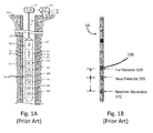
- Fig.1A shows a deployed exemplary neutron logging system as known in the prior art as a cased hole reservoir evaluation tool. This system is similar to the system disclosed in U.S. Pat. No. 7,999,220 , which is incorporated herein by reference in its entirety. Other systems are disclosed in U.S. Pat. Nos. 5,374,823 and 6,376,838 , which are also incorporated herein by reference.
- neutron logging tool 10 is disposed within a borehole 33 penetrating earth formation 40.
- the borehole 33 may be cased with casing 35, and the casing-borehole annulus may be filled with a grouting material such as cement.
- the borehole 33 may be an uncased open hole.
- Subsection 11 houses an array of detector assemblies 100 as well as a neutron generator 102. More specifically, there are four detector assemblies 100,each comprising a LaBr3 detector crystal and digital spectrometer for filtering and pulse inspection. These detectors are referred to as the proximal detector 104, the near detector 106, the far detector 110, and the long detector 112. The detectors are disposed at increasing longitudinal (or axial or vertical) distances from the neutron generator 102. Between the near detector 106 and far detector 110 is a fast neutron detector 108 that measures the fast neutron output flux and pulse shape of the neutron generator 102.
- Subsection 11 is connected to instrument subsection 24.
- Instrument subsection 24 houses control circuits and power circuits to operate and control the elements of subsection 11.
- Additional elements of neutron logging tool 10 include telemetry subsection 26 and connector 28.
- Neutron logging tool 10 is connected by wireline logging cable 30 to above-surface elements such as draw works 34 and surface equipment 36.
- FIG. 1B Another multi-detector neutron logging tool 10, known in the prior art as a pulsed neutron decay tool, is shown in Fig. 1B .
- CRE cased reservoir evaluation tool
- PND pulsed neutron decay tool
- MDN dual neutron tool
- CNT-S and CNT-V compensated neutron tools
- the prior art neutron logging tools such as tool10 in Figs. 1A-1B , are not able to give azimuthal logging information. Rather, the two or more detector assemblies 100 are spaced apart longitudinally along the body of the neutron logging tool 10a short distance from the neutron source102, and the detector assemblies 100 are vertically in line with each other along a central axis of the tool. Yet, the detector assemblies 100 make their detections of the adjacent wall of the borehole without particular regard to direction or orientation. Instead, the intention of the multiple detector assemblies 100 is to provide different formation and statistical sensitivities during logging operations.
- the effect is that the detector assemblies100 closest to the neutron generator 102 typically are more sensitive to the borehole 33, and the detector assemblies100 further from the neutron generator 102 typically are more sensitive to the overall formation 40.
- the sigma ( ⁇ ) capture cross-section of the borehole 33 and formation 40 of the readings may be computed by giving different weights to the near detectors' readings as compared to the far detectors' readings. For example, in a tool with two detectors, 70% weight may be given for the near detector reading and 30% weight for the far detector reading.
- the neutron logging tool 10 is usually run decentralized to the wellbore with an offset spring, or decentralizer,(not shown) such that the neutron logging tool 10 effectively runs along one wall of the wellbore.
- the subject matter of the present disclosure is directed to overcoming, or at least reducing the effects of, one or more of the problems set forth above.
- the subject matter of the present disclosure is directed to developing anazimuthal log that may be used before and/or after fracturing a formation.
- the azimuthal log can characterize the proppant distribution and can be compared to the pre-fracturing formation distribution. This would help an operator make decisions to optimize formation production.
- a neutron logging tool has multiple detectors spaced about the circumference of the tool.
- the detectors are shielded from each other such that each detector detects gamma rays from the area of the borehole and formation to which it is closest.
- the log readings from each detector can be associated with the orientation of that detector.
- the orientation-specific log readings can then be aggregated to form an azimuthal log which can be used to analyze pre-fractured and/or post-fractured formations.
- An aspect of the invention relates to a neutron logging tool for obtaining an azimuthal log of a borehole, the tool comprising:
- Each of the gamma ray detectors may be radially equidistantly displaced from a central axis of the neutron logging tool.
- Each of the gamma ray detectors may not be radially equidistantly displaced from a central axis of the neutron logging tool.
- Each of the gamma ray detectors may not intersect the central axis of the neutron logging tool.
- One or more of the gamma ray detectors may intersect the central axis of the neutron logging tool.
- Each of the gamma ray detectors may be longitudinally equidistant from the neutron source.
- Each of the gamma ray detectors may be displaced at longitudinally different distances from the neutron source.
- the shielding may substantially surround the plurality of gamma ray detectors.
- the shielding may be localized around each of the gamma ray detectors.
- the orientation instrument may be a mechanical device.
- the orientation instrument may be a weighting device.
- Another aspect of the invention relates to a neutron logging tool for obtaining an azimuthal log of a borehole, the tool comprising:
- the rotating member may further comprise a rotation orientation instrument determining second orientation data of the rotating member in the borehole.
- the shielding may substantially surround the at least one gamma ray detector.
- the at least one gamma ray detector may comprise a plurality of gamma ray detectors disposed about a circumference of the rotating member.
- the shielding may be located on the rotating member.
- the sensing direction of the at least one gamma ray detector may rotate with the rotating member, and wherein the at least one gamma ray detector may detect the gamma ray data in the sensing direction from a given portion of the formation at a given time.
- a further aspect of the invention relates to a method of neutron logging a borehole in a formation, the method comprising:
- the method may further comprise:
- the method may further comprise:
- Detecting the gamma ray data may comprise obtaining orientation data of the neutron logging tool in the borehole; and wherein generating the representation may comprise correlating the gamma ray data with the orientation data.
- the one or more sensors may comprise a plurality of the sensors, each arranged to detect the gamma ray data from one of the discrete azimuthal directions; wherein detecting the gamma ray data may comprise obtaining individual logs from the gamma ray data of each of the plurality of azimuthally oriented sensor.
- Generating the representation may comprise combining the individual logs.
- the one or more sensors may comprise at least one of the sensors rotating about the neutron logging tool, the at least one sensor arranged to detect the gamma ray data from the discrete azimuthal directions over time.
- the method may further comprise:
- the azimuthally oriented sensors may be longitudinally equidistant from a neutron source in the neutron logging tool; and wherein combining the individual logs into the post-fracture log may comprise weighting the gamma ray data of each of the azimuthally oriented sensors equally.
- the azimuthally oriented sensors may not be longitudinally equidistant from a neutron source in the neutron logging tool; and wherein combining the individual logs into the post-fracture log may comprise weighting the gamma ray data of each of the azimuthally oriented sensors differently.
- Generating the representation may comprise compensating for whether the neutron logging tool was run decentralized to the borehole.
- Obtaining the post-fracture log may comprise counting gamma rays with respect to one of time, energy, total counts, and borehole depth.
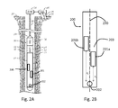
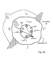
- Fig.2A shows a deployed exemplary neutron logging system in accordance with the present disclosure.
- Neutron logging tool 200 is disposed within a borehole 33 penetrating earth formation 40.
- the borehole 33 may be cased with casing 35, and the casing-borehole annulus may be filled with a grouting material such as cement.
- the borehole 33 may be an uncased open hole.
- Neutron logging tool 200 may be run decentralized or centralized to the borehole 33, and in each circumstance, the appropriate environmental corrections would be made.
- Subsection 11 of neutron logging tool 200 houses gamma ray detectors (or sensors)201a-d as well as a neutron source202.
- the detectors 201a-d are disposed at increasing longitudinal distances from the neutron generator 202, although other arrangements are possible, as discussed below.
- Neutron logging tools200 and 300 have many of the same components as discussed previously, including instrument subsection 24, telemetry subsection 26, connector 28, etc. Therefore, like reference numerals are used for the similar components, and these details are not repeated here.
- Figs.2B-2C show the side view and a top-down view of a portion of the exemplary neutron logging tool 200 with multiple detectors 201a-d (i.e., 201a, 201b, 201c, 201d) according to the present disclosure (although only two gamma ray detectors, 201a and 201b, are shown in Fig. 2B ).
- neutron source 202 which emits neutrons, may be a pulsed neutron generator or a chemical neutron source, such as an Americium-Beryllium source. While either may be used, pulsed neutron generators are preferred because they have the benefit of being electronically controlled and cycled, and also have more energetic neutrons.
- Gamma ray detectors 201a-d may be placed at different longitudinal distances ( i.e., d a , d b , etc.) from neutron source 202 along the neutron logging tool 200, as shown in Fig. 2B .
- the gamma ray detectors 201a-d may not align vertically with each other, but be dispersed radially around the circumference as shown in Fig. 2C .
- gamma ray detectors 201a-d (201d is not shown, as it is behind 201b) may also be placed at similar longitudinal distances ( i.e., d) from neutron source 202. Further details of the possible placement of the detectors 201a-d is discussed later.
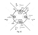
- FIG.2C shows a top-down view of the exemplary neutron logging tool 200 with multiple detectors201a-d according to the present disclosure. While Fig. 2C shows a neutron logging tool 200 with a substantially cylindrical cross-section, the neutron logging tool 200 may have a different cross-sectional shape, such as an ellipse or other shape. However, as seen from this view in Fig. 2C , multiple gamma ray detectors 201a-dare spaced about the circumference of the neutron logging tool 200. Although four detectors 201a-d are shown in Fig.
- the number of detectors in the neutron logging tool 200 may be fewer or greater.
- the gamma ray detectors 201a-d will be spaced evenly about the circumference of the neutron logging tool 200 to image different quadrants or sections of a formation 40 or a borehole 33, but an nonuniform distribution would also perform the same function.
- a greater number of gamma ray detectors 201a-d would, therefore, give greater detail for an azimuthal log.
- gamma ray detectors 201 while placed about the circumference of the neutron logging tool 200, may all be the same longitudinal distance ( d ) away from neutron source 202. This arrangement may be preferable because the detectors' individual responses can be directly compared with each other, and a correction for different distances does not have to be implemented. While not seen explicitly in Fig. 2D , it will be understood that each of gamma ray detectors 201a-d will be offset from the central axis (not shown) of the neutron logging tool 200. Accordingly, in the side view shown in Fig.
- gamma ray detector 201d (not shown) is obscured by gamma ray detector 201b.
- each tool 200 in Figs. 2A-2D has one group of detectors 201a-d, multiple sets of detectors 201a-d may be placed along the length of the tool 200 in a manner similar to the proximal detector 104, the near detector 106, the far detector 110, and the long detector 112 of the tool 10 shown in Fig. 1A .
- the detectors 201a-d can be arranged in a number of ways on the tool 200. If gamma ray detectors201a-d are spaced at different longitudinal distances from the neutron source 202, as shown in Fig. 2B , they still may be placed about the circumference of neutron logging tool 200. In such a case, the gamma ray detectors 201a-d are offset from the central axis 230 of the neutron logging tool 200, although they may still intersect central axis 230 depending on the size of the detector and the overall diameter of the tool. As an example, in the neutron logging tool 200 shown in Fig.
- gamma ray detector 201a at the top of the neutron logging tool200 may be a distance d a of 10centimeters from neutron source 202.
- the subsequent gamma ray detectors 201b, 201c, and 201d, placed at 90, 180, and 270 degrees, may be longitudinally spaced at distances of 20(d b ),30(d c ), and 40(d d ) centimeters from neutron source 202, respectively. Having gamma ray detectors 201a-d at different distances from the neutron source 202 provides the advantage of allowing for a tool with a smaller diameter.
- the gamma ray detectors may be radially overlapped but longitudinally separated to reduce the diameter of the neutron logging tool 200.
- the disadvantage is that a correction must be made for the various distances of the detectors 201a-d from the source 202, although this correction can be accounted for using techniques known in the art.
- the disclosed tool 200 with its multiple detectors 201a-d spaced around the tool's circumference at either the same or different vertical distances has shielding 203b to isolate the various detectors 201.
- Fig. 2C shows how shielding 203b can fill the core 203b of the neutron logging tool 200 to isolate the detectors 201a-d circumferentially from one another.
- Fig. 2B shows the distances d a and d b between gamma ray detectors 201a and 201b and neutron source 202.
- This spacing allows for shielding 203b between the gamma ray detectors 201a-d,providing vertical isolation in addition to horizontal isolation.
- localized shielding 203a around the detectors 201a-d can be modified.
- the shielding 203a and/or 203b effectively gives each gamma ray detector 201a-d a sensing direction (s d ), as seen in Fig. 2C .
- the sensing directions d and respective dotted lines in Fig. 2C show the discrete azimuthal directions from which the respective gamma ray detectors 201a-d detect gamma rays.
- the angle and arc of the azimuthal direction may be varied by varying the shielding around the gamma ray detectors 201a-d.
- the various detectors 201a-d may have different sensitivities.
- the differences in detector sensitivities must be resolved between the gamma ray detectors 201a-d.
- the gamma ray detectors 201a-d can be calibrated to have the same sigma ( ⁇ ) capture cross-sections, using techniques known in the art. Other normalization techniques could also be employed.
- the multiple gamma ray detectors 201a-d in the neutron logging tool 200 preferably detect gamma rays from the closest respective part of the formation. If gamma rays that passed through one side of the neutron logging tool 200 were detected by a gamma ray detector 201a-d on another side of the tool 200, an accurate azimuthal log would be difficult to generate. As such, it will be appreciated that it is preferred that each gamma ray detector 201a-d within the neutron logging tool 200 be shielded from the other detectors 201a-d.
- the core of the neutron logging tool 200 is filled (at least partially) with a shielding material 203b.
- This shielding 203b absorbs gamma rays that are released from the doped proppant or from the formation.
- shielding 203 that properly houses the detectors 201a-d can prevent gamma rays from approaching a detector 201a-d from a direction other than from the adjacent borehole wall toward the neutron logging tool's 200 center.
- shielding 203 can alter the response of the detectors 201, which can be accounted for in a particular implementation. Shielding 203 that partially surrounds a gamma ray detector 201a-d may be adjusted to optimize fracture response, optimize porosity and permeability response, and/or reduce some environmental noise-inducing effects. Shielding 203 may surround a detector both vertically as well as radially (i.e., towards the center of the neutron logging tool 200). Acceptable shielding materials may include, but are not restricted to, tungsten and lead.
- each detector 201a-d With each detector 201a-d able to read gamma rays primarily from the direction it faces, an orientation-based reading of the formation may be achieved. With a neutron logging tool 200 with multiple shielded detectors 201, each detector 201a-d will primarily detect gamma rays from the direction of the borehole 33 and formation 40 to which it is closest. As will be explained in further detail below, gamma rays may also be used to detect the presence of a doped proppant, such as a proppant doped with gadolinium. For example, the post-fracture log from a detector 201a-d in Fig.
- the 4A facing a particular direction may display a high variance from the pre-fracture baseline log for gamma ray counts at gadolinium's characteristic energy, which originates from the gadolinium being activated from the neutron source 202. This would indicate the presence of the gadolinium-doped proppant. If the pre-fracture and post-fracture logs did not display a high variance, then it might be determined that the gadolinium-doped proppant was not present. If only one detector 201a-d out of multiple detectors 201a-d displayed a high variance, it might indicate that the doped proppant within a formation fracture was not evenly distributed about the borehole 33. Accordingly, an operator analyzing the log data could make decisions, such as deciding whether additional fracturing was necessary.
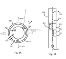
- the top down view of another embodiment of the present disclosure is shown in Fig.3A .
- the neutron logging tool 300 in Fig. 3A may have only one gamma ray detector 301, which is mounted on rotating member 320, which can rotate about the vertical central axis 330 of neutron logging tool 300.
- rotating member 320 may rotate about a different positional axis, such that the positional axis may be offset but substantially parallel to the central axis of the neutron logging tool 300.
- neutron logging tool 300 may be similar to the neutron logging tool 200shown in other figures.
- neutron logging tool 300 has a neutron source 302 and shielding 303, as shown in Fig. 3B .
- Shielding 303 may also be annular and located on rotating member 320, as shown in Fig. 3A .
- Rotating member 320 also supports rotation orientation instrument 310.
- neutron logging tool 300 also can have an orientation instrument 305 that is not on rotating member 320.
- multiple sets of rotating detectors 301 may be placed along the length of the tool 300 in a manner similar to the proximal detector 104, the near detector 106, the far detector 110, and the long detector 112 of the tool 10 shown in Fig. 1A .
- neutron logging tool 300 may have multiple rotating members 320, each with a gamma ray detector 301, spaced at increasing longitudinal distances from neutron source 302.
- one rotating member 320 may support multiple gamma ray detectors 301 at varying longitudinal distances from neutron source 302.
- Fig. 3B additionally shows actuator 321, which causes the rotation of rotating member 320, and a power source 322 to power the actuator 321.
- Actuator 321 may be an electric motor, which would rotate rotating member 320 with a gear assembly.
- Actuator 322 may also be another type of motor, such as a hydraulic motor, which would utilize hydraulic pressure to rotate rotating member 320.
- neutron logging tool 300 would have the components such as the instrumentation subsection and telemetry subsection, and further details are not provided here.
- the rotating member 320 causes the rotation of gamma ray detector 301.
- Shielding 303 can also be placed on the rotating member 320 such that the gamma ray detector 301 substantially detects gamma rays from the portion of the borehole 33 and formation 40 to which it is nearest.
- Two possible examples of general and/or localized shielding are seen in Fig. 2C , and these may be adapted to the embodiment shown in Fig. 3A . Accordingly, the gamma ray detector 301 is able to detect gamma rays from different portions of the formation 40 at different times during the rotation of the rotating member 320. For example, in Fig.
- the position of the gamma ray detector 301 allows it to detect gamma rays from a discrete azimuthal portion of the formation in the sensing direction s d , as emphasized in Fig. 3A with dotted lines. This allows the detector 301 to obtain an azimuthal reading of the formation 40 as it rotates with rotating member 320.
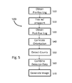
- Azimuthal logging data may be collected both before and after fracturing (steps 510, 520, and 530).
- the variance between the pre-fracture and post-fracture logs would indicate the presence of a doped proppant, as described below.
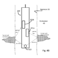
- the initial baseline pre-fracture log may be completed in multiple ways. If the borehole 33 has already been drilled, the neutron logging tool 200 may be used to take the baseline log. To capture a log with the neutron logging system, the neutron source 202 in the neutron logging tool 200 sends high energy neutrons into the surrounding formation. The neutrons quickly lose energy as the result of scattering, after which they are absorbed by the various atoms within the ambient environment. The scattered and absorbed neutrons emit gamma rays with characteristic energies, as shown in Fig. 4B . These gamma ray emissions can be measured versus characteristic energy and the presence or absence of certain materials can be determined. An example graph showing the characteristic energies of different elements is shown in Fig. 6 , where some identifiable energy peaks are labeled.
- the disclosed tool 200 has multiple detectors 201a-d disposed around the circumference of the tool 200, the detectors 201a-d capture azimuthally directed logs of portions of the borehole 33.
- the resulting pre-fracture log data obtained would essentially include log data for each detector 201, with each detector's log data logging a portion of the formation 40 ( i.e., a quadrant of the formation 40 if four detectors 201a-d are used).
- LWD logging while drilling
- Such a LWD instrument may be a different tool than the disclosed tool 200, so that some additional correlation may be needed to match the pre-fracture log obtained with the LWD tool to the post-fracture log obtained with the disclosed tool 200 (described below in step 540).
- Correlating a pre-fracture log with a post fracture log may be done by finding an orientation reference point by performing a pattern-matching technique between the two logs. In this manner, although the pre-fracture and post-fracture logs would have been obtained by separate instruments, the logs would still be able to be analyzed and compared with respect to each other.
- step 520 the borehole 33 within the formation 40 would be fractured with a proppant.
- a proppant As known in the art, wells are fractured with a fracturing fluid to treat the formation 40 and improve oil and gas production. In a standard fracturing operation, fracturing fluid is pumped down the wellbore with high pressure, causing the formation 40 to fracture around the borehole 33.
- the next stage of the fracture operation contains proppant (e.g. sand and/or other particles), which remains in the formation fractures and acts to "prop" open the fractures in the formation to increase hydrocarbon flow into the borehole 33.
- proppant e.g. sand and/or other particles
- the proppant used in the disclosed fracturing process is preferably doped with neutron-absorbing materials, such as gadolinium.
- neutron-absorbing materials may include boron, strontium, barium, gallium, manganese, tantalum, germanium, cadmium, iridium, or combinations thereof.
- a particular example of a doped proppant and its usage is shown in U.S. Patent Application Publication No. 2011/0177984 .
- the gadolinium or other material present in the doped proppant would similarly absorb neutrons that were emitted from the neutron source 202 within the neutron logging tool 200 during post-fracture logging.
- the gadolinium or other material Upon absorbing a neutron from the neutron source 202, the gadolinium or other material will become an isotope of the element.
- the isotope will subsequently release gamma rays with the characteristic energies of the isotope, which can be detected and analyzed by the gamma ray detectors 201a-d of the disclosed tool 200.
- the characteristic energies of the gamma ray emissions can be used to identify the presence or absence of these materials.
- the pre-fracture log (step 510) can be compared with the post-fracture log (step 530) to determine the effectiveness of the fracturing operation and other details consistent with the present disclosure.
- the neutron logging tool 200in wireline operations may rotate while it is lowered into the borehole 33 during the separate logs.
- the rotation of the neutron logging tool10 would not affect the resultant log.
- the neutron logging tool's 200 rotation whether inadvertent or intentional, should be compensated for to produce a more accurate azimuthal log.
- the neutron logging tool 200 may have an orientation instrument 205 (as shown in Fig. 4A ), such as electronic compass, magnetometer, inclinometer, etc., that calculates and stores orientation data.
- the orientation instrument 205 may also be a mechanical device, such as a weighting device or magnetic decentralizer that is used to ensure a particular orientation of the gamma ray detectors 201a-d.
- the placement of the instrument 205 in Fig. 4A is only meant to be illustrative; the actual placement of the instrument 205 may be elsewhere in the tool 200.
- Software navigation packs could additionally calculate the orientation of the neutron logging tool 200 as it passes downhole.
- the detector-specific logging data could then be correlated and combined with the orientation data of the neutron logging tool 200 for a given data reading, as shown in step 540 in Fig. 5 .
- These detector-specific data sets could then be combined to give azimuthal log information.
- the neutron logging tool 200 shown in Fig. 4A may have been lowered downhole via wireline with the gamma ray detector 201a (at 0 degrees) pointing north. If neutron logging tool 200 rotated such that gamma ray detector 201a (at 0 degrees) pointed east, the resulting data gathered from the gamma ray detector 201a-d would no longer be restricted to a single direction. However, the orientation instrument's 205 data could be correlated with the gamma ray detector's 201a-d data, allowing for an azimuthal log of borehole 33 that accounts for changes in the tool's 200 orientation ( i.e., rotation) in the borehole 33.
- Rotating member 320 on neutron logging tool 300 may have a rotation orientation instrument 310, which may be used to determine the position of the detector 301 as it rotates along with rotating member 320. Additionally, orientation instrument 305 may be on the non-rotating portion of the neutron logging tool 300. The orientation instrument's 305 data could be correlated with the rotation orientation instrument's 310 data, allowing for an azimuthal log of borehole 33 that accounts for changes in the tool's 300 orientation (i.e., from the rotation of the tool 300) and also accounts for the detector's 301 orientation (i.e., from the rotation of the detector 301 within the tool 300) in borehole 33.
- azimuthal log readings which incorporate a direction or orientation variable allow an operator to obtain a more accurate understanding of the acquired log data.
- Azimuthal log data may be obtained even in the case of having a horizontal borehole.
- Orientation instruments 205 are available for horizontal borehole logging as well. The data from this instrument 205 could be similarly combined with the detector log readings from the multiple detectors 201a-d as described above to create an azimuthal log of the formation.
- the pre-fracture log obtained by an LWD tool may not directly compare to the post-fracture log obtained by the neutron logging tool 200 with multiple detectors 201a-d. This is primarily because there are response differences in wireline and LWD instruments, and thus the pre- and post-fracture logs. As a result, logs taken by different instruments cannot necessarily be directly compared without additional calibration or compensation. Thus, any different response characteristics of the LWD tool and neutron logging tool 200 in the disclosed method of Fig.5 can be accounted and compensated for in order to compare logs from the different tools.
- the method can analyze the log data by counting gamma rays with respect to time, energy, total counts, and subsurface depth (or borehole distance, for example, in horizontal boreholes), (step 550), combining data from the multiple detectors 201a-d (step 560) (including orientation data), and generating a comprehensive image (step 570).
- gamma ray detectors are at different longitudinal distances from the neutron source, as shown in Fig. 2B , a correction for the different distances would have to be made when combining data at step 560.
- Time data provides information regarding formation sigma, and consequently proppant distribution.
- Gamma ray energy data, as well as total gamma ray counts, can also provide information regarding proppant distribution.
- Fig.6 displays gamma ray counts along an energy spectrum, which could be obtained by one of the detectors 201a-d of the disclosed tool 200. If a gadolinium-doped proppant is used for formation fracturing, the characteristic energy of gamma rays emitted from gadolinium could be read along the energy spectrum to detect the gadolinium's presence or absence. Gamma ray spikes for the characteristic energy for gadolinium could indicate the presence of a formation fracture with doped proppant. Variances in gamma ray counts between detectors 201a-d would indicate that the proppant was not evenly distributed within a fractured area.
- total counts of gamma rays may also be measured, without the need to separate the gamma rays along the energy spectrum. For example, if a baseline pre-fracture log has been taken of total gamma ray counts, then any significant variance in a post-fracture log from the pre-fracture log would also indicate the presence of a doped proppant. Total gamma ray counts could be analyzed with respect to time, subsurface depth, and azimuthal orientation, for example. It is understood that the total counts of gamma rays would have to be properly calibrated and/or normalized for the purposes of comparison among the detectors.
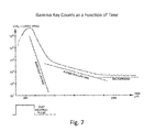
- gamma ray counts may be measured as a function of time.
- a fast neutron pulse sent from the tool's neutron source 202 would generate resultant gamma rays emissions that would have to be timely detected by a detector 201.
- the slope of the logarithmic gamma ray counts versus time can be used as an indicator to judge the sigma value of the formation 40.
- the sigma of the various detectors' formation 40 slopes can be measured. This would also allow for the detectors'201a-dgamma ray counts to be used to determine the effectiveness of the fracture of the formation 40.
- Fig.8 displays a count of gamma rays versus depth down the borehole 33 for one detector 201.
- Each detector 201a-d would generate its own set of data similar to Fig.8 , and each data set would represent gamma ray counts versus depth at the particular orientation of the detector 201a-d in the borehole 33.
- Each detector's data set may be displayed separately.
- another data set could display the sum of all or a subset of detectors' 201a-ddata sets.
Landscapes
- Physics & Mathematics (AREA)
- High Energy & Nuclear Physics (AREA)
- Life Sciences & Earth Sciences (AREA)
- General Life Sciences & Earth Sciences (AREA)
- General Physics & Mathematics (AREA)
- Geophysics (AREA)
- Geophysics And Detection Of Objects (AREA)
- Measurement Of Radiation (AREA)
Applications Claiming Priority (1)
| Application Number | Priority Date | Filing Date | Title |
|---|---|---|---|
| US201161552171P | 2011-10-27 | 2011-10-27 |
Publications (2)
| Publication Number | Publication Date |
|---|---|
| EP2615477A2 true EP2615477A2 (de) | 2013-07-17 |
| EP2615477A3 EP2615477A3 (de) | 2015-01-07 |
Family
ID=47290607
Family Applications (1)
| Application Number | Title | Priority Date | Filing Date |
|---|---|---|---|
| EP12190458.5A Withdrawn EP2615477A3 (de) | 2011-10-27 | 2012-10-29 | Neutronenerfassungswerkzeug mit mehreren Detektoren |
Country Status (5)
| Country | Link |
|---|---|
| US (1) | US9012836B2 (de) |
| EP (1) | EP2615477A3 (de) |
| AU (2) | AU2012244198B2 (de) |
| BR (1) | BR102012027741A8 (de) |
| CA (1) | CA2793472C (de) |
Cited By (1)
| Publication number | Priority date | Publication date | Assignee | Title |
|---|---|---|---|---|
| US10036828B2 (en) | 2014-01-02 | 2018-07-31 | Shell Oil Company | System and method for making downhole measurements |
Families Citing this family (36)
| Publication number | Priority date | Publication date | Assignee | Title |
|---|---|---|---|---|
| US9268056B2 (en) * | 2012-03-28 | 2016-02-23 | Schlumberger Technology Corporation | Neutron porosity based on one or more gamma ray detectors and a pulsed neutron source |
| US10379253B2 (en) | 2013-05-15 | 2019-08-13 | Schlumberger Technology Corporation | Borehole fluid effect correction for pulsed neutron porosity measurements |
| WO2014190439A1 (en) | 2013-05-31 | 2014-12-04 | Evolution Engineering Inc. | Downhole pocket electronics |
| BR112014026113A2 (pt) | 2013-06-14 | 2017-07-18 | Reme Tech Llc | conjunto de controlador gama múltiplo |
| EP2972520A4 (de) * | 2013-06-14 | 2016-12-14 | Reme Llc | Anordnung zur erkennung des gesundheitszustandes von gamma-sonden |
| US10564311B2 (en) | 2013-09-30 | 2020-02-18 | Schlumberger Technology Corporation | Formation imaging using neutron activation |
| US9310515B2 (en) | 2014-03-21 | 2016-04-12 | Schlumberger Technology Corporation | Method for using neutron interaction cross section to interpret neutron measurements |
| US9890632B2 (en) * | 2014-06-20 | 2018-02-13 | Saudi Arabian Oil Company | Systems, computer medium and computer-implemented methods for logging using a logging tool with adjustable detectors |
| US9864092B2 (en) * | 2014-06-26 | 2018-01-09 | Board Of Regents, The University Of Texas System | Tracers for formation analysis |
| US10466383B2 (en) | 2015-05-29 | 2019-11-05 | Schlumberger Technology Corporation | Method for using neutron interaction cross section to interpret neutron measurements |
| US9995842B2 (en) | 2015-05-29 | 2018-06-12 | Schlumberger Technology Corporation | Borehole fluid and/or casing effect correction for pulsed neutron measurements |
| EP3337952A4 (de) | 2015-11-05 | 2018-09-12 | Halliburton Energy Services, Inc. | Kombinierte radioaktive quelle für gamma-neutronen-instrument |
| US10001582B2 (en) | 2016-02-04 | 2018-06-19 | Schlumberger Technology Corporation | Method for using pulsed neutron induced gamma ray measurements to determine formation properties |
| US10436933B2 (en) | 2016-05-06 | 2019-10-08 | Baker Hughes, A Ge Company, Llc | Digital spectrometer for measuring ironizing radiation downhole |
| MX2019009320A (es) * | 2017-02-08 | 2019-12-11 | teague Philip | Métodos y medios para la obtención de imágenes de porosidad azimutal de neutrones de volúmenes de formación y cemento que rodean un pozo. |
| US9863895B1 (en) | 2017-02-22 | 2018-01-09 | Saudi Arabian Oil Company | Systems and methods for monitoring casing cement integrity |
| US10677958B2 (en) | 2017-02-24 | 2020-06-09 | Visuray Intech Ltd (Bvi) | Resolution of detection of an azimuthal distribution of materials in multi-casing wellbore environments |
| AU2018225203B2 (en) | 2017-02-27 | 2021-07-01 | Alex Stewart | Detecting anomalies in annular materials of single and dual casing string environments |
| US10254437B2 (en) | 2017-04-12 | 2019-04-09 | Visuray Intech Ltd (Bvi) | Temperature performance of a scintillator-based radiation detector system |
| BR112019023219A2 (pt) | 2017-06-20 | 2020-08-18 | Halliburton Energy Services, Inc. | ferramenta de imagem de fundo de poço não rotativa, sistema de geração de imagens para um furo de poço e método para determinar informações associadas a um furo de poço |
| US20190018166A1 (en) * | 2017-09-06 | 2019-01-17 | Philip Teague | Real-time output correction of detector outputs resulting from azimuthal x-ray source variations using monitoring detectors |
| AU2018352730B2 (en) | 2017-10-17 | 2021-05-27 | Alex Stewart | Methods and means for simultaneous casing integrity evaluation and cement inspection in a multiple-casing wellbore environment |
| WO2019079429A1 (en) | 2017-10-18 | 2019-04-25 | Philip Teague | METHODS AND MEANS FOR EVALUATING TUBING, PUNCHING AND SAND CLAW USING X-RAY RADIATION RETROSPRATED IN A WELLBORE ENVIRONMENT |
| EP3698180A1 (de) | 2017-10-19 | 2020-08-26 | Philip Teague | Verfahren und mittel zur rohrtourintegritätsbeurteilung unter verwendung von rückgestreuter röntgenstrahlung in einer bohrlochumgebung |
| AU2018355216A1 (en) | 2017-10-23 | 2020-06-04 | Philip Teague | Methods and means for determining the existence of cement debonding within a cased borehole using x-ray techniques |
| US10705247B2 (en) | 2017-11-22 | 2020-07-07 | Visuray Intech Ltd (Bvi) | Methods and means for fracture mapping in a well bore |
| US10466384B2 (en) | 2018-01-02 | 2019-11-05 | Weatherford Technology Holdings, Llc | Techniques for determining formation composition from measured nuclear spectra |
| US20190187325A1 (en) | 2018-02-14 | 2019-06-20 | Philip Teague | Methods and means for neutron imaging within a borehole |
| AU2019262636B2 (en) | 2018-05-03 | 2022-10-20 | Dimitrios Pirovolou | Methods and means for evaluating and monitoring formation creep and shale barriers using ionizing radiation |
| US11078783B2 (en) | 2019-05-24 | 2021-08-03 | Weatherford Technology Holdings, Llc | Caliper-behind-casing from pulsed neutron apparatus |
| CN110136860B (zh) * | 2019-05-25 | 2024-08-27 | 广东太微加速器有限公司 | 一种快中子筛选装置及筛选方法 |
| US11163089B2 (en) * | 2019-07-26 | 2021-11-02 | Schlumberger Technology Corporation | Neutron imaging devices for cased wells and open boreholes |
| US11906692B2 (en) | 2021-02-11 | 2024-02-20 | China Petroleum & Chemical Corporation | Nuclear logging tools and applications thereof |
| US12196911B2 (en) | 2021-02-11 | 2025-01-14 | China Petroleum & Chemical Corporation | Method and apparatus for obtaining real-time downhole oil saturation |
| US12504556B2 (en) | 2021-02-11 | 2025-12-23 | China Petroleum & Chemical Corporation | Method and apparatus for obtaining formation density |
| US11573350B1 (en) | 2021-09-13 | 2023-02-07 | Weatherford Technology Holdings, Llc | Pulsed neutron logging tool with in-air automatic shutdown |
Citations (4)
| Publication number | Priority date | Publication date | Assignee | Title |
|---|---|---|---|---|
| US5374823A (en) | 1993-10-28 | 1994-12-20 | Computalog U.S.A., Inc. | Pulsed neutron decay tool for measuring gamma radiation energy spectra for fast neutron inelastic collisions and thermal neutron capture events |
| US6376838B1 (en) | 1998-03-06 | 2002-04-23 | Computalog Usa, Inc. | Formation evaluation combination system for petrophysical well log analysis |
| US20110177984A1 (en) | 2004-04-05 | 2011-07-21 | Carbo Ceramics Inc. | Tagged Propping Agents and Related Methods |
| US7999220B2 (en) | 2008-05-30 | 2011-08-16 | Precision Energy Services, Inc. | Borehole measurements using a fast and high energy resolution gamma ray detector assembly |
Family Cites Families (35)
| Publication number | Priority date | Publication date | Assignee | Title |
|---|---|---|---|---|
| US4415035A (en) * | 1982-03-18 | 1983-11-15 | Mobil Oil Corporation | Method for fracturing a plurality of subterranean formations |
| US4549608A (en) * | 1984-07-12 | 1985-10-29 | Mobil Oil Corporation | Hydraulic fracturing method employing special sand control technique |
| US4780857A (en) * | 1987-12-02 | 1988-10-25 | Mobil Oil Corporation | Method for logging the characteristics of materials forming the walls of a borehole |
| US5044462A (en) * | 1990-07-31 | 1991-09-03 | Halliburton Logging Services, Inc. | Focused planar transducer |
| US5018578A (en) * | 1990-08-06 | 1991-05-28 | Halliburton Company | Method of arresting hydraulic fracture propagation |
| US5318123A (en) * | 1992-06-11 | 1994-06-07 | Halliburton Company | Method for optimizing hydraulic fracturing through control of perforation orientation |
| US5322126A (en) * | 1993-04-16 | 1994-06-21 | The Energex Company | System and method for monitoring fracture growth during hydraulic fracture treatment |
| US5363919A (en) * | 1993-11-15 | 1994-11-15 | Mobil Oil Corporation | Simultaneous hydraulic fracturing using fluids with different densities |
| US6300624B1 (en) * | 1999-03-25 | 2001-10-09 | Halliburton Energy Services, Inc. | Radiation detector |
| US6508307B1 (en) * | 1999-07-22 | 2003-01-21 | Schlumberger Technology Corporation | Techniques for hydraulic fracturing combining oriented perforating and low viscosity fluids |
| US6566649B1 (en) * | 2000-05-26 | 2003-05-20 | Precision Drilling Technology Services Group Inc. | Standoff compensation for nuclear measurements |
| US6590202B2 (en) * | 2000-05-26 | 2003-07-08 | Precision Drilling Technology Services Group Inc. | Standoff compensation for nuclear measurements |
| US6700115B2 (en) * | 2000-05-26 | 2004-03-02 | Precision Drilling Technology Services Group Inc. | Standoff compensation for nuclear measurements |
| US6552333B1 (en) * | 2000-08-16 | 2003-04-22 | Halliburton Energy Services, Inc. | Apparatus and methods for determining gravel pack quality |
| US6781115B2 (en) * | 2001-03-30 | 2004-08-24 | Schlumberger Technology Corporation | Subsurface radiation phenomena detection with combined and azimuthally sensitive detectors |
| US20060048937A1 (en) * | 2004-09-09 | 2006-03-09 | Pinto C J | Perforation method and apparatus |
| US6944548B2 (en) * | 2002-12-30 | 2005-09-13 | Schlumberger Technology Corporation | Formation evaluation through azimuthal measurements |
| US7204308B2 (en) * | 2004-03-04 | 2007-04-17 | Halliburton Energy Services, Inc. | Borehole marking devices and methods |
| US7225869B2 (en) * | 2004-03-24 | 2007-06-05 | Halliburton Energy Services, Inc. | Methods of isolating hydrajet stimulated zones |
| US20060131016A1 (en) * | 2004-06-12 | 2006-06-22 | Ivan Snoga | Apparatus and method for determining the dip of an underground formation in a cased or uncased borehole |
| CA2618128C (en) * | 2005-08-09 | 2012-10-09 | Hexion Specialty Chemicals, Inc. | Methods and compositions for determination of fracture geometry in subterranean formations |
| US7279677B2 (en) * | 2005-08-22 | 2007-10-09 | Schlumberger Technology Corporation | Measuring wellbore diameter with an LWD instrument using compton and photoelectric effects |
| US7482578B2 (en) * | 2006-06-12 | 2009-01-27 | Lonkar Services, Ltd. | Gamma radiation spectral logging system and method for processing gamma radiation spectra |
| US7933718B2 (en) * | 2006-08-09 | 2011-04-26 | Momentive Specialty Chemicals Inc. | Method and tool for determination of fracture geometry in subterranean formations based on in-situ neutron activation analysis |
| US7966874B2 (en) * | 2006-09-28 | 2011-06-28 | Baker Hughes Incorporated | Multi-resolution borehole profiling |
| US7942201B2 (en) * | 2007-05-11 | 2011-05-17 | Clearwater International, Llc | Apparatus, compositions, and methods of breaking fracturing fluids |
| GB2466901B (en) | 2007-11-07 | 2012-10-24 | Baker Hughes Inc | Azimuthal elemental imaging |
| US8214151B2 (en) * | 2008-02-20 | 2012-07-03 | Carbo Ceramics Inc. | Methods of identifying high neutron capture cross section doped proppant in induced subterranean formation fractures |
| US7544929B1 (en) * | 2008-05-13 | 2009-06-09 | Precision Energy Services, Inc. | Borehole imaging and standoff determination using neutron measurements |
| EP2120066B1 (de) * | 2008-05-16 | 2012-08-29 | Services Pétroliers Schlumberger | Neutronenabschirmung für ein Bohrlochinstrument |
| WO2011014538A2 (en) * | 2009-07-30 | 2011-02-03 | Baker Hughes Incorporated | Gamma ray detectors having azimuthal sensitivity |
| US7975541B2 (en) * | 2009-12-16 | 2011-07-12 | General Electric Company | Folding ultrasonic borehole imaging tool |
| US9031790B2 (en) * | 2010-03-23 | 2015-05-12 | Schlumberger Technology Corporation | System and method for correction of borehole effects in a neutron porosity measurement |
| US8365827B2 (en) * | 2010-06-16 | 2013-02-05 | Baker Hughes Incorporated | Fracturing method to reduce tortuosity |
| US8664587B2 (en) * | 2010-11-19 | 2014-03-04 | Schlumberger Technology Corporation | Non-rotating logging-while-drilling neutron imaging tool |
-
2012
- 2012-10-26 US US13/661,764 patent/US9012836B2/en active Active
- 2012-10-26 CA CA2793472A patent/CA2793472C/en not_active Expired - Fee Related
- 2012-10-29 BR BR102012027741A patent/BR102012027741A8/pt not_active IP Right Cessation
- 2012-10-29 AU AU2012244198A patent/AU2012244198B2/en not_active Ceased
- 2012-10-29 EP EP12190458.5A patent/EP2615477A3/de not_active Withdrawn
-
2014
- 2014-08-06 AU AU2014210585A patent/AU2014210585B2/en not_active Ceased
Patent Citations (4)
| Publication number | Priority date | Publication date | Assignee | Title |
|---|---|---|---|---|
| US5374823A (en) | 1993-10-28 | 1994-12-20 | Computalog U.S.A., Inc. | Pulsed neutron decay tool for measuring gamma radiation energy spectra for fast neutron inelastic collisions and thermal neutron capture events |
| US6376838B1 (en) | 1998-03-06 | 2002-04-23 | Computalog Usa, Inc. | Formation evaluation combination system for petrophysical well log analysis |
| US20110177984A1 (en) | 2004-04-05 | 2011-07-21 | Carbo Ceramics Inc. | Tagged Propping Agents and Related Methods |
| US7999220B2 (en) | 2008-05-30 | 2011-08-16 | Precision Energy Services, Inc. | Borehole measurements using a fast and high energy resolution gamma ray detector assembly |
Non-Patent Citations (1)
| Title |
|---|
| PEMPER ET AL.: "Hydraulic fracture evaluation with multiple radioactive tracers", GEOPHYSICS, vol. 53, no. 10, October 1998 (1998-10-01), pages 1323 - 1333 |
Cited By (1)
| Publication number | Priority date | Publication date | Assignee | Title |
|---|---|---|---|---|
| US10036828B2 (en) | 2014-01-02 | 2018-07-31 | Shell Oil Company | System and method for making downhole measurements |
Also Published As
| Publication number | Publication date |
|---|---|
| CA2793472C (en) | 2015-12-15 |
| US20130105678A1 (en) | 2013-05-02 |
| BR102012027741A2 (pt) | 2014-03-04 |
| US9012836B2 (en) | 2015-04-21 |
| EP2615477A3 (de) | 2015-01-07 |
| AU2012244198B2 (en) | 2014-06-05 |
| AU2014210585A1 (en) | 2014-08-28 |
| CA2793472A1 (en) | 2013-04-27 |
| BR102012027741A8 (pt) | 2017-03-01 |
| AU2012244198A1 (en) | 2013-05-16 |
| AU2014210585B2 (en) | 2015-07-30 |
Similar Documents
| Publication | Publication Date | Title |
|---|---|---|
| AU2014210585B2 (en) | Neutron logging tool with multiple detectors | |
| US9267359B2 (en) | Method and apparatus for interrogating a subterranean annulus | |
| US20100017134A1 (en) | Gravel pack assessment tool and methods of use | |
| US9575206B2 (en) | Downhole evaluation with neutron activation measurement | |
| WO2014190244A1 (en) | Well-logging tool with azimuthal and spectral radiation detectors and related methods | |
| US10941653B2 (en) | Apparatus, system, and method for downhole imaging using a non-rotatable imaging tool having a radiation detector | |
| US20140291500A1 (en) | Method for Evaluating Voids in a Subterranean Formation | |
| US20200096668A1 (en) | Methods and means for azimuthal neutron porosity imaging of formation and cement volumes surrounding a borehole | |
| US20140346337A1 (en) | Well-Logging Tool With First And Second Azimuthal Radiation Detectors And Related Methods | |
| EP3455461B1 (de) | Verfahren zur bohrlochmessung und näherungserkennung | |
| GB2497857A (en) | Investigating a subterranean annulus using a radiation detector to identify a substance | |
| EP2904433B1 (de) | Verfahren zur detektierung von brüchen in einer unterirdischen formation | |
| WO2015195552A1 (en) | Method for evaluating voids in a subterranean formation | |
| US11275195B2 (en) | Methods and means for azimuthal neutron porosity imaging of formation and cement volumes surrounding a borehole |
Legal Events
| Date | Code | Title | Description |
|---|---|---|---|
| PUAI | Public reference made under article 153(3) epc to a published international application that has entered the european phase |
Free format text: ORIGINAL CODE: 0009012 |
|
| 17P | Request for examination filed |
Effective date: 20121029 |
|
| AK | Designated contracting states |
Kind code of ref document: A2 Designated state(s): AL AT BE BG CH CY CZ DE DK EE ES FI FR GB GR HR HU IE IS IT LI LT LU LV MC MK MT NL NO PL PT RO RS SE SI SK SM TR |
|
| AX | Request for extension of the european patent |
Extension state: BA ME |
|
| RAP1 | Party data changed (applicant data changed or rights of an application transferred) |
Owner name: WEATHERFORD/LAMB, INC. |
|
| PUAL | Search report despatched |
Free format text: ORIGINAL CODE: 0009013 |
|
| AK | Designated contracting states |
Kind code of ref document: A3 Designated state(s): AL AT BE BG CH CY CZ DE DK EE ES FI FR GB GR HR HU IE IS IT LI LT LU LV MC MK MT NL NO PL PT RO RS SE SI SK SM TR |
|
| AX | Request for extension of the european patent |
Extension state: BA ME |
|
| RIC1 | Information provided on ipc code assigned before grant |
Ipc: G01V 5/10 20060101AFI20141128BHEP |
|
| RAP1 | Party data changed (applicant data changed or rights of an application transferred) |
Owner name: WEATHERFORD TECHNOLOGY HOLDINGS, LLC |
|
| RBV | Designated contracting states (corrected) |
Designated state(s): AL AT BE BG CH CY CZ DE DK EE ES FI FR GB GR HR HU IE IS IT LI LT LU LV MC MK MT NL NO PL PT RO RS SE SI SK SM TR |
|
| STAA | Information on the status of an ep patent application or granted ep patent |
Free format text: STATUS: EXAMINATION IS IN PROGRESS |
|
| 17Q | First examination report despatched |
Effective date: 20170227 |
|
| GRAP | Despatch of communication of intention to grant a patent |
Free format text: ORIGINAL CODE: EPIDOSNIGR1 |
|
| STAA | Information on the status of an ep patent application or granted ep patent |
Free format text: STATUS: GRANT OF PATENT IS INTENDED |
|
| INTG | Intention to grant announced |
Effective date: 20181019 |
|
| STAA | Information on the status of an ep patent application or granted ep patent |
Free format text: STATUS: THE APPLICATION IS DEEMED TO BE WITHDRAWN |
|
| 18D | Application deemed to be withdrawn |
Effective date: 20190301 |