EP2615250A1 - Continuous fiber reinforced mesh bond coat for environmental barrier coating system - Google Patents
Continuous fiber reinforced mesh bond coat for environmental barrier coating system Download PDFInfo
- Publication number
- EP2615250A1 EP2615250A1 EP13150246.0A EP13150246A EP2615250A1 EP 2615250 A1 EP2615250 A1 EP 2615250A1 EP 13150246 A EP13150246 A EP 13150246A EP 2615250 A1 EP2615250 A1 EP 2615250A1
- Authority
- EP
- European Patent Office
- Prior art keywords
- gas turbine
- bond layer
- porous substrate
- layer
- fiber mesh
- Prior art date
- Legal status (The legal status is an assumption and is not a legal conclusion. Google has not performed a legal analysis and makes no representation as to the accuracy of the status listed.)
- Granted
Links
- 239000000835 fiber Substances 0.000 title claims abstract description 97
- 238000000576 coating method Methods 0.000 title claims description 12
- 230000004888 barrier function Effects 0.000 title claims description 8
- 239000011248 coating agent Substances 0.000 title claims description 7
- 230000007613 environmental effect Effects 0.000 title claims description 5
- 239000010410 layer Substances 0.000 claims abstract description 111
- 239000000758 substrate Substances 0.000 claims abstract description 25
- 239000011241 protective layer Substances 0.000 claims abstract description 11
- 238000000034 method Methods 0.000 claims description 11
- 239000000919 ceramic Substances 0.000 claims description 5
- 239000013078 crystal Substances 0.000 claims description 2
- 150000001247 metal acetylides Chemical class 0.000 claims description 2
- 150000004767 nitrides Chemical class 0.000 claims description 2
- 239000007789 gas Substances 0.000 description 41
- 239000012530 fluid Substances 0.000 description 16
- 239000000463 material Substances 0.000 description 12
- 239000011153 ceramic matrix composite Substances 0.000 description 4
- 238000002485 combustion reaction Methods 0.000 description 4
- GWEVSGVZZGPLCZ-UHFFFAOYSA-N Titan oxide Chemical compound O=[Ti]=O GWEVSGVZZGPLCZ-UHFFFAOYSA-N 0.000 description 2
- MCMNRKCIXSYSNV-UHFFFAOYSA-N Zirconium dioxide Chemical compound O=[Zr]=O MCMNRKCIXSYSNV-UHFFFAOYSA-N 0.000 description 2
- PNEYBMLMFCGWSK-UHFFFAOYSA-N aluminium oxide Inorganic materials [O-2].[O-2].[O-2].[Al+3].[Al+3] PNEYBMLMFCGWSK-UHFFFAOYSA-N 0.000 description 2
- JNDMLEXHDPKVFC-UHFFFAOYSA-N aluminum;oxygen(2-);yttrium(3+) Chemical compound [O-2].[O-2].[O-2].[Al+3].[Y+3] JNDMLEXHDPKVFC-UHFFFAOYSA-N 0.000 description 2
- 238000005229 chemical vapour deposition Methods 0.000 description 2
- KZHJGOXRZJKJNY-UHFFFAOYSA-N dioxosilane;oxo(oxoalumanyloxy)alumane Chemical compound O=[Si]=O.O=[Si]=O.O=[Al]O[Al]=O.O=[Al]O[Al]=O.O=[Al]O[Al]=O KZHJGOXRZJKJNY-UHFFFAOYSA-N 0.000 description 2
- 229910052751 metal Inorganic materials 0.000 description 2
- 239000002184 metal Substances 0.000 description 2
- 230000000116 mitigating effect Effects 0.000 description 2
- 229910052863 mullite Inorganic materials 0.000 description 2
- 230000003647 oxidation Effects 0.000 description 2
- 238000007254 oxidation reaction Methods 0.000 description 2
- 238000000623 plasma-assisted chemical vapour deposition Methods 0.000 description 2
- 230000002787 reinforcement Effects 0.000 description 2
- 229910052710 silicon Inorganic materials 0.000 description 2
- 239000010703 silicon Substances 0.000 description 2
- 229910019901 yttrium aluminum garnet Inorganic materials 0.000 description 2
- 229910052580 B4C Inorganic materials 0.000 description 1
- 229910052582 BN Inorganic materials 0.000 description 1
- PZNSFCLAULLKQX-UHFFFAOYSA-N Boron nitride Chemical compound N#B PZNSFCLAULLKQX-UHFFFAOYSA-N 0.000 description 1
- NPXOKRUENSOPAO-UHFFFAOYSA-N Raney nickel Chemical compound [Al].[Ni] NPXOKRUENSOPAO-UHFFFAOYSA-N 0.000 description 1
- 229910052581 Si3N4 Inorganic materials 0.000 description 1
- XUIMIQQOPSSXEZ-UHFFFAOYSA-N Silicon Chemical compound [Si] XUIMIQQOPSSXEZ-UHFFFAOYSA-N 0.000 description 1
- OQPDWFJSZHWILH-UHFFFAOYSA-N [Al].[Al].[Al].[Ti] Chemical compound [Al].[Al].[Al].[Ti] OQPDWFJSZHWILH-UHFFFAOYSA-N 0.000 description 1
- 230000001133 acceleration Effects 0.000 description 1
- 230000001464 adherent effect Effects 0.000 description 1
- QVGXLLKOCUKJST-UHFFFAOYSA-N atomic oxygen Chemical compound [O] QVGXLLKOCUKJST-UHFFFAOYSA-N 0.000 description 1
- YXTPWUNVHCYOSP-UHFFFAOYSA-N bis($l^{2}-silanylidene)molybdenum Chemical compound [Si]=[Mo]=[Si] YXTPWUNVHCYOSP-UHFFFAOYSA-N 0.000 description 1
- INAHAJYZKVIDIZ-UHFFFAOYSA-N boron carbide Chemical compound B12B3B4C32B41 INAHAJYZKVIDIZ-UHFFFAOYSA-N 0.000 description 1
- 238000001816 cooling Methods 0.000 description 1
- 238000005336 cracking Methods 0.000 description 1
- 238000000151 deposition Methods 0.000 description 1
- 230000008021 deposition Effects 0.000 description 1
- 238000003618 dip coating Methods 0.000 description 1
- 230000000694 effects Effects 0.000 description 1
- 238000000605 extraction Methods 0.000 description 1
- 239000011521 glass Substances 0.000 description 1
- 229910000765 intermetallic Inorganic materials 0.000 description 1
- CPLXHLVBOLITMK-UHFFFAOYSA-N magnesium oxide Inorganic materials [Mg]=O CPLXHLVBOLITMK-UHFFFAOYSA-N 0.000 description 1
- 239000000395 magnesium oxide Substances 0.000 description 1
- AXZKOIWUVFPNLO-UHFFFAOYSA-N magnesium;oxygen(2-) Chemical compound [O-2].[Mg+2] AXZKOIWUVFPNLO-UHFFFAOYSA-N 0.000 description 1
- 238000002844 melting Methods 0.000 description 1
- 230000008018 melting Effects 0.000 description 1
- 150000002739 metals Chemical class 0.000 description 1
- 239000000203 mixture Substances 0.000 description 1
- 229910021343 molybdenum disilicide Inorganic materials 0.000 description 1
- 229910000907 nickel aluminide Inorganic materials 0.000 description 1
- 239000001301 oxygen Substances 0.000 description 1
- 229910052760 oxygen Inorganic materials 0.000 description 1
- 238000010248 power generation Methods 0.000 description 1
- 230000002265 prevention Effects 0.000 description 1
- 229910010271 silicon carbide Inorganic materials 0.000 description 1
- HBMJWWWQQXIZIP-UHFFFAOYSA-N silicon carbide Chemical compound [Si+]#[C-] HBMJWWWQQXIZIP-UHFFFAOYSA-N 0.000 description 1
- HQVNEWCFYHHQES-UHFFFAOYSA-N silicon nitride Chemical compound N12[Si]34N5[Si]62N3[Si]51N64 HQVNEWCFYHHQES-UHFFFAOYSA-N 0.000 description 1
- 229910052596 spinel Inorganic materials 0.000 description 1
- 239000011029 spinel Substances 0.000 description 1
- 239000007921 spray Substances 0.000 description 1
- 239000000126 substance Substances 0.000 description 1
- 229910021324 titanium aluminide Inorganic materials 0.000 description 1
- MTPVUVINMAGMJL-UHFFFAOYSA-N trimethyl(1,1,2,2,2-pentafluoroethyl)silane Chemical compound C[Si](C)(C)C(F)(F)C(F)(F)F MTPVUVINMAGMJL-UHFFFAOYSA-N 0.000 description 1
- XLYOFNOQVPJJNP-UHFFFAOYSA-N water Chemical compound O XLYOFNOQVPJJNP-UHFFFAOYSA-N 0.000 description 1
Images


Classifications
-
- F—MECHANICAL ENGINEERING; LIGHTING; HEATING; WEAPONS; BLASTING
- F01—MACHINES OR ENGINES IN GENERAL; ENGINE PLANTS IN GENERAL; STEAM ENGINES
- F01D—NON-POSITIVE DISPLACEMENT MACHINES OR ENGINES, e.g. STEAM TURBINES
- F01D5/00—Blades; Blade-carrying members; Heating, heat-insulating, cooling or antivibration means on the blades or the members
- F01D5/12—Blades
- F01D5/28—Selecting particular materials; Particular measures relating thereto; Measures against erosion or corrosion
- F01D5/288—Protective coatings for blades
-
- C—CHEMISTRY; METALLURGY
- C04—CEMENTS; CONCRETE; ARTIFICIAL STONE; CERAMICS; REFRACTORIES
- C04B—LIME, MAGNESIA; SLAG; CEMENTS; COMPOSITIONS THEREOF, e.g. MORTARS, CONCRETE OR LIKE BUILDING MATERIALS; ARTIFICIAL STONE; CERAMICS; REFRACTORIES; TREATMENT OF NATURAL STONE
- C04B41/00—After-treatment of mortars, concrete, artificial stone or ceramics; Treatment of natural stone
- C04B41/009—After-treatment of mortars, concrete, artificial stone or ceramics; Treatment of natural stone characterised by the material treated
-
- C—CHEMISTRY; METALLURGY
- C04—CEMENTS; CONCRETE; ARTIFICIAL STONE; CERAMICS; REFRACTORIES
- C04B—LIME, MAGNESIA; SLAG; CEMENTS; COMPOSITIONS THEREOF, e.g. MORTARS, CONCRETE OR LIKE BUILDING MATERIALS; ARTIFICIAL STONE; CERAMICS; REFRACTORIES; TREATMENT OF NATURAL STONE
- C04B41/00—After-treatment of mortars, concrete, artificial stone or ceramics; Treatment of natural stone
- C04B41/45—Coating or impregnating, e.g. injection in masonry, partial coating of green or fired ceramics, organic coating compositions for adhering together two concrete elements
- C04B41/52—Multiple coating or impregnating multiple coating or impregnating with the same composition or with compositions only differing in the concentration of the constituents, is classified as single coating or impregnation
-
- C—CHEMISTRY; METALLURGY
- C04—CEMENTS; CONCRETE; ARTIFICIAL STONE; CERAMICS; REFRACTORIES
- C04B—LIME, MAGNESIA; SLAG; CEMENTS; COMPOSITIONS THEREOF, e.g. MORTARS, CONCRETE OR LIKE BUILDING MATERIALS; ARTIFICIAL STONE; CERAMICS; REFRACTORIES; TREATMENT OF NATURAL STONE
- C04B41/00—After-treatment of mortars, concrete, artificial stone or ceramics; Treatment of natural stone
- C04B41/80—After-treatment of mortars, concrete, artificial stone or ceramics; Treatment of natural stone of only ceramics
- C04B41/81—Coating or impregnation
- C04B41/89—Coating or impregnation for obtaining at least two superposed coatings having different compositions
-
- F—MECHANICAL ENGINEERING; LIGHTING; HEATING; WEAPONS; BLASTING
- F05—INDEXING SCHEMES RELATING TO ENGINES OR PUMPS IN VARIOUS SUBCLASSES OF CLASSES F01-F04
- F05D—INDEXING SCHEME FOR ASPECTS RELATING TO NON-POSITIVE-DISPLACEMENT MACHINES OR ENGINES, GAS-TURBINES OR JET-PROPULSION PLANTS
- F05D2230/00—Manufacture
- F05D2230/90—Coating; Surface treatment
-
- F—MECHANICAL ENGINEERING; LIGHTING; HEATING; WEAPONS; BLASTING
- F05—INDEXING SCHEMES RELATING TO ENGINES OR PUMPS IN VARIOUS SUBCLASSES OF CLASSES F01-F04
- F05D—INDEXING SCHEME FOR ASPECTS RELATING TO NON-POSITIVE-DISPLACEMENT MACHINES OR ENGINES, GAS-TURBINES OR JET-PROPULSION PLANTS
- F05D2300/00—Materials; Properties thereof
- F05D2300/20—Oxide or non-oxide ceramics
-
- F—MECHANICAL ENGINEERING; LIGHTING; HEATING; WEAPONS; BLASTING
- F05—INDEXING SCHEMES RELATING TO ENGINES OR PUMPS IN VARIOUS SUBCLASSES OF CLASSES F01-F04
- F05D—INDEXING SCHEME FOR ASPECTS RELATING TO NON-POSITIVE-DISPLACEMENT MACHINES OR ENGINES, GAS-TURBINES OR JET-PROPULSION PLANTS
- F05D2300/00—Materials; Properties thereof
- F05D2300/60—Properties or characteristics given to material by treatment or manufacturing
- F05D2300/603—Composites; e.g. fibre-reinforced
- F05D2300/6034—Orientation of fibres, weaving, ply angle
-
- F—MECHANICAL ENGINEERING; LIGHTING; HEATING; WEAPONS; BLASTING
- F05—INDEXING SCHEMES RELATING TO ENGINES OR PUMPS IN VARIOUS SUBCLASSES OF CLASSES F01-F04
- F05D—INDEXING SCHEME FOR ASPECTS RELATING TO NON-POSITIVE-DISPLACEMENT MACHINES OR ENGINES, GAS-TURBINES OR JET-PROPULSION PLANTS
- F05D2300/00—Materials; Properties thereof
- F05D2300/60—Properties or characteristics given to material by treatment or manufacturing
- F05D2300/614—Fibres or filaments
-
- Y—GENERAL TAGGING OF NEW TECHNOLOGICAL DEVELOPMENTS; GENERAL TAGGING OF CROSS-SECTIONAL TECHNOLOGIES SPANNING OVER SEVERAL SECTIONS OF THE IPC; TECHNICAL SUBJECTS COVERED BY FORMER USPC CROSS-REFERENCE ART COLLECTIONS [XRACs] AND DIGESTS
- Y02—TECHNOLOGIES OR APPLICATIONS FOR MITIGATION OR ADAPTATION AGAINST CLIMATE CHANGE
- Y02T—CLIMATE CHANGE MITIGATION TECHNOLOGIES RELATED TO TRANSPORTATION
- Y02T50/00—Aeronautics or air transport
- Y02T50/60—Efficient propulsion technologies, e.g. for aircraft
Definitions
- the present disclosure relates to gas turbine blades and in particular to creep resistant coating systems for gas turbine blades.
- Gas turbines which may also be referred to as combustion turbines, are internal combustion engines that accelerate gases, forcing the gases into a combustion chamber where heat is added to increase the volume of the gases. The expanded gases are then directed towards a turbine to extract the energy generated by the expanded gases. Gas turbines have many practical applications, including usage as jet engines and in industrial power generation systems.
- the acceleration and directing of gases within a gas turbine are often accomplished using rotating blades. Extraction of energy is typically accomplished by forcing expanded gases from the combustion chamber towards gas turbine blades that are spun by the force of the expanded gases exiting the gas turbine through the turbine blades. Due to the high temperatures of the exiting gases, gas turbine blades must be constructed to endure extreme operating conditions. In many systems, complex turbine blade cooling systems are employed. While gas turbine blades are commonly constructed from metals, more advanced materials are now being used for such blades, such as ceramics and ceramic matrix composites. When using such advanced materials or simply metal in constructing gas turbine blades, coatings may be applied to provide added protection to the blades and increased heat resistance.
- a gas turbine blade having a surface and a bond layer applied to the surface.
- a porous substrate may be applied to the bond layer and one or more protective layers may be applied to the bond layer such that the porous substrate is embedded between the bond layer and the protective layers to prevent and mitigate creep.
- a method for mitigating and preventing creep may be disclosed.
- a bond layer may be applied to a surface of a gas turbine blade and a porous substrate may be applied to the bond layer.
- One or more protective layers may be applied to the bond layer such that the porous substrate is embedded between the bond layer and the protective layers.
- an environmental barrier coating may be applied to gas turbine blade constructed from a ceramic matrix composite (CMC).
- An EBC may help protect the blade from the effects of environmental objects such as hot gas, water vapor and oxygen that may come in contact with the blade while a gas turbine is in operation.
- An EBC may be silicon-based, and it may be applied as several layers of various materials.
- the materials in each layer may be any material, and such materials may be applied using any means or methods, including Atmospheric Plasma Spray (APS), Chemical Vapor Deposition (CVD), Plasma enhanced CVD (PECVD), dip coating, and electro-phonetic deposition (EPD).
- Figure 1 illustrates an example coating that may be applied to a CMC blade.
- Blade 110 may be coated with bond layer 120 that may serve as a bond coat and assist in bonding the EBC layers to blade 110.
- bond layer 120 may be a silicon bond coat.
- EBC layer 140 may be applied on bond layer 120.
- Additional EBC layers 150, 160, and 170 may further be applied over EBC layer 140.
- Any number of EBC layers may be applied to blade 110 and any other blade or surface disclosed herein, using any means and methods, and any material may be used for any blade, bond layer, and EBC layer disclosed herein, including bond layer 120, EBC layers 140, 150, 160, and 170 and for blade 110. All such embodiments are contemplated as within the scope of the present disclosure.
- viscous fluid layer 130 may be a viscous glass layer.
- viscous fluid layer 130 may be composed of thermally grown oxide (TGO).
- TGO thermally grown oxide
- viscous fluid layer 130 may move under the shear stress caused by the centrifugal load applied to blade 110 and the mismatch of co-efficient thermal expansion (CTE) with the outer EBC layers, such as layers 140, 150, 160, and 170. Such movement may be referred to as "creep".
- CTE co-efficient thermal expansion
- the creep of EBC layers 140, 150, 160, and 170 may limit the usable lifespan of blade 110, especially when cracking of any of layers 140, 150, 160, and 170 occurs.
- a bond coating may be reinforced with a porous substrate such as a fiber mesh to prevent and mitigate creep.
- the mesh used may be woven using fibers that intersect in two dimensions, or may be composed of unidirectional fibers.
- the material from which the fibers of the mesh are constructed may be any material, including ceramic fibers.
- material for the mesh may be selected to increase the mesh's ability to fight creep.
- the fibers of any fiber mesh disclosed herein may be made from single oxides such as Alumina, Zirconia, Titania, Magnesium oxide, Mullite, and Spinel, carbides such as Silicon carbide, Boron carbide, and Titanium carbide, nitrides such as Silicon nitride and Boron nitride, intermetallics such as Nickel aluminide, Titanium aluminide, and Molybdenum disilicide, or any combination of any of these. Because single crystal forms of oxide fibers such as alumina fibers, Mullite, and yttrium aluminum garnet (YAG) fiber have superior creep resistance above 2400F, these types of fibers may be used in some embodiments.
- oxides such as Alumina, Zirconia, Titania, Magnesium oxide, Mullite, and Spinel
- carbides such as Silicon carbide, Boron carbide, and Titanium carbide
- nitrides such as Silicon nitride and Boron nitride
- any of these fibers, and any other fiber that may not melt or oxidize under the operating conditions of the blade to which they are applied and that may maintain its adherent properties at high temperatures, may be used in any embodiment disclosed herein, and all such embodiments are contemplated as within the scope of the present disclosure.
- Figure 3 illustrates a porous substrate in the form of a configuration of fibers in a fiber mesh according to one embodiment of the present disclosure.
- fibers 300 may be unidirectionally configured, where all the fibers are substantially parallel to one another.
- Figure 4 illustrates another configuration of fibers in a fiber mesh according to another embodiment of the present disclosure.
- fibers 400 may be woven together in two dimensions as seen in the figure. In either configuration, the fibers may have better oxidation and creep resistance than the EBC layers alone, and may provide a "backbone" or substrate that may hold in place the surrounding bond coat material in high temperature (e.g., 2400 F and over) applications.
- Figure 5 illustrates a side view of a gas turbine blade configured with a fiber mesh applied in or to a bond coat layer.
- Blade 510 may be coated with bond layer 520.
- Unidirectional fiber mesh 540 may be embedded, partially or entirely, in bond layer 520.
- EBC layer 530 may be applied over bond layer 520 and fiber mesh 540. Note that, for simplicity of explanation, a single EBC layer is shown in Figure 5 . However, EBC layer 530 may represent any number and combination of any types of EBC layers or any other layers or coatings that may be applied to a gas turbine blade. All such embodiments are contemplated as within the scope of the present disclosure.
- viscous fluid layer 550 may form between bond layer 520 and EBC layer 530.
- Fiber mesh 540 may prevent and/or resist creep between these layers by providing a mechanical barrier or physical restraint for viscous fluid layer 550 that prevents viscous fluid layer 550 from creeping.
- the fibers of fiber mesh 540 may serve to anchor viscous fluid layer 550 and to provide a rougher surface upon which EBC layer 530 sits, thereby further preventing and/or reducing any movement of EBC layer 530 due to creep.
- fiber mesh 540 may be applied such that the expected direction of any creep that may occur is perpendicular to the fibers in fiber mesh 540.
- the broken fiber pieces may serve as "short fiber" reinforcement for a viscous fluid layer (e.g., TGO) such as viscous fluid layer 550.
- a viscous fluid layer e.g., TGO
- Figure 6 illustrates a side view of a gas turbine blade configured with a fiber mesh applied in or to a bond coat layer.
- Blade 610 may be coated with bond layer 620.
- Two dimensional woven fiber mesh 640 may be embedded, partially or entirely, in bond layer 620.
- EBC layer 630 may be applied over bond layer 620 and fiber mesh 640. Note that, for simplicity of explanation, a single EBC layer is shown in Figure 6 . However, EBC layer 630 may represent any number and combination of any types of EBC layers or any other layers or coatings that may be applied to a gas turbine blade. All such embodiments are contemplated as within the scope of the present disclosure.
- viscous fluid layer 650 may form between bond layer 620 and EBC layer 630.
- Fiber mesh 640 may prevent and/or resist creep between these layers by providing a mechanical barrier or physical restraint for viscous fluid layer 650 that prevents viscous fluid layer 650 from creeping.
- the fibers of fiber mesh 640 may serve to anchor viscous fluid layer 650 and to provide a rougher surface upon which EBC layer 630 sits, thereby further preventing and/or reducing any movement of EBC layer 630 due to creep.
- fiber mesh 640 may be applied such that the expected direction of any creep that may occur is perpendicular to the fibers oriented in one direction in fiber mesh 640.
- the broken fiber pieces may serve as "short fiber" reinforcement for a viscous fluid layer (e.g., TGO) such as viscous fluid layer 650.
- a viscous fluid layer e.g., TGO
- Figure 7 is a perspective view of a gas turbine blade configured with a unidirectional fiber mesh applied in or to a bond coat layer.
- Blade 710 may have bond layer 720 applied, and fiber mesh 740 may be embedded in or applied to bond layer 720. Note that fiber mesh 740 may be oriented such that it is perpendicular to the expected creep direction.
- Figure 8 is a perspective view of the embodiment of Figure 7 , including an expanded and partially transparent view of the layers and blade 710, with EBC layers 730 applied.
- Figure 9 is a perspective view of a gas turbine blade configured with a woven fiber mesh applied in or to a bond coat layer.
- Blade 910 may have bond layer 920 applied, and fiber mesh 940 may be embedded in or applied to bond layer 920. Note that fiber mesh 940 may be oriented such at least some of the fibers of fiber mesh 940 are perpendicular to the expected creep direction.
- Figure 10 is a perspective view of the embodiment of Figure 9 , including an expanded and partially transparent view of the layers and blade 910, with EBC layers 930 applied.
- a mechanical barrier may be put into place that alters the microstructure of the bond layer and EBC layers without changing the chemical composition of these layers.
- the mechanical barrier may be in the form of a mesh, screen, lattice or other porous substrate.
- individual and unconnected elements of any material, such as ceramic elements may be embedded in a bond layer to provide similar creep mitigation and prevention.
- the individual and unconnected elements may be oriented in a single orientation, multiple orientations, or may be distributed randomly such that the elements are randomly oriented in disposition.
- a fiber mesh of any type may be used, including those with unidirectional fibers, fibers woven in two directions, and fibers woven in more than two directions.
- the fibers of any fiber mesh disclosed herein may be woven in any pattern and by any means or methods.
- the fibers used are continuous ceramic fibers.
- such a fiber mesh may be applied to the entire bond-coated surface of a gas turbine blade, or alternatively applied to the sections of the gas turbine blade that are most prone to experiencing creep, such as those sections that are likely to experience the highest operating temperatures. All such embodiments are contemplated as within the scope of the present disclosure.
Landscapes
- Chemical & Material Sciences (AREA)
- Engineering & Computer Science (AREA)
- Ceramic Engineering (AREA)
- Materials Engineering (AREA)
- Structural Engineering (AREA)
- Organic Chemistry (AREA)
- Mechanical Engineering (AREA)
- General Engineering & Computer Science (AREA)
- Turbine Rotor Nozzle Sealing (AREA)
- Inorganic Chemistry (AREA)
- Civil Engineering (AREA)
- Chemical Kinetics & Catalysis (AREA)
- Manufacturing & Machinery (AREA)
Abstract
Description
- The present disclosure relates to gas turbine blades and in particular to creep resistant coating systems for gas turbine blades.
- Gas turbines, which may also be referred to as combustion turbines, are internal combustion engines that accelerate gases, forcing the gases into a combustion chamber where heat is added to increase the volume of the gases. The expanded gases are then directed towards a turbine to extract the energy generated by the expanded gases. Gas turbines have many practical applications, including usage as jet engines and in industrial power generation systems.
- The acceleration and directing of gases within a gas turbine are often accomplished using rotating blades. Extraction of energy is typically accomplished by forcing expanded gases from the combustion chamber towards gas turbine blades that are spun by the force of the expanded gases exiting the gas turbine through the turbine blades. Due to the high temperatures of the exiting gases, gas turbine blades must be constructed to endure extreme operating conditions. In many systems, complex turbine blade cooling systems are employed. While gas turbine blades are commonly constructed from metals, more advanced materials are now being used for such blades, such as ceramics and ceramic matrix composites. When using such advanced materials or simply metal in constructing gas turbine blades, coatings may be applied to provide added protection to the blades and increased heat resistance.
- A gas turbine blade is disclosed having a surface and a bond layer applied to the surface. A porous substrate may be applied to the bond layer and one or more protective layers may be applied to the bond layer such that the porous substrate is embedded between the bond layer and the protective layers to prevent and mitigate creep.
- A method is disclosed for mitigating and preventing creep. A bond layer may be applied to a surface of a gas turbine blade and a porous substrate may be applied to the bond layer. One or more protective layers may be applied to the bond layer such that the porous substrate is embedded between the bond layer and the protective layers.
- The foregoing summary, as well as the following detailed description, is better understood when read in conjunction with the drawings. For the purpose of illustrating the claimed subject matter, there is shown in the drawings examples that illustrate various embodiments; however, the invention is not limited to the specific systems and methods disclosed.
- These and other features, aspects, and advantages of the present subject matter will become better understood when the following detailed description is read with reference to the accompanying drawings, wherein:
-
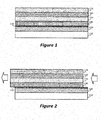
Figure 1 is a non-limiting example of coatings applied to a blade surface. -
Figure 2 is another non-limiting example of coatings applied to a blade surface and the creeping that may result. -
Figure 3 is a non-limiting example of a fiber mesh that may be applied to or embedded in a bond coat on a gas turbine blade. -
Figure 4 is another non-limiting example of a fiber mesh that may be applied to or embedded in a bond coat on a gas turbine blade. -
Figure 5 is a non-limiting example of a fiber mesh applied to a blade such that creep resistance is increased. -
Figure 6 is another non-limiting example of a fiber mesh applied to a blade such that creep resistance is increased. -
Figure 7 is a non-limiting example of a fiber mesh that may be applied to or embedded in a bond coat on a gas turbine blade. -
Figure 8 is another non-limiting example of a fiber mesh that may be applied to or embedded in a bond coat on a gas turbine blade and applied environmental barrier coating (EBC) layers. -
Figure 9 is a non-limiting example of a fiber mesh that may be applied to or embedded in a bond coat on a gas turbine blade. -
Figure 10 is another non-limiting example of a fiber mesh that may be applied to or embedded in a bond coat on a gas turbine blade and applied EBC layers. - In an embodiment, an environmental barrier coating (EBC) may be applied to gas turbine blade constructed from a ceramic matrix composite (CMC). An EBC may help protect the blade from the effects of environmental objects such as hot gas, water vapor and oxygen that may come in contact with the blade while a gas turbine is in operation. An EBC may be silicon-based, and it may be applied as several layers of various materials. In the embodiments of the present disclosure, the materials in each layer may be any material, and such materials may be applied using any means or methods, including Atmospheric Plasma Spray (APS), Chemical Vapor Deposition (CVD), Plasma enhanced CVD (PECVD), dip coating, and electro-phonetic deposition (EPD).
-
Figure 1 illustrates an example coating that may be applied to a CMC blade.Blade 110 may be coated withbond layer 120 that may serve as a bond coat and assist in bonding the EBC layers toblade 110. In an embodiment,bond layer 120 may be a silicon bond coat. EBClayer 140 may be applied onbond layer 120.Additional EBC layers layer 140. Any number of EBC layers may be applied toblade 110 and any other blade or surface disclosed herein, using any means and methods, and any material may be used for any blade, bond layer, and EBC layer disclosed herein, includingbond layer 120,EBC layers blade 110. All such embodiments are contemplated as within the scope of the present disclosure. - In the gas turbine environment in which
blade 110 may be configured, hot gasses may causebond layer 120 to oxidize and melt due to the elevated temperatures caused by such gases. Upon melting and oxidation,bond layer 120 may formviscous fluid layer 130 that may be a viscous glass layer. In some embodiments,viscous fluid layer 130 may be composed of thermally grown oxide (TGO). As shown inFigure 2 ,viscous fluid layer 130 may move under the shear stress caused by the centrifugal load applied toblade 110 and the mismatch of co-efficient thermal expansion (CTE) with the outer EBC layers, such aslayers EBC layers blade 110, especially when cracking of any oflayers - To prevent or mitigate creep, in an embodiment a bond coating may be reinforced with a porous substrate such as a fiber mesh to prevent and mitigate creep. In an embodiment using a mesh, the mesh used may be woven using fibers that intersect in two dimensions, or may be composed of unidirectional fibers. The material from which the fibers of the mesh are constructed may be any material, including ceramic fibers. In some embodiments, material for the mesh may be selected to increase the mesh's ability to fight creep. For example, the fibers of any fiber mesh disclosed herein may be made from single oxides such as Alumina, Zirconia, Titania, Magnesium oxide, Mullite, and Spinel, carbides such as Silicon carbide, Boron carbide, and Titanium carbide, nitrides such as Silicon nitride and Boron nitride, intermetallics such as Nickel aluminide, Titanium aluminide, and Molybdenum disilicide, or any combination of any of these. Because single crystal forms of oxide fibers such as alumina fibers, Mullite, and yttrium aluminum garnet (YAG) fiber have superior creep resistance above 2400F, these types of fibers may be used in some embodiments. Any of these fibers, and any other fiber that may not melt or oxidize under the operating conditions of the blade to which they are applied and that may maintain its adherent properties at high temperatures, may be used in any embodiment disclosed herein, and all such embodiments are contemplated as within the scope of the present disclosure.
-
Figure 3 illustrates a porous substrate in the form of a configuration of fibers in a fiber mesh according to one embodiment of the present disclosure. InFigure 3 , where only the fibers of a fiber mesh are shown for clarity,fibers 300 may be unidirectionally configured, where all the fibers are substantially parallel to one another. -
Figure 4 illustrates another configuration of fibers in a fiber mesh according to another embodiment of the present disclosure. InFigure 4 , where only the fibers of a fiber mesh are shown for clarity,fibers 400 may be woven together in two dimensions as seen in the figure. In either configuration, the fibers may have better oxidation and creep resistance than the EBC layers alone, and may provide a "backbone" or substrate that may hold in place the surrounding bond coat material in high temperature (e.g., 2400 F and over) applications. -
Figure 5 illustrates a side view of a gas turbine blade configured with a fiber mesh applied in or to a bond coat layer. Blade 510 may be coated withbond layer 520.Unidirectional fiber mesh 540 may be embedded, partially or entirely, inbond layer 520.EBC layer 530 may be applied overbond layer 520 andfiber mesh 540. Note that, for simplicity of explanation, a single EBC layer is shown inFigure 5 . However,EBC layer 530 may represent any number and combination of any types of EBC layers or any other layers or coatings that may be applied to a gas turbine blade. All such embodiments are contemplated as within the scope of the present disclosure. - In certain operating conditions,
viscous fluid layer 550 may form betweenbond layer 520 andEBC layer 530.Fiber mesh 540 may prevent and/or resist creep between these layers by providing a mechanical barrier or physical restraint forviscous fluid layer 550 that preventsviscous fluid layer 550 from creeping. The fibers offiber mesh 540 may serve to anchorviscous fluid layer 550 and to provide a rougher surface upon whichEBC layer 530 sits, thereby further preventing and/or reducing any movement ofEBC layer 530 due to creep. As shown inFigure 5 ,fiber mesh 540 may be applied such that the expected direction of any creep that may occur is perpendicular to the fibers infiber mesh 540. - Note that while some oxide fibers may degrade in mechanical strength at high temperature (e.g., above 2100 F) due to excessive growth of grain size, in a bond coat such as
bond layer 520, the stress may remain low enough that the fiber may retain its integrity. However, even if the fibers offiber mesh 540 break, in the embodiment ofFigure 5 and other embodiments, the broken fiber pieces may serve as "short fiber" reinforcement for a viscous fluid layer (e.g., TGO) such asviscous fluid layer 550. -
Figure 6 illustrates a side view of a gas turbine blade configured with a fiber mesh applied in or to a bond coat layer.Blade 610 may be coated withbond layer 620. Two dimensionalwoven fiber mesh 640 may be embedded, partially or entirely, inbond layer 620.EBC layer 630 may be applied overbond layer 620 andfiber mesh 640. Note that, for simplicity of explanation, a single EBC layer is shown inFigure 6 . However,EBC layer 630 may represent any number and combination of any types of EBC layers or any other layers or coatings that may be applied to a gas turbine blade. All such embodiments are contemplated as within the scope of the present disclosure. - In certain operating conditions,
viscous fluid layer 650 may form betweenbond layer 620 andEBC layer 630.Fiber mesh 640 may prevent and/or resist creep between these layers by providing a mechanical barrier or physical restraint forviscous fluid layer 650 that preventsviscous fluid layer 650 from creeping. The fibers offiber mesh 640 may serve to anchorviscous fluid layer 650 and to provide a rougher surface upon whichEBC layer 630 sits, thereby further preventing and/or reducing any movement ofEBC layer 630 due to creep. As shown inFigure 6 ,fiber mesh 640 may be applied such that the expected direction of any creep that may occur is perpendicular to the fibers oriented in one direction infiber mesh 640. Here again, even if the fibers offiber mesh 640 break, in the embodiment ofFigure 6 the broken fiber pieces may serve as "short fiber" reinforcement for a viscous fluid layer (e.g., TGO) such asviscous fluid layer 650. -
Figure 7 is a perspective view of a gas turbine blade configured with a unidirectional fiber mesh applied in or to a bond coat layer.Blade 710 may havebond layer 720 applied, andfiber mesh 740 may be embedded in or applied tobond layer 720. Note thatfiber mesh 740 may be oriented such that it is perpendicular to the expected creep direction.Figure 8 is a perspective view of the embodiment ofFigure 7 , including an expanded and partially transparent view of the layers andblade 710, withEBC layers 730 applied. -
Figure 9 is a perspective view of a gas turbine blade configured with a woven fiber mesh applied in or to a bond coat layer.Blade 910 may havebond layer 920 applied, andfiber mesh 940 may be embedded in or applied tobond layer 920. Note thatfiber mesh 940 may be oriented such at least some of the fibers offiber mesh 940 are perpendicular to the expected creep direction.Figure 10 is a perspective view of the embodiment ofFigure 9 , including an expanded and partially transparent view of the layers andblade 910, withEBC layers 930 applied. - By using the embodiment contemplated herein, a mechanical barrier may be put into place that alters the microstructure of the bond layer and EBC layers without changing the chemical composition of these layers. The mechanical barrier may be in the form of a mesh, screen, lattice or other porous substrate. In some embodiments, rather than fibers that are continuous, individual and unconnected elements of any material, such as ceramic elements, may be embedded in a bond layer to provide similar creep mitigation and prevention. The individual and unconnected elements may be oriented in a single orientation, multiple orientations, or may be distributed randomly such that the elements are randomly oriented in disposition.
- The use of the disclosed fiber meshes may prevent and/or reduce any creeping of EBC layers on a bond coat layer due to the generation of a viscous fluid layer. Thus the lifespan of blades used in gas turbines may be extended with little additional cost. Note that in some embodiments, a fiber mesh of any type may be used, including those with unidirectional fibers, fibers woven in two directions, and fibers woven in more than two directions. The fibers of any fiber mesh disclosed herein may be woven in any pattern and by any means or methods. In some embodiments, the fibers used are continuous ceramic fibers. Note also that such a fiber mesh may be applied to the entire bond-coated surface of a gas turbine blade, or alternatively applied to the sections of the gas turbine blade that are most prone to experiencing creep, such as those sections that are likely to experience the highest operating temperatures. All such embodiments are contemplated as within the scope of the present disclosure.
- This written description uses examples to disclose the subject matter contained herein, including the best mode, and also to enable any person skilled in the art to practice the invention, including making and using any devices or systems and performing any incorporated methods. The patentable scope of this disclosure is defined by the claims, and may include other examples that occur to those skilled in the art. Such other examples are intended to be within the scope of the claims if they have structural elements that do not differ from the literal language of the claims, or if they include equivalent structural elements with insubstantial differences from the literal languages of the claims.
Claims (15)
- A gas turbine blade comprising:a surface (110);a bond layer (120) applied to the surface;a porous substrate (300,400) applied to the bond layer; anda protective layer (140,150,160,170) applied to the bond layer such that the porous substrate is embedded between the bond layer and the protective layer (140).
- The gas turbine blade of claim 1, wherein the protective layer (140,150,160,170) comprises at least one environmental barrier coating.
- The gas turbine blade of claim 1, wherein the porous substrate comprises a fiber mesh (300,400).
- The gas turbine blade of claim 3, wherein at least some fibers of the fiber mesh are oriented perpendicular to an expected direction of creep.
- The gas turbine blade of claim 3, wherein the fiber mesh comprises fibers made from at least one of single oxides, carbides, nitrides, intermetallic, and a combination thereof.
- The gas turbine blade of claim 3, wherein the fiber mesh is applied to a first section of the surface and not applied to a second section of the surface.
- The gas turbine blade of any preceding claim, wherein the porous substrate comprises woven fibers.
- The gas turbine blade of any preceding claim, wherein the porous substrate comprises a mesh of continuous ceramic fibers.
- The gas turbine blade of any preceding claim, wherein the porous substrate is applied to the entirety of the surface.
- The gas turbine blade of any preceding claim, wherein the porous substrate comprises fibers made from a single crystal for of an oxide fiber.
- A method comprising:applying a bond layer (120) to a surface (110) of a gas turbine blade;applying a porous substrate (300,400) to the bond layer; andapplying a protective layer (140,150,160,170) to the bond layer such that the porous substrate is embedded between the bond layer and the protective layer.
- The method of claim 11, wherein the porous substrate comprises a fiber mesh.
- The method of claim 12, wherein applying the fiber mesh to the bond layer comprises applying the fiber mesh to the bond layer such that at least some fibers of the fiber mesh are oriented perpendicular to an expected direction of creep.
- The method of any one of claims 11 to 13, wherein applying the porous substrate to the bond layer comprised applying the porous substrate to a first section of the surface covered by the bond layer and not applying the porous substrate to a second section of the surface covered by the bond layer.
- The method of any one of claims 11 to 13, wherein applying the porous substrate to the bond layer comprised applying the porous substrate to the entirety of the surface covered by the bond layer.
Applications Claiming Priority (1)
| Application Number | Priority Date | Filing Date | Title |
|---|---|---|---|
| US13/348,212 US9771811B2 (en) | 2012-01-11 | 2012-01-11 | Continuous fiber reinforced mesh bond coat for environmental barrier coating system |
Publications (2)
| Publication Number | Publication Date |
|---|---|
| EP2615250A1 true EP2615250A1 (en) | 2013-07-17 |
| EP2615250B1 EP2615250B1 (en) | 2017-04-05 |
Family
ID=47563177
Family Applications (1)
| Application Number | Title | Priority Date | Filing Date |
|---|---|---|---|
| EP13150246.0A Active EP2615250B1 (en) | 2012-01-11 | 2013-01-04 | Continuous fiber reinforced mesh bond coat for environmental barrier coating system |
Country Status (5)
| Country | Link |
|---|---|
| US (1) | US9771811B2 (en) |
| EP (1) | EP2615250B1 (en) |
| JP (1) | JP6106431B2 (en) |
| CN (1) | CN103206265B (en) |
| RU (1) | RU2013102456A (en) |
Cited By (7)
| Publication number | Priority date | Publication date | Assignee | Title |
|---|---|---|---|---|
| WO2014092916A1 (en) * | 2012-12-11 | 2014-06-19 | General Electric Company | Environmental barrier coatings and methods therefor |
| EP3059333A1 (en) * | 2015-02-17 | 2016-08-24 | United Technologies Corporation | Toughened bond layer and method of production |
| US9561986B2 (en) | 2013-10-31 | 2017-02-07 | General Electric Company | Silica-forming articles having engineered surfaces to enhance resistance to creep sliding under high-temperature loading |
| EP3604257A1 (en) * | 2018-08-03 | 2020-02-05 | United Technologies Corporation | Fiber-reinforced self-healing bond coat |
| US10934220B2 (en) | 2018-08-16 | 2021-03-02 | Raytheon Technologies Corporation | Chemical and topological surface modification to enhance coating adhesion and compatibility |
| US11505506B2 (en) | 2018-08-16 | 2022-11-22 | Raytheon Technologies Corporation | Self-healing environmental barrier coating |
| US11535571B2 (en) | 2018-08-16 | 2022-12-27 | Raytheon Technologies Corporation | Environmental barrier coating for enhanced resistance to attack by molten silicate deposits |
Families Citing this family (20)
| Publication number | Priority date | Publication date | Assignee | Title |
|---|---|---|---|---|
| GB201118419D0 (en) * | 2011-10-25 | 2011-12-07 | Blade Dynamics Ltd | A method of making a root end joint of a wind turbine blade and a root segment for such a joint |
| WO2015069335A2 (en) * | 2013-09-09 | 2015-05-14 | United Technologies Corporation | Fan blades and manufacture methods |
| WO2015034612A1 (en) * | 2013-09-09 | 2015-03-12 | United Technologies Corporation | Fan blades and manufacture methods |
| WO2015127235A1 (en) * | 2014-02-23 | 2015-08-27 | Noble Jerry Wayne | Stucco-based surfacing system and method |
| US9713859B2 (en) | 2014-10-07 | 2017-07-25 | Siemens Energy, Inc. | Filler mesh for laser cladding |
| CN104962886B (en) * | 2015-06-08 | 2017-04-26 | 哈尔滨工程大学 | Preparation method of thermal barrier coating with bonding layer doped by chemically-plated yttria stabilized zirconia (YSZ) fiber |
| US10787391B2 (en) | 2016-09-16 | 2020-09-29 | General Electric Company | Silicon-based materials containing boron |
| US10214457B2 (en) | 2016-09-16 | 2019-02-26 | General Electric Company | Compositions containing gallium and/or indium and methods of forming the same |
| US10214456B2 (en) | 2016-09-16 | 2019-02-26 | General Electric Company | Silicon compositions containing boron and methods of forming the same |
| US10138740B2 (en) | 2016-09-16 | 2018-11-27 | General Electric Company | Silicon-based materials containing gallium and methods of forming the same |
| US9944563B2 (en) | 2016-09-16 | 2018-04-17 | General Electric Company | Silicon-based materials containing indium and methods of forming the same |
| US10259716B2 (en) | 2016-09-16 | 2019-04-16 | General Electric Company | Boron doped rare earth metal oxide compound |
| US10294112B2 (en) | 2016-09-16 | 2019-05-21 | General Electric Company | Silicon compositions containing boron and methods of forming the same |
| US20180087387A1 (en) * | 2016-09-28 | 2018-03-29 | General Electric Company | Compositions and methods for coating metal turbine blade tips |
| US11492298B2 (en) | 2018-07-31 | 2022-11-08 | General Electric Company | Silicon bond coat with columnar grains and methods of its formation |
| US10861816B2 (en) | 2018-10-18 | 2020-12-08 | Toyota Motor Engineering & Manufacturing North America, Inc. | Electronic assemblies having a mesh bond material and methods of forming thereof |
| US11643369B2 (en) * | 2019-09-13 | 2023-05-09 | Rolls-Royce Corporation | Cool side coating for ceramic or ceramic matrix composite article |
| US11624289B2 (en) * | 2021-04-21 | 2023-04-11 | Rolls-Royce Corporation | Barrier layer and surface preparation thereof |
| US12196107B2 (en) * | 2023-02-22 | 2025-01-14 | General Electric Company | Turbine engine with a blade having woven core and toughened region |
| GB202302779D0 (en) * | 2023-02-27 | 2023-04-12 | Rolls Royce Plc | Coating system and method for maintenance thereof |
Citations (4)
| Publication number | Priority date | Publication date | Assignee | Title |
|---|---|---|---|---|
| US4576874A (en) * | 1984-10-03 | 1986-03-18 | Westinghouse Electric Corp. | Spalling and corrosion resistant ceramic coating for land and marine combustion turbines |
| WO2001098232A1 (en) * | 2000-06-20 | 2001-12-27 | Honeywell International Inc. | Protective coating including porouos silicon nitride matrix and noble metal |
| EP2233450A1 (en) * | 2009-03-27 | 2010-09-29 | Alstom Technology Ltd | Multilayer thermal protection system and its use |
| WO2011137244A1 (en) * | 2010-04-30 | 2011-11-03 | Rolls-Royce Corporation | Durable environmental barrier coatings for ceramic substrates |
Family Cites Families (33)
| Publication number | Priority date | Publication date | Assignee | Title |
|---|---|---|---|---|
| US3679324A (en) * | 1970-12-04 | 1972-07-25 | United Aircraft Corp | Filament reinforced gas turbine blade |
| US3717419A (en) * | 1971-07-09 | 1973-02-20 | Susquehanna Corp | Turbine blade |
| US4503130A (en) | 1981-12-14 | 1985-03-05 | United Technologies Corporation | Prestressed ceramic coatings |
| US4764089A (en) | 1986-08-07 | 1988-08-16 | Allied-Signal Inc. | Abradable strain-tolerant ceramic coated turbine shroud |
| US4803105A (en) | 1987-02-13 | 1989-02-07 | Essex Specialty Products, Inc. | Reinforcing sheet for the reinforcement of panel and method of reinforcing panel |
| US5498484A (en) * | 1990-05-07 | 1996-03-12 | General Electric Company | Thermal barrier coating system with hardenable bond coat |
| JPH08224445A (en) | 1994-12-20 | 1996-09-03 | Hitachi Ltd | Catalyst-containing heat shield member and gas turbine using the same |
| US5952110A (en) | 1996-12-24 | 1999-09-14 | General Electric Company | Abrasive ceramic matrix turbine blade tip and method for forming |
| US6224963B1 (en) | 1997-05-14 | 2001-05-01 | Alliedsignal Inc. | Laser segmented thick thermal barrier coatings for turbine shrouds |
| US6165600A (en) | 1998-10-06 | 2000-12-26 | General Electric Company | Gas turbine engine component having a thermal-insulating multilayer ceramic coating |
| US6670046B1 (en) | 2000-08-31 | 2003-12-30 | Siemens Westinghouse Power Corporation | Thermal barrier coating system for turbine components |
| US8357454B2 (en) | 2001-08-02 | 2013-01-22 | Siemens Energy, Inc. | Segmented thermal barrier coating |
| WO2004011688A2 (en) | 2002-07-25 | 2004-02-05 | University Of Virginia Patent Foundation | Method and apparatus for dispersion strengthened bond coats for thermal barrier coatings |
| US6699607B1 (en) | 2002-10-30 | 2004-03-02 | General Electric Company | Thermal/environmental barrier coating for silicon-containing substrates |
| US7056574B2 (en) | 2003-05-22 | 2006-06-06 | United Technologies Corporation | Bond layer for silicon containing substrate |
| US6984277B2 (en) | 2003-07-31 | 2006-01-10 | Siemens Westinghouse Power Corporation | Bond enhancement for thermally insulated ceramic matrix composite materials |
| US6979498B2 (en) | 2003-11-25 | 2005-12-27 | General Electric Company | Strengthened bond coats for thermal barrier coatings |
| US7090894B2 (en) | 2004-02-10 | 2006-08-15 | General Electric Company | Bondcoat for the application of TBC's and wear coatings to oxide ceramic matrix |
| TWM260059U (en) | 2004-07-08 | 2005-03-21 | Blueexpert Technology Corp | Computer input device having bluetooth handsfree handset |
| EP1645653A1 (en) | 2004-10-07 | 2006-04-12 | Siemens Aktiengesellschaft | Coating system |
| US7374825B2 (en) | 2004-12-01 | 2008-05-20 | General Electric Company | Protection of thermal barrier coating by an impermeable barrier coating |
| EP1734145A1 (en) | 2005-06-13 | 2006-12-20 | Siemens Aktiengesellschaft | Coating system for a component having a thermal barrier coating and an erosion resistant coating, method for manufacturing and method for using said component |
| JP2007071185A (en) | 2005-09-09 | 2007-03-22 | Chugoku Electric Power Co Inc:The | Shroud for gas turbine |
| JP4731271B2 (en) | 2005-10-12 | 2011-07-20 | 新日本製鐵株式会社 | Fiber reinforced refractory |
| WO2007098152A2 (en) | 2006-02-20 | 2007-08-30 | Lee Kang N | Article including enviromental barrier coating system |
| JP4959213B2 (en) | 2006-03-31 | 2012-06-20 | 三菱重工業株式会社 | Thermal barrier coating member and manufacturing method thereof, thermal barrier coating material, gas turbine, and sintered body |
| US7740948B1 (en) | 2006-05-31 | 2010-06-22 | The United States Of America As Represented By The United States Department Of Energy | Thermal barrier coatings |
| US20080044663A1 (en) | 2006-08-18 | 2008-02-21 | United Technologies Corporation | Dual layer ceramic coating |
| US8241003B2 (en) * | 2008-01-23 | 2012-08-14 | United Technologies Corp. | Systems and methods involving localized stiffening of blades |
| US8123463B2 (en) * | 2008-07-31 | 2012-02-28 | General Electric Company | Method and system for manufacturing a blade |
| US7927714B2 (en) | 2008-08-20 | 2011-04-19 | The Trustees Of Princeton University | Barium-doped bond coat for thermal barrier coatings |
| US8470460B2 (en) * | 2008-11-25 | 2013-06-25 | Rolls-Royce Corporation | Multilayer thermal barrier coatings |
| US20100129673A1 (en) * | 2008-11-25 | 2010-05-27 | Rolls-Royce Corporation | Reinforced oxide coatings |
-
2012
- 2012-01-11 US US13/348,212 patent/US9771811B2/en active Active
- 2012-12-28 JP JP2012286488A patent/JP6106431B2/en not_active Expired - Fee Related
-
2013
- 2013-01-04 EP EP13150246.0A patent/EP2615250B1/en active Active
- 2013-01-09 RU RU2013102456/06A patent/RU2013102456A/en not_active Application Discontinuation
- 2013-01-11 CN CN201310011114.1A patent/CN103206265B/en active Active
Patent Citations (4)
| Publication number | Priority date | Publication date | Assignee | Title |
|---|---|---|---|---|
| US4576874A (en) * | 1984-10-03 | 1986-03-18 | Westinghouse Electric Corp. | Spalling and corrosion resistant ceramic coating for land and marine combustion turbines |
| WO2001098232A1 (en) * | 2000-06-20 | 2001-12-27 | Honeywell International Inc. | Protective coating including porouos silicon nitride matrix and noble metal |
| EP2233450A1 (en) * | 2009-03-27 | 2010-09-29 | Alstom Technology Ltd | Multilayer thermal protection system and its use |
| WO2011137244A1 (en) * | 2010-04-30 | 2011-11-03 | Rolls-Royce Corporation | Durable environmental barrier coatings for ceramic substrates |
Cited By (13)
| Publication number | Priority date | Publication date | Assignee | Title |
|---|---|---|---|---|
| EP3865603A1 (en) * | 2012-12-11 | 2021-08-18 | General Electric Company | Environmental barrier coatings and methods therefor |
| JP2016506315A (en) * | 2012-12-11 | 2016-03-03 | ゼネラル・エレクトリック・カンパニイ | Environmental barrier coating and method thereof |
| US9428650B2 (en) | 2012-12-11 | 2016-08-30 | General Electric Company | Environmental barrier coatings and methods therefor |
| WO2014092916A1 (en) * | 2012-12-11 | 2014-06-19 | General Electric Company | Environmental barrier coatings and methods therefor |
| US9561986B2 (en) | 2013-10-31 | 2017-02-07 | General Electric Company | Silica-forming articles having engineered surfaces to enhance resistance to creep sliding under high-temperature loading |
| EP3059333A1 (en) * | 2015-02-17 | 2016-08-24 | United Technologies Corporation | Toughened bond layer and method of production |
| US10414694B2 (en) | 2015-02-17 | 2019-09-17 | United Technologies Corporation | Toughened bond layer and method of production |
| EP3604257A1 (en) * | 2018-08-03 | 2020-02-05 | United Technologies Corporation | Fiber-reinforced self-healing bond coat |
| US11668198B2 (en) | 2018-08-03 | 2023-06-06 | Raytheon Technologies Corporation | Fiber-reinforced self-healing environmental barrier coating |
| US10934220B2 (en) | 2018-08-16 | 2021-03-02 | Raytheon Technologies Corporation | Chemical and topological surface modification to enhance coating adhesion and compatibility |
| US11505506B2 (en) | 2018-08-16 | 2022-11-22 | Raytheon Technologies Corporation | Self-healing environmental barrier coating |
| US11535571B2 (en) | 2018-08-16 | 2022-12-27 | Raytheon Technologies Corporation | Environmental barrier coating for enhanced resistance to attack by molten silicate deposits |
| US11905222B2 (en) | 2018-08-16 | 2024-02-20 | Rtx Corporation | Environmental barrier coating for enhanced resistance to attack by molten silicate deposits |
Also Published As
| Publication number | Publication date |
|---|---|
| CN103206265A (en) | 2013-07-17 |
| US20130177440A1 (en) | 2013-07-11 |
| RU2013102456A (en) | 2014-07-20 |
| EP2615250B1 (en) | 2017-04-05 |
| CN103206265B (en) | 2016-02-17 |
| US9771811B2 (en) | 2017-09-26 |
| JP2013142398A (en) | 2013-07-22 |
| JP6106431B2 (en) | 2017-03-29 |
Similar Documents
| Publication | Publication Date | Title |
|---|---|---|
| EP2615250B1 (en) | Continuous fiber reinforced mesh bond coat for environmental barrier coating system | |
| EP2508648B1 (en) | Component for a turbomachine and method for manufacturing such a component | |
| JP6412024B2 (en) | High temperature resistant ceramic matrix composite and environmental protection coating | |
| US7540710B2 (en) | Turbine blade for use in a gas turbine | |
| US20130136915A1 (en) | Durable environmental barrier coatings for ceramic substrates | |
| CN108727066B (en) | Segmented environmental barrier coating system and method of forming the same | |
| EP2674576A1 (en) | Reinforced Coatings and Methods of Making the Same | |
| EP2189504A1 (en) | Reinforced oxide coatings | |
| US11473432B2 (en) | Anti-CMAS coating with enhanced efficiency | |
| US10294802B2 (en) | Turbine engine components with chemical vapor infiltrated isolation layers | |
| EP3058183B1 (en) | Segmented ceramic coating interlayer | |
| US20140255680A1 (en) | Environmental barrier coating-based thermal barrier coatings for ceramic matrix composites | |
| BR102016025139A2 (en) | engine component and method for repairing a coating | |
| JP2007247055A (en) | Coating method and coating article | |
| EP3604257B1 (en) | Article comprising a fiber-reinforced self-healing bond coat | |
| US20140011038A1 (en) | Coating system for a gas turbine component | |
| EP3800043B1 (en) | Silicon oxycarbide-based environmental barrier coating | |
| EP2698446A2 (en) | Crack-resistant environmental barrier coatings | |
| EP2615247A2 (en) | Creep resistant coating for ceramic turbine blades | |
| RU2568205C2 (en) | Thermoerosional coating for carbon-carbonic composite materials | |
| WO2007025842A1 (en) | The invention relates to a turbine or vane, in particular for use in a combustion turbine | |
| US20140037971A1 (en) | Reinforced articles and methods of making the same | |
| BR112019026201B1 (en) | COATED GAS TURBINE ENGINE PART, AND, PROCESS FOR MANUFACTURING A PART |
Legal Events
| Date | Code | Title | Description |
|---|---|---|---|
| PUAI | Public reference made under article 153(3) epc to a published international application that has entered the european phase |
Free format text: ORIGINAL CODE: 0009012 |
|
| AK | Designated contracting states |
Kind code of ref document: A1 Designated state(s): AL AT BE BG CH CY CZ DE DK EE ES FI FR GB GR HR HU IE IS IT LI LT LU LV MC MK MT NL NO PL PT RO RS SE SI SK SM TR |
|
| AX | Request for extension of the european patent |
Extension state: BA ME |
|
| 17P | Request for examination filed |
Effective date: 20140117 |
|
| RBV | Designated contracting states (corrected) |
Designated state(s): AL AT BE BG CH CY CZ DE DK EE ES FI FR GB GR HR HU IE IS IT LI LT LU LV MC MK MT NL NO PL PT RO RS SE SI SK SM TR |
|
| GRAP | Despatch of communication of intention to grant a patent |
Free format text: ORIGINAL CODE: EPIDOSNIGR1 |
|
| RIC1 | Information provided on ipc code assigned before grant |
Ipc: C04B 41/52 20060101ALI20161116BHEP Ipc: C04B 41/89 20060101ALI20161116BHEP Ipc: F01D 5/28 20060101AFI20161116BHEP Ipc: C04B 41/00 20060101ALI20161116BHEP |
|
| INTG | Intention to grant announced |
Effective date: 20161216 |
|
| GRAS | Grant fee paid |
Free format text: ORIGINAL CODE: EPIDOSNIGR3 |
|
| GRAA | (expected) grant |
Free format text: ORIGINAL CODE: 0009210 |
|
| AK | Designated contracting states |
Kind code of ref document: B1 Designated state(s): AL AT BE BG CH CY CZ DE DK EE ES FI FR GB GR HR HU IE IS IT LI LT LU LV MC MK MT NL NO PL PT RO RS SE SI SK SM TR |
|
| REG | Reference to a national code |
Ref country code: GB Ref legal event code: FG4D |
|
| REG | Reference to a national code |
Ref country code: CH Ref legal event code: EP |
|
| REG | Reference to a national code |
Ref country code: AT Ref legal event code: REF Ref document number: 882030 Country of ref document: AT Kind code of ref document: T Effective date: 20170415 |
|
| REG | Reference to a national code |
Ref country code: IE Ref legal event code: FG4D |
|
| REG | Reference to a national code |
Ref country code: DE Ref legal event code: R096 Ref document number: 602013019320 Country of ref document: DE |
|
| REG | Reference to a national code |
Ref country code: NL Ref legal event code: MP Effective date: 20170405 |
|
| REG | Reference to a national code |
Ref country code: LT Ref legal event code: MG4D |
|
| REG | Reference to a national code |
Ref country code: AT Ref legal event code: MK05 Ref document number: 882030 Country of ref document: AT Kind code of ref document: T Effective date: 20170405 |
|
| PG25 | Lapsed in a contracting state [announced via postgrant information from national office to epo] |
Ref country code: NL Free format text: LAPSE BECAUSE OF FAILURE TO SUBMIT A TRANSLATION OF THE DESCRIPTION OR TO PAY THE FEE WITHIN THE PRESCRIBED TIME-LIMIT Effective date: 20170405 |
|
| PG25 | Lapsed in a contracting state [announced via postgrant information from national office to epo] |
Ref country code: HR Free format text: LAPSE BECAUSE OF FAILURE TO SUBMIT A TRANSLATION OF THE DESCRIPTION OR TO PAY THE FEE WITHIN THE PRESCRIBED TIME-LIMIT Effective date: 20170405 Ref country code: NO Free format text: LAPSE BECAUSE OF FAILURE TO SUBMIT A TRANSLATION OF THE DESCRIPTION OR TO PAY THE FEE WITHIN THE PRESCRIBED TIME-LIMIT Effective date: 20170705 Ref country code: LT Free format text: LAPSE BECAUSE OF FAILURE TO SUBMIT A TRANSLATION OF THE DESCRIPTION OR TO PAY THE FEE WITHIN THE PRESCRIBED TIME-LIMIT Effective date: 20170405 Ref country code: ES Free format text: LAPSE BECAUSE OF FAILURE TO SUBMIT A TRANSLATION OF THE DESCRIPTION OR TO PAY THE FEE WITHIN THE PRESCRIBED TIME-LIMIT Effective date: 20170405 Ref country code: FI Free format text: LAPSE BECAUSE OF FAILURE TO SUBMIT A TRANSLATION OF THE DESCRIPTION OR TO PAY THE FEE WITHIN THE PRESCRIBED TIME-LIMIT Effective date: 20170405 Ref country code: GR Free format text: LAPSE BECAUSE OF FAILURE TO SUBMIT A TRANSLATION OF THE DESCRIPTION OR TO PAY THE FEE WITHIN THE PRESCRIBED TIME-LIMIT Effective date: 20170706 Ref country code: AT Free format text: LAPSE BECAUSE OF FAILURE TO SUBMIT A TRANSLATION OF THE DESCRIPTION OR TO PAY THE FEE WITHIN THE PRESCRIBED TIME-LIMIT Effective date: 20170405 |
|
| PG25 | Lapsed in a contracting state [announced via postgrant information from national office to epo] |
Ref country code: LV Free format text: LAPSE BECAUSE OF FAILURE TO SUBMIT A TRANSLATION OF THE DESCRIPTION OR TO PAY THE FEE WITHIN THE PRESCRIBED TIME-LIMIT Effective date: 20170405 Ref country code: SE Free format text: LAPSE BECAUSE OF FAILURE TO SUBMIT A TRANSLATION OF THE DESCRIPTION OR TO PAY THE FEE WITHIN THE PRESCRIBED TIME-LIMIT Effective date: 20170405 Ref country code: RS Free format text: LAPSE BECAUSE OF FAILURE TO SUBMIT A TRANSLATION OF THE DESCRIPTION OR TO PAY THE FEE WITHIN THE PRESCRIBED TIME-LIMIT Effective date: 20170405 Ref country code: BG Free format text: LAPSE BECAUSE OF FAILURE TO SUBMIT A TRANSLATION OF THE DESCRIPTION OR TO PAY THE FEE WITHIN THE PRESCRIBED TIME-LIMIT Effective date: 20170705 Ref country code: PL Free format text: LAPSE BECAUSE OF FAILURE TO SUBMIT A TRANSLATION OF THE DESCRIPTION OR TO PAY THE FEE WITHIN THE PRESCRIBED TIME-LIMIT Effective date: 20170405 Ref country code: IS Free format text: LAPSE BECAUSE OF FAILURE TO SUBMIT A TRANSLATION OF THE DESCRIPTION OR TO PAY THE FEE WITHIN THE PRESCRIBED TIME-LIMIT Effective date: 20170805 |
|
| REG | Reference to a national code |
Ref country code: DE Ref legal event code: R097 Ref document number: 602013019320 Country of ref document: DE |
|
| REG | Reference to a national code |
Ref country code: FR Ref legal event code: PLFP Year of fee payment: 6 |
|
| PG25 | Lapsed in a contracting state [announced via postgrant information from national office to epo] |
Ref country code: DK Free format text: LAPSE BECAUSE OF FAILURE TO SUBMIT A TRANSLATION OF THE DESCRIPTION OR TO PAY THE FEE WITHIN THE PRESCRIBED TIME-LIMIT Effective date: 20170405 Ref country code: RO Free format text: LAPSE BECAUSE OF FAILURE TO SUBMIT A TRANSLATION OF THE DESCRIPTION OR TO PAY THE FEE WITHIN THE PRESCRIBED TIME-LIMIT Effective date: 20170405 Ref country code: EE Free format text: LAPSE BECAUSE OF FAILURE TO SUBMIT A TRANSLATION OF THE DESCRIPTION OR TO PAY THE FEE WITHIN THE PRESCRIBED TIME-LIMIT Effective date: 20170405 Ref country code: CZ Free format text: LAPSE BECAUSE OF FAILURE TO SUBMIT A TRANSLATION OF THE DESCRIPTION OR TO PAY THE FEE WITHIN THE PRESCRIBED TIME-LIMIT Effective date: 20170405 Ref country code: SK Free format text: LAPSE BECAUSE OF FAILURE TO SUBMIT A TRANSLATION OF THE DESCRIPTION OR TO PAY THE FEE WITHIN THE PRESCRIBED TIME-LIMIT Effective date: 20170405 |
|
| PLBE | No opposition filed within time limit |
Free format text: ORIGINAL CODE: 0009261 |
|
| STAA | Information on the status of an ep patent application or granted ep patent |
Free format text: STATUS: NO OPPOSITION FILED WITHIN TIME LIMIT |
|
| PG25 | Lapsed in a contracting state [announced via postgrant information from national office to epo] |
Ref country code: SM Free format text: LAPSE BECAUSE OF FAILURE TO SUBMIT A TRANSLATION OF THE DESCRIPTION OR TO PAY THE FEE WITHIN THE PRESCRIBED TIME-LIMIT Effective date: 20170405 |
|
| 26N | No opposition filed |
Effective date: 20180108 |
|
| PG25 | Lapsed in a contracting state [announced via postgrant information from national office to epo] |
Ref country code: SI Free format text: LAPSE BECAUSE OF FAILURE TO SUBMIT A TRANSLATION OF THE DESCRIPTION OR TO PAY THE FEE WITHIN THE PRESCRIBED TIME-LIMIT Effective date: 20170405 |
|
| REG | Reference to a national code |
Ref country code: CH Ref legal event code: PL |
|
| PG25 | Lapsed in a contracting state [announced via postgrant information from national office to epo] |
Ref country code: LU Free format text: LAPSE BECAUSE OF NON-PAYMENT OF DUE FEES Effective date: 20180104 |
|
| REG | Reference to a national code |
Ref country code: IE Ref legal event code: MM4A |
|
| REG | Reference to a national code |
Ref country code: BE Ref legal event code: MM Effective date: 20180131 |
|
| PG25 | Lapsed in a contracting state [announced via postgrant information from national office to epo] |
Ref country code: CH Free format text: LAPSE BECAUSE OF NON-PAYMENT OF DUE FEES Effective date: 20180131 Ref country code: BE Free format text: LAPSE BECAUSE OF NON-PAYMENT OF DUE FEES Effective date: 20180131 Ref country code: LI Free format text: LAPSE BECAUSE OF NON-PAYMENT OF DUE FEES Effective date: 20180131 |
|
| PG25 | Lapsed in a contracting state [announced via postgrant information from national office to epo] |
Ref country code: IE Free format text: LAPSE BECAUSE OF NON-PAYMENT OF DUE FEES Effective date: 20180104 |
|
| PG25 | Lapsed in a contracting state [announced via postgrant information from national office to epo] |
Ref country code: MC Free format text: LAPSE BECAUSE OF FAILURE TO SUBMIT A TRANSLATION OF THE DESCRIPTION OR TO PAY THE FEE WITHIN THE PRESCRIBED TIME-LIMIT Effective date: 20170405 |
|
| PG25 | Lapsed in a contracting state [announced via postgrant information from national office to epo] |
Ref country code: MT Free format text: LAPSE BECAUSE OF NON-PAYMENT OF DUE FEES Effective date: 20180104 |
|
| PG25 | Lapsed in a contracting state [announced via postgrant information from national office to epo] |
Ref country code: TR Free format text: LAPSE BECAUSE OF FAILURE TO SUBMIT A TRANSLATION OF THE DESCRIPTION OR TO PAY THE FEE WITHIN THE PRESCRIBED TIME-LIMIT Effective date: 20170405 |
|
| PGFP | Annual fee paid to national office [announced via postgrant information from national office to epo] |
Ref country code: GB Payment date: 20191223 Year of fee payment: 8 |
|
| PG25 | Lapsed in a contracting state [announced via postgrant information from national office to epo] |
Ref country code: HU Free format text: LAPSE BECAUSE OF FAILURE TO SUBMIT A TRANSLATION OF THE DESCRIPTION OR TO PAY THE FEE WITHIN THE PRESCRIBED TIME-LIMIT; INVALID AB INITIO Effective date: 20130104 Ref country code: PT Free format text: LAPSE BECAUSE OF FAILURE TO SUBMIT A TRANSLATION OF THE DESCRIPTION OR TO PAY THE FEE WITHIN THE PRESCRIBED TIME-LIMIT Effective date: 20170405 |
|
| PG25 | Lapsed in a contracting state [announced via postgrant information from national office to epo] |
Ref country code: CY Free format text: LAPSE BECAUSE OF FAILURE TO SUBMIT A TRANSLATION OF THE DESCRIPTION OR TO PAY THE FEE WITHIN THE PRESCRIBED TIME-LIMIT Effective date: 20170405 Ref country code: MK Free format text: LAPSE BECAUSE OF NON-PAYMENT OF DUE FEES Effective date: 20170405 |
|
| PG25 | Lapsed in a contracting state [announced via postgrant information from national office to epo] |
Ref country code: AL Free format text: LAPSE BECAUSE OF FAILURE TO SUBMIT A TRANSLATION OF THE DESCRIPTION OR TO PAY THE FEE WITHIN THE PRESCRIBED TIME-LIMIT Effective date: 20170405 |
|
| GBPC | Gb: european patent ceased through non-payment of renewal fee |
Effective date: 20210104 |
|
| PG25 | Lapsed in a contracting state [announced via postgrant information from national office to epo] |
Ref country code: GB Free format text: LAPSE BECAUSE OF NON-PAYMENT OF DUE FEES Effective date: 20210104 |
|
| PGFP | Annual fee paid to national office [announced via postgrant information from national office to epo] |
Ref country code: DE Payment date: 20211215 Year of fee payment: 10 |
|
| PGFP | Annual fee paid to national office [announced via postgrant information from national office to epo] |
Ref country code: IT Payment date: 20220103 Year of fee payment: 10 |
|
| REG | Reference to a national code |
Ref country code: DE Ref legal event code: R119 Ref document number: 602013019320 Country of ref document: DE |
|
| PG25 | Lapsed in a contracting state [announced via postgrant information from national office to epo] |
Ref country code: DE Free format text: LAPSE BECAUSE OF NON-PAYMENT OF DUE FEES Effective date: 20230801 |
|
| PG25 | Lapsed in a contracting state [announced via postgrant information from national office to epo] |
Ref country code: IT Free format text: LAPSE BECAUSE OF NON-PAYMENT OF DUE FEES Effective date: 20230104 |
|
| PGFP | Annual fee paid to national office [announced via postgrant information from national office to epo] |
Ref country code: FR Payment date: 20241219 Year of fee payment: 13 |