EP2615215A1 - Faucet device - Google Patents
Faucet device Download PDFInfo
- Publication number
- EP2615215A1 EP2615215A1 EP11823300.6A EP11823300A EP2615215A1 EP 2615215 A1 EP2615215 A1 EP 2615215A1 EP 11823300 A EP11823300 A EP 11823300A EP 2615215 A1 EP2615215 A1 EP 2615215A1
- Authority
- EP
- European Patent Office
- Prior art keywords
- generator
- water
- solenoid valve
- spout port
- passage forming
- Prior art date
- Legal status (The legal status is an assumption and is not a legal conclusion. Google has not performed a legal analysis and makes no representation as to the accuracy of the status listed.)
- Withdrawn
Links
Images







Classifications
-
- H—ELECTRICITY
- H02—GENERATION; CONVERSION OR DISTRIBUTION OF ELECTRIC POWER
- H02K—DYNAMO-ELECTRIC MACHINES
- H02K7/00—Arrangements for handling mechanical energy structurally associated with dynamo-electric machines, e.g. structural association with mechanical driving motors or auxiliary dynamo-electric machines
- H02K7/18—Structural association of electric generators with mechanical driving motors, e.g. with turbines
- H02K7/1807—Rotary generators
- H02K7/1823—Rotary generators structurally associated with turbines or similar engines
-
- E—FIXED CONSTRUCTIONS
- E03—WATER SUPPLY; SEWERAGE
- E03C—DOMESTIC PLUMBING INSTALLATIONS FOR FRESH WATER OR WASTE WATER; SINKS
- E03C1/00—Domestic plumbing installations for fresh water or waste water; Sinks
- E03C1/02—Plumbing installations for fresh water
- E03C1/04—Water-basin installations specially adapted to wash-basins or baths
-
- E—FIXED CONSTRUCTIONS
- E03—WATER SUPPLY; SEWERAGE
- E03C—DOMESTIC PLUMBING INSTALLATIONS FOR FRESH WATER OR WASTE WATER; SINKS
- E03C1/00—Domestic plumbing installations for fresh water or waste water; Sinks
- E03C1/02—Plumbing installations for fresh water
- E03C1/05—Arrangements of devices on wash-basins, baths, sinks, or the like for remote control of taps
- E03C1/055—Electrical control devices, e.g. with push buttons, control panels or the like
-
- H—ELECTRICITY
- H02—GENERATION; CONVERSION OR DISTRIBUTION OF ELECTRIC POWER
- H02K—DYNAMO-ELECTRIC MACHINES
- H02K5/00—Casings; Enclosures; Supports
- H02K5/24—Casings; Enclosures; Supports specially adapted for suppression or reduction of noise or vibrations
Definitions
- the present invention relates to a faucet device, and in particular to a faucet device configured to drive a solenoid valve by electrical power from a built-in generator to switch between water stopping and water spouting.
- Patent Document 1 JP2008-248474A (Patent Document 1) describes an automatic faucet.
- This automatic faucet comprises a built-in generator in a device body, and is adapted to generate electrical power by the flow of water to be spouted from the faucet device.
- the electrical power generated by the generator is used for driving a solenoid valve adapted to switch between water stopping and water spouting of the faucet device.
- an automatic faucet configured to sense a user's finger with a sensor and, based on which, to open and close the solenoid valve to switch between water stopping and water spouting, without using an external power source.
- the automatic faucet which does not require any external power source provides significant advantage that it can be installed without choosing power source environment for the installation location because it operates by simply substituting for an existing faucet device that is installed in a washroom etc.
- Patent Document 1 JP2008-248474A
- the magnetic flux density of the power generating magnet or the like is increased, the electromagnetic force acting within the generator becomes greater, which becomes a source of generation of vibration.
- the electromagnetic force acting within the generator becomes greater, which becomes a source of generation of vibration.
- increasing the magnetic flux density of the power generating magnet enhances the electromagnetic force acting between the power generating magnet and the power generating coil (or a pole piece for inducing magnetism). Since this electromagnetic force varies in magnitude in association with a rotation angle of the impeller, the varying electromagnetic force creates vibration in the generator.
- the downsized generator results in a downsized and light-weighted built-in impeller, and thus the impeller becomes more likely to be vibrated.
- the automatic faucet described in JP2008-248474A has a problem that the built-in generator is directly fixed to the main body by screws (numerals 22 and 24 in FIG. 1(b) of JP2008-248474A ), so the vibration of the generator is propagated to the main body, which in turn causes an installation wall of the automatic faucet to is vibrated and is likely to generate abnormal noise.
- the vibration of the generator is propagated to the main body, which in turn causes an installation wall of the automatic faucet to is vibrated and is likely to generate abnormal noise.
- large abnormal noise is likely to be generated because larger excitation force is generated from the generator.
- the present invention is directed towards providing a faucet device which has a built-in downsized generator and is capable of suppressing abnormal noise that is generated.
- the present invention provides a faucet device configured to drive a solenoid valve by electrical power from a built-in generator to switch between water stopping and water spouting, comprising: a device body; a solenoid valve disposed within the device body, and adapted to switch between water stopping and water spouting; a spout port forming portion formed with a spout port, and adapted to cause water that passes through the solenoid valve to be spouted; an impeller-driven generator equipped with an impeller, a power generating magnet and a power generating coil, and adapted to rotate the impeller by flow of water that passes through the solenoid valve to generate electrical power for driving the solenoid valve; a solenoid valve-side water-passage forming member for guiding water that passes through the solenoid valve to the generator; a spout port-side water-passage forming member for guiding water that passes through the generator toward the spout port; a first elastic member
- the water that has passed through the solenoid valve passes through the solenoid valve-side water-passage forming member and flows into the generator.
- the generator rotates the impeller by the flow of water that has passed through the solenoid valve to generate electrical power for driving the solenoid valve.
- the water that has flowed out from the generator is guided by the spout port-side water-passage forming member to the spout port, from which it is spouted.
- the solenoid valve side of the generator is connected to the solenoid valve-side water-passage forming member via the first elastic member, and the solenoid valve-side water-passage forming member is coupled to the device body via the third elastic member.
- the spout port side of the generator is connected to the spout port-side water-passage forming member via the second elastic member, and the spout port-side water-passage forming member is coupled to the device body via the fourth elastic member.
- the solenoid valve side of the generator is coupled to the device body via the first elastic member and the third elastic member while the spout port side of the generator is coupled to the device body via the second elastic member and the fourth elastic member, and thus the vibration propagated to the device body can be sufficiently suppressed to suppress abnormal noise that is generated.
- the invention disclosed in JP2008-248474A also includes a seal material such as an O-ring disposed between the generator and a line coupled thereto, this seal material cannot ensure a sufficient vibration stroke of the generator, so that the vibration that is propagated cannot be suppressed sufficiently.
- the propagation of the vibration is suppressed in two stages: one by the first and second elastic members disposed between the generator and the member connected thereto, and one by the third and fourth elastic members disposed between the connected member and the device body.
- This allows the first and second elastic members for ensuring water-tightness to be utilized for suppression of vibration, while sufficiently suppressing the propagation of vibration.
- ensuring of the vibration stroke is performed in two stages, so that decrease in water-tightness and degradation of stability of the elastic members can be avoided.
- the third elastic member and the fourth elastic member are configured to excite vibration having vertical components by a horizontal excitation force.
- the third and fourth elastic members excite vibration having vertical components by a horizontal excitation force, and thus the vibration of the generator would be larger in a vertical direction and smaller in a horizontal vibration.
- the vibration is mainly of the same vertical direction as the direction in which the spouted water flows, and is less recognizable by a user relative to the case in which it is vibrated in a horizontal direction. This makes it possible to sufficiently suppress the propagation of vibration of the generator, while reducing disturbance in the stream of water which is recognizable by the user to allow the faucet device to have an improved quality level.
- an impeller rotary shaft of the impeller is disposed in a substantially horizontal direction
- the third elastic member and the fourth elastic member are disposed such that a straight line connecting the third elastic member and the fourth elastic member is oriented toward a substantially horizontal direction.
- the straight line connecting the third elastic member and the fourth elastic member is oriented toward a substantially horizontal direction, and thus vertical vibrational components of the generator can be further increased and disturbance in the stream of water which is recognizable by the user can be reduced more.
- the first elastic member, the second elastic member, the third elastic member and the fourth elastic member support the generator such that the vibration of the generator on the side closer to the solenoid valve is larger than the vibration of the generator on the side closer to the spout port.
- the vibration of the generator becomes larger in a direction from the side closer to the spout port toward the side closer to the solenoid valve, and thus disturbance in the streams of spouted water can be reduced.
- vibration of the device body can be better suppressed because vibration is reduced on the spout port side which is closer to a distal end of the device body and is difficult to ensure the rigidity.
- the impeller is disposed between the third elastic member and the fourth elastic member at a position closer to the third elastic member.
- the impeller is disposed at a position closer to the third elastic member, and thus the impeller, which would be a source of vibration due to the action of electromagnetic force at the time of electrical power generation, does not strongly excite the distal end of the device body, so that vibration of the device body can be better suppressed.
- the impeller, the power generating magnet and the power generating coil are arranged along the impeller rotary shaft of the impeller.
- the moment of inertia of the rotating portion of the generator can be decreased as compared, for example, to the conventional generators in which a power generating magnet is disposed on the radially outer side of a blade of the impeller. This makes it possible to improve the power generation efficiency of the generator, decrease the magnetic flux density of the power generating magnet which is necessary to achieve power requirements, and suppress the generation of vibration.
- the impeller, the power generating coil, the power generating magnet and the impeller are disposed in this order from the side closer to the spout port.
- the impeller which would be a source of vibration is disposed at a position distant from the spout port, and thus it does not strongly excite the distal end of the device body, so that vibration of the device body can be better suppressed.
- the generator further comprises a pole piece for guiding magnetism of the power generating magnet to the power generating coil, the pole piece extending from the power generating coil to the periphery of the power generating magnet.
- magnetism of the power generating magnet is guided by the pole piece to the power generating coil, and thus the degree of freedom in placement of the power generating magnet and the power generating coil can be increased, which enables a source of vibration to be provided at a position further distant from the spout port.
- the device body is made from metal and comprises a base portion, a horizontal portion, and a cover portion, and wherein the base portion is fixed to an installation wall, the horizontal portion is integrally formed with the base portion and extending in a substantially horizontal direction from the base portion, the horizontal portion has an opening on the upper side thereof, and the cover portion detachably attached to the horizontal portion in a manner to cover the opening of the horizontal portion, and wherein the generator, the solenoid valve-side water-passage forming member and the spout port-side water-passage forming member are disposed within the horizontal portion, the third elastic member detachably couples the solenoid valve-side water-passage forming member to the horizontal portion through the opening of the horizontal portion, and the fourth elastic member detachably couples the spout port-side water-passage forming member to the horizontal portion through the opening of the horizontal portion.
- the device body comprises a base portion fixed to an installation wall, and a horizontal portion extending in a substantially horizontal direction from the base portion, wherein the device body is made from metal and is integrally formed.
- the horizontal portion is formed with an opening on the upper side thereof, which is covered by a detachably attached cover portion.
- the third elastic member and the fourth elastic member are detachably coupled to the horizontal portion through the opening.
- the base portion and the horizontal portion of the device body are made from metal and are integrally formed, and thus they are highly rigid and less likely to be vibrated by the vibration of the generator, so that the generation of abnormal noise can be suppressed.
- the horizontal portion is formed with an opening on the upper side thereof, through which a unitization of assembled generator, spout port-side water-passage forming member, solenoid valve-side water-passage forming member, and first to fourth elastic members can be inserted and mounted, enabling an easy assembly.
- Such a structure of the device body satisfies both of suppression of abnormal noise and improvement in assembly.
- the first elastic member, the second elastic member, the third elastic member and the fourth elastic member support the generator such that the vibration of the generator on the side closer to the solenoid valve is larger than the vibration of the generator on the side closer to the spout port.
- the vibration of the generator becomes larger in a direction from the side closer to the spout port toward the side closer to the solenoid valve, and thus disturbance in the streams of spouted water can be reduced.
- vibration of the device body can be better suppressed because vibration is reduced on the spout port side which is closer to a distal end of the device body and is difficult to ensure the rigidity.
- the impeller is disposed between the third elastic member and the fourth elastic member at a position closer to the third elastic member.
- the impeller is disposed at a position closer to the third elastic member, and thus the impeller, which would be a source of vibration due to the action of electromagnetic force at the time of electrical power generation, does not strongly excite the distal end of the device body, so that vibration of the device body can be better suppressed.
- the faucet device further comprises a topside elastic mount member which is disposed between the installation wall and the base portion, and wherein the topside elastic mount member is adapted to suppress vibration propagated from the device body to the installation wall.
- the topside elastic mount member is disposed between the installation wall and the base portion, and thus the vibration that is propagated from the generator to the device body can be prevented from being propagated to the installation wall, thereby the abnormal noise that is generated from the installation wall can be suppressed.
- the faucet device further comprises a fastener member and a backside elastic mount member, and wherein the fastener member is disposed on the reverse side of the installation wall, and is adapted to fix the device body to the installation wall by sandwiching the installation wall between the fastener member and the base portion, and wherein the backside elastic mount member is disposed between the fastener member and the reverse side of the installation wall, and is adapted to suppress vibration propagated to the installation wall.
- the backside elastic mount member is disposed between the fastener member and the reverse side of the installation wall, and thus the vibration propagated from the device body to the installation wall via the fastener member can be suppressed, thereby the abnormal noise that is generated from the installation wall can be further suppressed.
- a downsized built-in generator can be included, while abnormal noise that is generated can be suppressed.
- FIG. 1 is a perspective view illustrating an entire faucet device in accordance with an embodiment of the present invention.
- a faucet device 1 of this embodiment comprises a device body 2, a temperature adjusting knob 4 provided on a base portion 2a of the device body 2, a spout port 6 provided on a distal end of a horizontal portion 2b of the device body 2, and a presence sensor 8 provided on an edge side of the distal end of the horizontal portion 2b.
- the faucet device 1 of this embodiment has the base portion 2a fixed to an installation wall 9 such as an upper end face of a wash stand, and is configured such that when a user places his/her finger under the spout port 6, the presence sensor 8 detects it and a built-in solenoid valve is automatically opened to spout water from the spout port 6. When the presence sensor 8 does not detect the finger any more, the solenoid valve is automatically closed to be in a water stopping state. Further, the faucet device 1 is configured such that temperature of the spouted hot and cold water can be adjustable by adjusting the temperature adjusting knob 4.
- FIG. 2 is a block diagram schematically illustrating an internal structure of the faucet device 1 of this embodiment.
- FIG. 3 is a cross-sectional side view of the faucet device 1.
- FIG. 4 is a cross-sectional plane view taken along the line IV-IV of FIG. 3 .
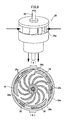
- FIG. 5 is an exploded perspective view of a built-in generator in the faucet device 1.
- FIG. 6 is a cross-sectional, enlarged view of the built-in generator.
- FIG. 7 is a perspective view illustrating a built-in impeller and the associated components in the generator, and
- FIG. 8 is an exploded perspective view thereof.
- FIG. 1 is a block diagram schematically illustrating an internal structure of the faucet device 1 of this embodiment.
- FIG. 3 is a cross-sectional side view of the faucet device 1.
- FIG. 4 is a cross-sectional plane view taken along the line IV-IV of FIG. 3 .
- FIG. 5 is an exploded perspective view of a built-in generator in the faucet device 1.
- FIG. 9 illustrates (a) a perspective view and (b) a cross-sectional view of the built-in impeller in the generator.
- FIG. 10 is a cross-sectional view of a rubber bush for supporting the generator to a device body.
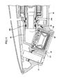
- FIG. 11 is a cross-sectional, enlarged view of an area near the spout port of the faucet device 1.
- the device body 2 is made from metal, and has a base portion 2a fixed to an installation wall 9, and a horizontal portion 2b which is integrally formed with the base portion 2a and extends in a substantially horizontal direction from the upper end of the base portion 2a.
- the base portion 2a is a box type in shape having an approximately square cross-section, and is fixed to the installation wall 9 in a manner to extend in a substantially vertical direction therefrom.
- the horizontal portion 2b is a box type in shape having an opened upper side, extends in a substantially horizontal direction from the upper end of the base portion 2a, and includes a spout port 6 provided on its distal end. Further, the horizontal portion 2b has a cover portion 2e that is detachably attached thereto and covers an opening 2d ( FIG. 12 ) on the upper side of the horizontal portion 2b.
- the device body 2 has a temperature adjusting valve 10, a solenoid valve 12, an impeller-driven generator 14, and a controller 16 built in.
- a filter (not shown) may be provided on the upstream side of the temperature adjusting valve 10.
- a constant flow valve (not shown) may be provided between the solenoid valve 12 and the generator 14.
- the temperature adjusting valve 10 is built in the base portion 2a of the device body 2, to which a hot water supply pipe 18a and a cold water supply pipe 18b are connected.
- the temperature adjusting valve 10 is configured to mix hot water and cold water which are supplied from each supply pipe respectively, based on the setting of the temperature adjusting knob 4, and adjust them to hot and cold water at suitable temperature to be flowed out.
- the temperature adjusting valve 10 is of a commonly-used type so that description of detailed structure thereof is omitted.
- the solenoid valve 12 is built in the base portion 2a of the device body 2, and is connected to the downstream side of the temperature adjusting valve 10 such that the hot and cold water mixed by the temperature adjusting valve 10 flows therein.
- the solenoid valve 12 is configured to open and close based on a control signal sent from the controller 16.
- the solenoid valve 12 is of a commonly-used type so that description of detailed structure thereof is omitted.
- the generator 14 is disposed in the base portion 2a of the device body 2 with being oriented in an approximately horizontal direction.
- the generator 14 is connected such that the hot and cold water that has passed through the solenoid valve 12 flows therein through a solenoid valve-side line 20, and the hot and cold water that has passed through the generator 14 is spouted from the spout port 6 through a spout port-side line 22.
- the electrical power generated by the generator 14 is used to operate the solenoid valve 12, the controller 16, the presence sensor 8, and the like.
- the internal structure of the generator 14 will be described below.
- the controller 16 is configured to generate a control signal for opening and closing the solenoid valve 12 based on a detection signal that is input from the presence sensor 8.
- the controller 16 is made up of a microprocessor, a memory, and programs for operating the microprocessor and the memory, etc. (not shown).
- the generator 14 has a generator water-passage forming member 24, an impeller 26 disposed within the generator water-passage forming member 24, a power generating magnet 28 attached to the impeller 26, an impeller rotary shaft 30 for rotatably supporting the impeller 26, and a power generating coil 32 disposed on the outside of the generator water-passage forming member 24.
- the power generating coil 32, the power generating magnet 28 and a blade 26a of the impeller 26 are disposed in side-by-side relation to each other in this order from the side closer to the spout port 6 along the impeller rotary shaft 30.
- the generator water-passage forming member 24 has a large diameter portion 24a which is an expanded-diameter portion in which an approximately cylindrical water passage is formed, a small diameter portion 24b in which an approximately cylindrical water passage that is narrower than the large diameter portion 24a is formed, and a stepped portion 24c which is a deformation permissive portion by which the large diameter portion 24a is connect to the small diameter portion 24b.
- the large diameter portion 24a and the small diameter portion 24b constitute a generator water passage therein.
- a corner portion 24e at which the large diameter portion 24a and the stepped portion 24c are joined together is applied with an R, i.e., formed to have an arc-shaped cross-section such that the large diameter portion 24a and the stepped portion 24c are smoothly joined. Due to the smoothly joined large diameter portion 24a and the stepped portion 24c at a downstream edge of the large diameter portion 24a, air bubbles that have been pooled in the large diameter portion 24a are smoothly evacuated therefrom to the downstream small diameter portion 24b.
- the corner portion 24e serves as evacuant means for facilitating the evacuation of air bubbles.
- the impeller 26 is rotatably disposed within the large diameter portion 24a.
- the impeller 26 is disposed such that its impeller rotary shaft 30 is in alignment with a central axis of the large diameter portion 24a, and is configured to rotate about the impeller rotary shaft 30 when the hot and cold water flows through the generator water passage.
- the generator water-passage forming member 24 is disposed such that its central axis is oriented to an approximately horizontal direction. For this reason, in the event that outside air enters from the spout port 6 at the time of water stopping of the faucet device 1, the entered air gathers in an air pooling chamber 24d at the inner upper side of the large diameter portion 24a.
- the air pooling chamber 24d is a space located on the uppermost side in the water passage in the device body 2, so that the entered air is floated within the water passage and gathered in the air pooling chamber 24d.
- the small diameter portion 24b is a pipe having a smaller diameter than the large diameter portion 24a, and is formed to have a central axis in alignment with the central axis of the large diameter portion 24a.
- a bearing portion 34 is disposed on the upstream edge of the small diameter portion 24b for supporting the downstream edge side of the impeller rotary shaft 30. Specifically, the bearing portion 34 is disposed adjacent to the stepped portion 24c.
- the stepped portion 24c is formed to connect the large diameter portion 24a to the small diameter portion 24b by a wall surface extending in a direction orthogonal to the central axis.
- the stepped portion 24c is formed to have a thin wall thickness, and is configured to be mainly deformed when a force acts on the generator water-passage forming member 24.
- the bearing portion 34 is an approximately cylindrical member which is fitted inside of the small diameter portion 24b, and has a bearing hole 34a provided on a central axis thereof for receiving the impeller rotary shaft 30 and a plurality of through-holes 34b provided on its periphery for allowing passage of the hot and cold water. As stated above, the bearing portion 34 is disposed adjacent to the stepped portion 24c, thereby to act to limit the amount of deformation of the stepped portion 24c.
- the upstream edge side of the impeller rotary shaft 30 is rotatably supported by a bearing hole 36a provided in the middle of a nozzle casing 36.
- the nozzle casing 36 is a circular shallow cup-like shaped plate and has the bearing hole 36a provided at the center thereof.
- the nozzle casing 36 is an approximately cup-like shaped member disposed within the large diameter portion 24a in a manner to obstruct the central region of the water passage.
- the hot and cold water that has flowed from the upstream side into the large diameter portion 24a is guided by the nozzle casing 36 to the periphery of the large diameter portion 24a, and flows through a gap between an outer periphery of the nozzle casing 36 and an inner wall surface of the large diameter portion 24a to the downstream side. Then, the hot and cold water flows from an injection port 36b provided on the lateral side of the nozzle casing 36 toward the center of the large diameter portion 24a to rotate the impeller 26. Specifically, the injection port 36b injects the water from the periphery of the large diameter portion 24a toward the impeller 26.
- the metallic impeller rotary shaft 30 extends from the nozzle casing 36 to the bearing hole 34a through the impeller 26 in a manner to go across the stepped portion 24c. For this reason, the amount of deformation of the stepped portion 24c is limited by the impeller rotary shaft 30.
- the impeller 26 is an approximately cylindrical member, to which the impeller rotary shaft 30 is attached along the central axis of the impeller 26.
- the blade 26a is provided on the upstream edge side of the impeller 26, so that the impeller 26 is rotated by the flow of hot and cold water from the peripheral edge to the center of the nozzle casing 36.
- an axially penetrating impeller water-passage 26b is provided within the impeller water-passage 26b, so that the hot and cold water gathered from the peripheral edge to the center passes through the impeller water-passage 26b and flows into the small diameter portion 24b.
- the outer periphery of the impeller 26 has a reduced diameter on the downstream side thereof, and the annular power generating magnet 28 is attached to the reduced diameter portion. Therefore, when the power generating magnet 28 is projected to the direction of the impeller rotary shaft 30, the projection overlaps with a part of the blade 26a of the impeller 26. Specifically, the power generating magnet 28 and the blade 26a of the impeller 26 partially overlap with each other in the projection to the direction of the impeller rotary shaft 30.
- each injection port 36b is provided equiangularly on the lateral side of the nozzle casing 36.
- each injection port 36b is formed at regular intervals in a circumferential direction of a circle centered on the impeller rotary shaft 30.
- the hot and cold water is injected from the injection port 36b to a substantially tangential direction of the outer circumference of the impeller 26, and hits against the blade 26a of the impeller 26 in a direction orthogonal to the impeller rotary shaft 30 to rotate the impeller 26.
- the hot and cold water that has hit against the blade 26a flows toward the center of the impeller 26 before flowing into the impeller water-passage 26b at the center of the impeller 26, and flows through the impeller water-passage 26b in a horizontal direction.
- the power generating magnet 28 is constructed in an approximately annular shape, and has an N-pole and an S-pole alternately formed along the circumference thereof.
- the power generating coil 32 is constructed in an annular shape, and is disposed to surround the small diameter portion 24b of the generator water-passage forming member 24. Further, the upstream edge of the power generating coil 32 abuts the stepped portion 24c of the generator water-passage forming member 24. The abutment of the power generating coil 32 against the stepped portion 24c limits the amount of deformation of the stepped portion 24c (deformation permissive portion) in the event of vibration of the generator 14.
- the power generating coil 32 and the power generating magnet 28 are disposed in side-by-side relation to each other in an axial direction of the generator water-passage forming member 24, where the rotation of the power generating magnet 28 along with the impeller 26 develops electromotive force in the power generating coil 32.
- the impeller 26, the power generating magnet 28 and the power generating coil 32 are disposed in this order from the upstream side in the generator 14.
- the generator 14 has a waterproof cover 38 and a pole piece 40.
- the waterproof cover 38 is an approximately cylindrical member which is attached to cover a part of the generator water-passage forming member 24.
- the waterproof cover 38 extends from an area on the upstream side of the small diameter portion 24b to an area on the downstream side of the large diameter portion 24a and disposed to cover a part thereof.
- the power generating coil 32 and the pole piece 40 are contained in a space between an external surface of the generator water-passage forming member 24 and an internal surface of the waterproof cover 38 to prevent the position gap of the pole piece 40 in the event of vibration of the generator 14.
- the waterproof cover 38 is dimensioned such that the power generating coil 32 is sandwiched and fixed between the waterproof cover 38 and the stepped portion 24c of the generator water-passage forming member 24.
- An O-ring is disposed between the waterproof cover 38 and the large diameter portion 24a, as well as between the waterproof cover 38 and the small diameter portion 24b respectively, and is adapted to prevent the hot and cold water from entering into the waterproof cover 38.
- the waterproof cover 38 is disposed over an area from the small diameter portion 24b to the large diameter portion 24a in a manner to go across the stepped portion 24c, so that the amount of deformation of the stepped portion 24c in the event of vibration of the generator 14 is limited.
- the pole piece 40 is constructed from a thin plate of a magnetic material, and is formed to surround the inner and outer periphery sides of the power generating coil 32. Further, the pole piece 40 has a plurality of pawls 40a which extend to surround an area from the power generating coil 32 to the large diameter portion 24a. Each pawl 40a extends in an axial direction of the large diameter portion 24a in a manner to contact with the outer periphery of the large diameter portion 24a.
- the pawls 40a would extend from the power generating coil 32 to the periphery of the power generating magnet 28, so that the magnetism of the power generating magnet 28 is induced to the power generating coil 32 via the pawls 40a of the pole piece 40.
- the pole piece 40 and the power generating magnet 28 are disposed to be opposed to each other in a radial direction of a circle centered on the impeller rotary shaft 30, and transmit the magnetism to a radial direction of this circle.
- each pawl 40a of the pole piece 40 extends to surround the large diameter portion 24a, and thus the amount of deformation of the stepped portion 24c is limited by the pole piece 40.
- a fixation structure of the generator 14 will now be described with reference to FIGS. 3 , 4 , 10 and 11 .
- a spout port-side water-passage forming member 42 is connected to a distal end of the small diameter portion 24b of the generator water-passage forming member 24.
- the spout port-side water-passage forming member 42 serves as a spout port-side line 22 ( FIG. 2 ).
- a spout port-side support bracket 42a is formed on both sides of the spout port-side water-passage forming member 42.
- a packing (gasket) 42b is disposed between the spout port-side water-passage forming member 42 and the small diameter portion 24b to ensure water-tightness between the small diameter portion 24b and the spout port-side water-passage forming member 42.
- the packing (gasket) 42b allows slight relative displacement between the small diameter portion 24b of the generator 14 and the spout port-side water-passage forming member 42.
- the packing (gasket) 42b serves as a second elastic member.
- a spout port forming ring 44 as a spout port forming portion and a flow rectifying member 46 are attached to a distal end of the spout port-side water-passage forming member 42.
- the spout port forming ring 44 is a cylindrical member, and the hot and cold water that has passed through the spout port-side water-passage forming member 42 is spouted through inside of the spout port forming ring 44.
- the spout port forming ring 44 is disposed on the inner side of a spout port disposing aperture 2c that is provided on the distal end of the device body 2.
- a gap is provided between the spout port disposing aperture 2c and the spout port forming ring 44, and the spout port forming ring 44 is fixed to be out of contact with the device body 2.
- the lower end of the spout port forming ring 44 is positioned with being retracted more to the inner side than the spout port disposing aperture 2c.
- the gap between the outer periphery of the spout port forming ring 44 and the spout port disposing aperture 2c is covered with a gap cover 48.
- the spout port-side water-passage forming member 42 is in contact with the device body 2 via a support packing (gasket) 50 as a supporting point forming member. In this way, the spout port-side water-passage forming member 42 is elastically supported by the support packing (gasket) 50.
- a stepped cylindrical first solenoid valve-side water-passage forming member 52 and a second solenoid valve-side water-passage forming member 54 are inserted into the large diameter portion 24a of the generator water-passage forming member 24, and a third solenoid valve-side water-passage forming member 56 is connected to the second solenoid valve-side water-passage forming member 54.
- the first, second and third solenoid valve-side water-passage forming members 52, 54 and 56 serve as a solenoid valve-side line 20.
- the upstream edge of the third solenoid valve-side water-passage forming member 56 contains the temperature adjusting valve 10 and the solenoid valve 12, and is connected to a base member 59 disposed within the base portion 2a.
- a solenoid valve-side support bracket 56a is provided on the third solenoid valve-side water-passage forming member 56.
- a packing (gasket) 52a is disposed between the large diameter portion 24a and the first solenoid valve-side water-passage forming member 52
- a packing (gasket) 54a is disposed between the first solenoid valve-side water-passage forming member 52 and the second solenoid valve-side water-passage forming member 54
- a packing (gasket) 56b is disposed between the second solenoid valve-side water-passage forming member 54 and the third solenoid valve-side water-passage forming member 56, to ensure water-tightness between these members.
- the packing (gasket) 52a allows slight relative displacement between the large diameter portion 24a of the generator 14 and the first solenoid valve-side water-passage forming member 52, and ensures water-tightness therebetween.
- the packing (gasket) 54a allows slight relative displacement between the first solenoid valve-side water-passage forming member 52 and the second solenoid valve-side water-passage forming member 54, and ensures water-tightness therebetween.
- the packing (gasket) 56b allows slight relative displacement between the second solenoid valve-side water-passage forming member 54 and the third solenoid valve-side water-passage forming member 56, and ensures water-tightness therebetween.
- the packings (gaskets) 52a, 54a and 56b serve as a first elastic member.
- the spout port-side line 22 includes a packing (gasket) 42b disposed between the spout port-side water-passage forming member 42 and the small diameter portion 24b, while the solenoid valve-side line 20 includes packings (gaskets) 52a, 54a and 56b disposed between each solenoid valve-side water-passage forming member.
- the solenoid valve-side line 20 has larger room for deformation by the packings (gaskets) than the spout port-side line 22, and the solenoid valve-side line 20 is configured to be more easily deformable than the spout port-side line 22.
- connection between the small diameter portion 24b of the generator water-passage forming member 24 and the spout port-side water-passage forming member 42 via the packing (gasket) 42b serves as a flection allowing portion for allowing flection between the spout port-side line 22 and the generator 14.
- FIG. 10(a) is a cross-sectional view illustrating a supporting structure of the spout port-side support bracket 42a of the spout port-side water-passage forming member 42
- FIG. 10(b) is a cross-sectional view illustrating a supporting structure of the solenoid valve-side support bracket 56a of the third solenoid valve-side water-passage forming member 56.
- the generator 14 is mounted in the device body 2 via the spout port-side support bracket 42a of the spout port-side water-passage forming member 42 and the solenoid valve-side support bracket 56a of the third solenoid valve-side water-passage forming member 56 which are separate members from the generator 14. Further, between the mounted generator 14 and an inner wall surface of the device body 2, namely between the generator 14 and an inner wall surface of the horizontal portion 2b as well as between the generator 14 and a back surface of the cover portion 2e, space is formed all over the periphery of the generator 14. This allows vibration of the generator 14 and prevents generation of abnormal noise caused by the vibrating generator 14 directly hitting against the device body 2.
- the spout port-side support bracket 42a is attached to the device body 2 by a screw 58a via a spout port-side rubber bush as a fourth elastic member.
- the solenoid valve-side support bracket 56a is attached to the device body 2 by a screw 60a via a solenoid valve-side rubber bush 60 as a third elastic member.
- the spout port-side rubber bush 58 and the solenoid valve-side rubber bush 60 are disposed on substantially the same level. Specifically, a straight line connecting the spout port-side rubber bush 58 and the solenoid valve-side rubber bush 60 is oriented in a substantially horizontal direction.
- the spout port-side rubber bush 58 and the solenoid valve-side rubber bush 60 constitute vibration excitation means.
- the generator 14 is supported in a condition which is very likely to be vibrated by the spout port-side rubber bush 58 and the solenoid valve-side rubber bush 60.
- the power generating magnet 28 is rotated along with the impeller 26, which produces a relative rotation to the fixed power generating coil 32. This develops electromotive force in the power generating coil 32, and electromagnetic force in a direction orthogonal to the impeller rotary shaft 30 between the power generating magnet 28 and the power generating coil 32.
- this electromagnetic force varies depending on a relative rotational position between the power generating magnet 28 and the power generating coil 32, the electromagnetic force vibrationally varies with the rotation of the power generating magnet 28. Due to a synergistic effect of this vibrational force and the support by the vibration excitation means of the generator 14, vibration in a direction orthogonal to the impeller rotary shaft 30 is excited in the generator 14. In particular, in this embodiment, variation in the developed electromagnetic force is made to be large by employing a single-layer coil as the power generating coil 32, thereby the vibration of the generator 14 can be effectively excited.
- the spout port-side rubber bush 58 is formed of an upper surface portion 58b which is located on an upper surface of the spout port-side support bracket 42a as a support bracket, a lower surface portion 58c which is located on a lower surface of the spout port-side support bracket 42a, and a peripheral portion 58d which is located around the screw 58a.
- the upper surface portion 58b is a portion which is wedged between the upper surface of the spout port-side support bracket 42a and a head of the screw 58a
- the lower surface portion 58c is a portion which is wedged between the lower surface of the spout port-side support bracket 42a and the horizontal portion 2b of the device body 2.
- the peripheral portion 58d is a portion which is wedged between a shaft portion of the screw 58a and an inner wall surface of a hole of the spout port-side support bracket 42a.
- the generator 14 and the spout port-side water-passage forming member 42 are displaced in a vertical direction, the upper surface portion 58b and the lower surface portion 58c of the spout port-side rubber bush 58 are mainly subjected to elastic deformation.
- the peripheral portion 58d of the spout port-side rubber bush 58 is mainly subjected to elastic deformation.
- thickness of the upper surface portion 58b and the lower surface portion 58c of the spout port-side rubber bush 58 is greater than thickness of the peripheral portion 58d, and thus the spout port-side support bracket 42a is more likely to be displaced in a vertical direction than in a horizontal direction.
- the amount of displacement of the spout port-side support bracket 42a in the case of pressing it in a vertical direction is greater than that in the case of pressing it in a horizontal direction with the same power.
- an annular protrusion 58e having a triangle cross-section is formed at the position fitting together with the spout port-side support bracket 42a.
- the spout port-side support bracket 42a is also displaced in a vertical direction even when it is pressed in a horizontal direction.
- the peripheral portion 58d is slid upwardly or downwardly on a slope of the protrusion 58e by a horizontal pressing force, which produces vertical displacement in the spout port-side support bracket 42a. Therefore, even when a horizontal excitation force acts on the spout port-side support bracket 42a, a part of the excitation force is converted to a vertical direction and vibration having vertical components is excited in the spout port-side support bracket 42a.
- the solenoid valve-side rubber bush 60 is formed of an upper surface portion 60b which is located on an upper surface of the solenoid valve-side support bracket 56a as a support bracket, a lower surface portion 60c which is located on a lower surface of the solenoid valve-side support bracket 56a, and a peripheral portion 60d which is located around the screw 60a.
- the generator 14 and the third solenoid valve-side water-passage forming member 56 are displaced in a vertical direction, the upper surface portion 60b and the lower surface portion 60c of the solenoid valve-side rubber bush 60 are mainly subjected to elastic deformation.
- the generator 14 and the third solenoid valve-side water-passage forming member 56 are displaced in a horizontal direction, the peripheral portion 60d of the solenoid valve-side rubber bush 60 is mainly subjected to elastic deformation.
- thickness of the upper surface portion 60b and the lower surface portion 60c of the solenoid valve-side rubber bush 60 is greater than thickness of the peripheral portion 60d, and thus the solenoid valve-side support bracket 56a is more likely to be displaced in a vertical direction than in a horizontal direction.
- the amount of displacement of the solenoid valve-side support bracket 56a in the case of pressing it in a vertical direction is greater than that in the case of pressing it in a horizontal direction with the same power.
- an annular protrusion 60e having a triangle cross-section is formed at the position fitting together with the solenoid valve-side support bracket 56a.
- the solenoid valve-side support bracket 56a is also displaced in a vertical direction even when it is pressed in a horizontal direction.
- the peripheral portion 60d is slid upwardly or downwardly on a slope of the protrusion 60e by a horizontal pressing force, which produces vertical displacement in the solenoid valve-side support bracket 56a.
- the upper surface portion 60b and the lower surface portion 60c of the solenoid valve-side rubber bush 60 are formed to have larger thickness than the upper surface portion 58b and the lower surface portion 58c of the spout port-side rubber bush 58. Therefore, a force required to cause a certain amount of elastic deformation is smaller in the solenoid valve-side rubber bush 60 than in the spout port-side rubber bush 58. In other words, configuration is made such that a force required to cause an upward or downward displacement by a certain distance is smaller in the solenoid valve-side support bracket 56a than in the spout port-side support bracket 42a.
- the generator 14 is supported to be vibrated more largely on the upstream side which is closer to the solenoid valve 12 than on the downstream side which is closer to the spout port 6.
- the spout port-side rubber bush 58 and the solenoid valve-side rubber bush 60 is configured to have a greater amount of deformation than the packings (gaskets) 52a, 54a and 56b and the packing (gasket) 42b.
- the blade 26a of the impeller 26 is located at a position closer to the solenoid valve-side rubber bush 60 than the spout port-side rubber bush 58, and thus the generator 14 is more likely to be vibrated on its upstream side.
- the spout port-side rubber bush 58 and the solenoid valve-side rubber bush 60 are configured mainly to allow vertical vibration of the generator 14.
- the support packing (gasket) 50 which provides an elastic support for the spout port-side water-passage forming member 42 is disposed on a plane inclined with respect to a horizontal direction.
- the support packing (gasket) 50 acts mainly to allow vibration in a direction which is inclined with respect to a vertical direction, and constrains the vibration in a vertical direction as compared to the vibration in this inclined direction.
- the generator 14 vibrates based approximately on the support packing (gasket) 50 as a supporting point, and an amplitude of vertical vibration of the generator 14 becomes larger in a direction further from the support packing (gasket) 50.
- This vertical vibration is allowed by the spout port-side rubber bush 58 and the solenoid valve-side rubber bush 60.
- the vibration on the downstream side of the support packing (gasket) 50 is not constrained because the spout port forming ring 44 which is attached to the downstream side of the spout port-side water-passage forming member 42 keeps a gap with respect to the spout port disposing aperture 2c and is attached to be out of contact with the device body 2.
- the lower end of the spout port forming ring 44 is located at a position closer to the support packing (gasket) 50 than the generator 14, and thus an amplitude of vibration based on the support packing (gasket) 50 as a supporting point is greater in the generator 14 than in the lower end of the spout port forming ring 44.
- FIG. 12 is a perspective view illustrating the situation where a cover portion 2e is removed from a horizontal portion 2b of the device body 2.
- the first solenoid valve-side water-passage forming member 52, the second solenoid valve-side water-passage forming member 54 and the third solenoid valve-side water-passage forming member 56 are attached to the upstream side of the generator 14, respectively through the intermediary of a packing (gasket) between each member.
- the spout port-side water-passage forming member 42 is attached via a packing (gasket).
- a unit including the generator 14 that is assembled in this way is disposed and mounted within the horizontal portion 2b through the opening 2d on the upper side of the horizontal portion 2b.
- the lower end portion of the third solenoid valve-side water-passage forming member 56 is inserted into the base member 59 via an O-ring.
- the support packing (gasket) 50 ( FIG. 11 ) is disposed between the spout port-side water-passage forming member 42 and the horizontal portion 2b.
- the spout port-side support bracket 42a is fixed by the screw 58a to the horizontal portion 2b
- the solenoid valve-side support bracket 56a is fixed by the screw 60a to the horizontal portion 2b.
- the spout port-side water-passage forming member 42 is detachably coupled to the horizontal portion 2b via the spout port-side rubber bush 58
- the third solenoid valve-side water-passage forming member 56 is detachably coupled to the horizontal portion 2b via the solenoid valve-side rubber bush 60.
- FIG. 13 is a cross-sectional view illustrating the situation where the faucet device 1 is installed on an installation wall 9.
- the faucet device 1 is fixed by a fixing shaft 62, a fastener member 64, a fixing nut 64a, a topside elastic mount member 66, and a backside elastic mount member 68.
- the fixing shaft 62 is provided with a screw thread and is threadingly received by the base member 59 in the device body 2.
- the fastener member 64 is a C-shaped member to be disposed to surround a mounting hole 9a provided in the installation wall 9, in which a bore 62a for permitting the passage of the fixing shaft 62 is provided.
- the topside elastic mount member 66 is an annular elastic member to be disposed on the installation wall 9.
- the backside elastic mount member 68 is an annular elastic member to be disposed on the back side of the installation wall 9.
- the fixing shaft 62 is attached to the base member 59 in the device body 2.
- the topside elastic mount member 66 is disposed on the upper surface of the installation wall 9, and then the faucet device 1 is disposed on the installation wall 9 in a manner to cause the fixing shaft 62 to be passed through the mounting hole 9a formed in the installation wall 9.
- the topside elastic mount member 66 is sandwiched between the bottom surface of the base portion 2a and the installation wall 9.
- the backside elastic mount member 68 is disposed on the backside of the installation wall 9 in a manner to surround the mounting hole 9a.
- the backside elastic mount member 68 is held from the downside in a manner to cause the fixing shaft 62 to be passed through the bore 62a of the fastener member 64.
- the fixing nut 64a is threadingly received by the fixing shaft 62, and the fastener member 64 is tightened up.
- the topside elastic mount member 66 is sandwiched between the bottom surface of the base portion 2a and the upper surface of the installation wall 9, and the backside elastic mount member 68 is sandwiched between the lower surface of the installation wall 9 and the fastener member 64.
- vibration propagated from the bottom surface of the base portion 2a to the installation wall 9 is suppressed by the topside elastic mount member 66, and vibration propagated from the base portion 2a to the installation wall 9 via the fixing shaft 62 and the fastener member 64 is suppressed by the backside elastic mount member 68.
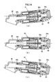
- FIG. 14 schematically illustrates a displacement among the generator 14, a spout port-side water-passage forming member 42, a first solenoid valve-side water-passage forming member 52, and a second solenoid valve-side water-passage forming member 54.
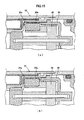
- FIG. 15 illustrates the condition of air pooled in an air pooling chamber 24d.
- FIG. 16 schematically illustrates a pathway through which air pooled in an air pooling chamber 24d is evacuated.
- the presence sensor 8 detects it and sends a signal to the controller 16.
- the controller 16 sends a signal to the solenoid valve 12 and switches it to an open state.
- the solenoid valve 12 is opened, hot water and cold water which are supplied from the hot water supply pipe 18a and the cold water supply pipe 18b are respectively supplied to the temperature adjusting valve 10.
- the supplied hot water and cold water are mixed within the temperature adjusting valve 10, and flows as indicated by an arrow in FIG. 3 to reach the generator 14.
- the supplied hot water and cold water are adjusted by the temperature adjusting valve 10 to a temperature set by the temperature adjusting knob 4, and then flow out.
- the hot and cold water that has flowed out from the temperature adjusting valve 10 passes through the solenoid valve 12 which is in an open state.
- the hot and cold water that has passed through the solenoid valve 12 flows inside of the third solenoid valve-side water-passage forming member 56, the second solenoid valve-side water-passage forming member 54 and the first solenoid valve-side water-passage forming member 52 which constitute the solenoid valve-side line 20, and then reaches the generator 14. Then, the hot and cold water that has flowed into the large diameter portion 24a of the generator water-passage forming member 24 flows around the nozzle casing 36 which is disposed in the central region of the large diameter portion 24a, and is injected from the side-on injection port 36b in a direction orthogonal to the impeller rotary shaft 30 to hit against the blade 26a of the impeller 26 from the lateral side.
- the hot and cold water that has passed the generator 14 flows into the spout port-side water-passage forming member 42 constituting the spout port-side line 22, passes through the spout port forming ring 44 and the flow rectifying member 46 which are coupled to the spout port-side water-passage forming member 42, and then spouted from the spout port 6.
- the power generating magnet 28 attached to the impeller 26 is rotated with a rotation of the impeller 26, so that the magnetic field formed around the power generating magnet 28 is changed.
- This change in the magnetic field is induced by the pole piece 40 to the power generating coil 32, developing electromotive force in the power generating coil 32.
- electromagnetic force acts between the power generating magnet 28 and the pole piece 40, which varies with the rotation of the impeller 26.
- This variation in the electromagnetic force becomes one of vibration sources for producing vibration in the generator 14.
- electrical power generated by the generator 14 is charged in a built-in charger (not shown) in the controller 16, and used for opening and closing of the solenoid valve 12, for operation of the presence sensor 8, and for operation of the controller 16 itself.
- the controller 16 send a signal to the solenoid valve 12 and switches it to a closed state.
- gravity would act on the hot and cold water within the solenoid valve-side line 20, the spout port-side line 22 and the generator water-passage forming member 24 which are the water passage on the downstream side of the solenoid valve 12, and would prompt the hot and cold water to flow down from the spout port 6 that is located below the water passage.
- the spout port 6 includes the flow rectifying member 46 disposed therein, which is adapted to cause the hot and cold water that is to be flowed out from the spout port 6 to be flowed out through a large number of fine pores provided on the flow rectifying member 46. For this reason, surface tension acts against the gravity which prompts the inner hot and cold water to flow down, by which the outflow of the hot and cold water within the water passage is suppressed.
- a part of the hot and cold water within the water passage flows out through the fine pores on the flow rectifying member 46, and outside air enters into the water passage as substitute for the hot and cold water that has flowed out.
- the hot and cold water within the water passage is also reduced by being evaporated into the outside air.
- the outside air that has entered into the water passage is floated and moved up as bubbles within the water passage.
- the entered outside air is gathered in the air pooling chamber 24d ( FIG. 3 ) that is an upper portion of the large diameter portion 24a and is a space located on the uppermost side in the water passage.
- the air that has entered into the water passage, especially inside of the generator 14, causes a negative effect on the operation of the generator 14, and lowers the power generation efficiency or renders the electric-generating capacity unstable.
- the entered air may generate abnormal noise from the generator 14, or it may shorten the life of the generator 14 in the case of having a significant effect.
- the total amount thereof is not easily extruded by the hot and cold water flowing inside even after switched to a water spouting state, and the air remains pooled in the generator 14 in a conventional faucet device.
- the generator 14 is configured to easily vibrate relative to the device body 2 by the spout port-side rubber bush 58 and the solenoid valve-side rubber bush 60.
- the packing (gasket) 42b is disposed between the generator 14 and the spout port-side water-passage forming member 42, and the packings (gaskets) 52a, 54a and 56b are disposed between the generator 14 and the third solenoid valve-side water-passage forming member 56 respectively, and these packings (gaskets) allow relative displacement between the generator 14 and each water-passage forming member.
- the generator 14 and the members connected thereto are vibrated as illustrated in FIG. 14 . It is noted that the amount of displacement in FIG. 14 is depicted with exaggeration.
- These rubber bushes and packings suppress the propagation of vibration to the device body 2 which is excited in the generator 14 by the electromagnetic force acting between the power generating magnet 28 and the pole piece 40 as well as by the flow of hot and cold water inside the generator 14, when the faucet device 1 is switched to the water spouting state.
- the topside elastic mount member 66 suppresses the propagation of vibration of the device body 2 to the installation wall 9.
- the backside elastic mount member 68 prevents the vibration of the device body 2 from being propagated to the fixing shaft 62 and the fastener member 64 to cause vibration of the installation wall 9. In this way, generation of abnormal noise caused by the vibration of the generator 14 which is propagated to the device body 2 and the installation wall 9 is suppressed.
- vibration of the generator 14 facilitates the evacuation of air, which is pooled inside, along with the hot and cold water flowing inside.
- the air in the generator 14 floats in the large diameter portion 24a, and is gathered and pooled near the inner wall surface on the upper side of the large diameter portion 24a located on the vertically uppermost side. In such an area near the inner wall surface, the flow rate of the hot and cold water flowing through the large diameter portion 24a is slow, and thus the air is not easily evacuated even if the hot and cold water flows through the generator 14.
- the generator 14 when the generator 14 is vertically vibrated, the air bubbles that have been pooled near the inner wall surface are drawn away from the wall surface and moved near the center of the flow path.
- the air bubbles When the air bubbles are drawn away from the inner wall surface, they are evacuated from the generator 14 by the hot and cold water flowing through the large diameter portion 24a because the flow rate is relatively high in the area distant from the wall surface.
- the spout port-side rubber bush 58 and the screw 58a, as well as the solenoid valve-side rubber bush 60 and the screw 60a act to convert the horizontal excitation force to vertical vibration components, and thus vibration including a number of vertical components is excited in the generator 14.
- the corner portion 24e at a downstream edge of the large diameter portion 24a is formed to have an arc-shaped cross-section, and thus it facilitates the evacuation of air bubbles made by the flow of hot and cold water passing the outside of the impeller 26.
- the hot and cold water that has flowed into the generator 14 is injected from the injection port 36b on the side of the nozzle casing 36 and hits against the blade 26a of the impeller 26.
- This flow of hot and cold water from the injection port 36b toward the center of the impeller 26 causes the air bubbles in the large diameter portion 24a to move to the central region of the impeller 26.
- the air bubbles in the large diameter portion 24a are evacuated to the outside of the generator 14 through the impeller water-passage 26b of the impeller 26.
- the solenoid valve-side rubber bush 60 is configured to be more likely to allow the vibration than the spout port-side rubber bush 58, and thus the upstream side of the generator 14 on which the large diameter portion 24a is positioned is more largely vibrated than the downstream side. This facilitates the evacuation of air in the large diameter portion 24a.
- the impeller 26 which is relatively light in weight is disposed on the upstream side of the generator 14, while the power generating coil 32 and the power generating magnet 28 which are heavy in weight are disposed on the downstream side, and thus the upstream side of the generator 14 is likely to be vibrated with larger amplitude than the downstream side.
- the solenoid valve-side line 20 and the spout port-side line 22 which are connected to the generator 14 are configured to have the packings (gaskets) 52a, 54a and 56b which are interposed between each member, while the spout port-side line 22 is only provided with the packing (gasket) 42b, so that the solenoid valve-side line 20 is more likely to be deformed.
- the spout port side of the generator 14 is connected to the separately constituted spout port-side water-passage forming member 42, and is supported to the device body 2 by the spout port-side rubber bush 58 via the spout port-side support bracket 42a provided on the spout port-side water-passage forming member 42.
- the solenoid valve side of the generator 14 is connected to the separately constituted third solenoid valve-side water-passage forming member 56, and is supported to the device body 2 by the solenoid valve-side rubber bush 60 via the solenoid valve-side support bracket 56a provided on the third solenoid valve-side water-passage forming member 56.
- the amount of deformation becomes larger in a direction from the spout port-side line 22 on the downstream side to the solenoid valve-side line 20 on the upstream side of the generator 14.
- the vibration of the generator 14 also causes the vibration of the spout port-side line 22 connected thereto, but the vibration of the generator 14 is not interrupted by the spout port forming ring 44 attached to a distal end of the spout port-side line 22 because the spout port forming ring 44 is disposed on the spout port-side line 22 in a manner to be out of contact with the device body 2.
- the spout port-side water-passage forming member 42 constituting the spout port-side line 22 is elastically supported to the device body 2 by the support packing (gasket) 50.
- the vibration of the generator 14 will be the vertical one based approximately on the support packing (gasket) 50 as a supporting point.
- the spout port forming ring 44 is disposed at a position closer to the support packing (gasket) 50 than the generator 14, and thus the vibration based on the support packing (gasket) 50 as a supporting point has a relatively small amplitude on the side of the spout port forming ring 44, so that even when the generator 14 is largely vibrated, the flow of hot and cold water spouted from the spout port forming ring 44 is not deflected largely.
- the packing (gasket) 42b is disposed between the large diameter portion 24a of the generator 14 and the spout port-side water-passage forming member 42 to form a flection allowing portion.
- a part of vibration of the generator 14 is absorbed by the flection allowing portion, thereby the vibration propagated from the generator 14 to the spout port forming ring 44 is decreased to reduce deflection of the spout port forming ring 44.
- the spout port forming ring 44 is disposed with being retracted more to the inner side than the spout port disposing aperture 2c of the device body 2, and thus even if the spout port forming ring 44 is vibrated, it is difficult to visibly recognize this vibration, and the appearance of the faucet device 1 is not detracted. Further, the gap between the spout port forming ring 44 and the spout port disposing aperture 2c is covered with the gap cover 48, so that even if the gap is present between the device body 2 and the spout port forming ring 44, it does not detract the appearance of the faucet device 1, and the vibration of the spout port forming ring 44 is hidden from the outside.
- the generator water-passage forming member 24 is affected by a force which deforms it.
- this force is likely to concentrate on the stepped portion 24c which connects the large diameter portion 24a to the small diameter portion 24b, but the stress acting on the generator water-passage forming member 24 is escaped by configuring this stepped portion 24c to be deformable as a deformation permissive portion.
- excessive deformation of the stepped portion 24c may lead to destruction of generator water-passage forming member 24, and thus the power generating coil 32 is disposed adjacent to the stepped portion 24c to prevent the excessive deformation of the stepped portion 24c.
- the pawls 40a of the pole piece 40 are disposed in a manner to go across the stepped portion 24c, thereby the amount of deformation of the stepped portion 24c is limited.
- the bearing portion 34 is fitted inside of the small diameter portion 24b that is adjacent to the stepped portion 24c, and thus the amount of deformation of inner periphery of the stepped portion 24c is limited.
- the impeller rotary shaft 30 of the impeller 26 is also disposed in a manner to go across the stepped portion 24c, thereby the amount of deformation of the stepped portion 24c is limited.
- the waterproof cover 38 covers the power generating coil 32 and the pole piece 40 and is disposed in a manner to cover the large diameter portion 24a and the small diameter portion 24b provided on both sides of the stepped portion 24c, and thus the deformation of the stepped portion 24c is also limited by the waterproof cover 38.
- the solenoid valve side of the generator 14 is coupled to the device body 2 via the packings (gaskets) 52a, 54a and 56b and the solenoid valve-side rubber bush 60, and the spout port side of the generator 14 is coupled to the device body 2 via the packing (gasket) 42b and the spout port-side rubber bush 58, and thus the vibration propagated to the device body 2 can be sufficiently suppressed and the generated abnormal noise can also be suppressed. It is noted that when it is sought to ensure a large vibration stroke for suppressing the propagation of vibration only with the seal material between the generator and the water-passage forming member, the vibration of the generator would develop a seal defect which results in water leak and decreased durability of the seal material.
- the propagation of the vibration is suppressed in two stages: one by the packings (gaskets) disposed between the generator and the water-passage forming member connected thereto, and one by the rubber bushes disposed between the connected water-passage forming member and the device body 2.
- This allows the packings (gaskets) for ensuring water-tightness to be utilized for suppression of vibration, while sufficiently suppressing the propagation of vibration. Further, ensuring of the vibration stroke is performed in two stages, so that decrease in water-tightness and degradation of stability of the packings (gaskets) can be avoided.
- the spout port-side rubber bush 58 and the solenoid valve-side rubber bush 60 excite vibration having vertical components by a horizontal excitation force, and thus the vibration of the generator would be larger in a vertical direction and smaller in a horizontal vibration.
- the vibration is mainly of the same vertical direction as the direction in which the spouted water flows, and is less recognizable by a user relative to the case in which it is vibrated in a horizontal direction. This makes it possible to sufficiently suppress the propagation of vibration of the generator 14, while reducing disturbance in the stream of water which is recognizable by the user to allow the faucet device 1 to have an improved quality level.
- the straight line connecting the spout port-side rubber bush 58 and the solenoid valve-side rubber bush 60 is oriented toward a substantially horizontal direction, so that vertical vibrational components of the generator 14 can be further increased and disturbance in the stream of water which is recognizable by the user can be reduced more.
- the solenoid valve-side rubber bush 60 is formed to be more susceptible to the deformation, thereby the vibration of the generator 14 becomes larger in a direction to the side closer to the solenoid valve 12, and thus disturbance in the streams of spouted water can be reduced. Further, vibration of the device body 2 can be better suppressed because vibration is reduced on the spout port side which is closer to the distal end of the device body 2b and is difficult to ensure the rigidity.
- the blade 26a of the impeller 26 is disposed on the side closer to the solenoid valve-side rubber bush 60, and thus the impeller 26, which would be a source of vibration due to the action of electromagnetic force at the time of electrical power generation, does not strongly excite the distal end of the horizontal portion 2b, so that vibration of the device body 2 can be better suppressed.
- the impeller and the power generating magnet 28 is disposed in side-by-side relation to each other along the impeller rotary shaft 30, and the power generating magnet 28 is formed to have a similar size of diameter to the blade 26a of the impeller 26, and thus the moment of inertia of the rotating portion of the generator can be decreased as compared to the conventional generators in which a power generating magnet is disposed on the radially outer side of a blade of the impeller.
- This makes it possible to improve the power generation efficiency of the generator 14, decrease the magnetic flux density of the power generating magnet 28 which is necessary to achieve power requirements, and suppress the generation of vibration.
- the power generating coil 32, the power generating magnet 28 and the blade 26a of the impeller 26 are disposed in this order from the side closer to the spout port within the generator 14, and thus the blade 26a which would be a source of vibration is located at a position distant from the spout port 6 so that it does not strongly excite the distal end of the horizontal portion 2a, and vibration of the device body 2 can be better suppressed.
- magnetism of the power generating magnet 28 is guided by the pole piece 40 to the power generating coil 32, and thus the power generating magnet 28 can be disposed on the downstream side of the power generating coil 32, which enables the blade 26a as a source of vibration to be provided at a position further distant from the spout port 6.
- the base portion 2a and the horizontal portion 2b of the device body 2 are made from metal and are integrally formed, and thus they are highly rigid and less likely to be vibrated by the vibration of the generator 14, so that the generation of abnormal noise can be suppressed.
- the horizontal portion 2b is formed with an opening 2d on the upper side thereof, through which a unitization of assembled generator 14, spout port-side water-passage forming member 42, first to third solenoid valve-side water-passage forming member 52, 54 and 56, spout port-side rubber bush 58 and solenoid valve-side rubber bush 60 can be inserted and mounted, enabling an easy assembly of the faucet device 1.
- Such a structure of the device body 2 satisfies both of suppression of abnormal noise and improvement of assembly.
- the solenoid valve-side rubber bush 60 is formed to be more susceptible to the deformation, thereby the vibration of the generator 14 becomes larger in a direction to the side closer to the solenoid valve 12, and thus disturbance in the streams of spouted water can be reduced. Further, vibration of the device body 2 can be better suppressed because vibration is reduced on the spout port side which is closer to the distal end of the device body 2b and is difficult to ensure the rigidity.
- the blade 26a of the impeller 26 is disposed on the side closer to the solenoid valve-side rubber bush 60, and thus the impeller 26, which would be a source of vibration due to the action of electromagnetic force at the time of electrical power generation, does not strongly excite the distal end of the horizontal portion 2b, so that vibration of the device body 2 can be better suppressed.
- the topside elastic mount member 66 is disposed between the installation wall 9 and the base portion 2a, and thus the vibration that is propagated from the generator 14 to the device body 2 can be prevented from being propagated to the installation wall 9, thereby the abnormal noise that is generated from the installation wall 9 can be suppressed.
- the backside elastic mount member 68 is disposed between the fastener member 64 and the reverse side of the installation wall 9, and thus the vibration propagated from the device body 2 to the installation wall 9 via the fastener member 64 can be suppressed, thereby the abnormal noise that is generated from the installation wall 9 can be further suppressed.
- the injection port may be one as an alternative.
- the single injection port is formed to locate on the upper end of the large diameter portion 24a. This enables the air bubbles gathered at the upper end of the large diameter portion 24a to be effectively moved to the central region of the impeller through one injection port.
- the corner portion 24e at a downstream edge of the large diameter portion 24a is formed in arc-shape in the embodiment described above, it may be formed, as an alternative, as illustrated in FIG. 17(a) , in a curved line having a radius of curvature which changes from the upstream side toward the downstream side.
- the curved line of the corner portion 24e is a clothoid curve C which is found application in a design of road, etc. According to this clothoid curve C, as illustrated in FIG.
- the radius of curvature is large at the beginning of the corner portion 24e, gradually becomes smaller thereafter, becomes the smallest at the midpoint of the corner portion 24e, and then again becomes larger toward the end point of the corner portion 24e.
- a power generating magnet 70 is configured to have a smaller outer diameter than the outer diameter of the blade 26a of the impeller 26.
- the power generating magnet 70 is tightly fitted in a shaft 72a of an impeller 72, and is rotated together with the shaft 72a.
- the hot and cold water that has flowed into the generator 14 exclusively passes outside of the power generating magnet 70 to flow out to the small diameter portion.
- the power generating magnet 70 may be configured in small size to make the moment of inertia around the rotation axis of the impeller to be small.
Landscapes
- Engineering & Computer Science (AREA)
- Health & Medical Sciences (AREA)
- Life Sciences & Earth Sciences (AREA)
- Hydrology & Water Resources (AREA)
- Public Health (AREA)
- Water Supply & Treatment (AREA)
- Power Engineering (AREA)
- Domestic Plumbing Installations (AREA)
Abstract
Description
- The present invention relates to a faucet device, and in particular to a faucet device configured to drive a solenoid valve by electrical power from a built-in generator to switch between water stopping and water spouting.
-
JP2008-248474A - When it becomes possible in this way to have a built-in generator and to open and close the solenoid valve by electrical power of the generator, it becomes possible to install an automatic faucet configured to sense a user's finger with a sensor and, based on which, to open and close the solenoid valve to switch between water stopping and water spouting, without using an external power source. The automatic faucet which does not require any external power source provides significant advantage that it can be installed without choosing power source environment for the installation location because it operates by simply substituting for an existing faucet device that is installed in a washroom etc.
- Patent Document 1:
JP2008-248474A - In the case of having a built-in generator in a device body, it is important to downsize the generator particularly for improvement of design and space factor of the faucet device. In order to downsize the generator, it is necessary to downsize a power generating magnet and a power generating coil which are built in the generator. In order to generate sufficient electrical power to operate a solenoid valve, a sensor, etc. by the downsized power generating magnet and power generating coil, it is necessary to increase the magnetic flux density of the power generating magnet or to increase the number of turns of the power generating coil.
- However, the magnetic flux density of the power generating magnet or the like is increased, the electromagnetic force acting within the generator becomes greater, which becomes a source of generation of vibration. Specifically, by attaching the power generating magnet to an impeller and disposing the power generating coil adjacent to the power generating magnet rotating with the impeller, induced current would flow in the power generating coil to generate electrical power. In doing so, increasing the magnetic flux density of the power generating magnet enhances the electromagnetic force acting between the power generating magnet and the power generating coil (or a pole piece for inducing magnetism). Since this electromagnetic force varies in magnitude in association with a rotation angle of the impeller, the varying electromagnetic force creates vibration in the generator. In particular, the downsized generator results in a downsized and light-weighted built-in impeller, and thus the impeller becomes more likely to be vibrated.
- The automatic faucet described in
JP2008-248474A numerals FIG. 1(b) ofJP2008-248474A - Accordingly, the present invention is directed towards providing a faucet device which has a built-in downsized generator and is capable of suppressing abnormal noise that is generated.
- In order to solve the foregoing problem, the present invention provides a faucet device configured to drive a solenoid valve by electrical power from a built-in generator to switch between water stopping and water spouting, comprising: a device body; a solenoid valve disposed within the device body, and adapted to switch between water stopping and water spouting; a spout port forming portion formed with a spout port, and adapted to cause water that passes through the solenoid valve to be spouted; an impeller-driven generator equipped with an impeller, a power generating magnet and a power generating coil, and adapted to rotate the impeller by flow of water that passes through the solenoid valve to generate electrical power for driving the solenoid valve; a solenoid valve-side water-passage forming member for guiding water that passes through the solenoid valve to the generator; a spout port-side water-passage forming member for guiding water that passes through the generator toward the spout port; a first elastic member for ensuring water-tightness between the solenoid valve-side water-passage forming member and the generator and allowing relative displacement between the solenoid valve-side water-passage forming member and the generator; a second elastic member for ensuring water-tightness between the spout port-side water-passage forming member and the generator and allowing relative displacement between the spout port-side water-passage forming member and the generator; a third elastic member for coupling the solenoid valve-side water-passage forming member to the device body and allowing relative displacement between the solenoid valve-side water-passage forming member and the device body; and a fourth elastic member for coupling the spout port-side water-passage forming member to the device body and allowing relative displacement between the spout port-side water-passage forming member and the device body.
- In the invention configured in this manner, the water that has passed through the solenoid valve passes through the solenoid valve-side water-passage forming member and flows into the generator. The generator rotates the impeller by the flow of water that has passed through the solenoid valve to generate electrical power for driving the solenoid valve. The water that has flowed out from the generator is guided by the spout port-side water-passage forming member to the spout port, from which it is spouted. The solenoid valve side of the generator is connected to the solenoid valve-side water-passage forming member via the first elastic member, and the solenoid valve-side water-passage forming member is coupled to the device body via the third elastic member. On the other hand, the spout port side of the generator is connected to the spout port-side water-passage forming member via the second elastic member, and the spout port-side water-passage forming member is coupled to the device body via the fourth elastic member.
- According to the invention configured in this manner, the solenoid valve side of the generator is coupled to the device body via the first elastic member and the third elastic member while the spout port side of the generator is coupled to the device body via the second elastic member and the fourth elastic member, and thus the vibration propagated to the device body can be sufficiently suppressed to suppress abnormal noise that is generated. Although the invention disclosed in
JP2008-248474A - In the present invention, preferably the third elastic member and the fourth elastic member are configured to excite vibration having vertical components by a horizontal excitation force.
According to the invention configured in this manner, the third and fourth elastic members excite vibration having vertical components by a horizontal excitation force, and thus the vibration of the generator would be larger in a vertical direction and smaller in a horizontal vibration. For this reason, even if the stream of water spouted from the faucet device is vibrated due to the vibration of the generator, the vibration is mainly of the same vertical direction as the direction in which the spouted water flows, and is less recognizable by a user relative to the case in which it is vibrated in a horizontal direction. This makes it possible to sufficiently suppress the propagation of vibration of the generator, while reducing disturbance in the stream of water which is recognizable by the user to allow the faucet device to have an improved quality level. - In the present invention, preferably an impeller rotary shaft of the impeller is disposed in a substantially horizontal direction, and the third elastic member and the fourth elastic member are disposed such that a straight line connecting the third elastic member and the fourth elastic member is oriented toward a substantially horizontal direction.
According to the invention configured in this manner, the straight line connecting the third elastic member and the fourth elastic member is oriented toward a substantially horizontal direction, and thus vertical vibrational components of the generator can be further increased and disturbance in the stream of water which is recognizable by the user can be reduced more. - In the present invention, preferably the first elastic member, the second elastic member, the third elastic member and the fourth elastic member support the generator such that the vibration of the generator on the side closer to the solenoid valve is larger than the vibration of the generator on the side closer to the spout port.
According to the invention configured in this manner, the vibration of the generator becomes larger in a direction from the side closer to the spout port toward the side closer to the solenoid valve, and thus disturbance in the streams of spouted water can be reduced. Further, vibration of the device body can be better suppressed because vibration is reduced on the spout port side which is closer to a distal end of the device body and is difficult to ensure the rigidity. - In the present invention, preferably the impeller is disposed between the third elastic member and the fourth elastic member at a position closer to the third elastic member.
According to the invention configured in this manner, the impeller is disposed at a position closer to the third elastic member, and thus the impeller, which would be a source of vibration due to the action of electromagnetic force at the time of electrical power generation, does not strongly excite the distal end of the device body, so that vibration of the device body can be better suppressed. - In the present invention, preferably the impeller, the power generating magnet and the power generating coil are arranged along the impeller rotary shaft of the impeller.
According to the invention configured in this manner, the moment of inertia of the rotating portion of the generator can be decreased as compared, for example, to the conventional generators in which a power generating magnet is disposed on the radially outer side of a blade of the impeller. This makes it possible to improve the power generation efficiency of the generator, decrease the magnetic flux density of the power generating magnet which is necessary to achieve power requirements, and suppress the generation of vibration. - In the present invention, preferably the impeller, the power generating coil, the power generating magnet and the impeller are disposed in this order from the side closer to the spout port.
According to the invention configured in this manner, the impeller which would be a source of vibration is disposed at a position distant from the spout port, and thus it does not strongly excite the distal end of the device body, so that vibration of the device body can be better suppressed. - In the present invention, preferably the generator further comprises a pole piece for guiding magnetism of the power generating magnet to the power generating coil, the pole piece extending from the power generating coil to the periphery of the power generating magnet.
According to the invention configured in this manner, magnetism of the power generating magnet is guided by the pole piece to the power generating coil, and thus the degree of freedom in placement of the power generating magnet and the power generating coil can be increased, which enables a source of vibration to be provided at a position further distant from the spout port. - In the present invention, preferably the device body is made from metal and comprises a base portion, a horizontal portion, and a cover portion, and wherein the base portion is fixed to an installation wall, the horizontal portion is integrally formed with the base portion and extending in a substantially horizontal direction from the base portion, the horizontal portion has an opening on the upper side thereof, and the cover portion detachably attached to the horizontal portion in a manner to cover the opening of the horizontal portion, and wherein the generator, the solenoid valve-side water-passage forming member and the spout port-side water-passage forming member are disposed within the horizontal portion, the third elastic member detachably couples the solenoid valve-side water-passage forming member to the horizontal portion through the opening of the horizontal portion, and the fourth elastic member detachably couples the spout port-side water-passage forming member to the horizontal portion through the opening of the horizontal portion.
- In the invention configured in this manner, the device body comprises a base portion fixed to an installation wall, and a horizontal portion extending in a substantially horizontal direction from the base portion, wherein the device body is made from metal and is integrally formed. The horizontal portion is formed with an opening on the upper side thereof, which is covered by a detachably attached cover portion. The third elastic member and the fourth elastic member are detachably coupled to the horizontal portion through the opening.
- According to the invention configured in this manner, the base portion and the horizontal portion of the device body are made from metal and are integrally formed, and thus they are highly rigid and less likely to be vibrated by the vibration of the generator, so that the generation of abnormal noise can be suppressed. Further, the horizontal portion is formed with an opening on the upper side thereof, through which a unitization of assembled generator, spout port-side water-passage forming member, solenoid valve-side water-passage forming member, and first to fourth elastic members can be inserted and mounted, enabling an easy assembly. Such a structure of the device body satisfies both of suppression of abnormal noise and improvement in assembly.
- In the present invention, preferably the first elastic member, the second elastic member, the third elastic member and the fourth elastic member support the generator such that the vibration of the generator on the side closer to the solenoid valve is larger than the vibration of the generator on the side closer to the spout port.
According to the invention configured in this manner, the vibration of the generator becomes larger in a direction from the side closer to the spout port toward the side closer to the solenoid valve, and thus disturbance in the streams of spouted water can be reduced. Further, vibration of the device body can be better suppressed because vibration is reduced on the spout port side which is closer to a distal end of the device body and is difficult to ensure the rigidity. - In the present invention, preferably the impeller is disposed between the third elastic member and the fourth elastic member at a position closer to the third elastic member.
According to the invention configured in this manner, the impeller is disposed at a position closer to the third elastic member, and thus the impeller, which would be a source of vibration due to the action of electromagnetic force at the time of electrical power generation, does not strongly excite the distal end of the device body, so that vibration of the device body can be better suppressed. - In the present invention, preferably the faucet device further comprises a topside elastic mount member which is disposed between the installation wall and the base portion, and wherein the topside elastic mount member is adapted to suppress vibration propagated from the device body to the installation wall.
According to the invention configured in this manner, the topside elastic mount member is disposed between the installation wall and the base portion, and thus the vibration that is propagated from the generator to the device body can be prevented from being propagated to the installation wall, thereby the abnormal noise that is generated from the installation wall can be suppressed. - In the present invention, preferably the faucet device further comprises a fastener member and a backside elastic mount member, and wherein the fastener member is disposed on the reverse side of the installation wall, and is adapted to fix the device body to the installation wall by sandwiching the installation wall between the fastener member and the base portion, and wherein the backside elastic mount member is disposed between the fastener member and the reverse side of the installation wall, and is adapted to suppress vibration propagated to the installation wall.
- According to the invention configured in this manner, the backside elastic mount member is disposed between the fastener member and the reverse side of the installation wall, and thus the vibration propagated from the device body to the installation wall via the fastener member can be suppressed, thereby the abnormal noise that is generated from the installation wall can be further suppressed.
- According to the faucet device of the present invention, a downsized built-in generator can be included, while abnormal noise that is generated can be suppressed.
-
-
FIG. 1 is a perspective view illustrating an entire faucet device in accordance with an embodiment of the present invention. -
FIG. 2 is a block diagram schematically illustrating an internal structure of the faucet device in accordance with the embodiment. -
FIG. 3 is a cross-sectional side view of the faucet device in accordance with the embodiment. -
FIG. 4 is a cross-sectional plane view taken along the line IV-IV ofFIG. 3 -
FIG. 5 is an exploded perspective view of a built-in generator in the faucet device in accordance with the embodiment. -
FIG. 6 is a cross-sectional, enlarged view of the built-in generator in the faucet device in accordance with the embodiment. -
FIG. 7 is a perspective view illustrating a built-in impeller and the associated components in the built-in generator in the faucet device in accordance with the embodiment. -
FIG. 8 is an exploded perspective view illustrating the built-in impeller and the associated components in the built-in generator in the faucet device in accordance with the embodiment. -
FIG. 9 illustrates (a) a perspective view and (b) a cross-sectional view of the built-in impeller in the built-in generator in the faucet device in accordance with the embodiment. -
FIG. 10 is a cross-sectional view of a rubber bush for supporting the built-in generator in the faucet device to a device body in accordance with the embodiment. -
FIG. 11 is a cross-sectional, enlarged view of an area near the spout port of the faucet device in accordance with the embodiment. -
FIG. 12 is a perspective view illustrating the situation where a cover portion is removed from a horizontal portion of the device body. -
FIG. 13 is a cross-sectional view illustrating the situation where the faucet device is installed on an installation wall in accordance with the embodiment. -
FIG. 14 schematically illustrates a displacement among the generator, a spout port-side water-passage forming member, a first solenoid valve-side water-passage forming member, and a second solenoid valve-side water-passage forming member. -
FIG. 15 illustrates the condition of air pooled in an air pooling chamber. -
FIG. 16 schematically illustrates a pathway through which air pooled in an air pooling chamber is evacuated. -
FIG. 17 illustrates a corner portion at a downstream edge of a large diameter portion in an alternative embodiment of the present invention. -
FIG. 18 illustrates an impeller in the alternative embodiment. - A preferred embodiment of the present invention will now be described with reference to the accompanying drawings.
FIG. 1 is a perspective view illustrating an entire faucet device in accordance with an embodiment of the present invention.
As illustrated inFIG. 1 , afaucet device 1 of this embodiment comprises adevice body 2, a temperature adjusting knob 4 provided on abase portion 2a of thedevice body 2, aspout port 6 provided on a distal end of ahorizontal portion 2b of thedevice body 2, and apresence sensor 8 provided on an edge side of the distal end of thehorizontal portion 2b. - The
faucet device 1 of this embodiment has thebase portion 2a fixed to aninstallation wall 9 such as an upper end face of a wash stand, and is configured such that when a user places his/her finger under thespout port 6, thepresence sensor 8 detects it and a built-in solenoid valve is automatically opened to spout water from thespout port 6. When thepresence sensor 8 does not detect the finger any more, the solenoid valve is automatically closed to be in a water stopping state. Further, thefaucet device 1 is configured such that temperature of the spouted hot and cold water can be adjustable by adjusting the temperature adjusting knob 4. - A structure of the
faucet device 1 according to the embodiment will now be described with reference toFIGS. 1 to 16 .
FIG. 2 is a block diagram schematically illustrating an internal structure of thefaucet device 1 of this embodiment.FIG. 3 is a cross-sectional side view of thefaucet device 1.FIG. 4 is a cross-sectional plane view taken along the line IV-IV ofFIG. 3 .FIG. 5 is an exploded perspective view of a built-in generator in thefaucet device 1.FIG. 6 is a cross-sectional, enlarged view of the built-in generator.FIG. 7 is a perspective view illustrating a built-in impeller and the associated components in the generator, andFIG. 8 is an exploded perspective view thereof.FIG. 9 illustrates (a) a perspective view and (b) a cross-sectional view of the built-in impeller in the generator.FIG. 10 is a cross-sectional view of a rubber bush for supporting the generator to a device body.FIG. 11 is a cross-sectional, enlarged view of an area near the spout port of thefaucet device 1. - As illustrated in
FIG. 1 , thedevice body 2 is made from metal, and has abase portion 2a fixed to aninstallation wall 9, and ahorizontal portion 2b which is integrally formed with thebase portion 2a and extends in a substantially horizontal direction from the upper end of thebase portion 2a. Thebase portion 2a is a box type in shape having an approximately square cross-section, and is fixed to theinstallation wall 9 in a manner to extend in a substantially vertical direction therefrom. Thehorizontal portion 2b is a box type in shape having an opened upper side, extends in a substantially horizontal direction from the upper end of thebase portion 2a, and includes aspout port 6 provided on its distal end. Further, thehorizontal portion 2b has acover portion 2e that is detachably attached thereto and covers anopening 2d (FIG. 12 ) on the upper side of thehorizontal portion 2b. - As illustrated in
FIG. 2 , thedevice body 2 has atemperature adjusting valve 10, asolenoid valve 12, an impeller-drivengenerator 14, and acontroller 16 built in. A filter (not shown) may be provided on the upstream side of thetemperature adjusting valve 10. Further, a constant flow valve (not shown) may be provided between thesolenoid valve 12 and thegenerator 14. - The
temperature adjusting valve 10 is built in thebase portion 2a of thedevice body 2, to which a hotwater supply pipe 18a and a coldwater supply pipe 18b are connected. Thetemperature adjusting valve 10 is configured to mix hot water and cold water which are supplied from each supply pipe respectively, based on the setting of the temperature adjusting knob 4, and adjust them to hot and cold water at suitable temperature to be flowed out. Thetemperature adjusting valve 10 is of a commonly-used type so that description of detailed structure thereof is omitted. - The
solenoid valve 12 is built in thebase portion 2a of thedevice body 2, and is connected to the downstream side of thetemperature adjusting valve 10 such that the hot and cold water mixed by thetemperature adjusting valve 10 flows therein. Thesolenoid valve 12 is configured to open and close based on a control signal sent from thecontroller 16. Thesolenoid valve 12 is of a commonly-used type so that description of detailed structure thereof is omitted. - The
generator 14 is disposed in thebase portion 2a of thedevice body 2 with being oriented in an approximately horizontal direction. Thegenerator 14 is connected such that the hot and cold water that has passed through thesolenoid valve 12 flows therein through a solenoid valve-side line 20, and the hot and cold water that has passed through thegenerator 14 is spouted from thespout port 6 through a spout port-side line 22. The electrical power generated by thegenerator 14 is used to operate thesolenoid valve 12, thecontroller 16, thepresence sensor 8, and the like. The internal structure of thegenerator 14 will be described below. - The
controller 16 is configured to generate a control signal for opening and closing thesolenoid valve 12 based on a detection signal that is input from thepresence sensor 8. Specifically, thecontroller 16 is made up of a microprocessor, a memory, and programs for operating the microprocessor and the memory, etc. (not shown). - As illustrated in
FIGS. 3 to 9 , thegenerator 14 has a generator water-passage forming member 24, animpeller 26 disposed within the generator water-passage forming member 24, apower generating magnet 28 attached to theimpeller 26, animpeller rotary shaft 30 for rotatably supporting theimpeller 26, and apower generating coil 32 disposed on the outside of the generator water-passage forming member 24. Further, as illustrated inFIGS. 3 and4 , thepower generating coil 32, thepower generating magnet 28 and ablade 26a of theimpeller 26 are disposed in side-by-side relation to each other in this order from the side closer to thespout port 6 along theimpeller rotary shaft 30. - As illustrated in
FIG. 6 , the generator water-passage forming member 24 has alarge diameter portion 24a which is an expanded-diameter portion in which an approximately cylindrical water passage is formed, asmall diameter portion 24b in which an approximately cylindrical water passage that is narrower than thelarge diameter portion 24a is formed, and a steppedportion 24c which is a deformation permissive portion by which thelarge diameter portion 24a is connect to thesmall diameter portion 24b. Thelarge diameter portion 24a and thesmall diameter portion 24b constitute a generator water passage therein. Further, acorner portion 24e at which thelarge diameter portion 24a and the steppedportion 24c are joined together is applied with an R, i.e., formed to have an arc-shaped cross-section such that thelarge diameter portion 24a and the steppedportion 24c are smoothly joined. Due to the smoothly joinedlarge diameter portion 24a and the steppedportion 24c at a downstream edge of thelarge diameter portion 24a, air bubbles that have been pooled in thelarge diameter portion 24a are smoothly evacuated therefrom to the downstreamsmall diameter portion 24b. In this embodiment, thecorner portion 24e serves as evacuant means for facilitating the evacuation of air bubbles. - The
impeller 26 is rotatably disposed within thelarge diameter portion 24a. Theimpeller 26 is disposed such that itsimpeller rotary shaft 30 is in alignment with a central axis of thelarge diameter portion 24a, and is configured to rotate about theimpeller rotary shaft 30 when the hot and cold water flows through the generator water passage. In addition, as illustrated inFIGS. 3 and4 , the generator water-passage forming member 24 is disposed such that its central axis is oriented to an approximately horizontal direction. For this reason, in the event that outside air enters from thespout port 6 at the time of water stopping of thefaucet device 1, the entered air gathers in anair pooling chamber 24d at the inner upper side of thelarge diameter portion 24a. Specifically, theair pooling chamber 24d is a space located on the uppermost side in the water passage in thedevice body 2, so that the entered air is floated within the water passage and gathered in theair pooling chamber 24d. - The
small diameter portion 24b is a pipe having a smaller diameter than thelarge diameter portion 24a, and is formed to have a central axis in alignment with the central axis of thelarge diameter portion 24a. In addition, on the upstream edge of thesmall diameter portion 24b, a bearingportion 34 is disposed for supporting the downstream edge side of theimpeller rotary shaft 30. Specifically, the bearingportion 34 is disposed adjacent to the steppedportion 24c. - The stepped
portion 24c is formed to connect thelarge diameter portion 24a to thesmall diameter portion 24b by a wall surface extending in a direction orthogonal to the central axis. In this embodiment, the steppedportion 24c is formed to have a thin wall thickness, and is configured to be mainly deformed when a force acts on the generator water-passage forming member 24. - The bearing
portion 34 is an approximately cylindrical member which is fitted inside of thesmall diameter portion 24b, and has abearing hole 34a provided on a central axis thereof for receiving theimpeller rotary shaft 30 and a plurality of through-holes 34b provided on its periphery for allowing passage of the hot and cold water. As stated above, the bearingportion 34 is disposed adjacent to the steppedportion 24c, thereby to act to limit the amount of deformation of the steppedportion 24c. - On the other hand, as illustrated in
FIGS. 6 to 9 , the upstream edge side of theimpeller rotary shaft 30 is rotatably supported by abearing hole 36a provided in the middle of anozzle casing 36. Thenozzle casing 36 is a circular shallow cup-like shaped plate and has thebearing hole 36a provided at the center thereof. Thenozzle casing 36 is an approximately cup-like shaped member disposed within thelarge diameter portion 24a in a manner to obstruct the central region of the water passage. The hot and cold water that has flowed from the upstream side into thelarge diameter portion 24a is guided by thenozzle casing 36 to the periphery of thelarge diameter portion 24a, and flows through a gap between an outer periphery of thenozzle casing 36 and an inner wall surface of thelarge diameter portion 24a to the downstream side. Then, the hot and cold water flows from aninjection port 36b provided on the lateral side of thenozzle casing 36 toward the center of thelarge diameter portion 24a to rotate theimpeller 26. Specifically, theinjection port 36b injects the water from the periphery of thelarge diameter portion 24a toward theimpeller 26.
Further, the metallicimpeller rotary shaft 30 extends from thenozzle casing 36 to thebearing hole 34a through theimpeller 26 in a manner to go across the steppedportion 24c. For this reason, the amount of deformation of the steppedportion 24c is limited by theimpeller rotary shaft 30. - As illustrated in
FIGS. 6 to 8 , theimpeller 26 is an approximately cylindrical member, to which theimpeller rotary shaft 30 is attached along the central axis of theimpeller 26. Theblade 26a is provided on the upstream edge side of theimpeller 26, so that theimpeller 26 is rotated by the flow of hot and cold water from the peripheral edge to the center of thenozzle casing 36. In addition, an axially penetrating impeller water-passage 26b is provided within the impeller water-passage 26b, so that the hot and cold water gathered from the peripheral edge to the center passes through the impeller water-passage 26b and flows into thesmall diameter portion 24b. - Further, the outer periphery of the
impeller 26 has a reduced diameter on the downstream side thereof, and the annularpower generating magnet 28 is attached to the reduced diameter portion. Therefore, when thepower generating magnet 28 is projected to the direction of theimpeller rotary shaft 30, the projection overlaps with a part of theblade 26a of theimpeller 26. Specifically, thepower generating magnet 28 and theblade 26a of theimpeller 26 partially overlap with each other in the projection to the direction of theimpeller rotary shaft 30. - As illustrated in
FIG. 9 , threeinjection ports 36b are provided equiangularly on the lateral side of thenozzle casing 36. Specifically, eachinjection port 36b is formed at regular intervals in a circumferential direction of a circle centered on theimpeller rotary shaft 30. The hot and cold water is injected from theinjection port 36b to a substantially tangential direction of the outer circumference of theimpeller 26, and hits against theblade 26a of theimpeller 26 in a direction orthogonal to theimpeller rotary shaft 30 to rotate theimpeller 26. The hot and cold water that has hit against theblade 26a flows toward the center of theimpeller 26 before flowing into the impeller water-passage 26b at the center of theimpeller 26, and flows through the impeller water-passage 26b in a horizontal direction. - The
power generating magnet 28 is constructed in an approximately annular shape, and has an N-pole and an S-pole alternately formed along the circumference thereof.
Thepower generating coil 32 is constructed in an annular shape, and is disposed to surround thesmall diameter portion 24b of the generator water-passage forming member 24. Further, the upstream edge of thepower generating coil 32 abuts the steppedportion 24c of the generator water-passage forming member 24. The abutment of thepower generating coil 32 against the steppedportion 24c limits the amount of deformation of the steppedportion 24c (deformation permissive portion) in the event of vibration of thegenerator 14. Thepower generating coil 32 and thepower generating magnet 28 are disposed in side-by-side relation to each other in an axial direction of the generator water-passage forming member 24, where the rotation of thepower generating magnet 28 along with theimpeller 26 develops electromotive force in thepower generating coil 32. Thus, theimpeller 26, thepower generating magnet 28 and thepower generating coil 32 are disposed in this order from the upstream side in thegenerator 14. - Further, as illustrated in
FIG. 5 , thegenerator 14 has awaterproof cover 38 and apole piece 40.
Thewaterproof cover 38 is an approximately cylindrical member which is attached to cover a part of the generator water-passage forming member 24. Thewaterproof cover 38 extends from an area on the upstream side of thesmall diameter portion 24b to an area on the downstream side of thelarge diameter portion 24a and disposed to cover a part thereof. In addition, thepower generating coil 32 and thepole piece 40 are contained in a space between an external surface of the generator water-passage forming member 24 and an internal surface of thewaterproof cover 38 to prevent the position gap of thepole piece 40 in the event of vibration of thegenerator 14. Further, thewaterproof cover 38 is dimensioned such that thepower generating coil 32 is sandwiched and fixed between thewaterproof cover 38 and the steppedportion 24c of the generator water-passage forming member 24. An O-ring is disposed between thewaterproof cover 38 and thelarge diameter portion 24a, as well as between thewaterproof cover 38 and thesmall diameter portion 24b respectively, and is adapted to prevent the hot and cold water from entering into thewaterproof cover 38. Further, thewaterproof cover 38 is disposed over an area from thesmall diameter portion 24b to thelarge diameter portion 24a in a manner to go across the steppedportion 24c, so that the amount of deformation of the steppedportion 24c in the event of vibration of thegenerator 14 is limited. - The
pole piece 40 is constructed from a thin plate of a magnetic material, and is formed to surround the inner and outer periphery sides of thepower generating coil 32. Further, thepole piece 40 has a plurality ofpawls 40a which extend to surround an area from thepower generating coil 32 to thelarge diameter portion 24a. Eachpawl 40a extends in an axial direction of thelarge diameter portion 24a in a manner to contact with the outer periphery of thelarge diameter portion 24a. Since thelarge diameter portion 24a contains thepower generating magnet 28 inside, thepawls 40a would extend from thepower generating coil 32 to the periphery of thepower generating magnet 28, so that the magnetism of thepower generating magnet 28 is induced to thepower generating coil 32 via thepawls 40a of thepole piece 40. Specifically, thepole piece 40 and thepower generating magnet 28 are disposed to be opposed to each other in a radial direction of a circle centered on theimpeller rotary shaft 30, and transmit the magnetism to a radial direction of this circle. Further, eachpawl 40a of thepole piece 40 extends to surround thelarge diameter portion 24a, and thus the amount of deformation of the steppedportion 24c is limited by thepole piece 40. - A fixation structure of the
generator 14 will now be described with reference toFIGS. 3 ,4 ,10 and11 .
As illustrated inFIG. 4 , a spout port-side water-passage forming member 42 is connected to a distal end of thesmall diameter portion 24b of the generator water-passage forming member 24. The spout port-side water-passage forming member 42 serves as a spout port-side line 22 (FIG. 2 ). In addition, a spout port-side support bracket 42a is formed on both sides of the spout port-side water-passage forming member 42. Further, a packing (gasket) 42b is disposed between the spout port-side water-passage forming member 42 and thesmall diameter portion 24b to ensure water-tightness between thesmall diameter portion 24b and the spout port-side water-passage forming member 42. The packing (gasket) 42b allows slight relative displacement between thesmall diameter portion 24b of thegenerator 14 and the spout port-side water-passage forming member 42. The packing (gasket) 42b serves as a second elastic member. - Further, as illustrated in
FIG. 11 , a spoutport forming ring 44 as a spout port forming portion and aflow rectifying member 46 are attached to a distal end of the spout port-side water-passage forming member 42. The spoutport forming ring 44 is a cylindrical member, and the hot and cold water that has passed through the spout port-side water-passage forming member 42 is spouted through inside of the spoutport forming ring 44. The spoutport forming ring 44 is disposed on the inner side of a spout port disposing aperture 2c that is provided on the distal end of thedevice body 2. A gap is provided between the spout port disposing aperture 2c and the spoutport forming ring 44, and the spoutport forming ring 44 is fixed to be out of contact with thedevice body 2. In addition, the lower end of the spoutport forming ring 44 is positioned with being retracted more to the inner side than the spout port disposing aperture 2c. Further, the gap between the outer periphery of the spoutport forming ring 44 and the spout port disposing aperture 2c is covered with agap cover 48. Furthermore, the spout port-side water-passage forming member 42 is in contact with thedevice body 2 via a support packing (gasket) 50 as a supporting point forming member. In this way, the spout port-side water-passage forming member 42 is elastically supported by the support packing (gasket) 50. - On the other hand, as illustrated in
FIG. 4 , a stepped cylindrical first solenoid valve-side water-passage forming member 52 and a second solenoid valve-side water-passage forming member 54 are inserted into thelarge diameter portion 24a of the generator water-passage forming member 24, and a third solenoid valve-side water-passage forming member 56 is connected to the second solenoid valve-side water-passage forming member 54. The first, second and third solenoid valve-side water-passage forming members side line 20. It is noted that, as illustrated inFIG. 3 , the upstream edge of the third solenoid valve-side water-passage forming member 56 contains thetemperature adjusting valve 10 and thesolenoid valve 12, and is connected to abase member 59 disposed within thebase portion 2a. - In addition, a solenoid valve-
side support bracket 56a is provided on the third solenoid valve-side water-passage forming member 56. A packing (gasket) 52a is disposed between thelarge diameter portion 24a and the first solenoid valve-side water-passage forming member 52, a packing (gasket) 54a is disposed between the first solenoid valve-side water-passage forming member 52 and the second solenoid valve-side water-passage forming member 54, and a packing (gasket) 56b is disposed between the second solenoid valve-side water-passage forming member 54 and the third solenoid valve-side water-passage forming member 56, to ensure water-tightness between these members. - The packing (gasket) 52a allows slight relative displacement between the
large diameter portion 24a of thegenerator 14 and the first solenoid valve-side water-passage forming member 52, and ensures water-tightness therebetween. The packing (gasket) 54a allows slight relative displacement between the first solenoid valve-side water-passage forming member 52 and the second solenoid valve-side water-passage forming member 54, and ensures water-tightness therebetween. The packing (gasket) 56b allows slight relative displacement between the second solenoid valve-side water-passage forming member 54 and the third solenoid valve-side water-passage forming member 56, and ensures water-tightness therebetween. The packings (gaskets) 52a, 54a and 56b serve as a first elastic member. - Thus, the spout port-
side line 22 includes a packing (gasket) 42b disposed between the spout port-side water-passage forming member 42 and thesmall diameter portion 24b, while the solenoid valve-side line 20 includes packings (gaskets) 52a, 54a and 56b disposed between each solenoid valve-side water-passage forming member. For this reason, the solenoid valve-side line 20 has larger room for deformation by the packings (gaskets) than the spout port-side line 22, and the solenoid valve-side line 20 is configured to be more easily deformable than the spout port-side line 22. In addition, the connection between thesmall diameter portion 24b of the generator water-passage forming member 24 and the spout port-side water-passage forming member 42 via the packing (gasket) 42b serves as a flection allowing portion for allowing flection between the spout port-side line 22 and thegenerator 14. - A mounting structure of the
generator 14 with respective to thedevice body 2 will now be described with reference toFIGS. 3 ,4 and10. FIG. 10(a) is a cross-sectional view illustrating a supporting structure of the spout port-side support bracket 42a of the spout port-side water-passage forming member 42, andFIG. 10(b) is a cross-sectional view illustrating a supporting structure of the solenoid valve-side support bracket 56a of the third solenoid valve-side water-passage forming member 56. - As illustrated in
FIGS. 3 and4 , thegenerator 14 is mounted in thedevice body 2 via the spout port-side support bracket 42a of the spout port-side water-passage forming member 42 and the solenoid valve-side support bracket 56a of the third solenoid valve-side water-passage forming member 56 which are separate members from thegenerator 14. Further, between the mountedgenerator 14 and an inner wall surface of thedevice body 2, namely between thegenerator 14 and an inner wall surface of thehorizontal portion 2b as well as between thegenerator 14 and a back surface of thecover portion 2e, space is formed all over the periphery of thegenerator 14. This allows vibration of thegenerator 14 and prevents generation of abnormal noise caused by the vibratinggenerator 14 directly hitting against thedevice body 2. - As illustrated in
FIG. 10(a) , the spout port-side support bracket 42a is attached to thedevice body 2 by ascrew 58a via a spout port-side rubber bush as a fourth elastic member. Also, as illustrated inFIG. 10(b) , the solenoid valve-side support bracket 56a is attached to thedevice body 2 by ascrew 60a via a solenoid valve-side rubber bush 60 as a third elastic member. Further, as illustrated inFIG. 3 , the spout port-side rubber bush 58 and the solenoid valve-side rubber bush 60 are disposed on substantially the same level. Specifically, a straight line connecting the spout port-side rubber bush 58 and the solenoid valve-side rubber bush 60 is oriented in a substantially horizontal direction. - The spout port-
side rubber bush 58 and the solenoid valve-side rubber bush 60 constitute vibration excitation means. Specifically, thegenerator 14 is supported in a condition which is very likely to be vibrated by the spout port-side rubber bush 58 and the solenoid valve-side rubber bush 60. Meanwhile, in thegenerator 14, thepower generating magnet 28 is rotated along with theimpeller 26, which produces a relative rotation to the fixedpower generating coil 32. This develops electromotive force in thepower generating coil 32, and electromagnetic force in a direction orthogonal to theimpeller rotary shaft 30 between thepower generating magnet 28 and thepower generating coil 32. Since this electromagnetic force varies depending on a relative rotational position between thepower generating magnet 28 and thepower generating coil 32, the electromagnetic force vibrationally varies with the rotation of thepower generating magnet 28. Due to a synergistic effect of this vibrational force and the support by the vibration excitation means of thegenerator 14, vibration in a direction orthogonal to theimpeller rotary shaft 30 is excited in thegenerator 14. In particular, in this embodiment, variation in the developed electromagnetic force is made to be large by employing a single-layer coil as thepower generating coil 32, thereby the vibration of thegenerator 14 can be effectively excited. - As illustrated in
FIG. 10(a) , the spout port-side rubber bush 58 is formed of anupper surface portion 58b which is located on an upper surface of the spout port-side support bracket 42a as a support bracket, alower surface portion 58c which is located on a lower surface of the spout port-side support bracket 42a, and aperipheral portion 58d which is located around thescrew 58a. Specifically, theupper surface portion 58b is a portion which is wedged between the upper surface of the spout port-side support bracket 42a and a head of thescrew 58a, and thelower surface portion 58c is a portion which is wedged between the lower surface of the spout port-side support bracket 42a and thehorizontal portion 2b of thedevice body 2. Also, theperipheral portion 58d is a portion which is wedged between a shaft portion of thescrew 58a and an inner wall surface of a hole of the spout port-side support bracket 42a. - Accordingly, when the
generator 14 and the spout port-side water-passage forming member 42 are displaced in a vertical direction, theupper surface portion 58b and thelower surface portion 58c of the spout port-side rubber bush 58 are mainly subjected to elastic deformation. On the other hand, when thegenerator 14 and the spout port-side water-passage forming member 42 are displaced in a horizontal direction, theperipheral portion 58d of the spout port-side rubber bush 58 is mainly subjected to elastic deformation. Further, thickness of theupper surface portion 58b and thelower surface portion 58c of the spout port-side rubber bush 58 is greater than thickness of theperipheral portion 58d, and thus the spout port-side support bracket 42a is more likely to be displaced in a vertical direction than in a horizontal direction. Specifically, the amount of displacement of the spout port-side support bracket 42a in the case of pressing it in a vertical direction is greater than that in the case of pressing it in a horizontal direction with the same power. - Further, around the shaft portion of the
screw 58a, anannular protrusion 58e having a triangle cross-section is formed at the position fitting together with the spout port-side support bracket 42a. By providing theprotrusion 58e, the spout port-side support bracket 42a is also displaced in a vertical direction even when it is pressed in a horizontal direction. Specifically, theperipheral portion 58d is slid upwardly or downwardly on a slope of theprotrusion 58e by a horizontal pressing force, which produces vertical displacement in the spout port-side support bracket 42a. Therefore, even when a horizontal excitation force acts on the spout port-side support bracket 42a, a part of the excitation force is converted to a vertical direction and vibration having vertical components is excited in the spout port-side support bracket 42a. - Likewise, as illustrated in
FIG. 10(b) , the solenoid valve-side rubber bush 60 is formed of anupper surface portion 60b which is located on an upper surface of the solenoid valve-side support bracket 56a as a support bracket, alower surface portion 60c which is located on a lower surface of the solenoid valve-side support bracket 56a, and aperipheral portion 60d which is located around thescrew 60a. - Accordingly, when the
generator 14 and the third solenoid valve-side water-passage forming member 56 are displaced in a vertical direction, theupper surface portion 60b and thelower surface portion 60c of the solenoid valve-side rubber bush 60 are mainly subjected to elastic deformation. On the other hand, when thegenerator 14 and the third solenoid valve-side water-passage forming member 56 are displaced in a horizontal direction, theperipheral portion 60d of the solenoid valve-side rubber bush 60 is mainly subjected to elastic deformation. Further, thickness of theupper surface portion 60b and thelower surface portion 60c of the solenoid valve-side rubber bush 60 is greater than thickness of theperipheral portion 60d, and thus the solenoid valve-side support bracket 56a is more likely to be displaced in a vertical direction than in a horizontal direction. Specifically, the amount of displacement of the solenoid valve-side support bracket 56a in the case of pressing it in a vertical direction is greater than that in the case of pressing it in a horizontal direction with the same power. - Further, around the shaft portion of the
screw 60a, anannular protrusion 60e having a triangle cross-section is formed at the position fitting together with the solenoid valve-side support bracket 56a. By providing theprotrusion 60e, the solenoid valve-side support bracket 56a is also displaced in a vertical direction even when it is pressed in a horizontal direction. Specifically, theperipheral portion 60d is slid upwardly or downwardly on a slope of theprotrusion 60e by a horizontal pressing force, which produces vertical displacement in the solenoid valve-side support bracket 56a. Therefore, even when a horizontal excitation force acts on the solenoid valve-side support bracket 56a, a part of the excitation force is converted to a vertical direction and vibration having vertical components is excited in the solenoid valve-side support bracket 56a. For this reason, even when thegenerator 14 receives an excitation force in random direction, it is greatly vibrated in a vertical direction. - In this regard, the
upper surface portion 60b and thelower surface portion 60c of the solenoid valve-side rubber bush 60 are formed to have larger thickness than theupper surface portion 58b and thelower surface portion 58c of the spout port-side rubber bush 58. Therefore, a force required to cause a certain amount of elastic deformation is smaller in the solenoid valve-side rubber bush 60 than in the spout port-side rubber bush 58. In other words, configuration is made such that a force required to cause an upward or downward displacement by a certain distance is smaller in the solenoid valve-side support bracket 56a than in the spout port-side support bracket 42a. - By configuring and arranging the packings (gaskets) 52a, 54a and 56b (first elastic members), the packing (gasket) 42b (second elastic member), the spout port-side rubber bush 58 (fourth elastic member), and the solenoid valve-side rubber bush 60 (third elastic member) in this way, the
generator 14 is supported to be vibrated more largely on the upstream side which is closer to thesolenoid valve 12 than on the downstream side which is closer to thespout port 6. In addition, the spout port-side rubber bush 58 and the solenoid valve-side rubber bush 60 is configured to have a greater amount of deformation than the packings (gaskets) 52a, 54a and 56b and the packing (gasket) 42b. Further, theblade 26a of theimpeller 26 is located at a position closer to the solenoid valve-side rubber bush 60 than the spout port-side rubber bush 58, and thus thegenerator 14 is more likely to be vibrated on its upstream side. - In addition, the spout port-
side rubber bush 58 and the solenoid valve-side rubber bush 60 are configured mainly to allow vertical vibration of thegenerator 14. However, as illustrated inFIG. 11 , the support packing (gasket) 50 which provides an elastic support for the spout port-side water-passage forming member 42 is disposed on a plane inclined with respect to a horizontal direction. For this reason, the support packing (gasket) 50 acts mainly to allow vibration in a direction which is inclined with respect to a vertical direction, and constrains the vibration in a vertical direction as compared to the vibration in this inclined direction. As a result, for vibration in a vertical direction, thegenerator 14 vibrates based approximately on the support packing (gasket) 50 as a supporting point, and an amplitude of vertical vibration of thegenerator 14 becomes larger in a direction further from the support packing (gasket) 50. This vertical vibration is allowed by the spout port-side rubber bush 58 and the solenoid valve-side rubber bush 60. On the other hand, the vibration on the downstream side of the support packing (gasket) 50 is not constrained because the spoutport forming ring 44 which is attached to the downstream side of the spout port-side water-passage forming member 42 keeps a gap with respect to the spout port disposing aperture 2c and is attached to be out of contact with thedevice body 2. It is noted that the lower end of the spoutport forming ring 44 is located at a position closer to the support packing (gasket) 50 than thegenerator 14, and thus an amplitude of vibration based on the support packing (gasket) 50 as a supporting point is greater in thegenerator 14 than in the lower end of the spoutport forming ring 44. - An assembling procedure of the
faucet device 1 according to the embodiment now be described with reference toFIGS. 3 ,4 and12. FIG. 12 is a perspective view illustrating the situation where acover portion 2e is removed from ahorizontal portion 2b of thedevice body 2.
First, as illustrated inFIG. 3 , in assembling thefaucet device 1, the first solenoid valve-side water-passage forming member 52, the second solenoid valve-side water-passage forming member 54 and the third solenoid valve-side water-passage forming member 56 are attached to the upstream side of thegenerator 14, respectively through the intermediary of a packing (gasket) between each member. On the other hand, to the downstream side of thegenerator 14, the spout port-side water-passage forming member 42 is attached via a packing (gasket). A unit including thegenerator 14 that is assembled in this way is disposed and mounted within thehorizontal portion 2b through theopening 2d on the upper side of thehorizontal portion 2b. Specifically, the lower end portion of the third solenoid valve-side water-passage forming member 56 is inserted into thebase member 59 via an O-ring. Further, the support packing (gasket) 50 (FIG. 11 ) is disposed between the spout port-side water-passage forming member 42 and thehorizontal portion 2b. - After disposing the assembled unit in place in the
horizontal portion 2b, the spout port-side support bracket 42a is fixed by thescrew 58a to thehorizontal portion 2b, and the solenoid valve-side support bracket 56a is fixed by thescrew 60a to thehorizontal portion 2b. Specifically, the spout port-side water-passage forming member 42 is detachably coupled to thehorizontal portion 2b via the spout port-side rubber bush 58, and the third solenoid valve-side water-passage forming member 56 is detachably coupled to thehorizontal portion 2b via the solenoid valve-side rubber bush 60. These tasks can be easily done from the upper side through theopening 2d on the upper side of thehorizontal portion 2b. After fixing the unit, thecover portion 2e is put on theopening 2d and fixed to thedevice body 2 by a coverbody locking screw 2f. Specifically, thecover portion 2e is detachably attached to thehorizontal portion 2b by the coverbody locking screw 2f. - An installation procedure of the
faucet device 1 on theinstallation wall 9 will now be described with reference toFIG. 13. FIG. 13 is a cross-sectional view illustrating the situation where thefaucet device 1 is installed on aninstallation wall 9.
As illustrated inFIG. 13 , thefaucet device 1 is fixed by a fixingshaft 62, afastener member 64, a fixingnut 64a, a topsideelastic mount member 66, and a backsideelastic mount member 68. The fixingshaft 62 is provided with a screw thread and is threadingly received by thebase member 59 in thedevice body 2. Thefastener member 64 is a C-shaped member to be disposed to surround a mountinghole 9a provided in theinstallation wall 9, in which abore 62a for permitting the passage of the fixingshaft 62 is provided. The topsideelastic mount member 66 is an annular elastic member to be disposed on theinstallation wall 9. The backsideelastic mount member 68 is an annular elastic member to be disposed on the back side of theinstallation wall 9. - First, the fixing
shaft 62 is attached to thebase member 59 in thedevice body 2. Then, the topsideelastic mount member 66 is disposed on the upper surface of theinstallation wall 9, and then thefaucet device 1 is disposed on theinstallation wall 9 in a manner to cause the fixingshaft 62 to be passed through the mountinghole 9a formed in theinstallation wall 9. As a result, the topsideelastic mount member 66 is sandwiched between the bottom surface of thebase portion 2a and theinstallation wall 9. Then, the backsideelastic mount member 68 is disposed on the backside of theinstallation wall 9 in a manner to surround the mountinghole 9a. Further, the backsideelastic mount member 68 is held from the downside in a manner to cause the fixingshaft 62 to be passed through thebore 62a of thefastener member 64. In this condition, the fixingnut 64a is threadingly received by the fixingshaft 62, and thefastener member 64 is tightened up. As a result, the topsideelastic mount member 66 is sandwiched between the bottom surface of thebase portion 2a and the upper surface of theinstallation wall 9, and the backsideelastic mount member 68 is sandwiched between the lower surface of theinstallation wall 9 and thefastener member 64. - According to this structure, vibration propagated from the bottom surface of the
base portion 2a to theinstallation wall 9 is suppressed by the topsideelastic mount member 66, and vibration propagated from thebase portion 2a to theinstallation wall 9 via the fixingshaft 62 and thefastener member 64 is suppressed by the backsideelastic mount member 68. - Operation of the
faucet device 1 according to the embodiment will now be described with reference newly toFIGS. 14 to 16 .FIG. 14 schematically illustrates a displacement among thegenerator 14, a spout port-side water-passage forming member 42, a first solenoid valve-side water-passage forming member 52, and a second solenoid valve-side water-passage forming member 54.FIG. 15 illustrates the condition of air pooled in anair pooling chamber 24d.FIG. 16 schematically illustrates a pathway through which air pooled in anair pooling chamber 24d is evacuated. - First, when a user places his/her finger over the
presence sensor 8 provided on the distal end of thedevice body 2, thepresence sensor 8 detects it and sends a signal to thecontroller 16. When thepresence sensor 8 detects the finger, thecontroller 16 sends a signal to thesolenoid valve 12 and switches it to an open state. When thesolenoid valve 12 is opened, hot water and cold water which are supplied from the hotwater supply pipe 18a and the coldwater supply pipe 18b are respectively supplied to thetemperature adjusting valve 10. The supplied hot water and cold water are mixed within thetemperature adjusting valve 10, and flows as indicated by an arrow inFIG. 3 to reach thegenerator 14. Specifically, the supplied hot water and cold water are adjusted by thetemperature adjusting valve 10 to a temperature set by the temperature adjusting knob 4, and then flow out. The hot and cold water that has flowed out from thetemperature adjusting valve 10 passes through thesolenoid valve 12 which is in an open state. - The hot and cold water that has passed through the
solenoid valve 12 flows inside of the third solenoid valve-side water-passage forming member 56, the second solenoid valve-side water-passage forming member 54 and the first solenoid valve-side water-passage forming member 52 which constitute the solenoid valve-side line 20, and then reaches thegenerator 14. Then, the hot and cold water that has flowed into thelarge diameter portion 24a of the generator water-passage forming member 24 flows around thenozzle casing 36 which is disposed in the central region of thelarge diameter portion 24a, and is injected from the side-oninjection port 36b in a direction orthogonal to theimpeller rotary shaft 30 to hit against theblade 26a of theimpeller 26 from the lateral side. This flow of hot and cold water in a direction approximately orthogonal to theimpeller rotary shaft 30 of theimpeller 26 produces rotation of theimpeller 26. The hot and cold water that has produced the rotation of theimpeller 26 passes through the impeller water-passage 26b provided in theimpeller 26, thebearing hole 34a provided in the bearingportion 34, and thesmall diameter portion 24b of the generator water-passage forming member 24, and then flows out from thegenerator 14. The hot and cold water that has passed thegenerator 14 flows into the spout port-side water-passage forming member 42 constituting the spout port-side line 22, passes through the spoutport forming ring 44 and theflow rectifying member 46 which are coupled to the spout port-side water-passage forming member 42, and then spouted from thespout port 6. - In addition, the
power generating magnet 28 attached to theimpeller 26 is rotated with a rotation of theimpeller 26, so that the magnetic field formed around thepower generating magnet 28 is changed. This change in the magnetic field is induced by thepole piece 40 to thepower generating coil 32, developing electromotive force in thepower generating coil 32. At this time, electromagnetic force acts between thepower generating magnet 28 and thepole piece 40, which varies with the rotation of theimpeller 26. This variation in the electromagnetic force becomes one of vibration sources for producing vibration in thegenerator 14. At the same time, electrical power generated by thegenerator 14 is charged in a built-in charger (not shown) in thecontroller 16, and used for opening and closing of thesolenoid valve 12, for operation of thepresence sensor 8, and for operation of thecontroller 16 itself. - Then, when the user's finger is not detected by the
presence sensor 8 any more, thecontroller 16 send a signal to thesolenoid valve 12 and switches it to a closed state. This makes thefaucet device 1 to be in a water stopping state. After thefaucet device 1 is made to be in a water stopping state, gravity would act on the hot and cold water within the solenoid valve-side line 20, the spout port-side line 22 and the generator water-passage forming member 24 which are the water passage on the downstream side of thesolenoid valve 12, and would prompt the hot and cold water to flow down from thespout port 6 that is located below the water passage. Meanwhile, thespout port 6 includes theflow rectifying member 46 disposed therein, which is adapted to cause the hot and cold water that is to be flowed out from thespout port 6 to be flowed out through a large number of fine pores provided on theflow rectifying member 46. For this reason, surface tension acts against the gravity which prompts the inner hot and cold water to flow down, by which the outflow of the hot and cold water within the water passage is suppressed. However, a part of the hot and cold water within the water passage flows out through the fine pores on theflow rectifying member 46, and outside air enters into the water passage as substitute for the hot and cold water that has flowed out. In addition, the hot and cold water within the water passage is also reduced by being evaporated into the outside air. - The outside air that has entered into the water passage is floated and moved up as bubbles within the water passage. As a result, the entered outside air is gathered in the
air pooling chamber 24d (FIG. 3 ) that is an upper portion of thelarge diameter portion 24a and is a space located on the uppermost side in the water passage. The air that has entered into the water passage, especially inside of thegenerator 14, causes a negative effect on the operation of thegenerator 14, and lowers the power generation efficiency or renders the electric-generating capacity unstable. Moreover, the entered air may generate abnormal noise from thegenerator 14, or it may shorten the life of thegenerator 14 in the case of having a significant effect. In addition, as to the air pooled within thegenerator 14, the total amount thereof is not easily extruded by the hot and cold water flowing inside even after switched to a water spouting state, and the air remains pooled in thegenerator 14 in a conventional faucet device. - In the
faucet device 1 according to the embodiment, thegenerator 14 is configured to easily vibrate relative to thedevice body 2 by the spout port-side rubber bush 58 and the solenoid valve-side rubber bush 60. Further, the packing (gasket) 42b is disposed between thegenerator 14 and the spout port-side water-passage forming member 42, and the packings (gaskets) 52a, 54a and 56b are disposed between thegenerator 14 and the third solenoid valve-side water-passage forming member 56 respectively, and these packings (gaskets) allow relative displacement between thegenerator 14 and each water-passage forming member. With this arrangement, thegenerator 14 and the members connected thereto are vibrated as illustrated inFIG. 14 . It is noted that the amount of displacement inFIG. 14 is depicted with exaggeration. - These rubber bushes and packings (gaskets) suppress the propagation of vibration to the
device body 2 which is excited in thegenerator 14 by the electromagnetic force acting between thepower generating magnet 28 and thepole piece 40 as well as by the flow of hot and cold water inside thegenerator 14, when thefaucet device 1 is switched to the water spouting state. In addition, the topsideelastic mount member 66 suppresses the propagation of vibration of thedevice body 2 to theinstallation wall 9. Further, the backsideelastic mount member 68 prevents the vibration of thedevice body 2 from being propagated to the fixingshaft 62 and thefastener member 64 to cause vibration of theinstallation wall 9. In this way, generation of abnormal noise caused by the vibration of thegenerator 14 which is propagated to thedevice body 2 and theinstallation wall 9 is suppressed. - On the other hand, vibration of the
generator 14 facilitates the evacuation of air, which is pooled inside, along with the hot and cold water flowing inside. Specifically, as illustrated inFIG. 15 , the air in thegenerator 14 floats in thelarge diameter portion 24a, and is gathered and pooled near the inner wall surface on the upper side of thelarge diameter portion 24a located on the vertically uppermost side. In such an area near the inner wall surface, the flow rate of the hot and cold water flowing through thelarge diameter portion 24a is slow, and thus the air is not easily evacuated even if the hot and cold water flows through thegenerator 14. In this case, when thegenerator 14 is vertically vibrated, the air bubbles that have been pooled near the inner wall surface are drawn away from the wall surface and moved near the center of the flow path. When the air bubbles are drawn away from the inner wall surface, they are evacuated from thegenerator 14 by the hot and cold water flowing through thelarge diameter portion 24a because the flow rate is relatively high in the area distant from the wall surface. In addition, as stated above, the spout port-side rubber bush 58 and thescrew 58a, as well as the solenoid valve-side rubber bush 60 and thescrew 60a act to convert the horizontal excitation force to vertical vibration components, and thus vibration including a number of vertical components is excited in thegenerator 14. - Further, the
corner portion 24e at a downstream edge of thelarge diameter portion 24a is formed to have an arc-shaped cross-section, and thus it facilitates the evacuation of air bubbles made by the flow of hot and cold water passing the outside of theimpeller 26.
Furthermore, as schematically illustrated inFIG. 16(a) , the hot and cold water that has flowed into thegenerator 14 is injected from theinjection port 36b on the side of thenozzle casing 36 and hits against theblade 26a of theimpeller 26. This flow of hot and cold water from theinjection port 36b toward the center of theimpeller 26 causes the air bubbles in thelarge diameter portion 24a to move to the central region of theimpeller 26. As a result, as illustrated inFIG 16(b) , the air bubbles in thelarge diameter portion 24a are evacuated to the outside of thegenerator 14 through the impeller water-passage 26b of theimpeller 26. - Further, the solenoid valve-
side rubber bush 60 is configured to be more likely to allow the vibration than the spout port-side rubber bush 58, and thus the upstream side of thegenerator 14 on which thelarge diameter portion 24a is positioned is more largely vibrated than the downstream side. This facilitates the evacuation of air in thelarge diameter portion 24a. Further, theimpeller 26 which is relatively light in weight is disposed on the upstream side of thegenerator 14, while thepower generating coil 32 and thepower generating magnet 28 which are heavy in weight are disposed on the downstream side, and thus the upstream side of thegenerator 14 is likely to be vibrated with larger amplitude than the downstream side. - In addition, in order to cause the
generator 14 to vibrate, it is necessary for the solenoid valve-side line 20 and the spout port-side line 22 which are connected to thegenerator 14 to be deformed. In this regard, the solenoid valve-side line 20 is configured to have the packings (gaskets) 52a, 54a and 56b which are interposed between each member, while the spout port-side line 22 is only provided with the packing (gasket) 42b, so that the solenoid valve-side line 20 is more likely to be deformed. - In addition, the spout port side of the
generator 14 is connected to the separately constituted spout port-side water-passage forming member 42, and is supported to thedevice body 2 by the spout port-side rubber bush 58 via the spout port-side support bracket 42a provided on the spout port-side water-passage forming member 42.
Also, the solenoid valve side of thegenerator 14 is connected to the separately constituted third solenoid valve-side water-passage forming member 56, and is supported to thedevice body 2 by the solenoid valve-side rubber bush 60 via the solenoid valve-side support bracket 56a provided on the third solenoid valve-side water-passage forming member 56. This allows relative movement between thegenerator 14 and the members supporting thegenerator 14, so that thegenerator 14 is more likely to be vibrated. Specifically, as illustrated inFIG. 14 , the amount of deformation becomes larger in a direction from the spout port-side line 22 on the downstream side to the solenoid valve-side line 20 on the upstream side of thegenerator 14. - Further, the vibration of the
generator 14 also causes the vibration of the spout port-side line 22 connected thereto, but the vibration of thegenerator 14 is not interrupted by the spoutport forming ring 44 attached to a distal end of the spout port-side line 22 because the spoutport forming ring 44 is disposed on the spout port-side line 22 in a manner to be out of contact with thedevice body 2. - In addition, the spout port-side water-
passage forming member 42 constituting the spout port-side line 22 is elastically supported to thedevice body 2 by the support packing (gasket) 50. For this reason, the vibration of thegenerator 14 will be the vertical one based approximately on the support packing (gasket) 50 as a supporting point. In this regard, the spoutport forming ring 44 is disposed at a position closer to the support packing (gasket) 50 than thegenerator 14, and thus the vibration based on the support packing (gasket) 50 as a supporting point has a relatively small amplitude on the side of the spoutport forming ring 44, so that even when thegenerator 14 is largely vibrated, the flow of hot and cold water spouted from the spoutport forming ring 44 is not deflected largely. - Further, the packing (gasket) 42b is disposed between the
large diameter portion 24a of thegenerator 14 and the spout port-side water-passage forming member 42 to form a flection allowing portion. As a result, a part of vibration of thegenerator 14 is absorbed by the flection allowing portion, thereby the vibration propagated from thegenerator 14 to the spoutport forming ring 44 is decreased to reduce deflection of the spoutport forming ring 44. - In addition, the spout
port forming ring 44 is disposed with being retracted more to the inner side than the spout port disposing aperture 2c of thedevice body 2, and thus even if the spoutport forming ring 44 is vibrated, it is difficult to visibly recognize this vibration, and the appearance of thefaucet device 1 is not detracted. Further, the gap between the spoutport forming ring 44 and the spout port disposing aperture 2c is covered with thegap cover 48, so that even if the gap is present between thedevice body 2 and the spoutport forming ring 44, it does not detract the appearance of thefaucet device 1, and the vibration of the spoutport forming ring 44 is hidden from the outside. - Further, when the
generator 14 is vibrated, the generator water-passage forming member 24 is affected by a force which deforms it. In particular, this force is likely to concentrate on the steppedportion 24c which connects thelarge diameter portion 24a to thesmall diameter portion 24b, but the stress acting on the generator water-passage forming member 24 is escaped by configuring this steppedportion 24c to be deformable as a deformation permissive portion. However, excessive deformation of the steppedportion 24c may lead to destruction of generator water-passage forming member 24, and thus thepower generating coil 32 is disposed adjacent to the steppedportion 24c to prevent the excessive deformation of the steppedportion 24c. - Further, the
pawls 40a of thepole piece 40 are disposed in a manner to go across the steppedportion 24c, thereby the amount of deformation of the steppedportion 24c is limited. In addition, the bearingportion 34 is fitted inside of thesmall diameter portion 24b that is adjacent to the steppedportion 24c, and thus the amount of deformation of inner periphery of the steppedportion 24c is limited. Further, theimpeller rotary shaft 30 of theimpeller 26 is also disposed in a manner to go across the steppedportion 24c, thereby the amount of deformation of the steppedportion 24c is limited. Besides, thewaterproof cover 38 covers thepower generating coil 32 and thepole piece 40 and is disposed in a manner to cover thelarge diameter portion 24a and thesmall diameter portion 24b provided on both sides of the steppedportion 24c, and thus the deformation of the steppedportion 24c is also limited by thewaterproof cover 38. - According to the faucet device of the embodiment, the solenoid valve side of the
generator 14 is coupled to thedevice body 2 via the packings (gaskets) 52a, 54a and 56b and the solenoid valve-side rubber bush 60, and the spout port side of thegenerator 14 is coupled to thedevice body 2 via the packing (gasket) 42b and the spout port-side rubber bush 58, and thus the vibration propagated to thedevice body 2 can be sufficiently suppressed and the generated abnormal noise can also be suppressed. It is noted that when it is sought to ensure a large vibration stroke for suppressing the propagation of vibration only with the seal material between the generator and the water-passage forming member, the vibration of the generator would develop a seal defect which results in water leak and decreased durability of the seal material. According to thefaucet device 1 of this embodiment, the propagation of the vibration is suppressed in two stages: one by the packings (gaskets) disposed between the generator and the water-passage forming member connected thereto, and one by the rubber bushes disposed between the connected water-passage forming member and thedevice body 2. This allows the packings (gaskets) for ensuring water-tightness to be utilized for suppression of vibration, while sufficiently suppressing the propagation of vibration. Further, ensuring of the vibration stroke is performed in two stages, so that decrease in water-tightness and degradation of stability of the packings (gaskets) can be avoided. - In addition, according to the faucet device of this embodiment, the spout port-
side rubber bush 58 and the solenoid valve-side rubber bush 60 excite vibration having vertical components by a horizontal excitation force, and thus the vibration of the generator would be larger in a vertical direction and smaller in a horizontal vibration. For this reason, even if the stream of water spouted from thefaucet device 1 is vibrated due to the vibration of thegenerator 14, the vibration is mainly of the same vertical direction as the direction in which the spouted water flows, and is less recognizable by a user relative to the case in which it is vibrated in a horizontal direction. This makes it possible to sufficiently suppress the propagation of vibration of thegenerator 14, while reducing disturbance in the stream of water which is recognizable by the user to allow thefaucet device 1 to have an improved quality level. - Further, according to the
faucet device 1 of this embodiment, the straight line connecting the spout port-side rubber bush 58 and the solenoid valve-side rubber bush 60 is oriented toward a substantially horizontal direction, so that vertical vibrational components of thegenerator 14 can be further increased and disturbance in the stream of water which is recognizable by the user can be reduced more. - In addition, according to the
faucet device 1 of this embodiment, the solenoid valve-side rubber bush 60 is formed to be more susceptible to the deformation, thereby the vibration of thegenerator 14 becomes larger in a direction to the side closer to thesolenoid valve 12, and thus disturbance in the streams of spouted water can be reduced. Further, vibration of thedevice body 2 can be better suppressed because vibration is reduced on the spout port side which is closer to the distal end of thedevice body 2b and is difficult to ensure the rigidity. - Further, according to the
faucet device 1 of this embodiment, theblade 26a of theimpeller 26 is disposed on the side closer to the solenoid valve-side rubber bush 60, and thus theimpeller 26, which would be a source of vibration due to the action of electromagnetic force at the time of electrical power generation, does not strongly excite the distal end of thehorizontal portion 2b, so that vibration of thedevice body 2 can be better suppressed. - In addition, according to the
faucet device 1 of this embodiment, the impeller and thepower generating magnet 28 is disposed in side-by-side relation to each other along theimpeller rotary shaft 30, and thepower generating magnet 28 is formed to have a similar size of diameter to theblade 26a of theimpeller 26, and thus the moment of inertia of the rotating portion of the generator can be decreased as compared to the conventional generators in which a power generating magnet is disposed on the radially outer side of a blade of the impeller. This makes it possible to improve the power generation efficiency of thegenerator 14, decrease the magnetic flux density of thepower generating magnet 28 which is necessary to achieve power requirements, and suppress the generation of vibration. - Further, according to the
faucet device 1 of this embodiment, thepower generating coil 32, thepower generating magnet 28 and theblade 26a of theimpeller 26 are disposed in this order from the side closer to the spout port within thegenerator 14, and thus theblade 26a which would be a source of vibration is located at a position distant from thespout port 6 so that it does not strongly excite the distal end of thehorizontal portion 2a, and vibration of thedevice body 2 can be better suppressed. - In addition, according to the
faucet device 1 of this embodiment, magnetism of thepower generating magnet 28 is guided by thepole piece 40 to thepower generating coil 32, and thus thepower generating magnet 28 can be disposed on the downstream side of thepower generating coil 32, which enables theblade 26a as a source of vibration to be provided at a position further distant from thespout port 6. - Further, according to the
faucet device 1 of this embodiment, thebase portion 2a and thehorizontal portion 2b of thedevice body 2 are made from metal and are integrally formed, and thus they are highly rigid and less likely to be vibrated by the vibration of thegenerator 14, so that the generation of abnormal noise can be suppressed. In addition, thehorizontal portion 2b is formed with anopening 2d on the upper side thereof, through which a unitization of assembledgenerator 14, spout port-side water-passage forming member 42, first to third solenoid valve-side water-passage forming member side rubber bush 58 and solenoid valve-side rubber bush 60 can be inserted and mounted, enabling an easy assembly of thefaucet device 1. Such a structure of thedevice body 2 satisfies both of suppression of abnormal noise and improvement of assembly. - In addition, according to the
faucet device 1 of this embodiment, the solenoid valve-side rubber bush 60 is formed to be more susceptible to the deformation, thereby the vibration of thegenerator 14 becomes larger in a direction to the side closer to thesolenoid valve 12, and thus disturbance in the streams of spouted water can be reduced. Further, vibration of thedevice body 2 can be better suppressed because vibration is reduced on the spout port side which is closer to the distal end of thedevice body 2b and is difficult to ensure the rigidity. - Further, according to the
faucet device 1 of this embodiment, theblade 26a of theimpeller 26 is disposed on the side closer to the solenoid valve-side rubber bush 60, and thus theimpeller 26, which would be a source of vibration due to the action of electromagnetic force at the time of electrical power generation, does not strongly excite the distal end of thehorizontal portion 2b, so that vibration of thedevice body 2 can be better suppressed. - In addition, according to the
faucet device 1 of this embodiment, the topsideelastic mount member 66 is disposed between theinstallation wall 9 and thebase portion 2a, and thus the vibration that is propagated from thegenerator 14 to thedevice body 2 can be prevented from being propagated to theinstallation wall 9, thereby the abnormal noise that is generated from theinstallation wall 9 can be suppressed. - Further, according to the
faucet device 1 of this embodiment, the backsideelastic mount member 68 is disposed between thefastener member 64 and the reverse side of theinstallation wall 9, and thus the vibration propagated from thedevice body 2 to theinstallation wall 9 via thefastener member 64 can be suppressed, thereby the abnormal noise that is generated from theinstallation wall 9 can be further suppressed. - While a preferred embodiment of the present invention has been described above, various changes may be made to the embodiment described above.
While threeinjection ports 36b are provided on thenozzle casing 36 in the embodiment described above, the injection port may be one as an alternative. Preferably, the single injection port is formed to locate on the upper end of thelarge diameter portion 24a. This enables the air bubbles gathered at the upper end of thelarge diameter portion 24a to be effectively moved to the central region of the impeller through one injection port. - In addition, while the
corner portion 24e at a downstream edge of thelarge diameter portion 24a is formed in arc-shape in the embodiment described above, it may be formed, as an alternative, as illustrated inFIG. 17(a) , in a curved line having a radius of curvature which changes from the upstream side toward the downstream side. Preferably, the curved line of thecorner portion 24e is a clothoid curve C which is found application in a design of road, etc. According to this clothoid curve C, as illustrated inFIG. 17(b) , the radius of curvature is large at the beginning of thecorner portion 24e, gradually becomes smaller thereafter, becomes the smallest at the midpoint of thecorner portion 24e, and then again becomes larger toward the end point of thecorner portion 24e. By forming thecorner portion 24e in this manner, the air bubbles flowing along the inner wall surface of thelarge diameter portion 24a are smoothly changed in direction at thecorner portion 24e, and evacuated to thesmall diameter portion 24b. - Further, while the
power generating magnet 28 of thegenerator 14 is configured in annular-shape, and most of the hot and cold water that has flowed into thegenerator 14 passes inside of thepower generating magnet 28 to flow out in the embodiment described above, it may be possible to configure, as illustrated inFIG. 18 as an alternative, such that the hot and cold water passes outside of the power generating magnet. In the alternative illustrated inFIG. 18 , apower generating magnet 70 is configured to have a smaller outer diameter than the outer diameter of theblade 26a of theimpeller 26. In addition, thepower generating magnet 70 is tightly fitted in ashaft 72a of animpeller 72, and is rotated together with theshaft 72a. For this reason, the hot and cold water that has flowed into thegenerator 14 exclusively passes outside of thepower generating magnet 70 to flow out to the small diameter portion. According to the alternative configured in this manner, thepower generating magnet 70 may be configured in small size to make the moment of inertia around the rotation axis of the impeller to be small. -
- 1. faucet device according to an embodiment of the present invention
- 2. device body
- 2a. base portion
- 2b. horizontal portion
- 2c. spout port disposing aperture
- 2d. opening
- 2e. cover portion
- 2f. cover body locking screw
- 4. temperature adjusting knob
- 6. spout port
- 8. presence sensor
- 9. installation wall
- 9a. mounting hole
- 10. temperature adjusting valve
- 12. solenoid valve
- 14. generator
- 16. controller
- 18a. hot water supply pipe
- 18b. cold water supply pipe
- 20. solenoid valve-side line
- 22. spout port-side line
- 24. generator water-passage forming member
- 24a. large diameter portion (expanded-diameter portion)
- 24b. small diameter portion
- 24c. stepped portion (deformation permissive portion)
- 24d. air pooling chamber
- 24e. corner portion (evacuant means)
- 26. impeller
- 26a. blade
- 26b. impeller water-passage
- 28. power generating magnet
- 30. impeller rotary shaft
- 32. power generating coil
- 34. bearing portion
- 34a. bearing hole
- 34b. through-holes
- 36. nozzle casing
- 36a. bearing hole
- 36b. injection port
- 38. waterproof cover
- 40. pole piece
- 40a. pawls
- 42. spout port-side water-passage forming member
- 42a. spout port-side support bracket (support bracket)
- 42b. packing (gasket) (second elastic member)
- 44. spout port forming ring (spout port forming portion)
- 46. flow rectifying member
- 48. gap cover
- 50. support packing (gasket)
- 52. first solenoid valve-side water-passage forming member
- 52a. packing (gasket) (first elastic member)
- 54. second solenoid valve-side water-passage forming member
- 54a. packing (gasket) (first elastic member)
- 56. third solenoid valve-side water-passage forming member
- 56a. solenoid valve-side support bracket (support bracket)
- 56b. packing (gasket) (first elastic member)
- 58. spout port-side rubber bush (fourth elastic member, vibration excitation means)
- 58a. screw
- 58b. upper surface portion
- 58c. lower surface portion
- 58d. peripheral portion
- 58e. protrusion
- 59. base member
- 60. solenoid valve-side rubber bush (third elastic member, vibration excitation means)
- 60a. screw
- 60b. upper surface portion
- 60c. lower surface portion
- 60d. peripheral portion
- 60e. protrusion
- 62. fixing shaft
- 62a. bore
- 64. fastener member
- 66. topside elastic mount member
- 68. backside elastic mount member
- 70. power generating magnet
- 72. impeller
- 72a. shaft
Claims (13)
- A faucet device configured to drive a solenoid valve by electrical power from a built-in generator to switch between water stopping and water spouting, comprising:a device body;a solenoid valve disposed within the device body, and adapted to switch between water stopping and water spouting;a spout port forming portion formed with a spout port, and adapted to cause water that passes through the solenoid valve to be spouted;an impeller-driven generator equipped with an impeller, a power generating magnet and a power generating coil, and adapted to rotate the impeller by flow of water that passes through the solenoid valve to generate electrical power for driving the solenoid valve;a solenoid valve-side water-passage forming member for guiding water that passes through the solenoid valve to the generator;a spout port-side water-passage forming member for guiding water that passes through the generator toward the spout port;a first elastic member for ensuring water-tightness between the solenoid valve-side water-passage forming member and the generator and allowing relative displacement between the solenoid valve-side water-passage forming member and the generator;a second elastic member for ensuring water-tightness between the spout port-side water-passage forming member and the generator and allowing relative displacement between the spout port-side water-passage forming member and the generator;a third elastic member for coupling the solenoid valve-side water-passage forming member to the device body and allowing relative displacement between the solenoid valve-side water-passage forming member and the device body; anda fourth elastic member for coupling the spout port-side water-passage forming member to the device body and allowing relative displacement between the spout port-side water-passage forming member and the device body.
- The faucet device according to claim 1, wherein the third elastic member and the fourth elastic member are configured to excite vibration having vertical components by a horizontal excitation force.
- The faucet device according to claim 2, wherein an impeller rotary shaft of the impeller is disposed in a substantially horizontal direction, and the third elastic member and the fourth elastic member are disposed such that a straight line connecting the third elastic member and the fourth elastic member is oriented toward a substantially horizontal direction.
- The faucet device according to claim 3, wherein the first elastic member, the second elastic member, the third elastic member and the fourth elastic member support the generator such that the vibration of the generator on the side closer to the solenoid valve is larger than the vibration of the generator on the side closer to the spout port.
- The faucet device according to claim 4, wherein the impeller is disposed between the third elastic member and the fourth elastic member at a position closer to the third elastic member.
- The faucet device according to claim 2, wherein the impeller, the power generating magnet and the power generating coil are arranged along the impeller rotary shaft of the impeller.
- The faucet device according to claim 6, wherein the power generating coil, the power generating magnet and the impeller are disposed in this order from the side closer to the spout port.
- The faucet device according to claim 7, wherein the generator further comprises a pole piece for guiding magnetism of the power generating magnet to the power generating coil, the pole piece extending from the power generating coil to the periphery of the power generating magnet.
- The faucet device according to claim 1, wherein the device body is made from metal and comprises a base portion, a horizontal portion, and a cover portion, and wherein the base portion is fixed to an installation wall, the horizontal portion is integrally formed with the base portion and extending in a substantially horizontal direction from the base portion, the horizontal portion has an opening on the upper side thereof, and the cover portion detachably attached to the horizontal portion in a manner to cover the opening of the horizontal portion, and wherein the generator, the solenoid valve-side water-passage forming member and the spout port-side water-passage forming member are disposed within the horizontal portion, the third elastic member detachably couples the solenoid valve-side water-passage forming member to the horizontal portion through the opening of the horizontal portion, and the fourth elastic member detachably couples the spout port-side water-passage forming member to the horizontal portion through the opening of the horizontal portion.
- The faucet device according to claim 9, wherein the first elastic member, the second elastic member, the third elastic member and the fourth elastic member support the generator such that the vibration of the generator on the side closer to the solenoid valve is larger than the vibration of the generator on the side closer to the spout port.
- The faucet device according to claim 10, wherein the impeller is disposed between the third elastic member and the fourth elastic member at a position closer to the third elastic member.
- The faucet device according to claim 9, further comprising a topside elastic mount member which is disposed between the installation wall and the base portion, and wherein the topside elastic mount member is adapted to suppress vibration propagated from the device body to the installation wall.
- The faucet device according to claim 12, further comprising a fastener member and a backside elastic mount member, and wherein the fastener member is disposed on the reverse side of the installation wall, and is adapted to fix the device body to the installation wall by sandwiching the installation wall between the fastener member and the base portion, and wherein the backside elastic mount member is disposed between the fastener member and the reverse side of the installation wall, and is adapted to suppress vibration propagated to the installation wall.
Applications Claiming Priority (3)
| Application Number | Priority Date | Filing Date | Title |
|---|---|---|---|
| JP2010200706A JP4947396B2 (en) | 2010-03-30 | 2010-09-08 | Faucet device |
| JP2010200707A JP5733492B2 (en) | 2010-03-30 | 2010-09-08 | Faucet device |
| PCT/JP2011/063486 WO2012032821A1 (en) | 2010-09-08 | 2011-06-13 | Faucet device |
Publications (2)
| Publication Number | Publication Date |
|---|---|
| EP2615215A1 true EP2615215A1 (en) | 2013-07-17 |
| EP2615215A4 EP2615215A4 (en) | 2017-04-05 |
Family
ID=45811217
Family Applications (1)
| Application Number | Title | Priority Date | Filing Date |
|---|---|---|---|
| EP11823300.6A Withdrawn EP2615215A4 (en) | 2010-09-08 | 2011-06-13 | Faucet device |
Country Status (2)
| Country | Link |
|---|---|
| EP (1) | EP2615215A4 (en) |
| WO (1) | WO2012032821A1 (en) |
Cited By (1)
| Publication number | Priority date | Publication date | Assignee | Title |
|---|---|---|---|---|
| USD721165S1 (en) | 2014-04-02 | 2015-01-13 | Price Pfister, Inc. | Faucet spout |
Family Cites Families (6)
| Publication number | Priority date | Publication date | Assignee | Title |
|---|---|---|---|---|
| DE60141208D1 (en) * | 2000-05-17 | 2010-03-18 | Toto Ltd | SMALL ENERGY PRODUCTION APPARATUS AND WATER APPARATUS |
| JP2002081363A (en) * | 2000-09-06 | 2002-03-22 | Sankyo Seiki Mfg Co Ltd | Small-sized hydraulic power generating device |
| JP4692507B2 (en) * | 2007-03-29 | 2011-06-01 | Toto株式会社 | Automatic faucet |
| JP4140062B1 (en) * | 2007-07-23 | 2008-08-27 | Toto株式会社 | Faucet generator |
| JP2009047159A (en) * | 2007-07-23 | 2009-03-05 | Toto Ltd | Generator for faucet |
| US20090188995A1 (en) * | 2007-11-30 | 2009-07-30 | Toto Ltd. | Faucet apparatus |
-
2011
- 2011-06-13 EP EP11823300.6A patent/EP2615215A4/en not_active Withdrawn
- 2011-06-13 WO PCT/JP2011/063486 patent/WO2012032821A1/en not_active Ceased
Cited By (1)
| Publication number | Priority date | Publication date | Assignee | Title |
|---|---|---|---|---|
| USD721165S1 (en) | 2014-04-02 | 2015-01-13 | Price Pfister, Inc. | Faucet spout |
Also Published As
| Publication number | Publication date |
|---|---|
| EP2615215A4 (en) | 2017-04-05 |
| WO2012032821A1 (en) | 2012-03-15 |
Similar Documents
| Publication | Publication Date | Title |
|---|---|---|
| US8878383B2 (en) | Faucet device | |
| JP4238684B2 (en) | Power generator and automatic faucet with power generator | |
| TWI437162B (en) | Faucet with generator | |
| US20110074157A1 (en) | Faucet hydroelectric generator | |
| KR100390763B1 (en) | Flow Control Valve | |
| NL2007470C2 (en) | Dynamic blower module. | |
| WO2012032821A1 (en) | Faucet device | |
| JP5671827B2 (en) | Faucet device | |
| CN103080440B (en) | Faucet device | |
| JP2008050850A (en) | Generator for water faucet | |
| JP5671826B2 (en) | Faucet device | |
| WO2012032822A1 (en) | Faucet device | |
| JP2003301954A (en) | Check valve and manufacturing method thereof | |
| JP2012177362A (en) | Automatic water faucet | |
| JP3715264B2 (en) | Pressure regulator, diaphragm member and diaphragm for gas appliance | |
| KR100433167B1 (en) | body for juice or crush apparatus | |
| JP2008050852A (en) | Water faucet fitting | |
| JP2005257043A (en) | Valve with gas-liquid separator | |
| CN222085262U (en) | A luminous faucet | |
| KR200285051Y1 (en) | body for juice or crush apparatus | |
| CN218992408U (en) | Pipeline control valve and tap | |
| JP2008050849A (en) | Generator for water faucet | |
| JP2007274857A (en) | Generator for faucet, and automatic faucet device with generator | |
| JP2005314904A (en) | Automatic faucet with power generator | |
| JP2021134781A (en) | Faucet power generator |
Legal Events
| Date | Code | Title | Description |
|---|---|---|---|
| PUAI | Public reference made under article 153(3) epc to a published international application that has entered the european phase |
Free format text: ORIGINAL CODE: 0009012 |
|
| 17P | Request for examination filed |
Effective date: 20130408 |
|
| AK | Designated contracting states |
Kind code of ref document: A1 Designated state(s): AL AT BE BG CH CY CZ DE DK EE ES FI FR GB GR HR HU IE IS IT LI LT LU LV MC MK MT NL NO PL PT RO RS SE SI SK SM TR |
|
| DAX | Request for extension of the european patent (deleted) | ||
| RA4 | Supplementary search report drawn up and despatched (corrected) |
Effective date: 20170308 |
|
| RIC1 | Information provided on ipc code assigned before grant |
Ipc: E03C 1/05 20060101AFI20170302BHEP Ipc: H02K 5/24 20060101ALI20170302BHEP Ipc: E03C 1/04 20060101ALI20170302BHEP Ipc: H02K 7/18 20060101ALI20170302BHEP |
|
| GRAP | Despatch of communication of intention to grant a patent |
Free format text: ORIGINAL CODE: EPIDOSNIGR1 |
|
| STAA | Information on the status of an ep patent application or granted ep patent |
Free format text: STATUS: GRANT OF PATENT IS INTENDED |
|
| RIC1 | Information provided on ipc code assigned before grant |
Ipc: E03C 1/04 20060101ALI20190326BHEP Ipc: E03C 1/05 20060101AFI20190326BHEP Ipc: H02K 5/24 20060101ALI20190326BHEP Ipc: H02K 7/18 20060101ALI20190326BHEP |
|
| INTG | Intention to grant announced |
Effective date: 20190425 |
|
| STAA | Information on the status of an ep patent application or granted ep patent |
Free format text: STATUS: THE APPLICATION IS DEEMED TO BE WITHDRAWN |
|
| 18D | Application deemed to be withdrawn |
Effective date: 20190906 |