EP2615192A1 - Process for producing carburized part - Google Patents
Process for producing carburized part Download PDFInfo
- Publication number
- EP2615192A1 EP2615192A1 EP10846303.5A EP10846303A EP2615192A1 EP 2615192 A1 EP2615192 A1 EP 2615192A1 EP 10846303 A EP10846303 A EP 10846303A EP 2615192 A1 EP2615192 A1 EP 2615192A1
- Authority
- EP
- European Patent Office
- Prior art keywords
- carburizing
- work
- treatment
- work surface
- surface roughness
- Prior art date
- Legal status (The legal status is an assumption and is not a legal conclusion. Google has not performed a legal analysis and makes no representation as to the accuracy of the status listed.)
- Granted
Links
Images


Classifications
-
- C—CHEMISTRY; METALLURGY
- C23—COATING METALLIC MATERIAL; COATING MATERIAL WITH METALLIC MATERIAL; CHEMICAL SURFACE TREATMENT; DIFFUSION TREATMENT OF METALLIC MATERIAL; COATING BY VACUUM EVAPORATION, BY SPUTTERING, BY ION IMPLANTATION OR BY CHEMICAL VAPOUR DEPOSITION, IN GENERAL; INHIBITING CORROSION OF METALLIC MATERIAL OR INCRUSTATION IN GENERAL
- C23C—COATING METALLIC MATERIAL; COATING MATERIAL WITH METALLIC MATERIAL; SURFACE TREATMENT OF METALLIC MATERIAL BY DIFFUSION INTO THE SURFACE, BY CHEMICAL CONVERSION OR SUBSTITUTION; COATING BY VACUUM EVAPORATION, BY SPUTTERING, BY ION IMPLANTATION OR BY CHEMICAL VAPOUR DEPOSITION, IN GENERAL
- C23C8/00—Solid state diffusion of only non-metal elements into metallic material surfaces; Chemical surface treatment of metallic material by reaction of the surface with a reactive gas, leaving reaction products of surface material in the coating, e.g. conversion coatings, passivation of metals
- C23C8/04—Treatment of selected surface areas, e.g. using masks
-
- C—CHEMISTRY; METALLURGY
- C23—COATING METALLIC MATERIAL; COATING MATERIAL WITH METALLIC MATERIAL; CHEMICAL SURFACE TREATMENT; DIFFUSION TREATMENT OF METALLIC MATERIAL; COATING BY VACUUM EVAPORATION, BY SPUTTERING, BY ION IMPLANTATION OR BY CHEMICAL VAPOUR DEPOSITION, IN GENERAL; INHIBITING CORROSION OF METALLIC MATERIAL OR INCRUSTATION IN GENERAL
- C23C—COATING METALLIC MATERIAL; COATING MATERIAL WITH METALLIC MATERIAL; SURFACE TREATMENT OF METALLIC MATERIAL BY DIFFUSION INTO THE SURFACE, BY CHEMICAL CONVERSION OR SUBSTITUTION; COATING BY VACUUM EVAPORATION, BY SPUTTERING, BY ION IMPLANTATION OR BY CHEMICAL VAPOUR DEPOSITION, IN GENERAL
- C23C8/00—Solid state diffusion of only non-metal elements into metallic material surfaces; Chemical surface treatment of metallic material by reaction of the surface with a reactive gas, leaving reaction products of surface material in the coating, e.g. conversion coatings, passivation of metals
- C23C8/02—Pretreatment of the material to be coated
-
- C—CHEMISTRY; METALLURGY
- C23—COATING METALLIC MATERIAL; COATING MATERIAL WITH METALLIC MATERIAL; CHEMICAL SURFACE TREATMENT; DIFFUSION TREATMENT OF METALLIC MATERIAL; COATING BY VACUUM EVAPORATION, BY SPUTTERING, BY ION IMPLANTATION OR BY CHEMICAL VAPOUR DEPOSITION, IN GENERAL; INHIBITING CORROSION OF METALLIC MATERIAL OR INCRUSTATION IN GENERAL
- C23C—COATING METALLIC MATERIAL; COATING MATERIAL WITH METALLIC MATERIAL; SURFACE TREATMENT OF METALLIC MATERIAL BY DIFFUSION INTO THE SURFACE, BY CHEMICAL CONVERSION OR SUBSTITUTION; COATING BY VACUUM EVAPORATION, BY SPUTTERING, BY ION IMPLANTATION OR BY CHEMICAL VAPOUR DEPOSITION, IN GENERAL
- C23C8/00—Solid state diffusion of only non-metal elements into metallic material surfaces; Chemical surface treatment of metallic material by reaction of the surface with a reactive gas, leaving reaction products of surface material in the coating, e.g. conversion coatings, passivation of metals
- C23C8/06—Solid state diffusion of only non-metal elements into metallic material surfaces; Chemical surface treatment of metallic material by reaction of the surface with a reactive gas, leaving reaction products of surface material in the coating, e.g. conversion coatings, passivation of metals using gases
- C23C8/08—Solid state diffusion of only non-metal elements into metallic material surfaces; Chemical surface treatment of metallic material by reaction of the surface with a reactive gas, leaving reaction products of surface material in the coating, e.g. conversion coatings, passivation of metals using gases only one element being applied
- C23C8/20—Carburising
-
- C—CHEMISTRY; METALLURGY
- C21—METALLURGY OF IRON
- C21D—MODIFYING THE PHYSICAL STRUCTURE OF FERROUS METALS; GENERAL DEVICES FOR HEAT TREATMENT OF FERROUS OR NON-FERROUS METALS OR ALLOYS; MAKING METAL MALLEABLE, e.g. BY DECARBURISATION OR TEMPERING
- C21D1/00—General methods or devices for heat treatment, e.g. annealing, hardening, quenching or tempering
- C21D1/06—Surface hardening
-
- C—CHEMISTRY; METALLURGY
- C21—METALLURGY OF IRON
- C21D—MODIFYING THE PHYSICAL STRUCTURE OF FERROUS METALS; GENERAL DEVICES FOR HEAT TREATMENT OF FERROUS OR NON-FERROUS METALS OR ALLOYS; MAKING METAL MALLEABLE, e.g. BY DECARBURISATION OR TEMPERING
- C21D1/00—General methods or devices for heat treatment, e.g. annealing, hardening, quenching or tempering
- C21D1/56—General methods or devices for heat treatment, e.g. annealing, hardening, quenching or tempering characterised by the quenching agents
- C21D1/613—Gases; Liquefied or solidified normally gaseous material
-
- C—CHEMISTRY; METALLURGY
- C21—METALLURGY OF IRON
- C21D—MODIFYING THE PHYSICAL STRUCTURE OF FERROUS METALS; GENERAL DEVICES FOR HEAT TREATMENT OF FERROUS OR NON-FERROUS METALS OR ALLOYS; MAKING METAL MALLEABLE, e.g. BY DECARBURISATION OR TEMPERING
- C21D1/00—General methods or devices for heat treatment, e.g. annealing, hardening, quenching or tempering
- C21D1/74—Methods of treatment in inert gas, controlled atmosphere, vacuum or pulverulent material
Definitions
- the present invention relates to a technique of manufacturing a carburized part by providing different surface roughnesses for different portions of the carburized part to prevent carburizing thereof.
- a steel part or component constituting machinery includes many friction portions and thus is demanded in many cases to have abrasion resistance.
- a technique of carburizing the surface of a steel part or component to improve abrasion resistance is also used for parts or components constituting a vehicle. Actually, the parts subjected to the carburizing treatment are used throughout a vehicle.
- Carburizing an entire part can enhance the surface hardness of the part but may cause problems in which machining is difficult, breakages or cracks are apt to occur during welding, and others. Therefore, there is a demand to partially carburize only a desired portion. Various studies have accordingly been made to obtain a part in which a non-carburizing portion needing no carburizing is not carburized.
- Patent Document 1 discloses a technique of suppressing and preventing carburizing and metal dusting.
- the surface of a metal member to be exposed to high-temperature carbon gas is plastic-deformed or plastic-strained in advance. This can control a carburizing depth in the carburizing treatment. This makes it possible to restrain a phenomenon in which metals and alloys disintegrate or decompose into dust in a carburizing atmosphere called metal dusting and the dust is blown off by a gas flow or the like, forming pits or causing abrasion wastage.
- Patent Document 2 discloses a technique of preventing carburizing of a welded portion. Considering circumstances that carburizing occurs in a welded joint, a first layer is welded to a base material and then a silicon-containing material is coated or stacked to a back side of the base material. This is reacted or fused (melted) by use of welding heat for second and subsequent layers, thus forming an oxide coat made of silica dioxide. This method can form the oxide coat, thereby preventing carburizing of the welded portion.
- Patent Document 3 discloses a technique of a carburizing inhibiting material.
- a copper alloy coat is formed in a portion in which a screw part is to be formed. Thereby, the carburizing of the relevant portion is prevented during subsequent carburizing of a part.
- Patent Document 4 discloses a technique of preventing carburizing in a carburizing treatment.
- a tin coat is formed as a mask member on a portion desired to avoid carburizing, thereby preventing carburizing of the relevant portion.
- Patent Document 5 discloses a technique of preventing carburizing.
- the first substance is a substance, such as boric acid and boron oxide, that can be sequentially melted in a temperature range from a first temperature to a treating temperature, thereby sequentially coating the metal surface.
- the second substance is a substance, such as a mixture of rubber and an adhesive material, that can be melted in a temperature range from a normal temperature to at least the first temperature, thereby coating the metal surface.
- Patent Documents 1 to 5 may cause the problems explained below.
- Patent Documents 2 to 5 in which the coats are formed in advance in the non-carburizing portions prior to the carburizing treatment require an additional process of removing the coats after the carburizing treatment. As the number of working process steps increases, the part costs will increase.
- Patent Document 1 also likely needs a plastic deformation process or a plastic-strain applying process to the non-carburizing portion before the carburizing treatment. This needs a processing cost. In many cases, portions to be formed as non-carburizing portions are considered to need no particular mechanical accuracy. In such case, the plastic-deformation process or the plastic-strain applying process has to be conducted only for preventing the carburizing treatment. Accordingly, cost will be increased.
- Patent Documents 1 to 5 needing an increase in working process step to restrain the carburizing portion could shorten the time required for the carburizing treatment but need a long lead time for making the non-carburizing portions. This brings an undesirable result that increases costs.
- the present invention has been made to solve the above problems and has a purpose to provide a method of manufacturing a carburized part which can contribute to cost reduction.
- one aspect of the invention provides the following configurations.
- a method of manufacturing a carburized part by carburizing a metal part including a carburizing portion to be carburized and a non-carburizing portion in which carburizing is to be restrained is characterized in that a work surface of a portion to be formed as the non-carburizing portion is made rougher in surface roughness than a work surface of a portion to be formed as the carburizing portion.
- the surface roughness of the work surface of the non-carburizing portion is set to at least Rz 50 or more.
- the portion to be formed as the non-carburizing portion is a portion to be welded after the carburizing treatment.
- the non-carburizing portion is a portion to be machined after the carburizing treatment.
- the method of manufacturing the carburized part according to one aspect of the invention configured as above can provide the following operations and advantages.
- the aspect of the invention described in (1) is a method of manufacturing a carburized part by carburizing a metal part including a carburizing portion to be carburized and a non-carburizing portion in which carburizing is to be restrained, wherein a work surface of a portion to be formed as the non-carburizing portion is made rougher in surface roughness than a work surface of a portion to be formed as the carburizing portion.
- the surface roughness of the work surface of the non-carburizing portion is set to at least Rz 50 or more. From the findings by the applicant, the edge effect disclose in (1) can be estimated when the non-carburizing portion is formed with the surface roughness of about Rz 50. If the surface roughness is about Rz 50, it is possible to restrain carburizing in the non-carburizing portion by an easy method.
- the portion to be formed as the non-carburizing portion is a portion to be welded after the carburizing treatment. Since the welded portion is formed as the non-carburizing portion, it is possible to prevent the occurrence of weld cracks and improve the weldability.
- the non-carburizing portion is formed with about Rz 50, carburizing of a portion to be welded later can be prevented and thus weld cracks can be avoided. Further, the rough surface roughness leads to improvement of weldability.
- the non-carburizing portion is a portion to be machined after the carburizing treatment. Since the portion to be machined after the carburizing treatment is formed as the non-carburizing portion, the carburizing of the non-carburizing portion can be restrained to maintain machinability. Increasing of carbon in a base material causes deterioration of machinability. It is therefore undesirable to carburize the portion to be machined later. In contrast, the portion to be machined later is formed as the non-carburizing portion, so that machinability can be maintained.
- FIG. 1 is a cross sectional view showing a state of a work before a carburizing treatment in the first embodiment.
- FIG. 2 is a cross sectional view showing a state of the work before the carburizing treatment.
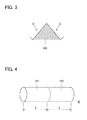
- FIG. 3 is an enlarged cross sectional view of FIG. 2 .
- FIG. 4 is a perspective view of a work (workpiece) W.
- the work W is a steel part to be used as machine parts.
- the work W shown in FIG. 4 is designed as a shaft having a simple shape. Such work W is put in a vacuum furnace and subjected to a carburizing treatment, thereby increasing a carbon content in the surface of the work W to improve abrasion resistance.
- the work W is a cylindrical shaft as shown in FIG. 4 , including a first work surface 101 and a second work surface 102.
- the work W is shown in a simple shape for convenience of explanation, but may take any other complicated shapes.
- the cross section of the work W is shown in enlarged form in FIGs. 1 and 2 , in which the first work surface 101 is made rougher in surface roughness than the second work surface 102.
- the first work surface 101 is a non-carburizing portion and the second work surface 102 is a carburizing portion that has to be subjected later to a carburizing treatment.
- the surface roughness in the first embodiment is set so that the first work surface 101 1 is Rz (Ten-point mean roughness) 50 and the second work surface 102 is Rz 1.5.
- the first work surface 101 is a surface processed to such a degree as obtained by machining such as lathing and pressing.
- the second work surface 102 is formed by grinding.
- the first work surface 101 has Rz (Ten-point mean roughness) 52.0 ⁇ m and Ra (Center line mean roughness) 12.6 ⁇ m (a measurement length is 12.5 mm).
- the second work surface 102 has Rz 1.4 ⁇ m and Ra 0.16 ⁇ m (a measurement length is 3.2 mm).
- FIG. 5 is a diagram showing a carburizing treatment.
- a vertical axis represents the temperature and a horizontal axis represents the time.
- the carburizing treatment is conducted by a "temperature increasing step”, a “carburizing and diffusing step", and an "N 2 cooling step”.
- the work W is put in a furnace.
- the furnace is evacuated to form a vacuum therein and the work W is heated.
- acetylene (C 2 H 2 ) gas to be used as carburizing gas C is filled in the furnace so that the surface of the work W is exposed to the carburizing gas C, thereby causing carbon to penetrate into the work W.
- the carburizing treatment using acetylene gas is known to be effective as a method of shortening a treating time as disclosed in for example JP 2008-223060A and others.
- the "N 2 cooling step” is a step of spraying nitrogen onto the work W to cool the work W. The use of nitrogen enables gas quench, thereby accelerating the cooling of the work W. Through the above process, the carburized work W is obtained.
- FIG. 6 is a graph showing carburizing depths in the work W.
- a vertical axis represents the carbon concentration and a horizontal axis represents the distance from the surface of the work W.
- a first carbon concentration curve L11 is an imaginary line showing a state of the first work surface 101 just after the start of the carburizing treatment to the work W.
- a second carbon concentration curve L2 is an imaginary line showing a state of the second work surface 102 just after the start of the carburizing treatment to the work W.
- a first after-cooling concentration curve L12 shows a result of measurement of concentration of the first work surface 101 after the work W passes through the "N 2 cooling step" of the carburizing treatment.
- a second after-cooling concentration curve L22 shows a measurement result of the carbon concentration of the second work surface 102 after the work W undergoes the "N 2 cooling step" of the carburizing treatment.
- the carbon concentration is measured by EPMA analysis.
- the first work surface 101 and the second carburizing 102 are different in carbon content as shown in FIG. 6 .
- the first carbon concentration curve L11 and the second carbon concentration curve L21 are almost equal in carbon concentration on the surfaces. However, as the distance from the surface is longer, the carbon concentration of the first carbon concentration curve L11 is lower at a faster rate than that of the second carbon concentration curve L21. The carbon concentration does not fall below a constant value because a base material itself of the work W contains carbon.
- the first after-cooling concentration curve L12 is lower in the carbon concentration itself on the surface than the second after-cooling concentration curve L22. It is also found that the first after-cooling concentration curve L12 is also lower in the total carbon content itself than the second after-cooling concentration curve L22.
- the carburized part manufacturing method in the first embodiment configured as above can provide the operations and advantages described below.
- a first advantage is to restrain carburizing in the non-carburizing portion at low cost.
- a portion desired to be the non-carburizing portion is made with a surface roughness of Rz 50 or more like the first work surface 101 and a portion desired to be the carburizing portion is made with a surface roughness corresponding to Rz 1.5 like the second work surface 102. Accordingly, the carburizing depth can be shallower in the first work surface 101 than in the second work surface 102 as shown in FIGs. 5 and 6 .
- the carbide is generated in the surface portion of the first work surface 101 by excess carburizing, so that carburizing reaction rapidly decreases.
- carbon is concentrated in protrusions of the first work surface 101 as shown in FIG. 3 , causing excess carburizing in the protrusions and hence forming carbide.
- the carbide is formed in the surface, the carbon is prevented from diffusing into the base material.
- a portion far from the surface of the first work surface 101 can be placed in an environment in which carburizing is unlikely to occur. It is therefore possible to make the work W easy to treat after the carburizing treatment and further prevent the occurrence of cracks during welding.
- the surface roughness of the non-carburizing portion is made rough like the first work surface 101, it is possible to restrain the carburizing. With such configuration, unlike the method of forming a coat in advance to form the non-carburizing portion, it is unnecessary to form the coat before the carburizing treatment and remove the coat after the carburizing treatment. Consequently, the working process can be shortened.
- the second embodiment is substantially the same in structure as the first embodiment, excepting a non-carburizing portion. This different configuration is explained below.
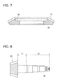
- FIG. 7 shows the shape of a work in the second embodiment.
- the work in the second embodiment is a bevel gear 20 including teeth 21 and an inner-circumferential annular portion ("annular portion") 22.
- the teeth 21 are subjected to the carburizing treatment, while the annular portion 22 is connected to a part or component not shown by welding. Accordingly, the teeth 21 are formed with the surface roughness equivalent to Rz 1.5 and the annular portion 22 is formed with the surface roughness equivalent to Rz 50.
- the bevel gear 20 in this state is put in a carburizing furnace not shown for conducting the carburizing treatment.
- the second embodiment configured as above can provide the operations and advantages described below.
- the teeth 21 needing higher abrasion resistance is a carburizing portion and the annular portion 22 to be subjected to welding is a non-carburizing portion.
- This configuration is similarly necessary for a spur gear and other gears.
- the teeth need the abrasion resistance, while the inner circumferential portion is preferred to have a lesser carbon content in internal structure in order to prevent the occurrence of cracks during welding.
- the third embodiment is substantially the same in structure as the first embodiment, excepting a non-carburizing portion. This different point is explained below.
- FIG. 8 shows the shape of a work in the third embodiment.
- the work in the third embodiment is a shaft 30 with a bevel gear, including a first stepped shaft portion 31, a second stepped shaft portion 32, and a gear portion 33.
- the first shaft portion 31 is a portion to be machined after carburizing and has a surface roughness of Rz 50 before carburizing.
- the second shaft portion 32 is a portion not to be machined after carburizing and has a surface roughness of Rz 1.5.
- the gear portion 33 is also to be subjected to the carburizing work and has a surface roughness of Rz 1.5.
- the carbon content in the material of a work increases, hardening a work surface. This deteriorates machinability of the work.
- the surface roughness of the first shaft portion 31 to be subjected to machining after the carburizing treatment is set to Rz 50, a carburized portion is in only a shallow superficial layer as shown in FIGs. 2 and 6 . This prevents the base material of the first shaft portion 31 from containing carbon and thus avoids deterioration of machinability thereof.
- the first shaft portion 31 is machined after the carburizing, leading to shortening of the working process of the shaft 30.
- the first shaft portion 31 needs no carburizing treatment but requires machining accuracy.
- the carburizing treatment may cause deformation or distortion of the material, thus resulting in deterioration in machining accuracy. Therefore, cutting and grinding have to be performed again after the carburizing treatment.
- the carburizing depth can be made shallow.
- omission of a treatment before the carburizing treatment can improve machinability after the carburizing treatment.
- the working process can be shortened. Consequently, the processing cost of the shaft 30 can be reduced.
- the present invention can be applied to any shapes of works other than the works shown in the first to third embodiments.
- the work surface roughness may be any surface roughness defined not only by the ten-point mean roughness but also by other evaluation methods.
- the surface roughness may also be set to be lower than Rz 1.5 to provide a smooth surface.
Landscapes
- Chemical & Material Sciences (AREA)
- Chemical Kinetics & Catalysis (AREA)
- Engineering & Computer Science (AREA)
- Materials Engineering (AREA)
- Mechanical Engineering (AREA)
- Metallurgy (AREA)
- Organic Chemistry (AREA)
- Solid-Phase Diffusion Into Metallic Material Surfaces (AREA)
- Heat Treatment Of Articles (AREA)
- Gears, Cams (AREA)
Abstract
Description
- The present invention relates to a technique of manufacturing a carburized part by providing different surface roughnesses for different portions of the carburized part to prevent carburizing thereof.
- A steel part or component constituting machinery includes many friction portions and thus is demanded in many cases to have abrasion resistance. A technique of carburizing the surface of a steel part or component to improve abrasion resistance is also used for parts or components constituting a vehicle. Actually, the parts subjected to the carburizing treatment are used throughout a vehicle.
- Carburizing an entire part can enhance the surface hardness of the part but may cause problems in which machining is difficult, breakages or cracks are apt to occur during welding, and others. Therefore, there is a demand to partially carburize only a desired portion. Various studies have accordingly been made to obtain a part in which a non-carburizing portion needing no carburizing is not carburized.
-
Patent Document 1 discloses a technique of suppressing and preventing carburizing and metal dusting. The surface of a metal member to be exposed to high-temperature carbon gas is plastic-deformed or plastic-strained in advance. This can control a carburizing depth in the carburizing treatment. This makes it possible to restrain a phenomenon in which metals and alloys disintegrate or decompose into dust in a carburizing atmosphere called metal dusting and the dust is blown off by a gas flow or the like, forming pits or causing abrasion wastage. -
Patent Document 2 discloses a technique of preventing carburizing of a welded portion. Considering circumstances that carburizing occurs in a welded joint, a first layer is welded to a base material and then a silicon-containing material is coated or stacked to a back side of the base material. This is reacted or fused (melted) by use of welding heat for second and subsequent layers, thus forming an oxide coat made of silica dioxide. This method can form the oxide coat, thereby preventing carburizing of the welded portion. - Patent Document 3 discloses a technique of a carburizing inhibiting material. A copper alloy coat is formed in a portion in which a screw part is to be formed. Thereby, the carburizing of the relevant portion is prevented during subsequent carburizing of a part.
- Patent Document 4 discloses a technique of preventing carburizing in a carburizing treatment. A tin coat is formed as a mask member on a portion desired to avoid carburizing, thereby preventing carburizing of the relevant portion.
- Patent Document 5 discloses a technique of preventing carburizing. On a portion desired to avoid carburizing, two or more kinds of carburizing inhibiting agents containing a first substance and a second substance is applied. The first substance is a substance, such as boric acid and boron oxide, that can be sequentially melted in a temperature range from a first temperature to a treating temperature, thereby sequentially coating the metal surface. The second substance is a substance, such as a mixture of rubber and an adhesive material, that can be melted in a temperature range from a normal temperature to at least the first temperature, thereby coating the metal surface. By such application of the carburizing preventing agent during a carburizing treatment, it is possible to prevent the carburizing treatment.
-
- Patent Document 1:
JP 11(1999)-269540 A - Patent Document 2:
JP 61(1986)-186166 A - Patent Document 3:
JP 2007-302969 A - Patent Document 4:
JP 11(1999)-302821 A - Patent Document 5:
JP 2000-096132 A - However,
Patent Documents 1 to 5 may cause the problems explained below. - In recent years, there is an increasing demand for cost reduction in vehicles. For even parts needing a carburizing treatment, a manufacturing method thereof is demanded to be reconsidered for reduction in cost. However, the methods disclosed in
Patent Documents 2 to 5, in which the coats are formed in advance in the non-carburizing portions prior to the carburizing treatment require an additional process of removing the coats after the carburizing treatment. As the number of working process steps increases, the part costs will increase. - The method disclosed in
Patent Document 1 also likely needs a plastic deformation process or a plastic-strain applying process to the non-carburizing portion before the carburizing treatment. This needs a processing cost. In many cases, portions to be formed as non-carburizing portions are considered to need no particular mechanical accuracy. In such case, the plastic-deformation process or the plastic-strain applying process has to be conducted only for preventing the carburizing treatment. Accordingly, cost will be increased. - The applicant has studied improvement of the carburizing treatment method to shorten the time required for the carburizing treatment. However, the conventional methods shown in
Patent Documents 1 to 5 needing an increase in working process step to restrain the carburizing portion could shorten the time required for the carburizing treatment but need a long lead time for making the non-carburizing portions. This brings an undesirable result that increases costs. - The present invention has been made to solve the above problems and has a purpose to provide a method of manufacturing a carburized part which can contribute to cost reduction.
- To achieve the above purpose, one aspect of the invention provides the following configurations.
- (1) A method of manufacturing a carburized part by carburizing a metal part including a carburizing portion to be carburized and a non-carburizing portion in which carburizing is to be restrained is characterized in that a work surface of a portion to be formed as the non-carburizing portion is made rougher in surface roughness than a work surface of a portion to be formed as the carburizing portion.
- (2) In the method of manufacturing the carburized part described in (1), preferably, the surface roughness of the work surface of the non-carburizing portion is set to at least Rz 50 or more.
- (3) In the method of manufacturing the carburized part described in (2), preferably, the portion to be formed as the non-carburizing portion is a portion to be welded after the carburizing treatment.
- (4) In the method of manufacturing the carburized part described in (1) or (2), preferably, the non-carburizing portion is a portion to be machined after the carburizing treatment.
- The method of manufacturing the carburized part according to one aspect of the invention configured as above can provide the following operations and advantages.
- The aspect of the invention described in (1) is a method of manufacturing a carburized part by carburizing a metal part including a carburizing portion to be carburized and a non-carburizing portion in which carburizing is to be restrained, wherein a work surface of a portion to be formed as the non-carburizing portion is made rougher in surface roughness than a work surface of a portion to be formed as the carburizing portion.
- Since the work surface roughness of the portion to be formed as the non-carburizing portion is made rougher, excess carburizing is likely caused in the non-carburizing portion by the edge effect and carbide is apt to occur in the surface of the non-carburizing portion. Thus, after the carbide is formed, further carburizing is prevented in the non-carburizing portion.
- As a result, a portion of the non-carburizing portion far from the surface can be placed in an environment in which carburizing less occurs. It is therefore possible to make the carburized part easy to machine after the carburizing treatment or prevent the occurrence of cracks during welding. Consequently, the surface treatments as disclosed in
Patent Documents 1 to 5 are not needed and thus the working process can be shortened. - According to the aspect of the invention described in (2), in the carburized part manufacturing method in (1), the surface roughness of the work surface of the non-carburizing portion is set to at least Rz 50 or more.
From the findings by the applicant, the edge effect disclose in (1) can be estimated when the non-carburizing portion is formed with the surface roughness of about Rz 50. If the surface roughness is about Rz 50, it is possible to restrain carburizing in the non-carburizing portion by an easy method. - According to the aspect of the invention described in (3), in the carburized part manufacturing method in (1) or (2), the portion to be formed as the non-carburizing portion is a portion to be welded after the carburizing treatment. Since the welded portion is formed as the non-carburizing portion, it is possible to prevent the occurrence of weld cracks and improve the weldability. When a portion intended to be welded is carburized and the content of carbon increases in a base material, the ductibility of the base material is apt to lower, leading to the occurrence of weld cracks during welding. In contrast, since the non-carburizing portion is formed with about Rz 50, carburizing of a portion to be welded later can be prevented and thus weld cracks can be avoided. Further, the rough surface roughness leads to improvement of weldability.
- According to the aspect of the invention described in (4), in the carburized part manufacturing method in (1) or (2), the non-carburizing portion is a portion to be machined after the carburizing treatment.
Since the portion to be machined after the carburizing treatment is formed as the non-carburizing portion, the carburizing of the non-carburizing portion can be restrained to maintain machinability. Increasing of carbon in a base material causes deterioration of machinability. It is therefore undesirable to carburize the portion to be machined later. In contrast, the portion to be machined later is formed as the non-carburizing portion, so that machinability can be maintained. -
-
FIG. 1 is a cross sectional view showing a state before a carburizing treatment in a first embodiment; -
FIG. 2 is a cross sectional view showing a state after the carburizing treatment in the first embodiment; -
FIG. 3 is an enlarged view showing the state after the carburizing treatment in the first embodiment; -
FIG. 4 is a perspective view of a work in the first embodiment; -
FIG. 5 is a diagram showing a process of the carburizing treatment in the first embodiment; -
FIG. 6 is a graph showing carburizing depths in a work in the first embodiment; -
FIG. 7 is a cross sectional view of a bevel gear which is a work in a second embodiment; and -
FIG. 8 is a partial cross sectional view of a shaft which is a work in a third embodiment. - A detailed description of a first preferred embodiment of the present invention will now be given referring to the accompanying drawings.
FIG. 1 is a cross sectional view showing a state of a work before a carburizing treatment in the first embodiment.FIG. 2 is a cross sectional view showing a state of the work before the carburizing treatment.FIG. 3 is an enlarged cross sectional view ofFIG. 2 .FIG. 4 is a perspective view of a work (workpiece) W. - The work W is a steel part to be used as machine parts. The work W shown in
FIG. 4 is designed as a shaft having a simple shape. Such work W is put in a vacuum furnace and subjected to a carburizing treatment, thereby increasing a carbon content in the surface of the work W to improve abrasion resistance. The work W is a cylindrical shaft as shown inFIG. 4 , including afirst work surface 101 and asecond work surface 102. The work W is shown in a simple shape for convenience of explanation, but may take any other complicated shapes. - The cross section of the work W is shown in enlarged form in
FIGs. 1 and 2 , in which thefirst work surface 101 is made rougher in surface roughness than thesecond work surface 102. Thefirst work surface 101 is a non-carburizing portion and thesecond work surface 102 is a carburizing portion that has to be subjected later to a carburizing treatment. The surface roughness in the first embodiment is set so that thefirst work surface 101 1 is Rz (Ten-point mean roughness) 50 and thesecond work surface 102 is Rz 1.5. Thefirst work surface 101 is a surface processed to such a degree as obtained by machining such as lathing and pressing. Thesecond work surface 102 is formed by grinding. - In actual measurements, the
first work surface 101 has Rz (Ten-point mean roughness) 52.0 µm and Ra (Center line mean roughness) 12.6 µm (a measurement length is 12.5 mm). Thesecond work surface 102 has Rz 1.4 µm and Ra 0.16 µm (a measurement length is 3.2 mm). -
FIG. 5 is a diagram showing a carburizing treatment. A vertical axis represents the temperature and a horizontal axis represents the time. For carburizing the work W, the carburizing treatment is conducted by a "temperature increasing step", a "carburizing and diffusing step", and an "N2 cooling step". - In the "temperature increasing step", the work W is put in a furnace. The furnace is evacuated to form a vacuum therein and the work W is heated. In the "carburizing and diffusing step", acetylene (C2H2) gas to be used as carburizing gas C is filled in the furnace so that the surface of the work W is exposed to the carburizing gas C, thereby causing carbon to penetrate into the work W. The carburizing treatment using acetylene gas is known to be effective as a method of shortening a treating time as disclosed in for example
JP 2008-223060A -
FIG. 6 is a graph showing carburizing depths in the work W. A vertical axis represents the carbon concentration and a horizontal axis represents the distance from the surface of the work W. - A first carbon concentration curve L11 is an imaginary line showing a state of the
first work surface 101 just after the start of the carburizing treatment to the work W. A second carbon concentration curve L2 is an imaginary line showing a state of thesecond work surface 102 just after the start of the carburizing treatment to the work W. A first after-cooling concentration curve L12 shows a result of measurement of concentration of thefirst work surface 101 after the work W passes through the "N2 cooling step" of the carburizing treatment. - A second after-cooling concentration curve L22 shows a measurement result of the carbon concentration of the
second work surface 102 after the work W undergoes the "N2 cooling step" of the carburizing treatment. The carbon concentration is measured by EPMA analysis. In the case where the work W is subjected to the carburizing treatment, thefirst work surface 101 and thesecond carburizing 102 are different in carbon content as shown inFIG. 6 . - Specifically, the first carbon concentration curve L11 and the second carbon concentration curve L21 are almost equal in carbon concentration on the surfaces. However, as the distance from the surface is longer, the carbon concentration of the first carbon concentration curve L11 is lower at a faster rate than that of the second carbon concentration curve L21. The carbon concentration does not fall below a constant value because a base material itself of the work W contains carbon.
- Comparing between the first after-cooling concentration curve L12 and the second after-cooling concentration curve L22, the first after-cooling concentration curve L12 is lower in the carbon concentration itself on the surface than the second after-cooling concentration curve L22. It is also found that the first after-cooling concentration curve L12 is also lower in the total carbon content itself than the second after-cooling concentration curve L22.
- Changing from the first carbon concentration curve L11 to the first after-cooling concentration curve L12 and changing from the second carbon concentration curve L21 to the second after-cooling concentration curve L22 are caused by diffusion of carbon into the work W.
- The carburized part manufacturing method in the first embodiment configured as above can provide the operations and advantages described below.
- A first advantage is to restrain carburizing in the non-carburizing portion at low cost.
- Specifically, a portion desired to be the non-carburizing portion is made with a surface roughness of Rz 50 or more like the
first work surface 101 and a portion desired to be the carburizing portion is made with a surface roughness corresponding to Rz 1.5 like thesecond work surface 102. Accordingly, the carburizing depth can be shallower in thefirst work surface 101 than in thesecond work surface 102 as shown inFIGs. 5 and 6 . - Consequently, the surface area of the
first work surface 101 exposed to the carburizing gas C becomes wider as shown inFIG. 3 . This configuration likely causes excess carburizing due to an edge effect and hence carbide (cementite structure) is easy to generate on the surface. This tendency more prominently appears as shortening of the carburizing time is advanced. - Accordingly, the carbide is generated in the surface portion of the
first work surface 101 by excess carburizing, so that carburizing reaction rapidly decreases. To be concrete, carbon is concentrated in protrusions of thefirst work surface 101 as shown inFIG. 3 , causing excess carburizing in the protrusions and hence forming carbide. When the carbide is formed in the surface, the carbon is prevented from diffusing into the base material. As a result, a portion far from the surface of thefirst work surface 101 can be placed in an environment in which carburizing is unlikely to occur. It is therefore possible to make the work W easy to treat after the carburizing treatment and further prevent the occurrence of cracks during welding. - Since the cementite structure is a brittle and hard structure and thus the tenacity or toughness lowers, a normal carburizing treatment is conducted without actively precipitating carbide. However, according to the present invention, carbide is generated at an earlier stage of the "carburizing and diffusing step", so that carburizing in a portion far from the surface can be prevented.
- Since the surface roughness of the non-carburizing portion is made rough like the
first work surface 101, it is possible to restrain the carburizing. With such configuration, unlike the method of forming a coat in advance to form the non-carburizing portion, it is unnecessary to form the coat before the carburizing treatment and remove the coat after the carburizing treatment. Consequently, the working process can be shortened. - A second embodiment of the present invention will be explained below.
- The second embodiment is substantially the same in structure as the first embodiment, excepting a non-carburizing portion. This different configuration is explained below.
-
FIG. 7 shows the shape of a work in the second embodiment. The work in the second embodiment is abevel gear 20 includingteeth 21 and an inner-circumferential annular portion ("annular portion") 22. Theteeth 21 are subjected to the carburizing treatment, while theannular portion 22 is connected to a part or component not shown by welding. Accordingly, theteeth 21 are formed with the surface roughness equivalent to Rz 1.5 and theannular portion 22 is formed with the surface roughness equivalent to Rz 50. Thebevel gear 20 in this state is put in a carburizing furnace not shown for conducting the carburizing treatment. - The second embodiment configured as above can provide the operations and advantages described below.
- In the gear, it is desired that the
teeth 21 needing higher abrasion resistance is a carburizing portion and theannular portion 22 to be subjected to welding is a non-carburizing portion. This configuration is similarly necessary for a spur gear and other gears. Specifically, the teeth need the abrasion resistance, while the inner circumferential portion is preferred to have a lesser carbon content in internal structure in order to prevent the occurrence of cracks during welding. - When a welded portion is clamped by the surroundings during welding, weld cracks are generated when it exceeds ductibility of a welding-heat affected zone due to heat distortion resulting from welding. When a carburized layer is formed by the carburizing treatment, ductibility lowers and hence weld cracks are likely to occur due to welding. However, when the
annular portion 22 is made to have a surface roughness of Rz 50, carburizing of theannular portion 22 can be prevented during the carburizing treatment. This can prevent the occurrence of weld cracks. Further, since theannular portion 22 is designed to be rough with the surface roughness of about Rz 50, it also can contribute to improvement of weldability. - A third embodiment of the invention will be explained below.
- The third embodiment is substantially the same in structure as the first embodiment, excepting a non-carburizing portion. This different point is explained below.
-
FIG. 8 shows the shape of a work in the third embodiment. The work in the third embodiment is ashaft 30 with a bevel gear, including a first steppedshaft portion 31, a second steppedshaft portion 32, and agear portion 33. - The
first shaft portion 31 is a portion to be machined after carburizing and has a surface roughness of Rz 50 before carburizing. Thesecond shaft portion 32 is a portion not to be machined after carburizing and has a surface roughness of Rz 1.5. Thegear portion 33 is also to be subjected to the carburizing work and has a surface roughness of Rz 1.5. - After the carburizing treatment, the carbon content in the material of a work increases, hardening a work surface. This deteriorates machinability of the work. However, since the surface roughness of the
first shaft portion 31 to be subjected to machining after the carburizing treatment is set to Rz 50, a carburized portion is in only a shallow superficial layer as shown inFIGs. 2 and6 . This prevents the base material of thefirst shaft portion 31 from containing carbon and thus avoids deterioration of machinability thereof. - Then, the
first shaft portion 31 is machined after the carburizing, leading to shortening of the working process of theshaft 30. Thefirst shaft portion 31 needs no carburizing treatment but requires machining accuracy. In this case, the carburizing treatment may cause deformation or distortion of the material, thus resulting in deterioration in machining accuracy. Therefore, cutting and grinding have to be performed again after the carburizing treatment. - However, since the
first shaft portion 31 made rough with the surface roughness of about Rz 50 is subjected to the carburizing treatment, the carburizing depth can be made shallow. As a result, omission of a treatment before the carburizing treatment can improve machinability after the carburizing treatment. In other words, the working process can be shortened. Consequently, the processing cost of theshaft 30 can be reduced. - The invention is not limited to the above embodiments but may be embodied in other specific forms without departing from the essential characteristics thereof.
- For instance, the present invention can be applied to any shapes of works other than the works shown in the first to third embodiments. Further, the work surface roughness may be any surface roughness defined not only by the ten-point mean roughness but also by other evaluation methods. The surface roughness may also be set to be lower than Rz 1.5 to provide a smooth surface.
-
DESCRIPTION OF THE REFERENCE SIGNS 21 Teeth 22 Inner circumferential annular portion 30 Shaft 31 First stepped shaft portion 32 Second stepped shaft portion 33 Gear portion 101 First work surface 102 Second work surface C Carburizing gas L11 First carbon concentration curve L12 First after-cooling concentration curve L21 Second carbon concentration curve L22 Second after-cooling concentration curve W Workpiece
Claims (4)
- A method of manufacturing a carburized part by carburizing a metal part including a carburizing portion to be carburized and a non-carburizing portion in which carburizing is to be restrained,
wherein a work surface of a portion to be formed as the non-carburizing portion is made rougher in surface roughness than a work surface of a portion to be formed as the carburizing portion. - The method of manufacturing a carburized part according to claim 1, wherein the surface roughness of the work surface of the non-carburizing portion is set to at least Rz 50 or more.
- The method of manufacturing a carburized part according to claim 1 or 2, wherein the portion to be formed as the non-carburizing portion is a portion to be welded after the carburizing treatment.
- The method of manufacturing a carburized part according to claim 1 or 2, wherein the non-carburizing portion is a portion to be machined after the carburizing treatment.
Applications Claiming Priority (1)
| Application Number | Priority Date | Filing Date | Title |
|---|---|---|---|
| PCT/JP2010/065544 WO2012032637A1 (en) | 2010-09-09 | 2010-09-09 | Process for producing carburized part |
Publications (3)
| Publication Number | Publication Date |
|---|---|
| EP2615192A1 true EP2615192A1 (en) | 2013-07-17 |
| EP2615192A4 EP2615192A4 (en) | 2014-09-03 |
| EP2615192B1 EP2615192B1 (en) | 2017-05-03 |
Family
ID=44693621
Family Applications (1)
| Application Number | Title | Priority Date | Filing Date |
|---|---|---|---|
| EP10846303.5A Not-in-force EP2615192B1 (en) | 2010-09-09 | 2010-09-09 | Method of manufacturing carburized parts |
Country Status (6)
| Country | Link |
|---|---|
| US (1) | US8172957B2 (en) |
| EP (1) | EP2615192B1 (en) |
| JP (1) | JP4771025B1 (en) |
| KR (1) | KR101167818B1 (en) |
| CN (1) | CN102523745B (en) |
| WO (1) | WO2012032637A1 (en) |
Families Citing this family (6)
| Publication number | Priority date | Publication date | Assignee | Title |
|---|---|---|---|---|
| JP5754608B2 (en) * | 2012-03-05 | 2015-07-29 | トヨタ自動車株式会社 | Manufacturing method of machined parts and machined parts |
| JP6069067B2 (en) * | 2013-03-27 | 2017-01-25 | アイシン・エィ・ダブリュ株式会社 | Manufacturing method of composite parts |
| US10174395B2 (en) * | 2015-10-15 | 2019-01-08 | The Boeing Company | Interference fit quench plug assembly and methods for use thereof |
| KR20180080843A (en) * | 2017-01-05 | 2018-07-13 | 현대자동차주식회사 | Alloy steel which carburizing is prevented by processing load and the method of manufacturing thereof |
| CN108284877A (en) * | 2017-12-18 | 2018-07-17 | 合肥亿恒智能科技股份有限公司 | A kind of automobile longitudinal girder and skirtboard connector and preparation method thereof |
| CN110408882B (en) * | 2019-08-26 | 2021-10-01 | 山东亨格尔智能科技有限公司 | Anti-carburizing treatment method |
Family Cites Families (15)
| Publication number | Priority date | Publication date | Assignee | Title |
|---|---|---|---|---|
| US4303137A (en) * | 1979-09-21 | 1981-12-01 | Smith International, Inc. | Method for making a cone for a rock bit and product |
| JPS61186166A (en) | 1985-02-13 | 1986-08-19 | Babcock Hitachi Kk | Prevention of carburization of weld zone |
| US4798077A (en) * | 1987-02-12 | 1989-01-17 | Eaton Corporation | Method for producing a family of forged ring rolling preforms and forging die therefor |
| CN1032263C (en) * | 1992-01-06 | 1996-07-10 | 大同酸素株式会社 | Motor rotary shaft and manufacturing method thereof |
| JPH0873929A (en) * | 1994-08-31 | 1996-03-19 | Komatsu Ltd | Machine element parts and manufacturing method thereof |
| SE508467C2 (en) * | 1995-03-13 | 1998-10-12 | Sandvik Ab | Rock drill bit for rotating crushing machining of rock and ways to harden such rock drill bit |
| JPH09302454A (en) * | 1996-05-13 | 1997-11-25 | Toyota Central Res & Dev Lab Inc | Pretreatment method for carburized and quenched material and manufacturing method for carburized and quenched material |
| JP2876206B1 (en) * | 1998-03-18 | 1999-03-31 | 川崎重工業株式会社 | How to control and prevent carburization and metal dusting |
| WO1999047810A1 (en) * | 1998-03-19 | 1999-09-23 | Sumitomo Electric Industries, Ltd. | Combination of shim and cam |
| JP3314030B2 (en) | 1998-04-22 | 2002-08-12 | 株式会社不二機販 | Carburizing prevention method in carburizing treatment |
| JP2000074324A (en) * | 1998-08-28 | 2000-03-14 | Osaka Gas Co Ltd | Carburizing preventive surface working |
| JP2000096132A (en) | 1998-09-28 | 2000-04-04 | Hitoshi Komori | Carburization inhibiting method, carburization inhibitor and member to be heat-treated |
| JP2000220627A (en) * | 1999-01-28 | 2000-08-08 | Honda Motor Co Ltd | Method of manufacturing connecting rod for internal combustion engine |
| JP2004244673A (en) * | 2003-02-13 | 2004-09-02 | Nissan Motor Co Ltd | Carburizing method |
| JP2007302969A (en) | 2006-05-12 | 2007-11-22 | Toyota Motor Corp | Carburization inhibitor |
-
2010
- 2010-09-09 CN CN201080019451XA patent/CN102523745B/en not_active Expired - Fee Related
- 2010-09-09 US US13/203,587 patent/US8172957B2/en not_active Expired - Fee Related
- 2010-09-09 WO PCT/JP2010/065544 patent/WO2012032637A1/en not_active Ceased
- 2010-09-09 KR KR1020117025613A patent/KR101167818B1/en not_active Expired - Fee Related
- 2010-09-09 JP JP2011506516A patent/JP4771025B1/en not_active Expired - Fee Related
- 2010-09-09 EP EP10846303.5A patent/EP2615192B1/en not_active Not-in-force
Also Published As
| Publication number | Publication date |
|---|---|
| US8172957B2 (en) | 2012-05-08 |
| KR20120041159A (en) | 2012-04-30 |
| EP2615192A4 (en) | 2014-09-03 |
| EP2615192B1 (en) | 2017-05-03 |
| US20120060977A1 (en) | 2012-03-15 |
| WO2012032637A1 (en) | 2012-03-15 |
| KR101167818B1 (en) | 2012-07-26 |
| JP4771025B1 (en) | 2011-09-14 |
| JPWO2012032637A1 (en) | 2013-12-12 |
| CN102523745A (en) | 2012-06-27 |
| CN102523745B (en) | 2013-12-04 |
Similar Documents
| Publication | Publication Date | Title |
|---|---|---|
| EP2615192B1 (en) | Method of manufacturing carburized parts | |
| EP3118346B1 (en) | Nitriding method and nitrided part production method | |
| JP5299140B2 (en) | MATERIAL OF SHOT PEENING PROJECTION MATERIAL AND METHOD FOR PRODUCING SHOT PEENING PROJECTION MATERIAL | |
| JP2021504570A (en) | A method of preparing a filler wire having a specified carbon content to manufacture a welded steel blank, a method of manufacturing a welded part using a related welded blank, a hot press formed and cooled steel part, and a related part. | |
| CN1829816A (en) | Method for manufacturing hardened parts from sheet steel | |
| EP2133435A1 (en) | Jig for vacuum heat treatment and method of vacuum heat treatment | |
| KR20150067358A (en) | Bearing element, rolling bearing and process for producing bearing element | |
| JP6314648B2 (en) | Surface hardened component and method for manufacturing surface hardened component | |
| JPWO2017043594A1 (en) | Nitrided steel parts and manufacturing method thereof | |
| JP2015151562A (en) | Local surface reinforcing member and local surface reinforcing method | |
| JP2010222648A (en) | Carbon steel material manufacturing method and carbon steel material | |
| EP1291445B1 (en) | Steel material production method | |
| JPH08225851A (en) | Method for correcting quenching deformation of annular body | |
| JP7017489B2 (en) | Bearing parts | |
| KR102309003B1 (en) | Cementation heat treatment method for steel and manufactured steel by the same | |
| US20060266436A1 (en) | Carburizing method | |
| JP2016098426A (en) | Case-hardened steel with excellent pitting resistance used on carburized skin | |
| JP6543981B2 (en) | β-type titanium alloy sheet | |
| JP7684828B2 (en) | Carburized parts | |
| JPH0810826A (en) | Manufacturing method of alloy steel cold drawn wire rod for bearing | |
| JP4327812B2 (en) | Manufacturing method of carburized parts | |
| WO2023080064A1 (en) | Shaft member and rolling bearing | |
| JP2025007906A (en) | Shaft member for crimping and bearing device for planetary gear reducer | |
| EP4265366A1 (en) | Method for manufacturing tailor welded blank using steel sheet for hot pressing having al-fe-based intermetallic alloy layer | |
| JP2025025143A (en) | Bearing parts |
Legal Events
| Date | Code | Title | Description |
|---|---|---|---|
| PUAI | Public reference made under article 153(3) epc to a published international application that has entered the european phase |
Free format text: ORIGINAL CODE: 0009012 |
|
| 17P | Request for examination filed |
Effective date: 20110919 |
|
| AK | Designated contracting states |
Kind code of ref document: A1 Designated state(s): AL AT BE BG CH CY CZ DE DK EE ES FI FR GB GR HR HU IE IS IT LI LT LU LV MC MK MT NL NO PL PT RO SE SI SK SM TR |
|
| DAX | Request for extension of the european patent (deleted) | ||
| A4 | Supplementary search report drawn up and despatched |
Effective date: 20140805 |
|
| RIC1 | Information provided on ipc code assigned before grant |
Ipc: C23C 8/20 20060101ALI20140730BHEP Ipc: C23C 8/04 20060101ALI20140730BHEP Ipc: C23C 8/02 20060101AFI20140730BHEP |
|
| 17Q | First examination report despatched |
Effective date: 20150702 |
|
| GRAP | Despatch of communication of intention to grant a patent |
Free format text: ORIGINAL CODE: EPIDOSNIGR1 |
|
| STAA | Information on the status of an ep patent application or granted ep patent |
Free format text: STATUS: GRANT OF PATENT IS INTENDED |
|
| INTG | Intention to grant announced |
Effective date: 20161124 |
|
| GRAS | Grant fee paid |
Free format text: ORIGINAL CODE: EPIDOSNIGR3 |
|
| GRAA | (expected) grant |
Free format text: ORIGINAL CODE: 0009210 |
|
| STAA | Information on the status of an ep patent application or granted ep patent |
Free format text: STATUS: THE PATENT HAS BEEN GRANTED |
|
| AK | Designated contracting states |
Kind code of ref document: B1 Designated state(s): AL AT BE BG CH CY CZ DE DK EE ES FI FR GB GR HR HU IE IS IT LI LT LU LV MC MK MT NL NO PL PT RO SE SI SK SM TR |
|
| REG | Reference to a national code |
Ref country code: GB Ref legal event code: FG4D |
|
| REG | Reference to a national code |
Ref country code: AT Ref legal event code: REF Ref document number: 890074 Country of ref document: AT Kind code of ref document: T Effective date: 20170515 Ref country code: CH Ref legal event code: EP |
|
| REG | Reference to a national code |
Ref country code: IE Ref legal event code: FG4D |
|
| REG | Reference to a national code |
Ref country code: DE Ref legal event code: R096 Ref document number: 602010042133 Country of ref document: DE |
|
| REG | Reference to a national code |
Ref country code: DE Ref legal event code: R084 Ref document number: 602010042133 Country of ref document: DE |
|
| REG | Reference to a national code |
Ref country code: NL Ref legal event code: MP Effective date: 20170503 |
|
| REG | Reference to a national code |
Ref country code: AT Ref legal event code: MK05 Ref document number: 890074 Country of ref document: AT Kind code of ref document: T Effective date: 20170503 |
|
| REG | Reference to a national code |
Ref country code: LT Ref legal event code: MG4D |
|
| PG25 | Lapsed in a contracting state [announced via postgrant information from national office to epo] |
Ref country code: HR Free format text: LAPSE BECAUSE OF FAILURE TO SUBMIT A TRANSLATION OF THE DESCRIPTION OR TO PAY THE FEE WITHIN THE PRESCRIBED TIME-LIMIT Effective date: 20170503 Ref country code: AT Free format text: LAPSE BECAUSE OF FAILURE TO SUBMIT A TRANSLATION OF THE DESCRIPTION OR TO PAY THE FEE WITHIN THE PRESCRIBED TIME-LIMIT Effective date: 20170503 Ref country code: GR Free format text: LAPSE BECAUSE OF FAILURE TO SUBMIT A TRANSLATION OF THE DESCRIPTION OR TO PAY THE FEE WITHIN THE PRESCRIBED TIME-LIMIT Effective date: 20170804 Ref country code: LT Free format text: LAPSE BECAUSE OF FAILURE TO SUBMIT A TRANSLATION OF THE DESCRIPTION OR TO PAY THE FEE WITHIN THE PRESCRIBED TIME-LIMIT Effective date: 20170503 Ref country code: ES Free format text: LAPSE BECAUSE OF FAILURE TO SUBMIT A TRANSLATION OF THE DESCRIPTION OR TO PAY THE FEE WITHIN THE PRESCRIBED TIME-LIMIT Effective date: 20170503 Ref country code: NO Free format text: LAPSE BECAUSE OF FAILURE TO SUBMIT A TRANSLATION OF THE DESCRIPTION OR TO PAY THE FEE WITHIN THE PRESCRIBED TIME-LIMIT Effective date: 20170803 Ref country code: FI Free format text: LAPSE BECAUSE OF FAILURE TO SUBMIT A TRANSLATION OF THE DESCRIPTION OR TO PAY THE FEE WITHIN THE PRESCRIBED TIME-LIMIT Effective date: 20170503 |
|
| PG25 | Lapsed in a contracting state [announced via postgrant information from national office to epo] |
Ref country code: SE Free format text: LAPSE BECAUSE OF FAILURE TO SUBMIT A TRANSLATION OF THE DESCRIPTION OR TO PAY THE FEE WITHIN THE PRESCRIBED TIME-LIMIT Effective date: 20170503 Ref country code: LV Free format text: LAPSE BECAUSE OF FAILURE TO SUBMIT A TRANSLATION OF THE DESCRIPTION OR TO PAY THE FEE WITHIN THE PRESCRIBED TIME-LIMIT Effective date: 20170503 Ref country code: NL Free format text: LAPSE BECAUSE OF FAILURE TO SUBMIT A TRANSLATION OF THE DESCRIPTION OR TO PAY THE FEE WITHIN THE PRESCRIBED TIME-LIMIT Effective date: 20170503 Ref country code: PL Free format text: LAPSE BECAUSE OF FAILURE TO SUBMIT A TRANSLATION OF THE DESCRIPTION OR TO PAY THE FEE WITHIN THE PRESCRIBED TIME-LIMIT Effective date: 20170503 Ref country code: IS Free format text: LAPSE BECAUSE OF FAILURE TO SUBMIT A TRANSLATION OF THE DESCRIPTION OR TO PAY THE FEE WITHIN THE PRESCRIBED TIME-LIMIT Effective date: 20170903 Ref country code: BG Free format text: LAPSE BECAUSE OF FAILURE TO SUBMIT A TRANSLATION OF THE DESCRIPTION OR TO PAY THE FEE WITHIN THE PRESCRIBED TIME-LIMIT Effective date: 20170803 |
|
| PG25 | Lapsed in a contracting state [announced via postgrant information from national office to epo] |
Ref country code: DK Free format text: LAPSE BECAUSE OF FAILURE TO SUBMIT A TRANSLATION OF THE DESCRIPTION OR TO PAY THE FEE WITHIN THE PRESCRIBED TIME-LIMIT Effective date: 20170503 Ref country code: CZ Free format text: LAPSE BECAUSE OF FAILURE TO SUBMIT A TRANSLATION OF THE DESCRIPTION OR TO PAY THE FEE WITHIN THE PRESCRIBED TIME-LIMIT Effective date: 20170503 Ref country code: EE Free format text: LAPSE BECAUSE OF FAILURE TO SUBMIT A TRANSLATION OF THE DESCRIPTION OR TO PAY THE FEE WITHIN THE PRESCRIBED TIME-LIMIT Effective date: 20170503 Ref country code: RO Free format text: LAPSE BECAUSE OF FAILURE TO SUBMIT A TRANSLATION OF THE DESCRIPTION OR TO PAY THE FEE WITHIN THE PRESCRIBED TIME-LIMIT Effective date: 20170503 Ref country code: SK Free format text: LAPSE BECAUSE OF FAILURE TO SUBMIT A TRANSLATION OF THE DESCRIPTION OR TO PAY THE FEE WITHIN THE PRESCRIBED TIME-LIMIT Effective date: 20170503 |
|
| REG | Reference to a national code |
Ref country code: DE Ref legal event code: R097 Ref document number: 602010042133 Country of ref document: DE |
|
| PG25 | Lapsed in a contracting state [announced via postgrant information from national office to epo] |
Ref country code: IT Free format text: LAPSE BECAUSE OF FAILURE TO SUBMIT A TRANSLATION OF THE DESCRIPTION OR TO PAY THE FEE WITHIN THE PRESCRIBED TIME-LIMIT Effective date: 20170503 Ref country code: SM Free format text: LAPSE BECAUSE OF FAILURE TO SUBMIT A TRANSLATION OF THE DESCRIPTION OR TO PAY THE FEE WITHIN THE PRESCRIBED TIME-LIMIT Effective date: 20170503 |
|
| PLBE | No opposition filed within time limit |
Free format text: ORIGINAL CODE: 0009261 |
|
| STAA | Information on the status of an ep patent application or granted ep patent |
Free format text: STATUS: NO OPPOSITION FILED WITHIN TIME LIMIT |
|
| 26N | No opposition filed |
Effective date: 20180206 |
|
| REG | Reference to a national code |
Ref country code: CH Ref legal event code: PL |
|
| GBPC | Gb: european patent ceased through non-payment of renewal fee |
Effective date: 20170909 |
|
| PG25 | Lapsed in a contracting state [announced via postgrant information from national office to epo] |
Ref country code: MC Free format text: LAPSE BECAUSE OF FAILURE TO SUBMIT A TRANSLATION OF THE DESCRIPTION OR TO PAY THE FEE WITHIN THE PRESCRIBED TIME-LIMIT Effective date: 20170503 Ref country code: SI Free format text: LAPSE BECAUSE OF FAILURE TO SUBMIT A TRANSLATION OF THE DESCRIPTION OR TO PAY THE FEE WITHIN THE PRESCRIBED TIME-LIMIT Effective date: 20170503 |
|
| REG | Reference to a national code |
Ref country code: IE Ref legal event code: MM4A |
|
| REG | Reference to a national code |
Ref country code: BE Ref legal event code: MM Effective date: 20170930 |
|
| PG25 | Lapsed in a contracting state [announced via postgrant information from national office to epo] |
Ref country code: LU Free format text: LAPSE BECAUSE OF NON-PAYMENT OF DUE FEES Effective date: 20170909 |
|
| REG | Reference to a national code |
Ref country code: FR Ref legal event code: ST Effective date: 20180531 |
|
| PG25 | Lapsed in a contracting state [announced via postgrant information from national office to epo] |
Ref country code: IE Free format text: LAPSE BECAUSE OF NON-PAYMENT OF DUE FEES Effective date: 20170909 Ref country code: CH Free format text: LAPSE BECAUSE OF NON-PAYMENT OF DUE FEES Effective date: 20170930 Ref country code: LI Free format text: LAPSE BECAUSE OF NON-PAYMENT OF DUE FEES Effective date: 20170930 Ref country code: GB Free format text: LAPSE BECAUSE OF NON-PAYMENT OF DUE FEES Effective date: 20170909 |
|
| PG25 | Lapsed in a contracting state [announced via postgrant information from national office to epo] |
Ref country code: FR Free format text: LAPSE BECAUSE OF NON-PAYMENT OF DUE FEES Effective date: 20171002 Ref country code: BE Free format text: LAPSE BECAUSE OF NON-PAYMENT OF DUE FEES Effective date: 20170930 |
|
| PG25 | Lapsed in a contracting state [announced via postgrant information from national office to epo] |
Ref country code: MT Free format text: LAPSE BECAUSE OF NON-PAYMENT OF DUE FEES Effective date: 20170909 |
|
| PG25 | Lapsed in a contracting state [announced via postgrant information from national office to epo] |
Ref country code: HU Free format text: LAPSE BECAUSE OF FAILURE TO SUBMIT A TRANSLATION OF THE DESCRIPTION OR TO PAY THE FEE WITHIN THE PRESCRIBED TIME-LIMIT; INVALID AB INITIO Effective date: 20100909 |
|
| PG25 | Lapsed in a contracting state [announced via postgrant information from national office to epo] |
Ref country code: CY Free format text: LAPSE BECAUSE OF NON-PAYMENT OF DUE FEES Effective date: 20170503 |
|
| PG25 | Lapsed in a contracting state [announced via postgrant information from national office to epo] |
Ref country code: MK Free format text: LAPSE BECAUSE OF FAILURE TO SUBMIT A TRANSLATION OF THE DESCRIPTION OR TO PAY THE FEE WITHIN THE PRESCRIBED TIME-LIMIT Effective date: 20170503 |
|
| PG25 | Lapsed in a contracting state [announced via postgrant information from national office to epo] |
Ref country code: TR Free format text: LAPSE BECAUSE OF FAILURE TO SUBMIT A TRANSLATION OF THE DESCRIPTION OR TO PAY THE FEE WITHIN THE PRESCRIBED TIME-LIMIT Effective date: 20170503 |
|
| PG25 | Lapsed in a contracting state [announced via postgrant information from national office to epo] |
Ref country code: PT Free format text: LAPSE BECAUSE OF FAILURE TO SUBMIT A TRANSLATION OF THE DESCRIPTION OR TO PAY THE FEE WITHIN THE PRESCRIBED TIME-LIMIT Effective date: 20170503 |
|
| PG25 | Lapsed in a contracting state [announced via postgrant information from national office to epo] |
Ref country code: AL Free format text: LAPSE BECAUSE OF FAILURE TO SUBMIT A TRANSLATION OF THE DESCRIPTION OR TO PAY THE FEE WITHIN THE PRESCRIBED TIME-LIMIT Effective date: 20170503 |
|
| PGFP | Annual fee paid to national office [announced via postgrant information from national office to epo] |
Ref country code: DE Payment date: 20210727 Year of fee payment: 12 |
|
| REG | Reference to a national code |
Ref country code: DE Ref legal event code: R119 Ref document number: 602010042133 Country of ref document: DE |
|
| PG25 | Lapsed in a contracting state [announced via postgrant information from national office to epo] |
Ref country code: DE Free format text: LAPSE BECAUSE OF NON-PAYMENT OF DUE FEES Effective date: 20230401 |