EP2615031A1 - Speed sensor module and diffuser assembly - Google Patents
Speed sensor module and diffuser assembly Download PDFInfo
- Publication number
- EP2615031A1 EP2615031A1 EP13150802.0A EP13150802A EP2615031A1 EP 2615031 A1 EP2615031 A1 EP 2615031A1 EP 13150802 A EP13150802 A EP 13150802A EP 2615031 A1 EP2615031 A1 EP 2615031A1
- Authority
- EP
- European Patent Office
- Prior art keywords
- speed sensor
- sensor module
- bore
- air
- aligned
- Prior art date
- Legal status (The legal status is an assumption and is not a legal conclusion. Google has not performed a legal analysis and makes no representation as to the accuracy of the status listed.)
- Granted
Links
Images

Classifications
-
- B—PERFORMING OPERATIONS; TRANSPORTING
- B64—AIRCRAFT; AVIATION; COSMONAUTICS
- B64D—EQUIPMENT FOR FITTING IN OR TO AIRCRAFT; FLIGHT SUITS; PARACHUTES; ARRANGEMENT OR MOUNTING OF POWER PLANTS OR PROPULSION TRANSMISSIONS IN AIRCRAFT
- B64D13/00—Arrangements or adaptations of air-treatment apparatus for aircraft crew or passengers, or freight space
- B64D13/06—Arrangements or adaptations of air-treatment apparatus for aircraft crew or passengers, or freight space the air being conditioned
-
- F—MECHANICAL ENGINEERING; LIGHTING; HEATING; WEAPONS; BLASTING
- F01—MACHINES OR ENGINES IN GENERAL; ENGINE PLANTS IN GENERAL; STEAM ENGINES
- F01D—NON-POSITIVE DISPLACEMENT MACHINES OR ENGINES, e.g. STEAM TURBINES
- F01D17/00—Regulating or controlling by varying flow
- F01D17/02—Arrangement of sensing elements
- F01D17/06—Arrangement of sensing elements responsive to speed
-
- F—MECHANICAL ENGINEERING; LIGHTING; HEATING; WEAPONS; BLASTING
- F04—POSITIVE - DISPLACEMENT MACHINES FOR LIQUIDS; PUMPS FOR LIQUIDS OR ELASTIC FLUIDS
- F04D—NON-POSITIVE-DISPLACEMENT PUMPS
- F04D27/00—Control, e.g. regulation, of pumps, pumping installations or pumping systems specially adapted for elastic fluids
- F04D27/001—Testing thereof; Determination or simulation of flow characteristics; Stall or surge detection, e.g. condition monitoring
-
- B—PERFORMING OPERATIONS; TRANSPORTING
- B64—AIRCRAFT; AVIATION; COSMONAUTICS
- B64D—EQUIPMENT FOR FITTING IN OR TO AIRCRAFT; FLIGHT SUITS; PARACHUTES; ARRANGEMENT OR MOUNTING OF POWER PLANTS OR PROPULSION TRANSMISSIONS IN AIRCRAFT
- B64D13/00—Arrangements or adaptations of air-treatment apparatus for aircraft crew or passengers, or freight space
- B64D13/06—Arrangements or adaptations of air-treatment apparatus for aircraft crew or passengers, or freight space the air being conditioned
- B64D2013/0603—Environmental Control Systems
- B64D2013/0662—Environmental Control Systems with humidity control
-
- F—MECHANICAL ENGINEERING; LIGHTING; HEATING; WEAPONS; BLASTING
- F01—MACHINES OR ENGINES IN GENERAL; ENGINE PLANTS IN GENERAL; STEAM ENGINES
- F01D—NON-POSITIVE DISPLACEMENT MACHINES OR ENGINES, e.g. STEAM TURBINES
- F01D21/00—Shutting-down of machines or engines, e.g. in emergency; Regulating, controlling, or safety means not otherwise provided for
- F01D21/003—Arrangements for testing or measuring
-
- F—MECHANICAL ENGINEERING; LIGHTING; HEATING; WEAPONS; BLASTING
- F25—REFRIGERATION OR COOLING; COMBINED HEATING AND REFRIGERATION SYSTEMS; HEAT PUMP SYSTEMS; MANUFACTURE OR STORAGE OF ICE; LIQUEFACTION SOLIDIFICATION OF GASES
- F25B—REFRIGERATION MACHINES, PLANTS OR SYSTEMS; COMBINED HEATING AND REFRIGERATION SYSTEMS; HEAT PUMP SYSTEMS
- F25B2700/00—Sensing or detecting of parameters; Sensors therefor
- F25B2700/17—Speeds
- F25B2700/171—Speeds of the compressor
-
- F—MECHANICAL ENGINEERING; LIGHTING; HEATING; WEAPONS; BLASTING
- F25—REFRIGERATION OR COOLING; COMBINED HEATING AND REFRIGERATION SYSTEMS; HEAT PUMP SYSTEMS; MANUFACTURE OR STORAGE OF ICE; LIQUEFACTION SOLIDIFICATION OF GASES
- F25B—REFRIGERATION MACHINES, PLANTS OR SYSTEMS; COMBINED HEATING AND REFRIGERATION SYSTEMS; HEAT PUMP SYSTEMS
- F25B9/00—Compression machines, plants or systems, in which the refrigerant is air or other gas of low boiling point
- F25B9/002—Compression machines, plants or systems, in which the refrigerant is air or other gas of low boiling point characterised by the refrigerant
- F25B9/004—Compression machines, plants or systems, in which the refrigerant is air or other gas of low boiling point characterised by the refrigerant the refrigerant being air
Definitions
- This invention generally relates to an air cycle machine for environmental control systems (ECSs) and, more particularly, to a speed sensor module that may be selectively connected to a fan inlet and diffuser assembly for an air cycle machine,
- ECSs environmental control systems
- ECSs Conventional aircraft environmental control systems
- an air cycle machine also referred to as an air cycle cooling machine, for use in cooling and dehumidifying air for supply to the aircraft cabin for occupant comfort
- Such air cycle machines may comprise two or more wheels disposed at axially spaced intervals along a common shaft.
- the wheels are part of, for example, a compressor rotor, a turbine rotor, a fan rotor or an additional turbine rotor or an additional compressor rotor.
- the turbine or turbine drive both the compressor and the fan.
- the air to be conditioned in the air cycle machine is typically compressed air bled from one or more of the compressor stages of the turbine engine, In conventional systems, this bleed air is passed through the air cycle machine compressor wherein it is further compressed. The compressed air is passed through a condensing heat exchanger to cool the compressed air sufficiently to remove moisture and dehumidify the air. The dehumidified compressed air is expanded in the turbine of the air cycle machine to both extract energy from the compressed air so as to drive the shaft and also to cool the expanded turbine exhaust air before it is supplied to the cabin as conditioned cooling air.
- a speed sensor is generally used to measure the rotational speed of the shaft in order to diagnose faults or issues with performance. However, installing the speed sensor within the air cycle machine requires threading the associated speed sensor connection through the attached ducting and housings, resulting in a complex installation process.
- an environmental control system includes an air cycle machine for conditioning an interior space with cooling air, the air cycle machine including a fan coupled to a shaft that rotates about a shaft axis, the fan being located at a distal end of the air cycle machine; a speed sensor module having a speed sensor for sensing a rotational speed of the shaft; wherein the speed sensor module includes an outer portion having a first bore aligned on the shaft axis, an intermediate portion having a second bore aligned on the shaft axis, and an inner portion aligned on the shaft axis; and a diffuser assembly including a cylindrical assembly for ducting a first portion of the cooling air to an inlet side of the fan and for communicating a second portion of the cooling air directly to a discharge side of the fan without passing the inlet side.
- a speed sensor module in an environmental control system includes an outer portion aligned having a first bore aligned on a shaft axis; an intermediate portion having a second bore aligned on the shaft axis; and an inner portion aligned on the shaft axis, the inner portion including a speed sensor for sensing a rotational speed of the shaft; where the outer portion is configured for surrounding each of the intermediate portion and the inner portion within the first bore.
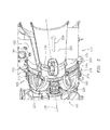
- FIG. 1 illustrates a side view, partly in section, of an air cycle machine including a speed sensor module connected to a fan inlet and diffuser assembly according to an embodiment of the invention
- FIG. 2 illustrates an enlarged, perspective sectional view of the air cycle machine shown in FIG. 1 including a speed sensor module connected to the fan inlet and diffuser assembly according to an embodiment of the invention
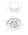
- FIG. 3 illustrates a perspective view of the speed sensor module shown in FIGS. 1 and 2 according to an embodiment of the invention.
- FIG. 4 illustrate a partial perspective view of the fan inlet and diffuser assembly shown in FIGS. 1 and 2 according to an embodiment of the invention.
- Embodiments of an environmental control system having an air cycle machine include a speed sensor module configured for connecting to a fan inlet and diffuser assembly, with embodiments being discussed below in detail.
- the speed sensor module is generally cylindrical in shape and includes a speed sensor residing therein for measuring the rotational speed of a rotating shaft in the air cycle machine.
- the diffuser assembly is coupled to a cylindrical assembly having a circumference that envelops the distal end of the speed sensor module, thereby creating an ejector gap for diverting the flow of cooling air through the air cycle machine.
- FIG. 1 illustrates an example air cycle machine 100 coupled to a speed sensor module 105 and a fan inlet and diffuser assembly 110 (hereinafter "diffuser assembly 110") according to an embodiment of the invention.
- the air cycle machine 100 includes a fan 115 mounted to a compressor (not shown) and a turbine 120 via a shaft 125, which extends along the central axis 130 of the air cycle machine 100.
- the fan 115 and the compressor (not shown) are powered by turbine 120, which rotatably drives the shaft 125 in response to the expansion of the compressed air being conditioned as it passes through the air cycle machine 100.
- the air cycle machine 100 is coupled to a speed sensor module 105 including a speed sensor 135 for measurement of the rotational speed of the shaft 125.
- the speed sensor module 105 is generally cylindrical in shape and is coupled at its proximal end 140, in one embodiment, to the air cycle machine 100 and at its distal end 145 to the diffuser assembly 110
- the speed sensor module 105 is coupled to the diffuser assembly 110 for circulating gaseous cooling ram air through a heat exchanger 102 in an environmental control system (not shown).
- the diffuser assembly 110 includes an axially extending outer horsing 150 coupled to an axially extending inner housing 155, both of which are longitudinally aligned along the central axis 130.
- the diffuser assembly 110 is coupled to, at the proximal end 160, to a generally cylindrical assembly 165 having a circumference that envelops the intermediate cylindrical portion 310 (shown in FIG. 3 )of the speed sensor module 105, thereby creating an ejector gap 185 between the intermediate cylindrical portion 310 (shown in FIG. 3 ) and the cylindrical assembly 165.
- the cylindrical assembly 165 axially extends in direction 195 away from the diffuser assembly 110 and is coupled to the proximate end 160 of the assembly 165.
- the diffuser assembly 110 is provided without the cylindrical assembly 165 and is directly coupled at its proximal end 160 to the distal end 145 of the diffuser assembly 110.
- the exterior housing 150 facilitates airflow through the inlet flow passageway 170 proximate to the inlet side of the fan 115 and into the semi-toriodal shaped ducts 175, 176 while inner housing 155 facilitates air flow from the inlet flow passageways 170, 172 in and out of the outlet flow passageway 180 the ejector gap 185, which is shown and described below in FIG. 2 .
- a detailed view of the speed sensor module 105 and diffuser assembly 110 taken along the line 190 is described in more detail below in FIG. 2 .
- FIG. 2 illustrates a detailed partial perspective view of the speed sensor module 105 coupled to the air cycle machine 100 and diffuser assemble 110 according to an embodiment of the invention.
- the speed sensor module 105 is generally cylindrical in shape and includes a speed sensor 135 residing therein along axis 130 for measuring the rotational speed of the shaft 125 (shown in FIG. 1 ), which is also aligned along the axis 130.
- the speed sensor module 105 is coupled at its proximal end 140 to the air cycle machine 100 through a V-band clamp 205, which facilitates ease of attachment of the module 105.
- the speed sensor module 105 is also coupled at is distal end to the diffuser assembly 110 via a flexible cylindrical boot 210 and a plurality of substantially similar clamping devices 215, 220.
- the speed sensor 135 resides within the speed sensor module 105 and provides for a self contained system, such as a Line Replaceable Unit (LRU), thereby facilitating ease of installation to the air cycle machine 100 as well as simplifying reliability, improving reliability and performance while decreasing system weight.
- LRU Line Replaceable Unit
- the flow of cooling air is induced by the rotating fan 115 and drawn from outside the aircraft through an upstream heat exchanges 102 for conditioning an interior space of the aircraft.
- the cooling air is drawn into the heat exchanger 102, and thence into the inlet flow passageway 170 proximate to the inlet side of the fan 115 via a diffuser assembly 110.
- the cooling air entering the passageway 170 is circumferentially distributed as it flows through the passageway 170 towards the proximate end 160 of the diffuser assembly 110.
- the cooling air flow As the cooling air flow approaches the proximate end 160 of the diffuser assembly 110, it divides into two portions with one flow passing through the inlet flow passageways 170, 172 and into the duct 175 along air flow paths 225 and 226 respectively and continues as the discharge air flow path 228 at the discharge side 229 of the fan 115 ( FIG. 1 ).
- the portion of the flow in the passageways 170, 172 turn 180 degrees and is drawn through the ejector gap 185 by the static pressure differential developed between the flow in passageways 170, 172 and the air flow in path 228 as a second flow during normal operation..
- the speed sensor module 105 including the speed sensor 135 is configured for measuring the speed of the rotating shaft 125 ( FIG. 1 ) and facilitates diagnostics of the air cycle machine 100.
- FIG. 3 illustrates a perspective view of a speed sensor module 105 including a speed sensor 135 according to an embodiment of the invention.
- speed sensor module 105 is generally cylindrical in shape and includes an outer cylindrical portion 305, an intermediate cylindrical portion 310, and an inner cylindrical portion 315 that are all aligned along axis 300.
- Portion 305 has a generally cylindrical-shaped body portion extending from end 306 to end 307 and includes a bore or cavity 308 aligned along axis 300.
- Outer cylindrical portion 305 includes intermediate cylindrical portion 310 and inner cylindrical portion 315 within its bore 308.
- Intermediate cylindrical portion 310 also has a generally cylindrical body that extends from end 311 to end 312 and includes a bore 313 aligned along axis 300.
- Bore 313 includes inner cylindrical portion 315.
- Inner cylindrical portion 315 is generally cylindrical in shape and extends from an open end 316 to a diametrically opposed closed end (not shown), and includes a cavity 318 that is aligned along axis 300.
- Portion 315 encloses a volume within cavity 318, which is provided to receive speed sensor 315.
- each of the portions 305, 310, 315 are coupled to, in one embodiment, a plurality of airfoils 320, 325, and 330, which are symmetrically coupled to each of the portion 305, 310, 315 and emanate from axis 300 outwardly and terminate at outer cylindrical portion 305.
- airfoil 330 may be provided for speed sensor module 105.
- Each airfoil 320, 325, and 330 reside on respective longitudinal axes that is orthogonal to axis 300 of each of portion 305, portion 310, and portion 315.
- air foil 330 includes a longitudinally coextensive inner cavity or aperture (not shown) aligned along axis 302 that emanates inside cavity 318 and traverses each of the portions 305, 310, 315 to provide a channel or groove for receiving one or more connecting wires 335 and electrically connecting the speed sensor 135 to an aircraft (not shown).
- speed sensor module 105 is coupled to the air cycle machine 100 at end 306 and speed sensor 135 provides for measuring the rotation of shaft 125 ( FIG. 1 ) as the cooling air traverses through each of the cylindrical portions 305, 310, 315 and into the diffuser assembly 110.
- FIG. 4 illustrates a partial perspective view of a cylindrical assembly 165 of a diffuser assembly 110 according to an embodiment of the invention.
- diffuser assembly 110 is coupled, at the proximal end 160, to a generally cylindrical assembly 165 in order to create an ejector gap 185 between the sensor module 105 (shown in FIG. 1 ) and the diffuser assembly 110 (also shown in FIG. 1 ).
- the cylindrical assembly 165 has a through bore 402 aligned along bore axis 404 and includes a proximate portion 405 coupled to a distal portion 410.
- the proximate portion 405 has a generally cylindrical shaped body from a first end 415 having a first diameter that terminates into a second end 420 having a second internal diameter.
- the first diameter is larger than the second diameter thereby creating a tapered portion 405.
- proximate portion 405 may have a uniform diameter from first end 415 to second end 420.
- proximate portion 405 is coupled to distal portion 410 at end 420.
- Distal portion 410 is also generally cylindrical in shape and is coupled, at its proximate end 425, to proximate portion 405 and at its distal end 430 to the proximal end 160 of the diffuser assembly 110.
- the internal diameter of the distal portion 410 may be uniform from end 425 to end 430, or tapered to conform to the diameter of the proximal end 160.
- the technical effects and benefits of exemplary embodiments include an air cycle machine coupled to a speed sensor module and a fan inlet and diffuser assembly. Also, the diffuser assembly is coupled to a cylindrical assembly having a circumference that envelops the distal end of the speed sensor module, thereby creating an ejector gap.
Landscapes
- Engineering & Computer Science (AREA)
- Mechanical Engineering (AREA)
- General Engineering & Computer Science (AREA)
- Health & Medical Sciences (AREA)
- General Health & Medical Sciences (AREA)
- Pulmonology (AREA)
- Aviation & Aerospace Engineering (AREA)
- Structures Of Non-Positive Displacement Pumps (AREA)
- Air Conditioning Control Device (AREA)
- Central Air Conditioning (AREA)
Abstract
Description
- This invention generally relates to an air cycle machine for environmental control systems (ECSs) and, more particularly, to a speed sensor module that may be selectively connected to a fan inlet and diffuser assembly for an air cycle machine,
- Conventional aircraft environmental control systems (ECSs) incorporate an air cycle machine, also referred to as an air cycle cooling machine, for use in cooling and dehumidifying air for supply to the aircraft cabin for occupant comfort, Such air cycle machines may comprise two or more wheels disposed at axially spaced intervals along a common shaft. The wheels are part of, for example, a compressor rotor, a turbine rotor, a fan rotor or an additional turbine rotor or an additional compressor rotor. In some cases the turbine or turbine drive both the compressor and the fan.
- On aircraft powered by turbine engines, the air to be conditioned in the air cycle machine is typically compressed air bled from one or more of the compressor stages of the turbine engine, In conventional systems, this bleed air is passed through the air cycle machine compressor wherein it is further compressed. The compressed air is passed through a condensing heat exchanger to cool the compressed air sufficiently to remove moisture and dehumidify the air. The dehumidified compressed air is expanded in the turbine of the air cycle machine to both extract energy from the compressed air so as to drive the shaft and also to cool the expanded turbine exhaust air before it is supplied to the cabin as conditioned cooling air. A speed sensor is generally used to measure the rotational speed of the shaft in order to diagnose faults or issues with performance. However, installing the speed sensor within the air cycle machine requires threading the associated speed sensor connection through the attached ducting and housings, resulting in a complex installation process.
- According to one aspect of the invention, an environmental control system , includes an air cycle machine for conditioning an interior space with cooling air, the air cycle machine including a fan coupled to a shaft that rotates about a shaft axis, the fan being located at a distal end of the air cycle machine; a speed sensor module having a speed sensor for sensing a rotational speed of the shaft; wherein the speed sensor module includes an outer portion having a first bore aligned on the shaft axis, an intermediate portion having a second bore aligned on the shaft axis, and an inner portion aligned on the shaft axis; and a diffuser assembly including a cylindrical assembly for ducting a first portion of the cooling air to an inlet side of the fan and for communicating a second portion of the cooling air directly to a discharge side of the fan without passing the inlet side.
- According to another aspect of the invention, a speed sensor module in an environmental control system includes an outer portion aligned having a first bore aligned on a shaft axis; an intermediate portion having a second bore aligned on the shaft axis; and an inner portion aligned on the shaft axis, the inner portion including a speed sensor for sensing a rotational speed of the shaft; where the outer portion is configured for surrounding each of the intermediate portion and the inner portion within the first bore.
- Other aspects, features, and techniques of the invention will become more apparent from the following description taken in conjunction with the drawings,
- Referring now to the drawings wherein like elements are numbered alike in the FIGURES:
-
FIG. 1 illustrates a side view, partly in section, of an air cycle machine including a speed sensor module connected to a fan inlet and diffuser assembly according to an embodiment of the invention; -
FIG. 2 illustrates an enlarged, perspective sectional view of the air cycle machine shown inFIG. 1 including a speed sensor module connected to the fan inlet and diffuser assembly according to an embodiment of the invention; -
FIG. 3 illustrates a perspective view of the speed sensor module shown inFIGS. 1 and2 according to an embodiment of the invention; and -
FIG. 4 illustrate a partial perspective view of the fan inlet and diffuser assembly shown inFIGS. 1 and2 according to an embodiment of the invention. - Embodiments of an environmental control system having an air cycle machine include a speed sensor module configured for connecting to a fan inlet and diffuser assembly, with embodiments being discussed below in detail. The speed sensor module is generally cylindrical in shape and includes a speed sensor residing therein for measuring the rotational speed of a rotating shaft in the air cycle machine. Also, the diffuser assembly is coupled to a cylindrical assembly having a circumference that envelops the distal end of the speed sensor module, thereby creating an ejector gap for diverting the flow of cooling air through the air cycle machine.
- Referring to the drawings,
FIG. 1 illustrates an exampleair cycle machine 100 coupled to aspeed sensor module 105 and a fan inlet and diffuser assembly 110 (hereinafter "diffuser assembly 110") according to an embodiment of the invention. Particularly, theair cycle machine 100 includes afan 115 mounted to a compressor (not shown) and aturbine 120 via ashaft 125, which extends along thecentral axis 130 of theair cycle machine 100. In an embodiment, thefan 115 and the compressor (not shown) are powered byturbine 120, which rotatably drives theshaft 125 in response to the expansion of the compressed air being conditioned as it passes through theair cycle machine 100. Also shown, theair cycle machine 100 is coupled to aspeed sensor module 105 including aspeed sensor 135 for measurement of the rotational speed of theshaft 125. Thespeed sensor module 105 is generally cylindrical in shape and is coupled at itsproximal end 140, in one embodiment, to theair cycle machine 100 and at itsdistal end 145 to thediffuser assembly 110 - Also, the
speed sensor module 105 is coupled to thediffuser assembly 110 for circulating gaseous cooling ram air through aheat exchanger 102 in an environmental control system (not shown). Particularly, thediffuser assembly 110 includes an axially extendingouter horsing 150 coupled to an axially extendinginner housing 155, both of which are longitudinally aligned along thecentral axis 130. Thediffuser assembly 110 is coupled to, at theproximal end 160, to a generallycylindrical assembly 165 having a circumference that envelops the intermediate cylindrical portion 310 (shown inFIG. 3 )of thespeed sensor module 105, thereby creating anejector gap 185 between the intermediate cylindrical portion 310 (shown inFIG. 3 ) and thecylindrical assembly 165. Thecylindrical assembly 165 axially extends indirection 195 away from thediffuser assembly 110 and is coupled to theproximate end 160 of theassembly 165. In another embodiment, thediffuser assembly 110 is provided without thecylindrical assembly 165 and is directly coupled at itsproximal end 160 to thedistal end 145 of thediffuser assembly 110. Also, theexterior housing 150 facilitates airflow through theinlet flow passageway 170 proximate to the inlet side of thefan 115 and into the semi-toriodal shapedducts inner housing 155 facilitates air flow from theinlet flow passageways outlet flow passageway 180 theejector gap 185, which is shown and described below inFIG. 2 . A detailed view of thespeed sensor module 105 anddiffuser assembly 110 taken along theline 190 is described in more detail below inFIG. 2 . -
FIG. 2 illustrates a detailed partial perspective view of thespeed sensor module 105 coupled to theair cycle machine 100 and diffuser assemble 110 according to an embodiment of the invention. Particularly, thespeed sensor module 105 is generally cylindrical in shape and includes aspeed sensor 135 residing therein alongaxis 130 for measuring the rotational speed of the shaft 125 (shown inFIG. 1 ), which is also aligned along theaxis 130. Thespeed sensor module 105 is coupled at itsproximal end 140 to theair cycle machine 100 through a V-band clamp 205, which facilitates ease of attachment of themodule 105. Thespeed sensor module 105 is also coupled at is distal end to thediffuser assembly 110 via a flexiblecylindrical boot 210 and a plurality of substantiallysimilar clamping devices speed sensor 135 resides within thespeed sensor module 105 and provides for a self contained system, such as a Line Replaceable Unit (LRU), thereby facilitating ease of installation to theair cycle machine 100 as well as simplifying reliability, improving reliability and performance while decreasing system weight. - In operation, and referring to
FIGS. 1 and2 , the flow of cooling air, for example ram air, is induced by the rotatingfan 115 and drawn from outside the aircraft through anupstream heat exchanges 102 for conditioning an interior space of the aircraft. In one example, the cooling air is drawn into theheat exchanger 102, and thence into theinlet flow passageway 170 proximate to the inlet side of thefan 115 via adiffuser assembly 110. The cooling air entering thepassageway 170 is circumferentially distributed as it flows through thepassageway 170 towards theproximate end 160 of thediffuser assembly 110. As the cooling air flow approaches theproximate end 160 of thediffuser assembly 110, it divides into two portions with one flow passing through theinlet flow passageways duct 175 alongair flow paths air flow path 228 at thedischarge side 229 of the fan 115 (FIG. 1 ). The portion of the flow in thepassageways turn 180 degrees and is drawn through theejector gap 185 by the static pressure differential developed between the flow inpassageways path 228 as a second flow during normal operation.. During a surge such as, when the heat exchanger is blocked, the air flows from thedischarge side 229 into thepassageway 170 and helps to prevent a catastrophic failure of theair cycle machine 100. It is to be appreciated that thespeed sensor module 105 including thespeed sensor 135 is configured for measuring the speed of the rotating shaft 125 (FIG. 1 ) and facilitates diagnostics of theair cycle machine 100. -
FIG. 3 illustrates a perspective view of aspeed sensor module 105 including aspeed sensor 135 according to an embodiment of the invention. Particularly,speed sensor module 105 is generally cylindrical in shape and includes an outercylindrical portion 305, an intermediatecylindrical portion 310, and an innercylindrical portion 315 that are all aligned alongaxis 300.Portion 305 has a generally cylindrical-shaped body portion extending fromend 306 toend 307 and includes a bore orcavity 308 aligned alongaxis 300. Outercylindrical portion 305 includes intermediatecylindrical portion 310 and innercylindrical portion 315 within itsbore 308. Intermediatecylindrical portion 310 also has a generally cylindrical body that extends fromend 311 toend 312 and includes abore 313 aligned alongaxis 300. Bore 313 includes innercylindrical portion 315. Innercylindrical portion 315 is generally cylindrical in shape and extends from anopen end 316 to a diametrically opposed closed end (not shown), and includes acavity 318 that is aligned alongaxis 300.Portion 315 encloses a volume withincavity 318, which is provided to receivespeed sensor 315. Further, each of theportions airfoils portion axis 300 outwardly and terminate at outercylindrical portion 305. In another embodiment, additional airfoils, such asairfoil 330, may be provided forspeed sensor module 105. Eachairfoil axis 300 of each ofportion 305,portion 310, andportion 315. In one embodiment,air foil 330 includes a longitudinally coextensive inner cavity or aperture (not shown) aligned alongaxis 302 that emanates insidecavity 318 and traverses each of theportions wires 335 and electrically connecting thespeed sensor 135 to an aircraft (not shown). It is to be appreciated that thespeed sensor module 105 is coupled to theair cycle machine 100 atend 306 andspeed sensor 135 provides for measuring the rotation of shaft 125 (FIG. 1 ) as the cooling air traverses through each of thecylindrical portions diffuser assembly 110. -
FIG. 4 illustrates a partial perspective view of acylindrical assembly 165 of adiffuser assembly 110 according to an embodiment of the invention. Particularly,diffuser assembly 110 is coupled, at theproximal end 160, to a generallycylindrical assembly 165 in order to create anejector gap 185 between the sensor module 105 (shown inFIG. 1 ) and the diffuser assembly 110 (also shown inFIG. 1 ). Thecylindrical assembly 165 has a throughbore 402 aligned alongbore axis 404 and includes aproximate portion 405 coupled to adistal portion 410. Theproximate portion 405 has a generally cylindrical shaped body from afirst end 415 having a first diameter that terminates into asecond end 420 having a second internal diameter. In one embodiment, the first diameter is larger than the second diameter thereby creating a taperedportion 405. However, in another embodiment,proximate portion 405 may have a uniform diameter fromfirst end 415 tosecond end 420. Also,proximate portion 405 is coupled todistal portion 410 atend 420.Distal portion 410 is also generally cylindrical in shape and is coupled, at itsproximate end 425, toproximate portion 405 and at itsdistal end 430 to theproximal end 160 of thediffuser assembly 110. In embodiments, the internal diameter of thedistal portion 410 may be uniform fromend 425 to end 430, or tapered to conform to the diameter of theproximal end 160. - The technical effects and benefits of exemplary embodiments include an air cycle machine coupled to a speed sensor module and a fan inlet and diffuser assembly. Also, the diffuser assembly is coupled to a cylindrical assembly having a circumference that envelops the distal end of the speed sensor module, thereby creating an ejector gap.
- The terminology used herein is for the purpose of describing particular embodiments only and is not intended to be limiting of the invention. While the description of the present invention has been presented for purposes of illustration and description, it is not intended to be exhaustive or limited to the invention in the form disclosed. Many modifications, variations, alterations, substitutions, or equivalent arrangement not hereto described will be apparent to those of ordinary skill in the art without departing from the scope and spirit of the invention. Additionally, while various embodiment of the invention have been described, it is to be understood that aspects of the invention may include only some of the described embodiments. Accordingly, the invention is not to be seen as limited by the foregoing description, but is only limited by the scope of the appended claims.
Claims (15)
- An environmental control system, comprising:an air cycle machine (100) for conditioning an interior space with cooling air, the air cycle machine including a fan coupled to a shaft (125) that rotates about a shaft axis (300), the fan being located at a distal end of the air cycle machine;a speed sensor module (105) having a speed sensor (135) for sensing a rotational speed of the shaft (125); wherein the speed sensor module includes an outer portion (305) having a first bore (308) aligned on the shaft axis (3009, an intermediate portion (310) having a second bore (313) aligned on the shaft axis, and an inner portion (315) aligned on the shaft axis; anda diffuser assembly (110) including a cylindrical assembly for ducting a first portion of the cooling air to an inlet side of the fan and for communicating a second portion of the cooling air directly to a discharge side of the fan without passing the inlet side.
- The environmental control system of claim 1, wherein the outer portion (305) includes a first end proximate to the distal end and a second end diametrically opposite the first end.
- The environmental control system of claim 1, wherein the cylindrical assembly is operatively coupled to the diffuser assembly (110) for facilitating the communicating of the second portion of the cooling air, or wherein the outer portion is configured for receiving each of the intermediate portion and the inner portion within the first bore, or wherein the intermediate portion is configured for receiving the inner portion within the second bore, or wherein the speed sensor module is configured for receiving the speed sensor within an inner cavity located in the inner portion, or wherein the diffuser assembly (110) comprises an axially extending outer housing configured for mounting to the outer portion of the speed sensor module and an axially extending inner housing disposed coaxially within the outer housing, the inner housing being configured for connecting to the second cylindrical portion.
- The environmental control system of claim 1, further comprising at least one air foil (320, 325, 330) traversing each of the outer (305), intermediate (310), and inner (315) portions.
- The environmental control system of claim 4, wherein a longitudinal axis of the at least one air foil is orthogonal to of the shaft axis (300) of each of the outer (305), intermediate (310), and inner (315) portions.
- The environmental control system of claim 4, wherein the at least one air foil comprises an aperture that is longitudinally coextensive with a body portion of the at least one air foil.
- The environmental control system of claim 6, wherein the aperture is configured for receiving an electrical connection for the speed sensor.
- The environmental control system of claim 2, wherein the cylindrical assembly includes a first cylindrical portion proximate to the second end of the speed sensor module (105) and at least a second cylindrical portion diametrically opposed to the first cylindrical portion, wherein the first cylindrical portion being coupled to the second cylindrical portion and including a second bore aligned along a second bore axis.
- A speed sensor module (105) in an environmental control system, comprising:an outer portion (305) aligned having a first bore (308) aligned on a shaft axis (300);an intermediate portion (310) having a second bore (313) aligned on the shaft axis; andan inner portion (315) aligned on the shaft axis (300), the inner portion including a speed sensor for sensing a rotational speed of the shaft;wherein the outer portion (305) is configured for surrounding each of the intermediate portion and the inner portion within the first bore.
- The speed sensor module (105) of claim 9, wherein the intermediate portion (310) is configured for surrounding the inner portion within the second bore (313).
- The speed sensor module of claim 9, further comprising at least one air foil (320, 325, 330) traversing each of the outer (305), intermediate (310), and inner portions (315),
- The speed sensor module of claim 11, wherein the at least one air foil (320, 325, 330) is orthogonal to a tangent at respective surfaces of each of the outer, intermediate, and inner portions.
- The speed sensor module of claim 11, wherein the at least one air foil (320, 325, 330) comprises an aperture that is longitudinally coextensive with a body portion of the at least one air foil.
- The speed sensor module of claim 13, wherein the aperture is configured for receiving an electrical connection for the speed sensor.
- The speed sensor module of claim 9, wherein the speed sensor module (105) is configured for receiving the speed sensor within an inner cavity disposed in the inner portion.
Applications Claiming Priority (1)
| Application Number | Priority Date | Filing Date | Title |
|---|---|---|---|
| US13/347,979 US9132919B2 (en) | 2012-01-11 | 2012-01-11 | Speed sensor module and diffuser assembly |
Publications (2)
| Publication Number | Publication Date |
|---|---|
| EP2615031A1 true EP2615031A1 (en) | 2013-07-17 |
| EP2615031B1 EP2615031B1 (en) | 2014-12-17 |
Family
ID=47715838
Family Applications (1)
| Application Number | Title | Priority Date | Filing Date |
|---|---|---|---|
| EP13150802.0A Active EP2615031B1 (en) | 2012-01-11 | 2013-01-10 | Speed sensor module and diffuser assembly |
Country Status (4)
| Country | Link |
|---|---|
| US (1) | US9132919B2 (en) |
| EP (1) | EP2615031B1 (en) |
| JP (1) | JP2013144540A (en) |
| IL (1) | IL224182A (en) |
Cited By (1)
| Publication number | Priority date | Publication date | Assignee | Title |
|---|---|---|---|---|
| EP3031725A1 (en) * | 2014-12-08 | 2016-06-15 | Hamilton Sundstrand Corporation | Air cycle machine speed diagnostic |
Families Citing this family (10)
| Publication number | Priority date | Publication date | Assignee | Title |
|---|---|---|---|---|
| US10634051B2 (en) * | 2012-01-09 | 2020-04-28 | United Technologies Corporation | Geared turbofan engine with low pressure environmental control system for aircraft |
| US8763458B2 (en) * | 2012-01-11 | 2014-07-01 | Hamilton Sundstrand Corporation | Speed sensor module |
| US10661906B2 (en) | 2014-09-23 | 2020-05-26 | Hamilton Sundstrand Corporation | Fan and compressor housing for an air cycle machine |
| US9989070B2 (en) | 2014-10-01 | 2018-06-05 | Hamilton Sundstrand Corporation | Air cycle machine strut plate assembly |
| US10619650B2 (en) * | 2016-05-06 | 2020-04-14 | Hamilton Sundstrand Corporation | Air cycle machine fan and compressor housing |
| US10465694B2 (en) * | 2017-04-05 | 2019-11-05 | Hamilton Sundstrand Corporation | Fan inlet diffuser housing with conductive composite body |
| US10788046B2 (en) | 2018-01-05 | 2020-09-29 | Hamilton Sundstrand Corporation | Fan and compressor housing for an air cycle machine |
| CN112413919B (en) * | 2020-12-21 | 2022-06-07 | 深圳供电局有限公司 | Low-temperature refrigerator |
| CN115520394A (en) * | 2022-10-24 | 2022-12-27 | 陕西秦科世博航空科技有限公司 | A ram air collecting diffuser for an aircraft air conditioning system |
| US20260092941A1 (en) * | 2024-10-01 | 2026-04-02 | The Boeing Company | Air cycle machine speed sensor assembly |
Citations (3)
| Publication number | Priority date | Publication date | Assignee | Title |
|---|---|---|---|---|
| GB979936A (en) * | 1961-10-04 | 1965-01-06 | Sulzer Ag | Apparatus for cooling gases |
| US5133194A (en) * | 1991-02-04 | 1992-07-28 | United Technologies Corporation | Air cycle machine and fan inlet/diffuser therefor |
| DE102005010921A1 (en) * | 2004-07-15 | 2006-02-09 | Siemens Ag | turbocharger |
Family Cites Families (13)
| Publication number | Priority date | Publication date | Assignee | Title |
|---|---|---|---|---|
| JPH0448167A (en) * | 1990-06-15 | 1992-02-18 | Nippondenso Co Ltd | Refrigerating cycle device |
| JPH04219420A (en) * | 1990-12-18 | 1992-08-10 | Yanmar Diesel Engine Co Ltd | Exhaust gas diffuser of gas turbine |
| DE10015570B4 (en) | 2000-03-29 | 2007-11-22 | Airbus Deutschland Gmbh | Arrangement for forced guidance of a cooling air flow within a refrigeration unit for a commercial aircraft |
| US6257003B1 (en) * | 2000-08-04 | 2001-07-10 | Hamilton Sundstrand Corporation | Environmental control system utilizing two air cycle machines |
| WO2002099288A1 (en) * | 2001-06-06 | 2002-12-12 | Howden Power A/S | An air outlet unit for a large blower assembly |
| JP2003214190A (en) * | 2002-01-22 | 2003-07-30 | Ebara Corp | Gas turbine device |
| US6701715B2 (en) | 2002-05-02 | 2004-03-09 | Honeywell International, Inc. | Variable geometry ejector for a bleed air system using integral ejector exit pressure feedback |
| JP2004245193A (en) * | 2003-02-17 | 2004-09-02 | Sumitomo Precision Prod Co Ltd | Air cycle air conditioner for aircraft |
| DE102005029764B4 (en) * | 2005-06-27 | 2010-11-11 | Continental Automotive France | Sensor for measuring the speed of a turbo shaft |
| GB2428087B (en) * | 2005-07-07 | 2009-12-23 | Rolls Royce Plc | A gas turbine engine incorporating an engine monitoring arrangement for monitoring gas constituents in an exhaust flow |
| US7536864B2 (en) | 2005-12-07 | 2009-05-26 | General Electric Company | Variable motive nozzle ejector for use with turbine engines |
| JP5263024B2 (en) * | 2009-06-18 | 2013-08-14 | 株式会社日立製作所 | Rotation angle detection device and rotation speed detection device |
| US8979490B2 (en) * | 2011-09-29 | 2015-03-17 | Hamilton Sundstrand Corporation | Fan inlet diffuser housing riveted center body retention |
-
2012
- 2012-01-11 US US13/347,979 patent/US9132919B2/en active Active
-
2013
- 2013-01-10 IL IL224182A patent/IL224182A/en active IP Right Grant
- 2013-01-10 EP EP13150802.0A patent/EP2615031B1/en active Active
- 2013-01-11 JP JP2013003109A patent/JP2013144540A/en not_active Ceased
Patent Citations (3)
| Publication number | Priority date | Publication date | Assignee | Title |
|---|---|---|---|---|
| GB979936A (en) * | 1961-10-04 | 1965-01-06 | Sulzer Ag | Apparatus for cooling gases |
| US5133194A (en) * | 1991-02-04 | 1992-07-28 | United Technologies Corporation | Air cycle machine and fan inlet/diffuser therefor |
| DE102005010921A1 (en) * | 2004-07-15 | 2006-02-09 | Siemens Ag | turbocharger |
Cited By (2)
| Publication number | Priority date | Publication date | Assignee | Title |
|---|---|---|---|---|
| EP3031725A1 (en) * | 2014-12-08 | 2016-06-15 | Hamilton Sundstrand Corporation | Air cycle machine speed diagnostic |
| US10267325B2 (en) | 2014-12-08 | 2019-04-23 | Hamilton Sundstrand Corporation | Air cycle machine speed diagnostic |
Also Published As
| Publication number | Publication date |
|---|---|
| US9132919B2 (en) | 2015-09-15 |
| IL224182A (en) | 2016-04-21 |
| US20130177399A1 (en) | 2013-07-11 |
| JP2013144540A (en) | 2013-07-25 |
| EP2615031B1 (en) | 2014-12-17 |
Similar Documents
| Publication | Publication Date | Title |
|---|---|---|
| US9132919B2 (en) | Speed sensor module and diffuser assembly | |
| EP2837563B1 (en) | Enhanced motor cooling system and method | |
| JP5788915B2 (en) | Particle separator | |
| EP2602191A1 (en) | Motor driven cabin air compressor with variable diffuser | |
| US9267514B2 (en) | Bearing cooling control in an air cycle machine | |
| CN104033477B (en) | Air bearing shaft | |
| US20160281721A1 (en) | Bearing cooling flow and energy recovery systems | |
| CN107345528B (en) | Air cycle machine fan and compressor housing | |
| CN110214223B (en) | Asymmetric inlet particle separator system | |
| EP3184824B1 (en) | Thermal enhancement of cabin air compressor motor cooling | |
| JP2011526663A (en) | Axial-flow centrifugal compressor having a system for adjusting the gap | |
| US9989070B2 (en) | Air cycle machine strut plate assembly | |
| EP3181831B1 (en) | Bearing thermal management system and method | |
| EP2378086A2 (en) | Variable turbine nozzle and valve | |
| US9914542B2 (en) | Ram air fan housing | |
| EP3508424A1 (en) | Fan and compressor housing for an air cycle machine | |
| US8763458B2 (en) | Speed sensor module | |
| CN105743261B (en) | Motor shell component for cabin air compressor | |
| US9057283B2 (en) | Bearing cooling system for flexible shaft turbomachine | |
| CN107013267B (en) | Bypass housing in an air cycle machine | |
| US20240017836A1 (en) | Air cycle machine with integral heat exchanger | |
| US20170102002A1 (en) | Fan shaft for air cycle machine | |
| CN105736407B (en) | Drainage hole in ram-air blower-casting | |
| EP4306417A1 (en) | Air cycle machine with integral heat exchanger | |
| US20240017835A1 (en) | Air cycle machine with integral heat exchanger |
Legal Events
| Date | Code | Title | Description |
|---|---|---|---|
| PUAI | Public reference made under article 153(3) epc to a published international application that has entered the european phase |
Free format text: ORIGINAL CODE: 0009012 |
|
| AK | Designated contracting states |
Kind code of ref document: A1 Designated state(s): AL AT BE BG CH CY CZ DE DK EE ES FI FR GB GR HR HU IE IS IT LI LT LU LV MC MK MT NL NO PL PT RO RS SE SI SK SM TR |
|
| AX | Request for extension of the european patent |
Extension state: BA ME |
|
| 17P | Request for examination filed |
Effective date: 20140117 |
|
| RBV | Designated contracting states (corrected) |
Designated state(s): AL AT BE BG CH CY CZ DE DK EE ES FI FR GB GR HR HU IE IS IT LI LT LU LV MC MK MT NL NO PL PT RO RS SE SI SK SM TR |
|
| GRAP | Despatch of communication of intention to grant a patent |
Free format text: ORIGINAL CODE: EPIDOSNIGR1 |
|
| RIC1 | Information provided on ipc code assigned before grant |
Ipc: B64D 13/06 20060101ALI20140610BHEP Ipc: B64D 13/00 20060101AFI20140610BHEP Ipc: F25B 9/00 20060101ALI20140610BHEP |
|
| INTG | Intention to grant announced |
Effective date: 20140704 |
|
| RIN1 | Information on inventor provided before grant (corrected) |
Inventor name: MCAULIFFE, CHRISTOPHER Inventor name: ZAGER, MICHAEL |
|
| GRAS | Grant fee paid |
Free format text: ORIGINAL CODE: EPIDOSNIGR3 |
|
| GRAA | (expected) grant |
Free format text: ORIGINAL CODE: 0009210 |
|
| AK | Designated contracting states |
Kind code of ref document: B1 Designated state(s): AL AT BE BG CH CY CZ DE DK EE ES FI FR GB GR HR HU IE IS IT LI LT LU LV MC MK MT NL NO PL PT RO RS SE SI SK SM TR |
|
| REG | Reference to a national code |
Ref country code: GB Ref legal event code: FG4D |
|
| REG | Reference to a national code |
Ref country code: CH Ref legal event code: EP |
|
| REG | Reference to a national code |
Ref country code: IE Ref legal event code: FG4D |
|
| REG | Reference to a national code |
Ref country code: AT Ref legal event code: REF Ref document number: 701686 Country of ref document: AT Kind code of ref document: T Effective date: 20150115 |
|
| REG | Reference to a national code |
Ref country code: DE Ref legal event code: R096 Ref document number: 602013000599 Country of ref document: DE Effective date: 20150212 |
|
| PG25 | Lapsed in a contracting state [announced via postgrant information from national office to epo] |
Ref country code: NO Free format text: LAPSE BECAUSE OF FAILURE TO SUBMIT A TRANSLATION OF THE DESCRIPTION OR TO PAY THE FEE WITHIN THE PRESCRIBED TIME-LIMIT Effective date: 20150317 Ref country code: LT Free format text: LAPSE BECAUSE OF FAILURE TO SUBMIT A TRANSLATION OF THE DESCRIPTION OR TO PAY THE FEE WITHIN THE PRESCRIBED TIME-LIMIT Effective date: 20141217 Ref country code: FI Free format text: LAPSE BECAUSE OF FAILURE TO SUBMIT A TRANSLATION OF THE DESCRIPTION OR TO PAY THE FEE WITHIN THE PRESCRIBED TIME-LIMIT Effective date: 20141217 |
|
| REG | Reference to a national code |
Ref country code: LT Ref legal event code: MG4D |
|
| PG25 | Lapsed in a contracting state [announced via postgrant information from national office to epo] |
Ref country code: GR Free format text: LAPSE BECAUSE OF FAILURE TO SUBMIT A TRANSLATION OF THE DESCRIPTION OR TO PAY THE FEE WITHIN THE PRESCRIBED TIME-LIMIT Effective date: 20150318 Ref country code: HR Free format text: LAPSE BECAUSE OF FAILURE TO SUBMIT A TRANSLATION OF THE DESCRIPTION OR TO PAY THE FEE WITHIN THE PRESCRIBED TIME-LIMIT Effective date: 20141217 Ref country code: LV Free format text: LAPSE BECAUSE OF FAILURE TO SUBMIT A TRANSLATION OF THE DESCRIPTION OR TO PAY THE FEE WITHIN THE PRESCRIBED TIME-LIMIT Effective date: 20141217 Ref country code: RS Free format text: LAPSE BECAUSE OF FAILURE TO SUBMIT A TRANSLATION OF THE DESCRIPTION OR TO PAY THE FEE WITHIN THE PRESCRIBED TIME-LIMIT Effective date: 20141217 Ref country code: SE Free format text: LAPSE BECAUSE OF FAILURE TO SUBMIT A TRANSLATION OF THE DESCRIPTION OR TO PAY THE FEE WITHIN THE PRESCRIBED TIME-LIMIT Effective date: 20141217 |
|
| REG | Reference to a national code |
Ref country code: AT Ref legal event code: MK05 Ref document number: 701686 Country of ref document: AT Kind code of ref document: T Effective date: 20141217 |
|
| PG25 | Lapsed in a contracting state [announced via postgrant information from national office to epo] |
Ref country code: NL Free format text: LAPSE BECAUSE OF FAILURE TO SUBMIT A TRANSLATION OF THE DESCRIPTION OR TO PAY THE FEE WITHIN THE PRESCRIBED TIME-LIMIT Effective date: 20141217 |
|
| PG25 | Lapsed in a contracting state [announced via postgrant information from national office to epo] |
Ref country code: PT Free format text: LAPSE BECAUSE OF FAILURE TO SUBMIT A TRANSLATION OF THE DESCRIPTION OR TO PAY THE FEE WITHIN THE PRESCRIBED TIME-LIMIT Effective date: 20150417 Ref country code: RO Free format text: LAPSE BECAUSE OF FAILURE TO SUBMIT A TRANSLATION OF THE DESCRIPTION OR TO PAY THE FEE WITHIN THE PRESCRIBED TIME-LIMIT Effective date: 20141217 Ref country code: CZ Free format text: LAPSE BECAUSE OF FAILURE TO SUBMIT A TRANSLATION OF THE DESCRIPTION OR TO PAY THE FEE WITHIN THE PRESCRIBED TIME-LIMIT Effective date: 20141217 Ref country code: SK Free format text: LAPSE BECAUSE OF FAILURE TO SUBMIT A TRANSLATION OF THE DESCRIPTION OR TO PAY THE FEE WITHIN THE PRESCRIBED TIME-LIMIT Effective date: 20141217 Ref country code: ES Free format text: LAPSE BECAUSE OF FAILURE TO SUBMIT A TRANSLATION OF THE DESCRIPTION OR TO PAY THE FEE WITHIN THE PRESCRIBED TIME-LIMIT Effective date: 20141217 Ref country code: EE Free format text: LAPSE BECAUSE OF FAILURE TO SUBMIT A TRANSLATION OF THE DESCRIPTION OR TO PAY THE FEE WITHIN THE PRESCRIBED TIME-LIMIT Effective date: 20141217 |
|
| REG | Reference to a national code |
Ref country code: DE Ref legal event code: R119 Ref document number: 602013000599 Country of ref document: DE |
|
| PG25 | Lapsed in a contracting state [announced via postgrant information from national office to epo] |
Ref country code: AT Free format text: LAPSE BECAUSE OF FAILURE TO SUBMIT A TRANSLATION OF THE DESCRIPTION OR TO PAY THE FEE WITHIN THE PRESCRIBED TIME-LIMIT Effective date: 20141217 Ref country code: PL Free format text: LAPSE BECAUSE OF FAILURE TO SUBMIT A TRANSLATION OF THE DESCRIPTION OR TO PAY THE FEE WITHIN THE PRESCRIBED TIME-LIMIT Effective date: 20141217 Ref country code: IS Free format text: LAPSE BECAUSE OF FAILURE TO SUBMIT A TRANSLATION OF THE DESCRIPTION OR TO PAY THE FEE WITHIN THE PRESCRIBED TIME-LIMIT Effective date: 20150417 Ref country code: LU Free format text: LAPSE BECAUSE OF FAILURE TO SUBMIT A TRANSLATION OF THE DESCRIPTION OR TO PAY THE FEE WITHIN THE PRESCRIBED TIME-LIMIT Effective date: 20150110 |
|
| PG25 | Lapsed in a contracting state [announced via postgrant information from national office to epo] |
Ref country code: MC Free format text: LAPSE BECAUSE OF FAILURE TO SUBMIT A TRANSLATION OF THE DESCRIPTION OR TO PAY THE FEE WITHIN THE PRESCRIBED TIME-LIMIT Effective date: 20141217 |
|
| PLBE | No opposition filed within time limit |
Free format text: ORIGINAL CODE: 0009261 |
|
| STAA | Information on the status of an ep patent application or granted ep patent |
Free format text: STATUS: NO OPPOSITION FILED WITHIN TIME LIMIT |
|
| PG25 | Lapsed in a contracting state [announced via postgrant information from national office to epo] |
Ref country code: DE Free format text: LAPSE BECAUSE OF NON-PAYMENT OF DUE FEES Effective date: 20150801 Ref country code: DK Free format text: LAPSE BECAUSE OF FAILURE TO SUBMIT A TRANSLATION OF THE DESCRIPTION OR TO PAY THE FEE WITHIN THE PRESCRIBED TIME-LIMIT Effective date: 20141217 |
|
| REG | Reference to a national code |
Ref country code: IE Ref legal event code: MM4A |
|
| 26N | No opposition filed |
Effective date: 20150918 |
|
| REG | Reference to a national code |
Ref country code: FR Ref legal event code: PLFP Year of fee payment: 4 |
|
| PG25 | Lapsed in a contracting state [announced via postgrant information from national office to epo] |
Ref country code: IE Free format text: LAPSE BECAUSE OF NON-PAYMENT OF DUE FEES Effective date: 20150110 |
|
| PG25 | Lapsed in a contracting state [announced via postgrant information from national office to epo] |
Ref country code: SI Free format text: LAPSE BECAUSE OF FAILURE TO SUBMIT A TRANSLATION OF THE DESCRIPTION OR TO PAY THE FEE WITHIN THE PRESCRIBED TIME-LIMIT Effective date: 20141217 |
|
| PG25 | Lapsed in a contracting state [announced via postgrant information from national office to epo] |
Ref country code: BE Free format text: LAPSE BECAUSE OF FAILURE TO SUBMIT A TRANSLATION OF THE DESCRIPTION OR TO PAY THE FEE WITHIN THE PRESCRIBED TIME-LIMIT Effective date: 20141217 |
|
| REG | Reference to a national code |
Ref country code: CH Ref legal event code: PL |
|
| PG25 | Lapsed in a contracting state [announced via postgrant information from national office to epo] |
Ref country code: LI Free format text: LAPSE BECAUSE OF NON-PAYMENT OF DUE FEES Effective date: 20160131 Ref country code: CH Free format text: LAPSE BECAUSE OF NON-PAYMENT OF DUE FEES Effective date: 20160131 |
|
| REG | Reference to a national code |
Ref country code: FR Ref legal event code: PLFP Year of fee payment: 5 |
|
| PG25 | Lapsed in a contracting state [announced via postgrant information from national office to epo] |
Ref country code: MT Free format text: LAPSE BECAUSE OF FAILURE TO SUBMIT A TRANSLATION OF THE DESCRIPTION OR TO PAY THE FEE WITHIN THE PRESCRIBED TIME-LIMIT Effective date: 20141217 |
|
| PG25 | Lapsed in a contracting state [announced via postgrant information from national office to epo] |
Ref country code: HU Free format text: LAPSE BECAUSE OF FAILURE TO SUBMIT A TRANSLATION OF THE DESCRIPTION OR TO PAY THE FEE WITHIN THE PRESCRIBED TIME-LIMIT; INVALID AB INITIO Effective date: 20130110 Ref country code: BG Free format text: LAPSE BECAUSE OF FAILURE TO SUBMIT A TRANSLATION OF THE DESCRIPTION OR TO PAY THE FEE WITHIN THE PRESCRIBED TIME-LIMIT Effective date: 20141217 |
|
| PG25 | Lapsed in a contracting state [announced via postgrant information from national office to epo] |
Ref country code: CY Free format text: LAPSE BECAUSE OF FAILURE TO SUBMIT A TRANSLATION OF THE DESCRIPTION OR TO PAY THE FEE WITHIN THE PRESCRIBED TIME-LIMIT Effective date: 20141217 |
|
| PG25 | Lapsed in a contracting state [announced via postgrant information from national office to epo] |
Ref country code: TR Free format text: LAPSE BECAUSE OF FAILURE TO SUBMIT A TRANSLATION OF THE DESCRIPTION OR TO PAY THE FEE WITHIN THE PRESCRIBED TIME-LIMIT Effective date: 20141217 |
|
| GBPC | Gb: european patent ceased through non-payment of renewal fee |
Effective date: 20170110 |
|
| PG25 | Lapsed in a contracting state [announced via postgrant information from national office to epo] |
Ref country code: GB Free format text: LAPSE BECAUSE OF NON-PAYMENT OF DUE FEES Effective date: 20170110 |
|
| REG | Reference to a national code |
Ref country code: FR Ref legal event code: PLFP Year of fee payment: 6 |
|
| PG25 | Lapsed in a contracting state [announced via postgrant information from national office to epo] |
Ref country code: SM Free format text: LAPSE BECAUSE OF FAILURE TO SUBMIT A TRANSLATION OF THE DESCRIPTION OR TO PAY THE FEE WITHIN THE PRESCRIBED TIME-LIMIT Effective date: 20141217 |
|
| PG25 | Lapsed in a contracting state [announced via postgrant information from national office to epo] |
Ref country code: MK Free format text: LAPSE BECAUSE OF FAILURE TO SUBMIT A TRANSLATION OF THE DESCRIPTION OR TO PAY THE FEE WITHIN THE PRESCRIBED TIME-LIMIT Effective date: 20141217 |
|
| PG25 | Lapsed in a contracting state [announced via postgrant information from national office to epo] |
Ref country code: AL Free format text: LAPSE BECAUSE OF FAILURE TO SUBMIT A TRANSLATION OF THE DESCRIPTION OR TO PAY THE FEE WITHIN THE PRESCRIBED TIME-LIMIT Effective date: 20141217 |
|
| P01 | Opt-out of the competence of the unified patent court (upc) registered |
Effective date: 20230522 |
|
| PGFP | Annual fee paid to national office [announced via postgrant information from national office to epo] |
Ref country code: FR Payment date: 20251217 Year of fee payment: 14 |
|
| PGFP | Annual fee paid to national office [announced via postgrant information from national office to epo] |
Ref country code: IT Payment date: 20260107 Year of fee payment: 14 |