EP2615030A1 - Passenger service unit with emergency oxygen supply and reading light - Google Patents
Passenger service unit with emergency oxygen supply and reading light Download PDFInfo
- Publication number
- EP2615030A1 EP2615030A1 EP12151298.2A EP12151298A EP2615030A1 EP 2615030 A1 EP2615030 A1 EP 2615030A1 EP 12151298 A EP12151298 A EP 12151298A EP 2615030 A1 EP2615030 A1 EP 2615030A1
- Authority
- EP
- European Patent Office
- Prior art keywords
- oxygen
- reflector
- energy harvesting
- energy
- unit
- Prior art date
- Legal status (The legal status is an assumption and is not a legal conclusion. Google has not performed a legal analysis and makes no representation as to the accuracy of the status listed.)
- Granted
Links
- QVGXLLKOCUKJST-UHFFFAOYSA-N atomic oxygen Chemical compound [O] QVGXLLKOCUKJST-UHFFFAOYSA-N 0.000 title claims abstract description 91
- 229910052760 oxygen Inorganic materials 0.000 title claims abstract description 90
- 239000001301 oxygen Substances 0.000 title claims abstract description 90
- 238000003306 harvesting Methods 0.000 claims abstract description 43
- 238000004146 energy storage Methods 0.000 claims abstract description 16
- 239000007858 starting material Substances 0.000 claims abstract description 10
- 238000000034 method Methods 0.000 description 6
- 230000004913 activation Effects 0.000 description 3
- 238000010276 construction Methods 0.000 description 3
- 239000000126 substance Substances 0.000 description 3
- 238000006243 chemical reaction Methods 0.000 description 2
- 239000011248 coating agent Substances 0.000 description 2
- 238000000576 coating method Methods 0.000 description 2
- 238000013461 design Methods 0.000 description 2
- 230000009467 reduction Effects 0.000 description 2
- 238000013459 approach Methods 0.000 description 1
- 230000008901 benefit Effects 0.000 description 1
- 230000005540 biological transmission Effects 0.000 description 1
- 230000015556 catabolic process Effects 0.000 description 1
- 239000004020 conductor Substances 0.000 description 1
- 230000008878 coupling Effects 0.000 description 1
- 238000010168 coupling process Methods 0.000 description 1
- 238000005859 coupling reaction Methods 0.000 description 1
- 230000006837 decompression Effects 0.000 description 1
- 238000010616 electrical installation Methods 0.000 description 1
- 238000009429 electrical wiring Methods 0.000 description 1
- 239000000446 fuel Substances 0.000 description 1
- 238000011900 installation process Methods 0.000 description 1
- 238000012423 maintenance Methods 0.000 description 1
- 229920002492 poly(sulfone) Polymers 0.000 description 1
- 238000012546 transfer Methods 0.000 description 1
- 238000009423 ventilation Methods 0.000 description 1
Images
Classifications
-
- B—PERFORMING OPERATIONS; TRANSPORTING
- B64—AIRCRAFT; AVIATION; COSMONAUTICS
- B64D—EQUIPMENT FOR FITTING IN OR TO AIRCRAFT; FLIGHT SUITS; PARACHUTES; ARRANGEMENT OR MOUNTING OF POWER PLANTS OR PROPULSION TRANSMISSIONS IN AIRCRAFT
- B64D11/00—Passenger or crew accommodation; Flight-deck installations not otherwise provided for
- B64D2011/0053—Cabin passenger reading lights
-
- B—PERFORMING OPERATIONS; TRANSPORTING
- B64—AIRCRAFT; AVIATION; COSMONAUTICS
- B64D—EQUIPMENT FOR FITTING IN OR TO AIRCRAFT; FLIGHT SUITS; PARACHUTES; ARRANGEMENT OR MOUNTING OF POWER PLANTS OR PROPULSION TRANSMISSIONS IN AIRCRAFT
- B64D2231/00—Emergency oxygen systems
- B64D2231/02—Supply or distribution systems
-
- Y—GENERAL TAGGING OF NEW TECHNOLOGICAL DEVELOPMENTS; GENERAL TAGGING OF CROSS-SECTIONAL TECHNOLOGIES SPANNING OVER SEVERAL SECTIONS OF THE IPC; TECHNICAL SUBJECTS COVERED BY FORMER USPC CROSS-REFERENCE ART COLLECTIONS [XRACs] AND DIGESTS
- Y02—TECHNOLOGIES OR APPLICATIONS FOR MITIGATION OR ADAPTATION AGAINST CLIMATE CHANGE
- Y02T—CLIMATE CHANGE MITIGATION TECHNOLOGIES RELATED TO TRANSPORTATION
- Y02T50/00—Aeronautics or air transport
- Y02T50/40—Weight reduction
Definitions
- the invention relates to a passenger service unit for use in an aircraft, comprising a reading light having a light source and a reflector partially enclosing the light source, and an emergency oxygen supply device comprising an oxygen source, a starter unit for releasing oxygen flow from said oxygen source to an oxygen mask, a control unit for controlling oxygen flow rate from said oxygen source to said oxygen mask and an electrical energy storage device like a rechargeable battery pack or a condensator, for providing electrical energy to said control unit and/or said starter unit.
- passenger service units are installed close to a passenger seat, for example above a passenger seat to provide entertainment and safety services to the passenger.
- a PSU may contain different devices and may comprise these devices for a single or a plurality of passengers.
- a PSU comprises a display unit for providing safety information to a passenger, a reading light and a ventilation nozzle.
- an interface may be present for requesting help by the cabin crew or the like.
- an emergency oxygen device may be installed in an aircraft.
- Such emergency oxygen device serves to provide oxygen to a passenger in case of an emergency like a decompression situation.
- oxygen flow from an oxygen source is provided by said emergency oxygen device to an oxygen mask which can be worn by the passenger.
- the oxygen flow must be started which can be done by different starter units, some of which require electrical energy for activation.
- a pressure and amount of the oxygen shall be controlled by a control unit included in the emergency oxygen device which very often requires electrical energy.
- the reasons for an emergency situation maybe quite different and may include a general breakdown of power supply within the aircraft. It is a first object of the invention to improve safety of such emergency oxygen devices in case of any type of failure within the aircraft leading to an emergency situation and the need to supply oxygen to the passenger.
- a current desire in building modern aircraft is to reduce the overall weight of the aircraft in order to safe fuel. By this, it is a general goal to provide cabin interior systems with reduced weight. It is a further object of the invention to reduce the weight of an emergency oxygen device without sacrificing its safety and maintenance cycle times.
- a passenger service unit as described in the introductory portion having an energy harvesting unit adjacent to or integrated into said reflector of said reading light wherein said energy harvesting unit is electrically connected to said electrical energy storage device.
- a PSU which comprises a reading light and an emergency oxygen device.
- the emergency oxygen device comprises an energy storage unit for storing electrical energy.
- This energy storage unit is a rechargeable unit and can be kept in a fully loaded state within the emergency oxygen device. By this, sufficient electrically energy is stored within the device to ensure a proper ignition and control of the oxygen supply in an emergency situation.
- the electrical energy required for maintaining the fully loaded state of the energy storage device is provided by an energy harvesting element adjacent to the reflector of the reading light.
- energy harvesting element may comprise a Peltier element using the heat dissipated from the light source of the reading light to convert this heat as a gradient into electrical energy.
- the energy harvesting element may be a photovoltaic element converting light emission by a photovoltaic reaction into electrical energy.
- Other types of energy harvesting elements may be used as well.
- the invention makes use of the close arrangement of emergency oxygen devices and reading lights in usual interior design of modern aircraft. By this, the use of the reading light can be applied for providing electrical energy to the storage unit within the emergency oxygen device.
- This allows for a lightweight and compact design of the PSU.
- the PSU according to the invention does not require a separate energy supply line to provide electrical energy out of the electrical installation system of the aircraft itself to the emergency oxygen device.
- a significant amount of wiring is not required resulting in a significant reduction of weight of the cabin interior when using the PSU according to the invention.
- the installation process of the PSU according to the invention is easier and faster than in the prior art in that a single, compact PSU is to be installed only and no wiring to the electrical system of the aircraft needs to be established to provide electrical energy to the emergency oxygen device.
- the reflector may preferably be of convex shape and partly surround the light source.
- a light emitting diode arrangement comprising a Peltier element to convert thermal energy transmitted from said light emitting diode into electrical energy in a first mode of operation and to cool down the light emitting diode by providing electrical energy to said Peltier element in a second mode of operation.
- This arrangement requires for a specific thermal coupling of a heat conductor with the anode or the source of the diode and the Peltier element which results in a difficult construction and mounting of the arrangement.
- the diode arrangement according to this prior art seeks to generally save electrical energy or to enhance the light emission and lifetime of the diode but does not significantly contribute to a lightweight construction of an aircraft at all.
- JP 2007-36166 A shows a similar arrangement wherein a Peltier device is included in a circuit comprising a light emitting part.
- said energy harvesting unit is selected from a Peltier element a photovoltaic cell.
- a Peltier element a photovoltaic cell.
- said reflector is at least partly semitransparent and arranged between said light source and said energy harvesting element.
- a part of the light emitted by said light source is reflected by the reflector and another part it is transmitted through the reflector to transfer energy to the energy harvesting element.
- the term "semi transparent" shall primarily be understood to apply to a partly reflection of light and may alternatively or additionally be interpreted to mean a partial reflection or transmission, respectively, of heat.
- said energy harvesting element is mounted to said reflector.
- the reflector and the energy harvesting element are provided as an integral unit, e. g. by way of coating the reflector or mounting the energy harvesting element to the outer surface of the reflector or the like.
- said energy harvesting element is provided as a layer of said reflector.
- Said layer may be provided as a coating or a flexible element attached to the reflector or the like to achieve a high efficiency in harvesting energy from the reading light.
- said energy harvesting element is a section of said reflector.
- Said section of the reflector may for example be a part of the circumference of the reflector, a ring-shaped part of the reflector or any other geometrical partial section of the reflector surface.
- the reflecting surface of the reflector is not between the energy harvesting element and the light source. This embodiment particularly contributes to the efficiency of the light emission by the reading light to the passenger on the one hand and the energy harvesting for the emergency oxygen device on the other hand in that a first section of the reflector can be used for complete reflection of the light and a second section of the reflector is used for energy harvesting, i. e.
- said emergency oxygen supply device is not connected to a power supply outside of the PSU. According to this embodiment a power supply line from the aircraft power system to the emergency oxygen device is not required and thus a lightweight construction is achieved.
- said oxygen source is an oxygen reservoir comprising a limited amount of oxygen and said energy storage device has a capacity which is sufficient to provide an amount of energy for starting said oxygen supply via said starter unit and for providing electrical energy to said control unit during supply of the whole oxygen contained in said oxygen reservoir.
- said energy storage device has a capacity which is sufficient to provide an amount of energy for starting said oxygen supply via said starter unit and for providing electrical energy to said control unit during supply of the whole oxygen contained in said oxygen reservoir.
- a plurality of reading lights is provided within the PSU and at least two reading lights comprise an energy harvesting element adjacent to the reflector and said at least two energy harvesting elements are connected to a single energy storage devices.
- This particular preferred embodiment allows for a safe supply of electrical energy to the electrical storage device using more that one reading light.
- This is particular useful in case that a single PSU is mounted for a plurality of passengers, i. g. three passengers in a row of the aircraft or in an arrangement where e. g. three single PSUs are mounted side by side and can be connected for exchange of energy harvested from the single reading lights within each PSU.
- a further embodiment of the invention is a method of operating an emergency oxygen device for supply of oxygen to a passenger of an aircraft.
- Said method comprises the steps of charging a rechargeable battery with electrical current which is energy harvested by an energy harvesting device adjacent to a reflector of a reading light of a passenger service unit comprising the emergency oxygen device and supplying electrical energy out of said rechargeable battery in case of an emergency to start the oxygen supply and/or to control the oxygen flow with a control unit of said emergency oxygen device.
- the method can be further improved in that the energy is harvested using a Peltier element or a photovoltaic element.
- said energy harvesting element can be directly attached to the reflector and light emitted by the light source of the reading light can be directed to said energy harvesting element through a semi transparent section of said reflector.
- an aspect of the invention is the use of an energy harvesting element adjacent or attached to a reflector of a reading light for supplying electrical energy to a rechargeable energy storage device of an emergency oxygen device of a passenger service unit for an aircraft.
- the figure shows as schematic, perspective view of a preferred embodiment of a passenger service unit (PSU) according to the invention.
- PSU passenger service unit
- a PSU 1 comprises a base plate 10 which is adapted to be mounted in the aircraft interior lining by respective mounting means.
- the base plate 10 comprises two adjacent openings 11, 12 wherein a reading light 20 and an activation switch 30 for said reading light is mounted.
- the reading light 20 is shown in a schematic, sectional view. As can be seen, the reading light 20 comprises a light source 21 and a convex reflector 22 surrounding partially said light source 21.
- the light source is connected via electrical wiring to the activation switch and a main electrical power source.
- a lid 50 is mounted into a rectangular recess in the base plate 10.
- Said lid 50 carries a chemical oxygen generator 51 with an ignition starter 52 at its first end.
- the chemical oxygen generator is connected via an oxygen supply line with a control unit 53 and a flexible supply line to be connected to an oxygen mask (not shown).
- a rechargeable battery 55 is mounted to said lid 50 and electrically connected to the control unit 53 and the ignition unit 52.
- the rechargeable battery pack 55 is further electrically connected to a photovoltaic element 60 which is directly attached to the outside of the reflector 22.
- the reflector 22 is semitransparent
- the rechargeable battery 55 is periodically charged in times when the reading light 20 is switched on so that the photovoltaic element 60 produces an electrical current and supplies this current to the rechargeable battery 55.
- the rechargeable battery 55 has a capacity which is sufficient to activate the ignition unit 52 and to supply an electrical voltage at a sufficient level to the control unit 53 during supply of oxygen out of the chemical oxygen generator 51 from start until complete exhaustion of the generator.
- a further embodiment of the invention is a method of operating an emergency oxygen device for supply of oxygen to a passenger of an aircraft.
- Said method comprises the steps of charging a rechargeable battery with electrical current which is energy harvested by an energy harvesting device adjacent to a reflector of a reading light of a passenger service unit comprising the emergency oxygen device and supplying electrical energy out of said rechargeable battery in case of an emergency to start the oxygen supply and/or to control the oxygen flow with a control unit of said emergency oxygen device.
- the method can be further improved in that the energy is harvested using a Peltier element or a photovoltaic element.
- said energy harvesting element can be directly attached to the reflector and light emitted by the light source of the reading light can be directed to said energy harvesting element through a semi transparent section of said reflector.
- an aspect of the invention is the use of an energy harvesting element adjacent or attached to a reflector of a reading light for supplying electrical energy to a rechargeable energy storage device of an emergency oxygen device of a passenger service unit for an aircraft.
Landscapes
- Engineering & Computer Science (AREA)
- Aviation & Aerospace Engineering (AREA)
- Hybrid Cells (AREA)
- Non-Portable Lighting Devices Or Systems Thereof (AREA)
Abstract
Description
- The invention relates to a passenger service unit for use in an aircraft, comprising a reading light having a light source and a reflector partially enclosing the light source, and an emergency oxygen supply device comprising an oxygen source, a starter unit for releasing oxygen flow from said oxygen source to an oxygen mask, a control unit for controlling oxygen flow rate from said oxygen source to said oxygen mask and an electrical energy storage device like a rechargeable battery pack or a condensator, for providing electrical energy to said control unit and/or said starter unit.
- Generally, passenger service units (PSU) are installed close to a passenger seat, for example above a passenger seat to provide entertainment and safety services to the passenger. A PSU may contain different devices and may comprise these devices for a single or a plurality of passengers. Usually, a PSU comprises a display unit for providing safety information to a passenger, a reading light and a ventilation nozzle. Furthermore, an interface may be present for requesting help by the cabin crew or the like.
- Furthermore, besides such a PSU, an emergency oxygen device may be installed in an aircraft. Such emergency oxygen device serves to provide oxygen to a passenger in case of an emergency like a decompression situation. In such case, oxygen flow from an oxygen source is provided by said emergency oxygen device to an oxygen mask which can be worn by the passenger. For this purpose, the oxygen flow must be started which can be done by different starter units, some of which require electrical energy for activation. Further, during use of the emergency oxygen device and supply of the oxygen a pressure and amount of the oxygen shall be controlled by a control unit included in the emergency oxygen device which very often requires electrical energy.
- The reasons for an emergency situation maybe quite different and may include a general breakdown of power supply within the aircraft. It is a first object of the invention to improve safety of such emergency oxygen devices in case of any type of failure within the aircraft leading to an emergency situation and the need to supply oxygen to the passenger.
- A current desire in building modern aircraft is to reduce the overall weight of the aircraft in order to safe fuel. By this, it is a general goal to provide cabin interior systems with reduced weight. It is a further object of the invention to reduce the weight of an emergency oxygen device without sacrificing its safety and maintenance cycle times.
- According to the invention, this problem is solved by a passenger service unit as described in the introductory portion having an energy harvesting unit adjacent to or integrated into said reflector of said reading light wherein said energy harvesting unit is electrically connected to said electrical energy storage device.
- According to the invention, a PSU is provided which comprises a reading light and an emergency oxygen device. The emergency oxygen device comprises an energy storage unit for storing electrical energy. This energy storage unit is a rechargeable unit and can be kept in a fully loaded state within the emergency oxygen device. By this, sufficient electrically energy is stored within the device to ensure a proper ignition and control of the oxygen supply in an emergency situation.
- The electrical energy required for maintaining the fully loaded state of the energy storage device is provided by an energy harvesting element adjacent to the reflector of the reading light. Such energy harvesting element may comprise a Peltier element using the heat dissipated from the light source of the reading light to convert this heat as a gradient into electrical energy. Alternatively, the energy harvesting element may be a photovoltaic element converting light emission by a photovoltaic reaction into electrical energy. Other types of energy harvesting elements may be used as well.
- The invention makes use of the close arrangement of emergency oxygen devices and reading lights in usual interior design of modern aircraft. By this, the use of the reading light can be applied for providing electrical energy to the storage unit within the emergency oxygen device. This allows for a lightweight and compact design of the PSU. Further, the PSU according to the invention does not require a separate energy supply line to provide electrical energy out of the electrical installation system of the aircraft itself to the emergency oxygen device. Thus, a significant amount of wiring is not required resulting in a significant reduction of weight of the cabin interior when using the PSU according to the invention. Still further, the installation process of the PSU according to the invention is easier and faster than in the prior art in that a single, compact PSU is to be installed only and no wiring to the electrical system of the aircraft needs to be established to provide electrical energy to the emergency oxygen device.
- The reflector may preferably be of convex shape and partly surround the light source.
- It is important to note that energy to be provided to non-essential devices like reading lights often follows simpler provisions and regulations than energy required for driving essential devices like emergency oxygen units within an aircraft. Thus, the option to abandon a supply line to the emergency oxygen device is a significant advantage even if the supply line to the reading light still has to be provided.
- From
EP 2 178 118 it is known to provide a light emitting diode arrangement comprising a Peltier element to convert thermal energy transmitted from said light emitting diode into electrical energy in a first mode of operation and to cool down the light emitting diode by providing electrical energy to said Peltier element in a second mode of operation. This arrangement requires for a specific thermal coupling of a heat conductor with the anode or the source of the diode and the Peltier element which results in a difficult construction and mounting of the arrangement. Further, the diode arrangement according to this prior art seeks to generally save electrical energy or to enhance the light emission and lifetime of the diode but does not significantly contribute to a lightweight construction of an aircraft at all.JP 2007-36166 A - From
US 2004/0155251 it is known to cool down electronic devices using a Peltier element thermally coupled to said devices. Whereas by such a use the lifetime and power of any electronic device may be enhanced by a general reduction of temperature this prior art is neither adapted nor intended to help reducing the weight of aircraft or the safety of emergency systems installed in such an aircraft. - According to a first preferred embodiment said energy harvesting unit is selected from a Peltier element a photovoltaic cell. By using such energy harvesting units an effective conversion of heat or light energy is achieved. It is to be understood that other energy harvesting units with a different princip may be used as well in the invention and that further a combination of two or more energy harvesting units may be used wherein said two or more energy harvesting units have different principles of function.
- Still further it is preferred that said reflector is at least partly semitransparent and arranged between said light source and said energy harvesting element. With this embodiment, a part of the light emitted by said light source is reflected by the reflector and another part it is transmitted through the reflector to transfer energy to the energy harvesting element. It is to understood that the term "semi transparent" shall primarily be understood to apply to a partly reflection of light and may alternatively or additionally be interpreted to mean a partial reflection or transmission, respectively, of heat.
- Still further, it is preferred that said energy harvesting element is mounted to said reflector. By this, the reflector and the energy harvesting element are provided as an integral unit, e. g. by way of coating the reflector or mounting the energy harvesting element to the outer surface of the reflector or the like.
- According to a further preferred embodiment said energy harvesting element is provided as a layer of said reflector. Said layer may be provided as a coating or a flexible element attached to the reflector or the like to achieve a high efficiency in harvesting energy from the reading light.
- According to a further preferred embodiment said energy harvesting element is a section of said reflector. Said section of the reflector may for example be a part of the circumference of the reflector, a ring-shaped part of the reflector or any other geometrical partial section of the reflector surface. It is to be understood that in this embodiment the reflecting surface of the reflector is not between the energy harvesting element and the light source. This embodiment particularly contributes to the efficiency of the light emission by the reading light to the passenger on the one hand and the energy harvesting for the emergency oxygen device on the other hand in that a first section of the reflector can be used for complete reflection of the light and a second section of the reflector is used for energy harvesting, i. e. is absorbing a part of the energy dissipated by the light source of the reading light and thus reduces the light emitted by said reading light to the passenger. It is preferred that said emergency oxygen supply device is not connected to a power supply outside of the PSU. According to this embodiment a power supply line from the aircraft power system to the emergency oxygen device is not required and thus a lightweight construction is achieved.
- Still further it is preferred that said oxygen source is an oxygen reservoir comprising a limited amount of oxygen and said energy storage device has a capacity which is sufficient to provide an amount of energy for starting said oxygen supply via said starter unit and for providing electrical energy to said control unit during supply of the whole oxygen contained in said oxygen reservoir. Using this embodiment a high degree of safety and reliability of the emergency oxygen device can be achieved in that the operation of the emergency oxygen device during the whole time which is limited by the amount of oxygen within the oxygen reservoir can be maintained with the electrical energy stored in the energy storage device. It is to be understood that the whole time is defined by our traffic regulations to be the minimum operation time to be fulfilled by oxygen emergency devices.
- Finally, it is preferred that a plurality of reading lights is provided within the PSU and at least two reading lights comprise an energy harvesting element adjacent to the reflector and said at least two energy harvesting elements are connected to a single energy storage devices. This particular preferred embodiment allows for a safe supply of electrical energy to the electrical storage device using more that one reading light. This is particular useful in case that a single PSU is mounted for a plurality of passengers, i. g. three passengers in a row of the aircraft or in an arrangement where e. g. three single PSUs are mounted side by side and can be connected for exchange of energy harvested from the single reading lights within each PSU. By interconnecting a plurality of reading lights with one single electrical storage device the fully load state of said storage device is ensured even in a situation where a single reading light has not been in use for a longer period of time. It is to be understood that this principle can be applied further to arrangements wherein a plurality of reading lights are connected to a plurality of electrical storage devices in order to avoid low power states in one single electrical storage device on a statistical approach of the use of the reading lights.
- A further embodiment of the invention is a method of operating an emergency oxygen device for supply of oxygen to a passenger of an aircraft. Said method comprises the steps of charging a rechargeable battery with electrical current which is energy harvested by an energy harvesting device adjacent to a reflector of a reading light of a passenger service unit comprising the emergency oxygen device and supplying electrical energy out of said rechargeable battery in case of an emergency to start the oxygen supply and/or to control the oxygen flow with a control unit of said emergency oxygen device. The method can be further improved in that the energy is harvested using a Peltier element or a photovoltaic element. In particular, said energy harvesting element can be directly attached to the reflector and light emitted by the light source of the reading light can be directed to said energy harvesting element through a semi transparent section of said reflector.
- Further, an aspect of the invention is the use of an energy harvesting element adjacent or attached to a reflector of a reading light for supplying electrical energy to a rechargeable energy storage device of an emergency oxygen device of a passenger service unit for an aircraft.
- A preferred embodiment of the invention is further explained with reference to the figure.
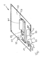
- The figure shows as schematic, perspective view of a preferred embodiment of a passenger service unit (PSU) according to the invention.
- As shown in the figure, a PSU 1 comprises a base plate 10 which is adapted to be mounted in the aircraft interior lining by respective mounting means.
- The base plate 10 comprises two
adjacent openings light 20 and anactivation switch 30 for said reading light is mounted. - The reading
light 20 is shown in a schematic, sectional view. As can be seen, the readinglight 20 comprises alight source 21 and aconvex reflector 22 surrounding partially saidlight source 21. The light source is connected via electrical wiring to the activation switch and a main electrical power source. - Further, a
lid 50 is mounted into a rectangular recess in the base plate 10. Saidlid 50 carries achemical oxygen generator 51 with anignition starter 52 at its first end. The chemical oxygen generator is connected via an oxygen supply line with acontrol unit 53 and a flexible supply line to be connected to an oxygen mask (not shown). - Still further, a
rechargeable battery 55 is mounted to saidlid 50 and electrically connected to thecontrol unit 53 and theignition unit 52. - The
rechargeable battery pack 55 is further electrically connected to aphotovoltaic element 60 which is directly attached to the outside of thereflector 22. Thereflector 22 is semitransparent - By this electrical connection, the
rechargeable battery 55 is periodically charged in times when the readinglight 20 is switched on so that thephotovoltaic element 60 produces an electrical current and supplies this current to therechargeable battery 55. Therechargeable battery 55 has a capacity which is sufficient to activate theignition unit 52 and to supply an electrical voltage at a sufficient level to thecontrol unit 53 during supply of oxygen out of thechemical oxygen generator 51 from start until complete exhaustion of the generator. - A further embodiment of the invention is a method of operating an emergency oxygen device for supply of oxygen to a passenger of an aircraft. Said method comprises the steps of charging a rechargeable battery with electrical current which is energy harvested by an energy harvesting device adjacent to a reflector of a reading light of a passenger service unit comprising the emergency oxygen device and supplying electrical energy out of said rechargeable battery in case of an emergency to start the oxygen supply and/or to control the oxygen flow with a control unit of said emergency oxygen device. The method can be further improved in that the energy is harvested using a Peltier element or a photovoltaic element. In particular, said energy harvesting element can be directly attached to the reflector and light emitted by the light source of the reading light can be directed to said energy harvesting element through a semi transparent section of said reflector.
- Further, an aspect of the invention is the use of an energy harvesting element adjacent or attached to a reflector of a reading light for supplying electrical energy to a rechargeable energy storage device of an emergency oxygen device of a passenger service unit for an aircraft.
Claims (9)
- Passenger service unit for use in an aircraft, comprising- a reading light having a light source and a reflector partially enclosing the light source, and- an emergency oxygen supply device comprising an oxygen source, a starter unit for releasing oxygen flow from said oxygen source to an oxygen mask, a control unit for controlling oxygen flow rate from said oxygen source to said oxygen mask and an electrical energy storage device like a rechargeable battery pack or a condensator, for providing electrical energy to said control unit and/or said starter unit,
Characterized by an energy harvesting unit adjacent to or integrated into said reflector of said reading light wherein said energy harvesting unit is electrically connected to said electrical energy storage device. - PSU according to claim 1,
Wherein said energy harvesting unit is selected from- A Peltier element,- A photovoltaic cell. - PSU according to claim 1 or 2,
Wherein said reflector is at least partly semitransparent and arranged between said light source and said energy harvesting element. - PSU according to any of the preceding claims,
Wherein said energy harvesting element is mounted to said reflector. - PSU according to any of the preceding claims,
Wherein said energy harvesting element is provided as a layer of said reflector. - PSU according to any of the preceding claims,
Wherein said energy harvesting element is a section of said reflector. - PSU according to any of the preceding claims,
wherein said emergency oxygen supply device is not connected to a power supply outside of the PSU. - PSU according to any of the preceding claims,
wherein said oxygen source is an oxygen reservoir comprising a limited amount of oxygen and said energy storage device has a capacity which is sufficient to provide an amount of energy for starting said oxygen supply via said starter unit and for providing electrical energy to said control unit during supply of the whole oxygen contained in said oxygen reservoir. - PSU according to any of the preceding claims,
wherein a plurality of reading lights is provided within the PSU and at least two reading lights comprise an energy harvesting element adjacent to the reflector and said at least two energy harvesting elements are connected to a single energy storage devices.
Priority Applications (3)
| Application Number | Priority Date | Filing Date | Title |
|---|---|---|---|
| EP12151298.2A EP2615030B1 (en) | 2012-01-16 | 2012-01-16 | Passenger service unit with emergency oxygen supply and reading light |
| US13/351,308 US8978644B2 (en) | 2012-01-16 | 2012-01-17 | Passenger service unit with emergency oxygen supply and reading light |
| PCT/EP2013/050743 WO2013107769A1 (en) | 2012-01-16 | 2013-01-16 | Passenger service unit with emergency oxygen supply and reading light |
Applications Claiming Priority (1)
| Application Number | Priority Date | Filing Date | Title |
|---|---|---|---|
| EP12151298.2A EP2615030B1 (en) | 2012-01-16 | 2012-01-16 | Passenger service unit with emergency oxygen supply and reading light |
Publications (2)
| Publication Number | Publication Date |
|---|---|
| EP2615030A1 true EP2615030A1 (en) | 2013-07-17 |
| EP2615030B1 EP2615030B1 (en) | 2015-07-29 |
Family
ID=47594729
Family Applications (1)
| Application Number | Title | Priority Date | Filing Date |
|---|---|---|---|
| EP12151298.2A Not-in-force EP2615030B1 (en) | 2012-01-16 | 2012-01-16 | Passenger service unit with emergency oxygen supply and reading light |
Country Status (3)
| Country | Link |
|---|---|
| US (1) | US8978644B2 (en) |
| EP (1) | EP2615030B1 (en) |
| WO (1) | WO2013107769A1 (en) |
Families Citing this family (6)
| Publication number | Priority date | Publication date | Assignee | Title |
|---|---|---|---|---|
| DE102013013106B4 (en) * | 2013-08-06 | 2023-01-05 | Diehl Aerospace Gmbh | lighting device and vehicle |
| US9487296B2 (en) * | 2013-09-30 | 2016-11-08 | Peco Manufacturing Co., Inc. | Passenger service unit and related systems |
| US10716348B2 (en) | 2016-04-05 | 2020-07-21 | Irma Faye Dozier | Wig making tools and kit |
| CA3040714A1 (en) | 2018-04-18 | 2019-10-18 | Zodiac Aerotechnics | An emergency oxygen system for aircraft with switching device and a method of operating an emergency oxygen system |
| DE102021104928A1 (en) | 2021-03-02 | 2022-09-08 | Airbus Operations Gmbh | Passenger service unit for a passenger cabin of an aircraft or spacecraft |
| EP4279144A1 (en) * | 2022-05-19 | 2023-11-22 | B/E Aerospace Systems GmbH | Aircraft emergency oxygen supply device, aircraft comprising such an emergency oxygen supply device, and method of operating an aircraft emergency oxygen supply device |
Citations (4)
| Publication number | Priority date | Publication date | Assignee | Title |
|---|---|---|---|---|
| US5567230A (en) * | 1995-04-05 | 1996-10-22 | Sinclair; Hugh J. | Air filter for use with aircraft ventilation systems |
| US20040155251A1 (en) | 2003-02-07 | 2004-08-12 | Vladimir Abramov | Peltier cooler integrated with electronic device(s) |
| JP2007036166A (en) | 2005-07-27 | 2007-02-08 | Advanced Material Japan Corp | Long persistence light |
| EP2178118A1 (en) | 2008-10-07 | 2010-04-21 | Intertechnique SA | Light emitting diode with energy recovery system |
Family Cites Families (10)
| Publication number | Priority date | Publication date | Assignee | Title |
|---|---|---|---|---|
| US2358681A (en) * | 1944-01-06 | 1944-09-19 | Electric Storage Battery Co | Charge control system for storage batteries |
| US3023257A (en) * | 1958-05-29 | 1962-02-27 | Minnesota Mining & Mfg | Thermoelectric generator |
| JPH0218857A (en) * | 1988-07-04 | 1990-01-23 | Japan Aviation Electron Ind Ltd | Fluorescent lamp device |
| US5647658A (en) * | 1995-05-11 | 1997-07-15 | Ziadi; Bouchaib | Fiber-optic lighting system |
| US6818818B2 (en) * | 2002-08-13 | 2004-11-16 | Esmond T. Goei | Concentrating solar energy receiver |
| DE10314125B4 (en) * | 2003-03-28 | 2005-02-24 | Carl Zeiss Jena Gmbh | Arrangement for illuminating objects with light of different wavelengths |
| US20060023463A1 (en) * | 2004-07-12 | 2006-02-02 | Goodrich Hella Aerospace Lighting Systems Gmbh | Reading lamp for a vehicle |
| US7597286B2 (en) * | 2005-09-12 | 2009-10-06 | Boeing Company | Simplified power system for a cabin services system for an aircraft |
| TW201138170A (en) * | 2010-04-23 | 2011-11-01 | Inst Nuclear Energy Res Atomic Energy Council | Thermoelectric generating module |
| US8882033B2 (en) * | 2011-02-10 | 2014-11-11 | Zodiac Aerotechnics | Passenger cabin emergency oxygen device |
-
2012
- 2012-01-16 EP EP12151298.2A patent/EP2615030B1/en not_active Not-in-force
- 2012-01-17 US US13/351,308 patent/US8978644B2/en not_active Expired - Fee Related
-
2013
- 2013-01-16 WO PCT/EP2013/050743 patent/WO2013107769A1/en not_active Ceased
Patent Citations (4)
| Publication number | Priority date | Publication date | Assignee | Title |
|---|---|---|---|---|
| US5567230A (en) * | 1995-04-05 | 1996-10-22 | Sinclair; Hugh J. | Air filter for use with aircraft ventilation systems |
| US20040155251A1 (en) | 2003-02-07 | 2004-08-12 | Vladimir Abramov | Peltier cooler integrated with electronic device(s) |
| JP2007036166A (en) | 2005-07-27 | 2007-02-08 | Advanced Material Japan Corp | Long persistence light |
| EP2178118A1 (en) | 2008-10-07 | 2010-04-21 | Intertechnique SA | Light emitting diode with energy recovery system |
Also Published As
| Publication number | Publication date |
|---|---|
| US20130180522A1 (en) | 2013-07-18 |
| US8978644B2 (en) | 2015-03-17 |
| EP2615030B1 (en) | 2015-07-29 |
| WO2013107769A1 (en) | 2013-07-25 |
Similar Documents
| Publication | Publication Date | Title |
|---|---|---|
| EP2615030B1 (en) | Passenger service unit with emergency oxygen supply and reading light | |
| US7550866B2 (en) | Vehicular power distribution system and method | |
| EP1928745B1 (en) | Energy supply system and method for supplying energy to aircraft systems | |
| US9828917B2 (en) | Rapid assistance device for a free turbine engine of an aircraft | |
| JP6159073B2 (en) | Power distribution from multiple power sources in aircraft | |
| CN106457991A (en) | Vehicle having an energy storage means | |
| AU2005254520B2 (en) | System and method for electrical energy switching and control in a vehicle | |
| JP5539541B2 (en) | Battery system for micro hybrid vehicles with high power consumption devices | |
| EP3398818B1 (en) | Voltage supply unit, battery balancing method | |
| US20130210329A1 (en) | Self-sufficient monument in the aircraft pressure cabin having a decentralized operating resource supply and efficient energy conversion | |
| US20130114779A1 (en) | Apparatus for charging emergency battery using thermoelectric generation device in nuclear power plant | |
| US10099789B2 (en) | Self sufficient galley system, method for operating electrical galley devices, and aircraft having such a galley system | |
| WO2008059884A1 (en) | Controller | |
| US20210107379A1 (en) | Power Battery Heating System and Method Using Solar Sunroof Energy | |
| JP2008526620A (en) | Energy buffer device for aircraft | |
| CN118323458B (en) | Aircraft energy control method and system | |
| EP2178118B1 (en) | Light emitting diode with energy recovery system | |
| US20110299273A1 (en) | Lighting device with wind generator | |
| US8188665B2 (en) | Light emitting diode with energy recovery system | |
| KR20260028358A (en) | Auxiliary battery system for ships | |
| JP4802793B2 (en) | Dual power supply vehicle power supply device | |
| CN113752969B (en) | Vehicle power supply system and vehicle comprising same | |
| KR20200075061A (en) | Integrated motor controller for electric vehicle | |
| KR20210020453A (en) | Ship | |
| WO2019145529A1 (en) | Avalanche airbag system, carrying device comprising an avalanche airbag system, and method for operating an avalanche airbag system |
Legal Events
| Date | Code | Title | Description |
|---|---|---|---|
| PUAI | Public reference made under article 153(3) epc to a published international application that has entered the european phase |
Free format text: ORIGINAL CODE: 0009012 |
|
| AK | Designated contracting states |
Kind code of ref document: A1 Designated state(s): AL AT BE BG CH CY CZ DE DK EE ES FI FR GB GR HR HU IE IS IT LI LT LU LV MC MK MT NL NO PL PT RO RS SE SI SK SM TR |
|
| AX | Request for extension of the european patent |
Extension state: BA ME |
|
| 17P | Request for examination filed |
Effective date: 20140117 |
|
| RBV | Designated contracting states (corrected) |
Designated state(s): AL AT BE BG CH CY CZ DE DK EE ES FI FR GB GR HR HU IE IS IT LI LT LU LV MC MK MT NL NO PL PT RO RS SE SI SK SM TR |
|
| RAP1 | Party data changed (applicant data changed or rights of an application transferred) |
Owner name: ZODIAC AEROTECHNICS |
|
| GRAP | Despatch of communication of intention to grant a patent |
Free format text: ORIGINAL CODE: EPIDOSNIGR1 |
|
| INTG | Intention to grant announced |
Effective date: 20150212 |
|
| GRAS | Grant fee paid |
Free format text: ORIGINAL CODE: EPIDOSNIGR3 |
|
| GRAA | (expected) grant |
Free format text: ORIGINAL CODE: 0009210 |
|
| AK | Designated contracting states |
Kind code of ref document: B1 Designated state(s): AL AT BE BG CH CY CZ DE DK EE ES FI FR GB GR HR HU IE IS IT LI LT LU LV MC MK MT NL NO PL PT RO RS SE SI SK SM TR |
|
| REG | Reference to a national code |
Ref country code: GB Ref legal event code: FG4D |
|
| REG | Reference to a national code |
Ref country code: CH Ref legal event code: EP |
|
| REG | Reference to a national code |
Ref country code: AT Ref legal event code: REF Ref document number: 739045 Country of ref document: AT Kind code of ref document: T Effective date: 20150815 |
|
| REG | Reference to a national code |
Ref country code: IE Ref legal event code: FG4D |
|
| REG | Reference to a national code |
Ref country code: DE Ref legal event code: R096 Ref document number: 602012009052 Country of ref document: DE |
|
| REG | Reference to a national code |
Ref country code: AT Ref legal event code: MK05 Ref document number: 739045 Country of ref document: AT Kind code of ref document: T Effective date: 20150729 |
|
| REG | Reference to a national code |
Ref country code: LT Ref legal event code: MG4D |
|
| REG | Reference to a national code |
Ref country code: NL Ref legal event code: MP Effective date: 20150729 |
|
| REG | Reference to a national code |
Ref country code: FR Ref legal event code: PLFP Year of fee payment: 5 |
|
| PG25 | Lapsed in a contracting state [announced via postgrant information from national office to epo] |
Ref country code: LT Free format text: LAPSE BECAUSE OF FAILURE TO SUBMIT A TRANSLATION OF THE DESCRIPTION OR TO PAY THE FEE WITHIN THE PRESCRIBED TIME-LIMIT Effective date: 20150729 Ref country code: FI Free format text: LAPSE BECAUSE OF FAILURE TO SUBMIT A TRANSLATION OF THE DESCRIPTION OR TO PAY THE FEE WITHIN THE PRESCRIBED TIME-LIMIT Effective date: 20150729 Ref country code: GR Free format text: LAPSE BECAUSE OF FAILURE TO SUBMIT A TRANSLATION OF THE DESCRIPTION OR TO PAY THE FEE WITHIN THE PRESCRIBED TIME-LIMIT Effective date: 20151030 Ref country code: NO Free format text: LAPSE BECAUSE OF FAILURE TO SUBMIT A TRANSLATION OF THE DESCRIPTION OR TO PAY THE FEE WITHIN THE PRESCRIBED TIME-LIMIT Effective date: 20151029 Ref country code: LV Free format text: LAPSE BECAUSE OF FAILURE TO SUBMIT A TRANSLATION OF THE DESCRIPTION OR TO PAY THE FEE WITHIN THE PRESCRIBED TIME-LIMIT Effective date: 20150729 |
|
| PG25 | Lapsed in a contracting state [announced via postgrant information from national office to epo] |
Ref country code: PL Free format text: LAPSE BECAUSE OF FAILURE TO SUBMIT A TRANSLATION OF THE DESCRIPTION OR TO PAY THE FEE WITHIN THE PRESCRIBED TIME-LIMIT Effective date: 20150729 Ref country code: ES Free format text: LAPSE BECAUSE OF FAILURE TO SUBMIT A TRANSLATION OF THE DESCRIPTION OR TO PAY THE FEE WITHIN THE PRESCRIBED TIME-LIMIT Effective date: 20150729 Ref country code: PT Free format text: LAPSE BECAUSE OF FAILURE TO SUBMIT A TRANSLATION OF THE DESCRIPTION OR TO PAY THE FEE WITHIN THE PRESCRIBED TIME-LIMIT Effective date: 20151130 Ref country code: RS Free format text: LAPSE BECAUSE OF FAILURE TO SUBMIT A TRANSLATION OF THE DESCRIPTION OR TO PAY THE FEE WITHIN THE PRESCRIBED TIME-LIMIT Effective date: 20150729 Ref country code: HR Free format text: LAPSE BECAUSE OF FAILURE TO SUBMIT A TRANSLATION OF THE DESCRIPTION OR TO PAY THE FEE WITHIN THE PRESCRIBED TIME-LIMIT Effective date: 20150729 Ref country code: AT Free format text: LAPSE BECAUSE OF FAILURE TO SUBMIT A TRANSLATION OF THE DESCRIPTION OR TO PAY THE FEE WITHIN THE PRESCRIBED TIME-LIMIT Effective date: 20150729 Ref country code: SE Free format text: LAPSE BECAUSE OF FAILURE TO SUBMIT A TRANSLATION OF THE DESCRIPTION OR TO PAY THE FEE WITHIN THE PRESCRIBED TIME-LIMIT Effective date: 20150729 Ref country code: IS Free format text: LAPSE BECAUSE OF FAILURE TO SUBMIT A TRANSLATION OF THE DESCRIPTION OR TO PAY THE FEE WITHIN THE PRESCRIBED TIME-LIMIT Effective date: 20151129 |
|
| PG25 | Lapsed in a contracting state [announced via postgrant information from national office to epo] |
Ref country code: NL Free format text: LAPSE BECAUSE OF FAILURE TO SUBMIT A TRANSLATION OF THE DESCRIPTION OR TO PAY THE FEE WITHIN THE PRESCRIBED TIME-LIMIT Effective date: 20150729 |
|
| PG25 | Lapsed in a contracting state [announced via postgrant information from national office to epo] |
Ref country code: DK Free format text: LAPSE BECAUSE OF FAILURE TO SUBMIT A TRANSLATION OF THE DESCRIPTION OR TO PAY THE FEE WITHIN THE PRESCRIBED TIME-LIMIT Effective date: 20150729 Ref country code: EE Free format text: LAPSE BECAUSE OF FAILURE TO SUBMIT A TRANSLATION OF THE DESCRIPTION OR TO PAY THE FEE WITHIN THE PRESCRIBED TIME-LIMIT Effective date: 20150729 Ref country code: SK Free format text: LAPSE BECAUSE OF FAILURE TO SUBMIT A TRANSLATION OF THE DESCRIPTION OR TO PAY THE FEE WITHIN THE PRESCRIBED TIME-LIMIT Effective date: 20150729 Ref country code: CZ Free format text: LAPSE BECAUSE OF FAILURE TO SUBMIT A TRANSLATION OF THE DESCRIPTION OR TO PAY THE FEE WITHIN THE PRESCRIBED TIME-LIMIT Effective date: 20150729 Ref country code: IT Free format text: LAPSE BECAUSE OF FAILURE TO SUBMIT A TRANSLATION OF THE DESCRIPTION OR TO PAY THE FEE WITHIN THE PRESCRIBED TIME-LIMIT Effective date: 20150729 |
|
| PGFP | Annual fee paid to national office [announced via postgrant information from national office to epo] |
Ref country code: DE Payment date: 20160203 Year of fee payment: 5 |
|
| REG | Reference to a national code |
Ref country code: DE Ref legal event code: R097 Ref document number: 602012009052 Country of ref document: DE |
|
| PG25 | Lapsed in a contracting state [announced via postgrant information from national office to epo] |
Ref country code: RO Free format text: LAPSE BECAUSE OF FAILURE TO SUBMIT A TRANSLATION OF THE DESCRIPTION OR TO PAY THE FEE WITHIN THE PRESCRIBED TIME-LIMIT Effective date: 20150729 Ref country code: BE Free format text: LAPSE BECAUSE OF NON-PAYMENT OF DUE FEES Effective date: 20160131 |
|
| PGFP | Annual fee paid to national office [announced via postgrant information from national office to epo] |
Ref country code: FR Payment date: 20160128 Year of fee payment: 5 |
|
| PLBE | No opposition filed within time limit |
Free format text: ORIGINAL CODE: 0009261 |
|
| STAA | Information on the status of an ep patent application or granted ep patent |
Free format text: STATUS: NO OPPOSITION FILED WITHIN TIME LIMIT |
|
| 26N | No opposition filed |
Effective date: 20160502 |
|
| PG25 | Lapsed in a contracting state [announced via postgrant information from national office to epo] |
Ref country code: SI Free format text: LAPSE BECAUSE OF FAILURE TO SUBMIT A TRANSLATION OF THE DESCRIPTION OR TO PAY THE FEE WITHIN THE PRESCRIBED TIME-LIMIT Effective date: 20150729 Ref country code: LU Free format text: LAPSE BECAUSE OF FAILURE TO SUBMIT A TRANSLATION OF THE DESCRIPTION OR TO PAY THE FEE WITHIN THE PRESCRIBED TIME-LIMIT Effective date: 20160116 |
|
| REG | Reference to a national code |
Ref country code: CH Ref legal event code: PL |
|
| GBPC | Gb: european patent ceased through non-payment of renewal fee |
Effective date: 20160116 |
|
| PG25 | Lapsed in a contracting state [announced via postgrant information from national office to epo] |
Ref country code: MC Free format text: LAPSE BECAUSE OF FAILURE TO SUBMIT A TRANSLATION OF THE DESCRIPTION OR TO PAY THE FEE WITHIN THE PRESCRIBED TIME-LIMIT Effective date: 20150729 |
|
| PG25 | Lapsed in a contracting state [announced via postgrant information from national office to epo] |
Ref country code: CH Free format text: LAPSE BECAUSE OF NON-PAYMENT OF DUE FEES Effective date: 20160131 Ref country code: GB Free format text: LAPSE BECAUSE OF NON-PAYMENT OF DUE FEES Effective date: 20160116 Ref country code: LI Free format text: LAPSE BECAUSE OF NON-PAYMENT OF DUE FEES Effective date: 20160131 |
|
| REG | Reference to a national code |
Ref country code: IE Ref legal event code: MM4A |
|
| PG25 | Lapsed in a contracting state [announced via postgrant information from national office to epo] |
Ref country code: BE Free format text: LAPSE BECAUSE OF FAILURE TO SUBMIT A TRANSLATION OF THE DESCRIPTION OR TO PAY THE FEE WITHIN THE PRESCRIBED TIME-LIMIT Effective date: 20150729 |
|
| PG25 | Lapsed in a contracting state [announced via postgrant information from national office to epo] |
Ref country code: IE Free format text: LAPSE BECAUSE OF NON-PAYMENT OF DUE FEES Effective date: 20160116 |
|
| REG | Reference to a national code |
Ref country code: DE Ref legal event code: R119 Ref document number: 602012009052 Country of ref document: DE |
|
| PG25 | Lapsed in a contracting state [announced via postgrant information from national office to epo] |
Ref country code: MT Free format text: LAPSE BECAUSE OF FAILURE TO SUBMIT A TRANSLATION OF THE DESCRIPTION OR TO PAY THE FEE WITHIN THE PRESCRIBED TIME-LIMIT Effective date: 20150729 |
|
| REG | Reference to a national code |
Ref country code: FR Ref legal event code: ST Effective date: 20170929 |
|
| PG25 | Lapsed in a contracting state [announced via postgrant information from national office to epo] |
Ref country code: FR Free format text: LAPSE BECAUSE OF NON-PAYMENT OF DUE FEES Effective date: 20170131 |
|
| PG25 | Lapsed in a contracting state [announced via postgrant information from national office to epo] |
Ref country code: DE Free format text: LAPSE BECAUSE OF NON-PAYMENT OF DUE FEES Effective date: 20170801 |
|
| PG25 | Lapsed in a contracting state [announced via postgrant information from national office to epo] |
Ref country code: HU Free format text: LAPSE BECAUSE OF FAILURE TO SUBMIT A TRANSLATION OF THE DESCRIPTION OR TO PAY THE FEE WITHIN THE PRESCRIBED TIME-LIMIT; INVALID AB INITIO Effective date: 20120116 Ref country code: SM Free format text: LAPSE BECAUSE OF FAILURE TO SUBMIT A TRANSLATION OF THE DESCRIPTION OR TO PAY THE FEE WITHIN THE PRESCRIBED TIME-LIMIT Effective date: 20150729 Ref country code: CY Free format text: LAPSE BECAUSE OF FAILURE TO SUBMIT A TRANSLATION OF THE DESCRIPTION OR TO PAY THE FEE WITHIN THE PRESCRIBED TIME-LIMIT Effective date: 20150729 |
|
| PG25 | Lapsed in a contracting state [announced via postgrant information from national office to epo] |
Ref country code: MK Free format text: LAPSE BECAUSE OF FAILURE TO SUBMIT A TRANSLATION OF THE DESCRIPTION OR TO PAY THE FEE WITHIN THE PRESCRIBED TIME-LIMIT Effective date: 20150729 Ref country code: MT Free format text: LAPSE BECAUSE OF FAILURE TO SUBMIT A TRANSLATION OF THE DESCRIPTION OR TO PAY THE FEE WITHIN THE PRESCRIBED TIME-LIMIT Effective date: 20160131 Ref country code: TR Free format text: LAPSE BECAUSE OF FAILURE TO SUBMIT A TRANSLATION OF THE DESCRIPTION OR TO PAY THE FEE WITHIN THE PRESCRIBED TIME-LIMIT Effective date: 20150729 |
|
| PG25 | Lapsed in a contracting state [announced via postgrant information from national office to epo] |
Ref country code: BG Free format text: LAPSE BECAUSE OF FAILURE TO SUBMIT A TRANSLATION OF THE DESCRIPTION OR TO PAY THE FEE WITHIN THE PRESCRIBED TIME-LIMIT Effective date: 20150729 |
|
| PG25 | Lapsed in a contracting state [announced via postgrant information from national office to epo] |
Ref country code: AL Free format text: LAPSE BECAUSE OF FAILURE TO SUBMIT A TRANSLATION OF THE DESCRIPTION OR TO PAY THE FEE WITHIN THE PRESCRIBED TIME-LIMIT Effective date: 20150729 |