EP2614879A1 - Dehydrating device - Google Patents
Dehydrating device Download PDFInfo
- Publication number
- EP2614879A1 EP2614879A1 EP11823470.7A EP11823470A EP2614879A1 EP 2614879 A1 EP2614879 A1 EP 2614879A1 EP 11823470 A EP11823470 A EP 11823470A EP 2614879 A1 EP2614879 A1 EP 2614879A1
- Authority
- EP
- European Patent Office
- Prior art keywords
- tank
- line
- treated fluid
- units
- fluid
- Prior art date
- Legal status (The legal status is an assumption and is not a legal conclusion. Google has not performed a legal analysis and makes no representation as to the accuracy of the status listed.)
- Withdrawn
Links
Images






Classifications
-
- B—PERFORMING OPERATIONS; TRANSPORTING
- B01—PHYSICAL OR CHEMICAL PROCESSES OR APPARATUS IN GENERAL
- B01D—SEPARATION
- B01D61/00—Processes of separation using semi-permeable membranes, e.g. dialysis, osmosis or ultrafiltration; Apparatus, accessories or auxiliary operations specially adapted therefor
- B01D61/58—Multistep processes
-
- B—PERFORMING OPERATIONS; TRANSPORTING
- B01—PHYSICAL OR CHEMICAL PROCESSES OR APPARATUS IN GENERAL
- B01D—SEPARATION
- B01D61/00—Processes of separation using semi-permeable membranes, e.g. dialysis, osmosis or ultrafiltration; Apparatus, accessories or auxiliary operations specially adapted therefor
- B01D61/36—Pervaporation; Membrane distillation; Liquid permeation
- B01D61/362—Pervaporation
-
- C—CHEMISTRY; METALLURGY
- C07—ORGANIC CHEMISTRY
- C07C—ACYCLIC OR CARBOCYCLIC COMPOUNDS
- C07C29/00—Preparation of compounds having hydroxy or O-metal groups bound to a carbon atom not belonging to a six-membered aromatic ring
- C07C29/74—Separation; Purification; Use of additives, e.g. for stabilisation
- C07C29/76—Separation; Purification; Use of additives, e.g. for stabilisation by physical treatment
-
- B—PERFORMING OPERATIONS; TRANSPORTING
- B01—PHYSICAL OR CHEMICAL PROCESSES OR APPARATUS IN GENERAL
- B01D—SEPARATION
- B01D2313/00—Details relating to membrane modules or apparatus
- B01D2313/08—Flow guidance means within the module or the apparatus
- B01D2313/083—Bypass routes
-
- B—PERFORMING OPERATIONS; TRANSPORTING
- B01—PHYSICAL OR CHEMICAL PROCESSES OR APPARATUS IN GENERAL
- B01D—SEPARATION
- B01D2315/00—Details relating to the membrane module operation
- B01D2315/04—Reciprocation, oscillation or vibration
-
- B—PERFORMING OPERATIONS; TRANSPORTING
- B01—PHYSICAL OR CHEMICAL PROCESSES OR APPARATUS IN GENERAL
- B01D—SEPARATION
- B01D2317/00—Membrane module arrangements within a plant or an apparatus
- B01D2317/02—Elements in series
-
- B—PERFORMING OPERATIONS; TRANSPORTING
- B01—PHYSICAL OR CHEMICAL PROCESSES OR APPARATUS IN GENERAL
- B01D—SEPARATION
- B01D2317/00—Membrane module arrangements within a plant or an apparatus
- B01D2317/02—Elements in series
- B01D2317/022—Reject series
-
- B—PERFORMING OPERATIONS; TRANSPORTING
- B01—PHYSICAL OR CHEMICAL PROCESSES OR APPARATUS IN GENERAL
- B01D—SEPARATION
- B01D2317/00—Membrane module arrangements within a plant or an apparatus
- B01D2317/04—Elements in parallel
Definitions
- the present invention relates to a dehydrator for dehydrating a mixture (treated fluid) of water with ethanol which forms an azeotropic composition with water.
- ethanol has attracted attention as a fuel source alternative to petroleum fuels.
- Known conventional dehydration methods include a method for separating water from the treated fluid by the pervaporation method (penetrative vaporization (PV) method) using a water separation membrane (see, for example, Patent Literature 1).
- PV pervaporation
- Patent Literature 1 a plurality of water separation membranes is arranged so that the water separation membranes are arranged in series in the inside of a shell part.
- the treated fluid containing water passes through the serially arranged water separation membranes one after another. In this manner, water is separated from the treated fluid.
- Fig. 7 is a schematic diagram which illustrates the entire conventional dehydrator.
- a dehydrator 31 includes a first tank 32, to which the treated fluid (a crude ethanol aqueous solution) is supplied, a second tank 33, into which dehydrated product ethanol flows, a line 34 for allowing the treated fluid to flow from the first tank 2 to the second tank 3, a plurality of water separation membrane units 35A through 35J provided between the first tank 2 and the second tank 3, and a third tank 36, into which the water separated from the treated fluid flows.
- the treated fluid a crude ethanol aqueous solution
- the plurality of water separation membrane units 35A through 35J is connected in series.
- Each of heat exchangers 37A through 37J is provided among the water separation membrane units 35A through 35J.
- each of bypass lines 38A through 38J for bypassing the water separation membrane units 35A through 35J is provided.
- a first problem which arises in the configuration illustrated in Fig. 7 and the conventional configuration discussed by Patent Literature 1, may arise because the water separation membrane units are arranged in series in this configuration. For example, if water separation membrane units are arranged in series and if any malfunction has occurred in a water separation membrane unit on an upstream side out of the water separation membrane units, the malfunction may affect the water separation membrane units on a downstream side. More specifically, if any malfunction has occurred in a water separation membrane unit on the upstream side, it becomes necessary to stop the entire dehydrator and to execute a maintenance operation. Accordingly, a problem may arise such that the dehydrator cannot be stably operated. In addition, in this case, although the operation of the dehydrator can be continued by using the bypass lines, the treated fluid may not be dehydrated until a predetermined concentration is achieved because the number of times the treated fluid passes through the water separation membrane units is reduced.
- Fig. 8 illustrates a ratio of quantity of permeated water to the quantity of permeation of a matter (containing water and ethanol) that has permeated through water separation membranes.
- the ratio of quantity of permeated water is about 1 at the velocity of flow of approximately 0.6 m/s.
- the ratio of quantity of permeated water to the quantity of matter permeated through the water separation membranes becomes lower as the velocity of flow of the treated fluid becomes lower.
- the ratio of permeated water to the matter permeated through the water separation membranes becomes low. As a result, the water separation performance may degrade.
- concentration polarization is a phenomenon that may occur in the vicinity of water separation membranes, in which a dissolved matter (water in the example illustrated in Fig. 8 ) that does not permeate through water separation membranes produce a gradient of concentration in the direction perpendicular to the water separation membrane.
- Figs. 9A and 9B illustrate a case where the concentration gradient is produced and another case where the concentration gradient is not produced. More specifically, Fig. 9A illustrates a case where the velocity of flow of the treated fluid is low. Fig. 9B illustrates a case where the velocity of flow of the treated fluid is high. As illustrated in a chart (1) of Fig. 9A , if the velocity of flow of the treated fluid is low, the concentration of water becomes lower as the distance to the water separation membrane becomes smaller while the concentration of water becomes higher as the distance to the water separation membrane in the direction perpendicular to the water separation membrane (in the direction of the cross section) becomes greater.
- the configuration that uses water separation membranes requires certain measures for securely dehydrating the treated fluid well enough to reach a predetermined concentration.
- the present invention is devised to solve the above-described problems.
- the object of the present invention is to provide a dehydrator which can be safely operated if any malfunction has occurred to a water separation membrane unit and which is capable of securely dehydrating the treated fluid well enough to reach the predetermined concentration.
- the treated fluid is configured to reciprocate between the first tank and the second tank and is configured to pass through the plurality of membrane container units for a plurality of times.
- the dehydrator further includes a first line configured to allow the treated fluid to reciprocate between the first tank and the second tank.
- the plurality of membrane container units is arranged on the first line in parallel to one another and the treated fluid is configured, after all the treated fluid has flowed from the first tank to the second tank via the plurality of membrane container units provided on the first line and no treated fluid remains in the first tank, to flow from the second tank to the first tank via the plurality of membrane container units provided on the first line.
- the dehydrator further includes the first line configured to allow the treated fluid to flow from the first tank to the second tank, and a second line configured to allow the treated fluid to flow from the second tank to the first tank.
- the plurality of membrane container units is arranged in parallel to one another and the treated fluid is configured, after all the treated fluid has flowed from the first tank to the second tank via the plurality of membrane container units provided on the first line and no treated fluid remains in the first tank, to flow from the second tank to the first tank via the second line.
- the dehydrator further includes the first line configured to allow the treated fluid to flow from the first tank to the second tank, and the second line configured to allow the treated fluid to flow from the second tank to the first tank.
- the plurality of membrane container units is divided into a first unit group including units provided on the first line and in parallel to one another and a second unit group including units provided on the second line and in parallel to one another, and the treated fluid is configured, after all the treated fluid has flowed from the first tank to the second tank via the first unit group provided on the first line and no treated fluid remains in the first tank, to flow from the second tank to the first tank via the second unit group provided on the second line.
- the dehydrator further includes the first line configured to allow the treated fluid to flow from the first tank to the second tank, the second line configured to allow the treated fluid to flow from the second tank to the first tank, and at least one intermediate tank provided between the first tank and the second tank and connected to both the first line and the second line.
- the first line is divided into a plurality of first fluid lines provided across the intermediate tank and the second line is divided into a plurality of second fluid lines provided across the intermediate tank
- the plurality of membrane container units is divided into unit groups including as many units as a total number of the first fluid line and the second fluid line and units included in the unit group of the plurality of membrane container units are provided in parallel to one another on each of the first fluid line and the second fluid line
- the treated fluid is configured to flow from the first tank to the second tank successively via the units included in the unit group provided on the first line and the intermediate tank and is configured to flow from the second tank to the first tank successively via the units included in the unit group provided on the second line and the intermediate tank
- the second line includes at least one bypass line
- the bypass line is configured to bypass one or more units of the unit group provided on the second line, to allow the treated fluid to return to the intermediate tank or the first tank.
- the dehydrator of an aspect of the present invention because a plurality of membrane container units is provided in parallel to one another, if any malfunction has occurred to any water separation membrane unit, the maintenance and the replacement can be carried out only for the water separation membrane unit to which the malfunction has occurred without stopping the entire dehydrator. Accordingly, it is enabled to stably operate the dehydrator.
- the treated fluid can be securely dehydrated well enough to reach a predetermined concentration by allowing the treated fluid to reciprocate between the first tank and the second tank and by allowing the treated fluid to repeatedly pass through the membrane container units.
- the second line includes at least one bypass line and the bypass line is configured to bypass one or more units included in the unit group provided on the second line to allow the treated fluid to return to the intermediate tank or the first tank. Accordingly, the number of times the treated fluid is to pass through the membrane container units can be appropriately changed. As a result, the concentration of the treated fluid can be finely adjusted.
- Fig. 1 is a schematic diagram illustrating the entire dehydrator according to the present exemplary embodiment.
- the dehydrator 1 is configured to dehydrate a crude ethanol aqueous solution used as treated fluid.
- the inventors assume approximately 91 wt % of the concentration of ethanol for the concentration of the crude ethanol aqueous solution.
- the dehydrator 1 is configured to treat and purify crude ethanol containing ethanol as an organic component to finally produce product ethanol (absolute ethanol) whose ethanol concentration is in the range of 99.5 to 99.8 wt %.
- the dehydrator 1 includes a first tank 2, to which treated fluid (a crude ethanol aqueous solution) is supplied, a second tank 3, into which the dehydrated product ethanol flows, a first line 41 for allowing the treated fluid to reciprocate between the first tank 2 and the second tank 3, a plurality of (ten in the present exemplary embodiment) water separation membrane units 101 through 110 provided to the first line 41, a third tank 4, into which water separated from the treated fluid flows, and a control unit 5 configured to control the operation of the entire dehydrator 1.
- treated fluid a crude ethanol aqueous solution
- second tank 3 into which the dehydrated product ethanol flows
- a first line 41 for allowing the treated fluid to reciprocate between the first tank 2 and the second tank 3
- a plurality of (ten in the present exemplary embodiment) water separation membrane units 101 through 110 provided to the first line 41
- a third tank 4 into which water separated from the treated fluid flows
- a control unit 5 configured to control the operation of the entire dehydrator 1.
- the first tank 2 is provided with a first ethanol concentration meter 2a.
- the second tank 3 is provided with a second ethanol concentration meter 3a.
- the first ethanol concentration meter 2a and the second ethanol concentration meter 3a are connected to the control unit 5. Detection signals are transmitted from the first ethanol concentration meter 2a and the second ethanol concentration meter 3a to the control unit 5.
- the first line 41 is provided with a first pump 61, which is provided at a location close to the first tank 2, and a second pump 62, which is provided at a location close to the second tank 3.
- the first pump 61 and the second pump 62 are connected to the control unit 5.
- the first pump 61 is configured to pump the treated fluid stored in the first tank 2 into the second tank 3 under control of the control unit 5.
- the second pump 62 also is configured to pump the treated fluid stored in the second tank 3 into the first tank 2 under control of the control unit 5.
- a plurality of water separation membrane units 101 through 110 is provided on the first line 41 in parallel to one another.
- First open-close valves 201 through 210 are provided on the side of the first tank 2 of the water separation membrane units 101 through 110.
- second open-close valves 301 through 310 are provided on the side of the second tank 3 of the water separation membrane units 101 through 110.
- the first open-close valves 201 through 210 and the second open-close valves 301 through 310 are connected to the control unit 5 and are configured to open and close under control of the control unit 5.
- Each of the water separation membrane units 101 through 110 is provided with a membrane container (not illustrated), which will be described below, and is configured to separate water by the pervaporation method in which the supply side is a liquid phase and the permeation side is a gas phase.
- a membrane container (not illustrated), which will be described below, and is configured to separate water by the pervaporation method in which the supply side is a liquid phase and the permeation side is a gas phase.
- a flow path for the treated fluid is referred to as the "supply side” and the outside of the membrane container is referred to as the "permeation side".
- the membrane container is constituted by a combination of a plurality of tubular-type water separation membranes or a monolith-type water separation membrane and has a columnar shape.
- an inorganic porous membrane in which holes on the order of nanometers or smaller are controlled precisely can be used.
- the porous membrane having fine holes achieves a molecule sieving effect of allowing small-molecule gases to pass through and exclude large-molecule gases, and exhibits a behavior of activation diffusion in which the permeation factor thereof increases with the increase in temperature.
- a porous membrane having fine holes a carbon membrane, a silica membrane, and a zeolite membrane can be mentioned.
- the inorganic water separating membrane described in Japanese Patent No. 2808479 can also be applied.
- the inorganic water separating membrane described in Japanese Patent No. 2808479 is an acid-resistant composite separation membrane obtained by carrying silica gel obtained through hydrolysis of alkoxysilane containing an ethoxy group or methoxy group in the fine holes of an inorganic porous body.
- a porous base member on which the inorganic water separation membrane is supported a base member of a ceramic such as alumina, silica, zirconia, or titania is usually used, and a preferable base member is a tubular base member having multiple flow paths (inner tubes) which extend in the longitudinal direction and each of which have a circular cross-section.
- the inorganic water separation membrane is formed in a way to cover inner walls of such inner tubes.
- an organic membrane such as a polyvinyl alcohol membrane, a polyimide membrane or a polyamide membrane can be used as the water separation membrane.
- an organic membrane such as a polyvinyl alcohol membrane, a polyimide membrane or a polyamide membrane
- the material and the size of the membrane container and the diameter, the quantity, and the like of the flow paths can be selected by a person having ordinary skill in the art according to their purpose of use.
- the dehydration treatment by the membrane container is carried out by using a decompression device (not illustrated).
- a decompression device By decompressing the permeation side of the membrane container by using the decompression device, the water contained in the treated fluid that passes through vacuum device the flow path of the membrane container becomes steam.
- the steam is drawn out to the permeation side.
- the water separation membrane units 101 through 110 are respectively connected to the third tank 4 via the steam valves 401 through 410.
- the steam drawn out by each of the water separation membrane units 101 through 110 flows into the third tank 4.
- a first heat exchanger 71 is provided between the first pump 61 and the plurality of water separation membrane units 101 through 110.
- a second heat exchanger 72 is provided between the second pump 62 and the plurality of water separation membrane units 101 through 110. The first heat exchanger 71 and the second heat exchanger 72 apply heat to raise the temperature of the treated fluid that flows into the water separation membrane units 101 through 110 to prevent the temperature of the treated fluid from dropping.
- a first bypass tube 81 for bypassing the first pump 61 and the first heat exchanger 71 is provided on the first line 41. Both ends of the first bypass tube 81 are connected to the first line 41 via a branch valve (not illustrated).
- a second bypass tube 82 for bypassing the second pump 62 and the second heat exchanger 72 is provided on the first line 41. Both ends of the second bypass tube 82 are connected to the first line 41 via a branch valve (not illustrated).
- the branch valve is connected to the control unit 5 and is configured to open and close under control of the control unit 5.
- the water separation membrane units 101 through 110 are provided with detectors 101a through 110a configured to detect malfunction occurring on the membrane container, respectively.
- the detectors 101a through 110a are configured to continuously monitor the state of the membrane containers and can carry out on-line detection of malfunction. For example, if the quantity of permeation is decreased by clogging, the detectors 101a through 110a detect that the decrease in outlet temperature on the supply side is small. Also, if the quantity of permeation is increased by a malfunction occurring in the membrane container, the detectors 101a through 110a can detect that the decrease in temperature on the permeation side is large. Furthermore, the detectors 101a through 110a can detect that the outlet concentration on the supply side has been changed due to the change in the quantity of permeation.
- the detectors 101a through 110a are connected to the control unit 5 and are configured to transmit detection signals to the control unit 5.
- the control unit 5 executes control for closing both the first open-close valves 201 through 210 and the second open-close valves 301 through 310 corresponding to the water separation membrane unit to which the malfunction has occurred, among the water separation membrane units 101 through 110.
- the treated fluid (a crude ethanol aqueous solution) is supplied to the first tank 2.
- the treated fluid is intermittently supplied and the supply of the treated fluid is stopped when the first tank 2 is filled with the treated fluid.
- the control unit 5 controls the branch valve provided between the first line 41 and the first bypass tube 81 to allow the treated fluid to flow into the first line 41.
- the first pump 61 pumps the treated fluid from the first tank 2 to the second tank 3.
- the treated fluid that flows through the first line 41 is heated by the first heat exchanger 71 and is allowed to flow into the plurality of water separation membrane units 101 through 110 provided in parallel to one another.
- the control unit 5 controls the branch valve provided between the first line 41 and the second bypass tube 82 to allow the treated fluid to flow into the second bypass tube 82.
- the treated fluid that has passed through the second bypass tube 82 flows into the second tank 3.
- the control unit 5 receives a concentration measured by the second ethanol concentration meter 3a of the second tank 3. If the concentration measured by the second ethanol concentration meter 3a has not reached a predetermined concentration yet, then the control unit 5 executes control for allowing the treated fluid to flow from the second tank 3 to the first tank 2 in the following manner.
- the control unit 5 controls the branch valve provided between the first line 41 and the second bypass line 82 to allow the treated fluid to flow into the first line 41. Consequently, the second pump 62 pumps the treated fluid from the second tank 3 to the first tank 2.
- the treated fluid that flows through the first line 41 is heated by the second heat exchanger 72 and is allowed to flow into the plurality of water separation membrane units 101 through 110 provided in parallel to one another.
- the steam drawn out by each of the water separation membrane units 101 through 110 during the above-described operation flows into the third tank 4.
- the control unit 5 controls the branch valve provided between the first line 41 and the first bypass tube 81 to allow the treated fluid to flow into the first bypass tube 81.
- the treated fluid that has passed through the first bypass tube 81 flows into the first tank 2.
- the control unit 5 receives a concentration measured by the first ethanol concentration meter 2a of the first tank 2.
- control unit 5 detects whether the concentration measured by the first ethanol concentration meter 2a has reached the predetermined concentration. If it is detected that the concentration has not reached the predetermined concentration yet, then the control unit 5 executes control for allowing the treated fluid to flow from the first tank 2 into the second tank 3 again. The control unit 5 executes the operation described above until the concentration of the treated fluid reaches the predetermined concentration. Then, the treated fluid whose concentration has reached the predetermined concentration is finally recovered from the second tank 3 as product ethanol.
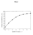
- Fig. 2 is a diagram illustrating a trial calculation of the transition of a concentration of ethanol obtained by dehydrating a crude ethanol aqueous solution by using the dehydrator 1 according to the present exemplary embodiment.
- the "number of stages" taken on the horizontal axis of the example illustrated in Fig. 2 corresponds to the number of times the treated fluid has passed through the plurality of water separation membrane units 101 through 110.
- the number of stages of 1 refers to the timing at which the treated fluid has flowed from the first tank 2 to the second tank 3 once and the number of stages of 2 refers to the timing at which the treated fluid has flowed back from the second tank 3 and again into the first tank 2.
- the dehydrator 1 of the present exemplary embodiment it can be known that the ethanol concentration is increased every time the treated fluid passes through the plurality of water separation membrane units 101 through 110 and the ethanol concentration approaches the predetermined concentration of the product ethanol.
- the plurality of water separation membrane units 101 through 110 is provided on the first line 41 in parallel to one another. Accordingly, if any malfunction has occurred to any of the water separation membrane units 101 through 110, the maintenance and the replacement can be carried out only for the water separation membrane unit to which the malfunction has occurred, among the water separation membrane units 101 through 110, without stopping the entire dehydrator 1. Accordingly, it is enabled to stably operate the dehydrator 1.
- the serially arranged pumps used in the conventional configuration are used as they are with the serial arrangement, the velocity of flow of the treated fluid may decrease. As a result, the performance of water separation by the water separation membrane units 101 through 110 may degrade.
- the treated fluid may not be securely dehydrated well enough to reach the predetermined concentration because the contact time of the treated fluid with the membrane container becomes shorter compared to the conventional configuration in which the water separation membrane units 101 through 110 are arranged in series.
- the dehydrator 1 according to the present exemplary embodiment is configured to solve the above-described problem. Furthermore, the dehydrator 1 is configured to allow the treated fluid to reciprocate between the first tank 2 and the second tank 3 and to repeatedly pass through the water separation membrane units 101 through 110. With the above-described configuration, the dehydrator 1 can securely dehydrate the treated fluid well enough to reach the predetermined concentration.
- Fig. 3 is a schematic diagram illustrating the entire dehydrator according to the present exemplary embodiment. Note that the components similar to those of the above-described exemplary embodiment are provided with the same reference signs. Accordingly, the detailed description thereof will not be repeated here.
- the dehydrator 1 includes the first line 41 for allowing the treated fluid to flow from the first tank 2 to the second tank 3 and a second line 42 for allowing the treated fluid to flow from the second tank 3 to the first tank 2.
- the first line 41 includes the first pump 61 provided at a location close to the first tank 2 and the second line 42 includes the second pump 62 provided at a location close to the second tank 3.
- the first pump 61 and the second pump 62 are connected to the control unit 5.
- the first pump 61 is configured to pump the treated fluid from the first tank 2 to the second tank 3 under control of the control unit 5.
- the second pump 62 also is configured to pump the treated fluid from the second tank 3 into the first tank 2 under control of the control unit 5.
- the plurality of water separation membrane units 101 through 110 is provided on the first line 41 in parallel to one another.
- a first heat exchanger 71 is provided between the first pump 61 and the plurality of water separation membrane units 101 through 110.
- no water separation membrane unit or heat exchanger is provided for the second line 42.
- the second line 42 is a dedicated line for returning the treated fluid from the second tank 3 to the first tank 2.
- each of the water separation membrane units 101 through 110 includes a detector for detecting malfunction that may occur on the membrane container.
- the detector is connected to the control unit 5 and a detection signal is transmitted from the detector to the control unit 5.
- the control unit 5 executes control for closing both the first open-close valves 201 through 210 and the second open-close valves 301 through 310 corresponding to the water separation membrane unit to which the malfunction has occurred, among the water separation membrane units 101 through 110.
- the treated fluid (a crude ethanol aqueous solution) is supplied to the first tank 2.
- the treated fluid is intermittently supplied and the supply of the treated fluid is stopped when the first tank 2 is filled with the treated fluid.
- the first pump 61 pumps the treated fluid from the first tank 2 to the second tank 3.
- the treated fluid that flows through the first line 41 is heated by the first heat exchanger 71 and is allowed to flow into the plurality of water separation membrane units 101 through 110 provided in parallel to one another.
- the steam drawn out by each of the water separation membrane units 101 through 110 during the operation described above flows into the third tank 4.
- the treated fluid flows into the second tank 3.
- the control unit 5 After all the treated fluid has flowed from the first tank 2 to the second tank 3, the control unit 5 receives a concentration measured by the second ethanol concentration meter 3a of the second tank 3. If the concentration measured by the second ethanol concentration meter 3a has not reached a predetermined concentration yet, then the control unit 5 controls the second pump 62. By executing the above-described operation, the treated fluid flows from the second tank 3 to the first tank 2 via the second line 42. Then, after all the treated fluid has flowed from the second tank 3 to the first tank 2, the control unit 5 executes control for allowing the treated fluid to flow from the first tank 2 to the second tank 3 again. The control unit 5 executes the operation described above until the concentration of the treated fluid reaches the predetermined concentration. Then, the treated fluid whose concentration has reached the predetermined concentration is finally recovered from the second tank 3 as product ethanol.
- the plurality of water separation membrane units 101 through 110 is provided on the first line 41 in parallel to one another. Accordingly, if any malfunction has occurred to any of the water separation membrane units 101 through 110, the maintenance and the replacement can be carried out only for the water separation membrane unit to which the malfunction has occurred, among the water separation membrane units 101 through 110, without stopping the entire dehydrator 1. Accordingly, it is enabled to stably operate the dehydrator 1.
- the dehydrator 1 of the present exemplary embodiment because the dehydrator 1 includes the second line 42 for allowing the treated fluid to return from the second tank 3 to the first tank 2, the treated fluid can be securely dehydrated well enough to reach the predetermined concentration by allowing the treated fluid to repeatedly pass through the water separation membrane units 101 through 110. Furthermore, according to the dehydrator 1 of the present exemplary embodiment, because the treated fluid flows in one direction by providing two lines including the first line 41 and the second line 42, the configuration of the dehydrator 1 can be more simplified.
- the capacity of the second tank 3 can become smaller than that in the configuration in which only one line for allowing the treated fluid to reciprocate therethrough is provided.
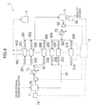
- Fig. 4 is a schematic diagram illustrating the entire dehydrator 1 according to the present exemplary embodiment. Note that the components similar to those of the above-described exemplary embodiments are provided with the same reference signs. Accordingly, the detailed description thereof will not be repeated here.
- the dehydrator 1 includes the first line 41 for allowing the treated fluid to flow from the first tank 2 to the second tank 3 and the second line 42 for allowing the treated fluid to flow from the second tank 3 to the first tank 2.
- the first line 41 includes the first pump 61 provided at a location close to the first tank 2 and the second line 42 includes the second pump 62 provided at a location close to the second tank 3.
- the first pump 61 and the second pump 62 are connected to the control unit 5.
- the first pump 61 is configured to pump the treated fluid from the first tank 2 to the second tank 3 under control of the control unit 5.
- the second pump 62 also is configured to pump the treated fluid contained in the second tank 3 into the first tank 2 under control of the control unit 5.
- the plurality of water separation membrane units 101 through 110 is divided into a first unit group including the units 101 through 105 and a second unit group including the units 106 through 110.
- the units 101 through 105 of the first unit group are provided on the first line 41 in parallel to one another and the units 106 through 110 of the second unit group are provided on the second line 42 in parallel to one another.
- the first heat exchanger 71 is provided between the first pump 61 and the first unit group including the units 101 through 105.
- the heat exchanger 72 is provided between the second pump 62 and the second unit group including the units 106 through 110.
- each of the water separation membrane units 101 through 110 includes a detector for detecting the malfunction occurring on the membrane container.
- the detector is connected to the control unit 5 and a detection signal is transmitted from the detector to the control unit 5.
- the control unit 5 executes control for closing both the first open-close valves 201 through 210 and the second open-close valves 301 through 310 corresponding to the water separation membrane unit to which the malfunction has occurred, among the water separation membrane units 101 through 110.
- the treated fluid (a crude ethanol aqueous solution) is supplied to the first tank 2.
- the treated fluid is intermittently supplied and the supply of the treated fluid is stopped when the first tank 2 is filled with the treated fluid.
- the first pump 61 pumps the treated fluid from the first tank 2 to the second tank 3.
- the treated fluid that flows through the first line 41 is heated by the first heat exchanger 71 and is allowed to flow into the first unit group including the units 101 through 105 arranged in parallel to one another.
- the steam drawn out by the first unit group including the units 101 through 105 during the operation described above flows into the third tank 4.
- the treated fluid flows into the second tank 3.
- the control unit 5 receives a concentration measured by the second ethanol concentration meter 3a of the second tank 3. If the concentration measured by the second ethanol concentration meter 3a has not reached a predetermined concentration yet, then the control unit 5 controls the second pump 62.
- the treated fluid flows from the second tank 3 to the first tank 2 via the second line 42.
- the treated fluid that flows through the second line 42 is heated by the second heat exchanger 72 and is then allowed to flow into the second unit group including the units 106 through 110 arranged in parallel to one another.
- the steam drawn out by the second unit group including the units 106 through 110 during the operation described above flows into the third tank 4.
- the treated fluid flows into the first tank 2.
- the above-described operation is repeated until the concentration of the treated fluid reaches the predetermined concentration.
- the treated fluid whose concentration has reached the predetermined concentration is finally recovered from the second tank 3 as product ethanol.
- the plurality of water separation membrane units 101 through 110 is divided into the first unit group including the units 101 through 105 and the second unit group including the units 106 through 110 and the units 101 through 105 of the first unit group are provided on the first line 41 in parallel to one another and the units 106 through 110 of the second unit group are provided on the second line 42 in parallel to one another. Accordingly, if any malfunction has occurred to any of the water separation membrane units 101 through 110, the maintenance and the replacement can be carried out only for the water separation membrane unit to which the malfunction has occurred, among the water separation membrane units 101 through 110, without stopping the entire dehydrator 1. Accordingly, it is enabled to stably operate the dehydrator 1.
- the dehydrator 1 of the present exemplary embodiment because the second line 42 for allowing the treated fluid to return from the second tank 3 to the first tank 2 is provided, the treated fluid can be securely dehydrated well enough to reach the predetermined concentration by allowing the treated fluid to repeatedly pass through the water separation membrane units 101 through 110.
- the plurality of water separation membrane units 101 through 110 is divided into two unit groups. Accordingly, the decrease of the velocity of flow of the treated fluid can be suppressed. As a result, the decrease of the performance of water separation by the membrane container can be suppressed.
- Fig. 5 is a schematic diagram illustrating the entire dehydrator 1 according to the present exemplary embodiment. Note that the components similar to those of the above-described exemplary embodiments are provided with the same reference signs. Accordingly, the detailed description thereof will not be repeated here.
- the dehydrator 1 includes an intermediate tank 9, which is provided between the first tank 2 and the second tank 3.
- the intermediate tank 9 is connected to both the first line 41 for allowing the treated fluid to flow from the first tank 2 to the second tank 3 and the second line 42 for allowing the treated fluid to flow from the second tank 3 to the first tank 2.
- the first line 41 includes an upstream side fluid line 41A for allowing the treated fluid to flow from the first tank 2 to the intermediate tank 9 and a downstream side fluid line 41B for allowing the treated fluid to flow from the intermediate tank 9 to the second tank 3.
- the second line 42 is constituted by an upstream side fluid line 42A for allowing the treated fluid to flow from the second tank 3 in the intermediate tank 9 and a downstream side fluid line 42B for allowing the treated fluid to flow from the intermediate tank 9 to the first tank 2.
- one intermediate tank 9 is provided in the example illustrated in Fig. 5 , two or more intermediate tanks 9 can be provided. If two or more intermediate tanks are provided, water separation membrane units can be provided in parallel to one another among the respective intermediate tanks.
- the upstream side fluid line 41A of the first line 41 includes the first pump 61, which is provided at a location close to the first tank 2, and the downstream side fluid line 41B of the first line 41 includes the second pump 62, which is provided at a location close to the intermediate tank 9. Furthermore, the upstream side fluid line 42A of the second line 42 includes a third pump 63, which is provided at a location close to the second tank 3, and the downstream side fluid line 42B of the second line 42 includes a fourth pump 64, which is provided at a location close to the intermediate tank 9.
- the dehydrator 1 includes twenty water separation membrane units 101 through 120.
- the plurality of water separation membrane units 101 through 120 is divided into the first unit group including the units 101 through 105, the second unit group including the units 106 through 110, a third unit group including the units 111 through 115, and a fourth unit group including the units 116 through 120.
- the units 101 through 105 of the first unit group are provided on the upstream side fluid line 41A of the first line 41 in parallel to one another and the units 106 through 110 of the second unit group are provided on the downstream side fluid line 41B of the first line 41 in parallel to one another.
- the units 111 through 115 of the third unit group are provided on the downstream side fluid line 42B of the second line 42 in parallel to one another and the units 116 through 120 of the fourth unit group are provided on the upstream side fluid line 42A of the second line 42 in parallel to one another.
- the first heat exchanger 71 is provided between the first pump 61 and the first unit group including the units 101 through 105.
- the second heat exchanger 72 is provided between the second pump 62 and the second unit group including the units 106 through 110.
- a third heat exchanger 73 is provided between the third pump 63 and the fourth unit group including the units 116 through 120.
- a fourth heat exchanger 74 is provided between the fourth pump 64 and the third unit group including the units 111 through 115.
- the dehydrator 1 includes a third tank 4A and the fourth tank 4B, into which the water separated from the treated fluid flows.
- the first unit group including the units 101 through 105 and the third unit group including the units 111 through 115 are connected to the third tank 4A via the steam valve. Accordingly, the steam drawn out by the first unit group including the units 101 through 105 and the third unit group including the units 111 through 115 flows into the third tank 4A.
- the second unit group including the units 106 through 110 and the fourth unit group including the units 116 through 120 are connected to the fourth tank 4B via the steam valve. Accordingly, the steam drawn out by the second unit group including the units 106 through 110 and the fourth unit group including the units 116 through 120 flows into the fourth tank 4B.
- the second line 42 includes a bypass line 10.
- the bypass line 10 is connected to the upstream side fluid line 42A of the second line 42 via the branch valve (not illustrated). As illustrated in Fig. 5 , the bypass line 10 connects between the upstream side fluid line 42A of the second line 42 and the first tank 2.
- the bypass line 10 bypasses two unit groups, i.e., the third unit group including the units 111 through 115 and the fourth unit group including the units 116 through 120, and is configured to allow the treated fluid from the second tank 3 to flow directly into the first tank 2.
- the bypass line 10 is provided so as to bypass two unit groups provided on the second line 42.
- the bypass line can be connected so as to bypass one or more unit group provided on the second line 42 to be connected to the intermediate tanks.
- the dehydrator 1 includes a control unit configured to control the operation of the entire dehydrator 1.
- the control unit is configured to control the first through the fourth pumps 61 through 64, first open-close valves 201 through 220, and second open-close valves 301 through 320.
- each of the water separation membrane units 101 through 120 includes a detector for detecting the malfunction occurring on the membrane container. The detector is connected to the control unit.
- control unit When the control unit receives the detection signal which indicates that malfunction has occurred to the membrane container, the control unit executes control for closing both the first open-close valves 201 through 220 and the second open-close valves 301 through 320 corresponding to the water separation membrane unit to which the malfunction has occurred, among the water separation membrane units 101 through 120.
- the maintenance and the replacement can be carried out only for the water separation membrane unit to which the malfunction has occurred, among the water separation membrane units 101 through 120.
- the treated fluid (a crude ethanol aqueous solution) is supplied to the first tank 2.
- the treated fluid is continuously supplied.
- the first pump 61 pumps the treated fluid from the first tank 2 into the intermediate tank 9.
- the treated fluid that flows through the upstream side fluid line 41A of the first line 41 is heated by the first heat exchanger 71 and flows into the units 101 through 105 of the first unit group provided in parallel to one another.
- the steam drawn out by the first unit group including the units 101 through 105 during the operation described above flows into the third tank 4A.
- the treated fluid that has passed through the first unit group including the units 101 through 105 flows into the intermediate tank 9.
- the second pump 62 pumps the treated fluid from the intermediate tank 9 into the second tank 3.
- the treated fluid that flows through the downstream side fluid line 41B of the first line 41 is heated by the second heat exchanger 72 and flows into the units 106 through 110 of the second unit group provided in parallel to one another.
- the steam drawn out by the second unit group including the units 106 through 110 during the operation described above flows into the fourth tank 4B.
- the treated fluid that has passed through the second unit group including the units 106 through 110 flows into the second tank 3.
- the control unit receives the concentration measured by a second ethanol concentration meter (not illustrated) of the second tank 3. Then, if the concentration measured by the second ethanol concentration meter has not reached a predetermined concentration, then the control unit controls the third pump 63. In this control, the control unit determines how many times the treated fluid is to pass through each unit group until the concentration of the treated fluid reaches the predetermined concentration according to the current concentration, for example. If it is determined that two unit groups (the third and the fourth unit groups including the units 111 through 120) can be bypassed according to the current concentration, then the control unit controls the branch valve provided between the bypass line 10 and the upstream side fluid line 42A of the second line 42 so that the treated fluid flows through the bypass line 10.
- the control unit controls the branch valve provided between the bypass line 10 and the upstream side fluid line 42A of the second line 42 so that the treated fluid flows through the bypass line 10.
- control unit executes control so that the treated fluid flows through the upstream side fluid line 42A of the second line 42.
- the following operation is executed when the treated fluid flows through the upstream side fluid line 42A of the second line 42.
- the treated fluid that flows through the upstream side fluid line 42A of the second line 42 is heated by the third heat exchanger 73 and flows into the units 116 through 120 of the fourth unit group provided in parallel to one another.
- the steam drawn out by the fourth unit group including the units 116 through 120 during the operation described above flows into the fourth tank 4B.
- the treated fluid that has passed through the fourth unit group including the units 116 through 120 flows into the intermediate tank 9.
- the fourth pump 64 pumps the treated fluid from the intermediate tank 9 to the first tank 2.
- the treated fluid that flows through the downstream side fluid line 42B of the second line 42 is heated by the fourth heat exchanger 74 and flows into the units 111 through 115 of the third unit group provided in parallel to one another.
- the steam drawn out by the third unit group including the units 111 through 115 during the operation described above flows into the third tank 4A.
- the treated fluid that has passed through the third unit group including the units 111 through 115 flows into the first tank 2.
- the above-described operation is repeated until the concentration of the treated fluid reaches the predetermined concentration.
- the treated fluid whose concentration has reached the predetermined concentration is finally recovered from the second tank 3 as product ethanol.
- the plurality of water separation membrane units 101 through 120 is divided into the first unit group including the units 101 through 105, the second unit group including the units 106 through 110, the third unit group including the units 111 through 115, and the fourth unit group including the units 116 through 120, and the units 101 through 105 of the first unit group are provided on the upstream side fluid line 41A of the first line 41 in parallel to one another, the units 106 through 110 of the second unit group are provided on the downstream side fluid line 41B of the first line 41 in parallel to one another, the units 111 through 115 of the third unit group are provided on the downstream side fluid line 42B of the second line 42 in parallel to one another, and the units 116 through 120 of the fourth unit group are provided on the upstream side fluid line 42A of the second line 42 in parallel to one another.
- the maintenance and the replacement can be carried out only for the water separation membrane unit to which the malfunction has occurred, among the water separation membrane units 101 through 120, without stopping the entire dehydrator 1. Accordingly, it is enabled to stably operate the dehydrator 1.
- the second line 42 includes the bypass line 10 and the bypass line 10 is configured to bypass two unit groups, i.e., the third unit group including the units 111 through 115 and the fourth unit group including the units 116 through 120, to allow the treated fluid to flow from the second tank 3 directly to the first tank 2. Accordingly, the number of times the treated fluid is to pass through the membrane container units can be appropriately changed. As a result, the concentration of the treated fluid can be finely adjusted.
- the dehydrator 1 of the present exemplary embodiment the plurality of water separation membrane units 101 through 120 is divided into four unit groups. Accordingly, the decrease of the velocity of flow of the treated fluid can be suppressed. As a result, the decrease of the performance of water separation by the membrane container can be suppressed. Furthermore, according to the dehydrator 1 of the present exemplary embodiment, the dehydrator 1 includes the intermediate tank 9, which is provided between the first tank 2 and the second tank 3. With the above-described configuration, because the treated fluid can be stored also in the intermediate tank 9, the entire dehydrator 1 can be operated while continuously supplying the treated fluid to the first tank 2. According to the dehydrator 1 of the present exemplary embodiment, the product ethanol can be continuously recovered by continuously supplying the ethanol aqueous solution, which is the material of the product ethanol, to the dehydrator 1.
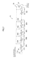
- Fig. 6 is a schematic diagram illustrating the entire dehydrator 1 according to the fifth exemplary embodiment of the present invention. Note that the components similar to those of the above-described exemplary embodiments are provided with the same reference signs. Accordingly, the detailed description thereof will not be repeated here.
- the dehydrator 1 includes a first intermediate tank 9A and a second intermediate tank 9B, which are provided between the first tank 2 and the second tank 3.
- the first intermediate tank 9A and the second intermediate tank 9B are connected to both the first line 41 for allowing the treated fluid to flow from the first tank 2 to the second tank 3 and the second line 42 for allowing the treated fluid to flow from the second tank 3 to the first tank 2.
- the first intermediate tank 9A and the second intermediate tank 9B is provided with an ethanol concentration meter (not illustrated) for measuring the concentration of ethanol contained in the treated fluid.
- the first line 41 is constituted by the upstream side fluid line 41A for allowing the treated fluid to flow from the first tank 2 to the first intermediate tank 9A, an intermediate fluid line 41B for allowing the treated fluid to flow from the first intermediate tank 9A to the second intermediate tank 9B, and a downstream side fluid line 41C for allowing the treated fluid to flow from the second intermediate tank 9B to the second tank 3.
- the second line 42 is constituted by the upstream side fluid line 42A for allowing the treated fluid to flow from the second tank 3 to the second intermediate tank 9B, an intermediate fluid line 42B for allowing the treated fluid to flow from the second intermediate tank 9B to the first intermediate tank 9A, and a downstream side fluid line 42C for allowing the treated fluid to flow from the first intermediate tank 9A to the first tank 2.
- Fig. 6 illustrates the embodiment in which two intermediate tanks (the first intermediate tank 9A and the second intermediate tank 9B) are provided, three or more intermediate tanks can be provided. If three or more intermediate tanks are provided, water separation membrane units can be provided among the intermediate tanks in parallel to one another.
- the upstream side fluid line 41A of the first line 41 is provided with the first pump 61 provided at a location close to the first tank 2.
- the intermediate fluid line 41B of the first line 41 is provided with the second pump 62, which is provided at a location close to the first intermediate tank 9A.
- the downstream side fluid line 41C of the first line 41 is provided with the second pump 63, which is provided at a location close to the second intermediate tank 9B.
- the upstream side fluid line 42A of the second line 42 is provided with the fourth pump 64, which is provided at a location close to the second tank 3.
- the intermediate fluid line 42B of the second line 42 is provided with a fifth pump 65, which is provided at a location close to the second intermediate tank 9B.
- the downstream side fluid line 42C of the second line 42 is provided with a sixth pump 66, which is provided at a location close to the first intermediate tank 9A.
- the dehydrator 1 includes thirty water separation membrane units through 101 through 130.
- the plurality of water separation membrane units 101 through 130 is divided into the first unit group including the units 101 through 105, the second unit group including the units 106 through 110, the third unit group including the units 111 through 115, the fourth unit group including the units 116 through 120, a fifth unit group including the units 121 through 125, and a sixth unit group including the units 126 through 130.
- the units 101 through 105 of the first unit group are provided on the upstream side fluid line 41A of the first line 41 in parallel to one another
- the units 106 through 110 of the second unit group are provided on the intermediate fluid line 41B of the first line 41 in parallel to one another
- the units 111 through 115 of the third unit group are provided on the downstream side fluid line 41C of the first line 41 in parallel to one another.
- the units 116 through 120 of the fourth unit group are provided on the downstream side fluid line 42C of the second line 42 in parallel to one another
- the units 121 through 125 of the fifth unit group are provided on the intermediate fluid line 42B of the second line 42 in parallel to one another
- the units 126 through 130 of the sixth unit group are provided on the upstream side fluid line 42A of the second line 42 in parallel to one another.
- the first heat exchanger 71 is provided between the first pump 61 and the first unit group including the units 101 through 105.
- the second heat exchanger 72 is provided between the second pump 62 and the second unit group including the units 106 through 110.
- the third heat exchanger 73 is provided between the third pump 63 and the third unit group including the units 111 through 115.
- the fourth heat exchanger 74 is provided between the third pump 63 and the sixth unit group including the units 126 through 130.
- a fifth heat exchanger 75 is provided between the fifth pump 65 and the fifth unit group including the units 121 through 125.
- a sixth heat exchanger 76 is provided between the sixth pump 66 and the fourth unit group including the units 116 through 120.
- the second line 42 includes a first bypass line 11 and a second bypass line 12.
- the first bypass line 11 is connected to the intermediate fluid line 42B of the second line 42 via a branch valve (not illustrated).
- the first bypass line 11 connects between the intermediate fluid line 42B of the second line 42 and the first tank 2.
- the first bypass line 11 is configured to bypass two unit groups, i.e., the fourth unit group including the units 116 through 120 and the fifth unit group including the units 121 through 125, to allow the treated fluid to flow directly from the second intermediate tank 9B into the first tank 2.
- the second bypass line 12 is connected to the upstream side fluid line 42A of the second line 42 via a branch valve (not illustrated).
- the second bypass line 12 connects between the upstream side fluid line 42A of the second line 42 and the first intermediate tank 9A.
- the second bypass line 12 is configured to bypass two unit groups, i.e., the fifth unit group including the units 121 through 125 and the sixth unit group including the units 126 through 130, to allow the treated fluid to flow directly from the second tank 3 into the first intermediate tank 9A.
- the first and the second bypass lines 11 and 12 bypass two unit groups provided on the second line 42.
- the bypass lines can be provided so as to bypass one or more unit groups provided on the second line 42 to be connected to the intermediate tanks.
- the dehydrator 1 includes a plurality of tanks into which the water separated from the treated fluid flows, similarly to the above-described fourth exemplary embodiment.
- the respective water separation membrane units 101 through 130 are connected to the plurality of tanks. Accordingly, the steam drawn out by each of the water separation membrane units 101 through 130 flows into the tanks.
- the dehydrator 1 includes a control unit configured to control the operation of the entire dehydrator 1.
- the control unit is configured to control the first through the sixth pumps 61 through 66, first open-close valves 201 through 230, and second open-close valves 301 through 330.
- each of the water separation membrane units 101 through 130 includes a detector for detecting the malfunction occurring on the membrane container. The detector is connected to the control unit.
- control unit When the control unit receives the detection signal which indicates that malfunction has occurred to the membrane container, the control unit executes control for closing both the first open-close valves 201 through 230 and the second open-close valves 301 through 330 corresponding to the water separation membrane unit to which the malfunction has occurred, among the water separation membrane units 101 through 130.
- the maintenance and the replacement can be carried out only for the water separation membrane unit to which the malfunction has occurred, among the water separation membrane units 101 through 130.
- the treated fluid (a crude ethanol aqueous solution) is supplied to the first tank 2.
- the treated fluid is continuously supplied.
- the first pump 61 pumps the treated fluid from the first tank 2 into the first intermediate tank 9A.
- the treated fluid that flows through the upstream side fluid line 41A of the first line 41 is heated by the first heat exchanger 71 and flows into the units 101 through 105 of the first unit group, which are provided in parallel to one another. Then, the treated fluid that has passed through the first unit group including the units 101 through 105 flows into the first intermediate tank 9A.
- the second pump 62 pumps the treated fluid from the first intermediate tank 9A into the second intermediate tank 9B.
- the treated fluid that flows through the downstream side fluid line 41B of the first line 41 is heated by the second heat exchanger 72 and flows into the units 106 through 110 of the second unit group provided in parallel to one another. Then, the treated fluid that has passed through the second unit group including the units 106 through 110 flows into the second intermediate tank 9B.
- the third pump 63 pumps the treated fluid from the second intermediate tank 9B to the second tank 3.
- the treated fluid that flows through the downstream side fluid line 41C of the first line 41 is heated by the third heat exchanger 73 and flows into the units 111 through 115 of the third unit group provided in parallel to one another.
- the treated fluid that has passed through the third unit group including the units 111 through 115 flows into the second tank 3.
- the control unit receives the concentration measured by a second ethanol concentration meter (not illustrated) of the second tank 3. Then, if the concentration measured by the second ethanol concentration meter has not reached a predetermined concentration, then the control unit controls the fourth pump 64. In this control, the control unit determines how many times the treated fluid is to pass through each unit group until the concentration of the treated fluid reaches the predetermined concentration according to the current concentration, for example. If it is determined that two unit groups (the fifth and the sixth unit groups including the units 121 through 130) can be bypassed according to the current concentration, then the control unit controls the branch valve provided between the second bypass line 12 and the upstream side fluid line 42A of the second line 42 so that the treated fluid flows through the second bypass line 12.
- control unit executes control so that the treated fluid flows through the upstream side fluid line 42A of the second line 42.
- the following operation is executed when the treated fluid flows through the upstream side fluid line 42A of the second line 42.
- the treated fluid that flows through the upstream side fluid line 42A of the second line 42 is heated by the fourth heat exchanger 74.
- the treated fluid then flows into the units of the sixth unit group including the units 126 through 130 provided in parallel to one another. Then, the treated fluid that has passed through the sixth unit group including the units 126 through 130 flows into the second intermediate tank 9B.
- the control unit receives the concentration measured by the second ethanol concentration meter of the second intermediate tank 9B. Consequently, the control unit controls the fifth pump 65. In this control, the control unit determines how many times the treated fluid is to pass through each unit group until the concentration of the treated fluid reaches the predetermined concentration according to the current concentration. If it is determined that two unit groups (the fourth and the fifth unit group including the units 116 through 125) can be bypassed according to the current concentration, then the control unit controls the branch valve provided between the first bypass line 11 and the intermediate fluid line 42B of the second line 42 so that the treated fluid flows through the first bypass line 11. Otherwise, the control unit executes control so that the treated fluid flows through the intermediate fluid line 42B of the second line 42.
- the following operation is executed when the treated fluid flows through the intermediate fluid line 42B of the second line 42.
- the treated fluid that flows through the intermediate fluid line 42B of the second line 42 is heated by the fifth heat exchanger 75.
- the treated fluid then flows into the units of the fifth unit group including the units 121 through 125 provided in parallel to one another. Then, the treated fluid that has passed through the fifth unit group including the units 121 through 125 flows into the first intermediate tank 9A.
- the sixth pump 66 pumps the treated fluid from the first intermediate tank 9A into the first tank 2.
- the treated fluid that flows through the downstream side fluid line 42C of the second line 42 is heated by the sixth heat exchanger 76.
- the treated fluid then flows into the units of the fourth unit group including the units 116 through 120 provided in parallel to one another.
- the treated fluid that has passed through the fourth unit group including the units 116 through 120 flows into the first tank 2.
- the above-described operation is repeated until the concentration of the treated fluid reaches the predetermined concentration.
- the treated fluid whose concentration has reached the predetermined concentration is finally recovered from the second tank 3 as product ethanol.
- the plurality of water separation membrane units 101 through 130 is divided into the first unit group including the units 101 through 105, the second unit group including the units 106 through 110, the third unit group including the units 111 through 115, the fourth unit group including the units 116 through 120, the fifth unit group 121 through 125, and the sixth unit group including the units 126 through 130.
- the units 101 through 105 of the first unit group are provided on the upstream side fluid line 41A of the first line 41 in parallel to one another
- the units 106 through 110 of the second unit group are provided on the intermediate fluid line 41B of the first line 41 in parallel to one another
- the units 111 through 115 of the third unit group are provided on the downstream side fluid line 41C of the first line 41 in parallel to one another
- the units 116 through 120 of the fourth unit group are provided on the downstream side fluid line 42C of the second line 42 in parallel to one another
- the units 121 through 125 of the fifth unit group are provided on the intermediate fluid line 42B of the second line 42 in parallel to one another
- the units 126 through 130 of the sixth unit group are provided on the upstream side fluid line 42A of the second line 42 in parallel to one another.
- the maintenance and the replacement can be carried out only for the water separation membrane unit to which the malfunction has occurred, among the water separation membrane units 101 through 130, without stopping the entire dehydrator 1. Accordingly, it is enabled to stably operate the dehydrator 1.
- the second line 42 includes the first bypass line 11 and the second bypass line 12.
- the first bypass line 11 is configured to bypass two units, i.e., the fourth unit group including the units 116 through 120 and the fifth unit group including the units 121 through 125, to allow the treated fluid to flow directly from the second intermediate tank 9B into the first tank 2
- the second bypass line 12 is configured to bypass the fifth unit group including the units 121 through 125 and the sixth unit group including the units 126 through 130 to allow the treated fluid to flow directly from the second tank 3 into the first intermediate tank 9A. Accordingly, the number of times the treated fluid is to pass through the membrane container units can be appropriately changed. As a result, the concentration of the treated fluid can be finely adjusted.
- the dehydrator 1 of the present exemplary embodiment the plurality of water separation membrane units 101 through 130 is divided into six unit groups. Accordingly, the decrease of the velocity of flow of the treated fluid can be suppressed. As a result, the decrease of the performance of water separation by the membrane container can be suppressed.
- the dehydrator 1 is provided with the first intermediate tank 9A and the second intermediate tank 9B, which are provided between the first tank 2 and the second tank 3. With the above-described configuration, because the treated fluid can be stored also in the first intermediate tank 9A and the second intermediate tank 9B, the entire dehydrator 1 can be operated while continuously supplying the treated fluid to the first tank 2.
- the product ethanol can be continuously recovered by continuously supplying the ethanol aqueous solution, which is the material of the product ethanol, to the dehydrator 1.
- the number of the water separation membrane units of the present invention is not limited to these numbers. To paraphrase this, the number of the water separation membrane units can be appropriately changed according to the flow rate of the treated fluid.
- the heat exchanger is provided for each fluid line. However, if the change in the temperature of the treated fluid is small, it is not necessary to provide the heat exchanger for all the fluid lines.
- the first bypass line 11 and the second bypass line 12 are configured to bypass two unit groups including the water separation membrane units.
- the bypass lines of the present invention are not limited to those described above. To paraphrase this, it is useful if bypass lines configured to bypass three unit groups to allow the treated fluid to flow directly from the second tank 3 into the first tank 2 is provided.
- Reference Signs List 1 Dehydrator 2: First tank 3: Second tank 2a, 3a: Ethanol concentration meter 4: Third tank 5: Control unit 9, 9A, 9B: Intermediate tank 10, 11, 12: Bypass line 41: First line 42: Second line 41A, 41B, 41C: Fluid line for the first line (first fluid line) 42A, 42B, 42C: Fluid line for the second line (second fluid line) 61, 62, 63, 64, 65, 66: Pump 71, 72, 73, 74, 75, 76: Heat exchanger 81, 82: Bypass tube 101 through 130: Water separation membrane unit (membrane container unit) 101a through 110a Detector 201 through 230: First open-close valve 301 through 330: Second open-close valve
Landscapes
- Chemical & Material Sciences (AREA)
- Organic Chemistry (AREA)
- Engineering & Computer Science (AREA)
- Water Supply & Treatment (AREA)
- Chemical Kinetics & Catalysis (AREA)
- Separation Using Semi-Permeable Membranes (AREA)
Abstract
Description
- The present invention relates to a dehydrator for dehydrating a mixture (treated fluid) of water with ethanol which forms an azeotropic composition with water.
- In recent years, ethanol has attracted attention as a fuel source alternative to petroleum fuels. However, for adopting ethanol as a fuel, it is necessary to purify, by distillation, a crude product obtained from a biomass such as corn, and then to perform dehydration until at least 99.5 wt% is reached.
- Known conventional dehydration methods include a method for separating water from the treated fluid by the pervaporation method (penetrative vaporization (PV) method) using a water separation membrane (see, for example, Patent Literature 1). In the dehydrator discussed by
Patent Literature 1, a plurality of water separation membranes is arranged so that the water separation membranes are arranged in series in the inside of a shell part. In this dehydrator, the treated fluid containing water passes through the serially arranged water separation membranes one after another. In this manner, water is separated from the treated fluid. -
Fig. 7 is a schematic diagram which illustrates the entire conventional dehydrator. Referring toFig. 7 , adehydrator 31 includes afirst tank 32, to which the treated fluid (a crude ethanol aqueous solution) is supplied, asecond tank 33, into which dehydrated product ethanol flows, aline 34 for allowing the treated fluid to flow from thefirst tank 2 to thesecond tank 3, a plurality of waterseparation membrane units 35A through 35J provided between thefirst tank 2 and thesecond tank 3, and athird tank 36, into which the water separated from the treated fluid flows. - As illustrated in
Fig. 7 , the plurality of waterseparation membrane units 35A through 35J is connected in series. Each ofheat exchangers 37A through 37J is provided among the waterseparation membrane units 35A through 35J. In addition, for each of the plurality of waterseparation membrane units 35A through 35J, each ofbypass lines 38A through 38J for bypassing the waterseparation membrane units 35A through 35J is provided. -
- PTL 1: Japanese Patent Application Laid-Open No.
2010-115596 - PTL 2:
US 2008/0,164,207 A1 - PTL 3:
WO 2008/111671 A1 - A first problem, which arises in the configuration illustrated in
Fig. 7 and the conventional configuration discussed byPatent Literature 1, may arise because the water separation membrane units are arranged in series in this configuration. For example, if water separation membrane units are arranged in series and if any malfunction has occurred in a water separation membrane unit on an upstream side out of the water separation membrane units, the malfunction may affect the water separation membrane units on a downstream side. More specifically, if any malfunction has occurred in a water separation membrane unit on the upstream side, it becomes necessary to stop the entire dehydrator and to execute a maintenance operation. Accordingly, a problem may arise such that the dehydrator cannot be stably operated. In addition, in this case, although the operation of the dehydrator can be continued by using the bypass lines, the treated fluid may not be dehydrated until a predetermined concentration is achieved because the number of times the treated fluid passes through the water separation membrane units is reduced. - Furthermore, a second problem may arise such that in the configuration that uses water separation membranes as illustrated in
Fig. 7 and as discussed byPatent Literature 1, the water separation performance may greatly vary according to the velocity of flow of the treated fluid. -
Fig. 8 illustrates a ratio of quantity of permeated water to the quantity of permeation of a matter (containing water and ethanol) that has permeated through water separation membranes. Referring toFig. 8 , the ratio of quantity of permeated water is about 1 at the velocity of flow of approximately 0.6 m/s. The ratio of quantity of permeated water to the quantity of matter permeated through the water separation membranes becomes lower as the velocity of flow of the treated fluid becomes lower. As described above, if water separation membranes are used and if the velocity of flow of the treated fluid is low, the ratio of permeated water to the matter permeated through the water separation membranes becomes low. As a result, the water separation performance may degrade. - In addition, if the velocity of flow of the treated fluid is low, the problem may arise such that concentration polarization may occur in the vicinity of the water separation membranes. The concentration polarization is a phenomenon that may occur in the vicinity of water separation membranes, in which a dissolved matter (water in the example illustrated in
Fig. 8 ) that does not permeate through water separation membranes produce a gradient of concentration in the direction perpendicular to the water separation membrane. -
Figs. 9A and 9B illustrate a case where the concentration gradient is produced and another case where the concentration gradient is not produced. More specifically,Fig. 9A illustrates a case where the velocity of flow of the treated fluid is low.Fig. 9B illustrates a case where the velocity of flow of the treated fluid is high. As illustrated in a chart (1) ofFig. 9A , if the velocity of flow of the treated fluid is low, the concentration of water becomes lower as the distance to the water separation membrane becomes smaller while the concentration of water becomes higher as the distance to the water separation membrane in the direction perpendicular to the water separation membrane (in the direction of the cross section) becomes greater. As a result of such concentration polarization, referring to the change of the concentration of water in the direction of flow of the treated fluid illustrated in the chart (2) ofFig. 9A , the concentration of water hardly becomes low. Accordingly, it is known that the water separation performance is problematically low. On the other hand, as illustrated in the chart (1) ofFig. 9B , if the velocity of flow of the treated fluid is sufficiently high, water permeates through the water separation membranes. Accordingly, no concentration polarization occurs. As a result, referring to the change of the concentration of water in the direction of flow of the treated fluid illustrated in the chart (2) ofFig. 9B , the concentration of water gradually becomes lower. Accordingly, it is known that a sufficiently high water separation performance is achieved. - As described above, in the configuration that uses water separation membranes, a sufficiently high water separation performance cannot be achieved if the velocity of flow of the treated fluid becomes low. Accordingly, in this case, the treated fluid may not be dehydrated well enough to reach a predetermined concentration. Therefore, the configuration that uses water separation membranes requires certain measures for securely dehydrating the treated fluid well enough to reach a predetermined concentration.
- The present invention is devised to solve the above-described problems. The object of the present invention is to provide a dehydrator which can be safely operated if any malfunction has occurred to a water separation membrane unit and which is capable of securely dehydrating the treated fluid well enough to reach the predetermined concentration.
- In order to solve the above-described problems arising in the conventional techniques, according to an aspect of the present invention, a dehydrator configured to separate water from treated fluid includes: a first tank configured to store the treated fluid before water is separated therefrom; a second tank into which the treated fluid whose water has been separated therefrom flows; and a plurality of membrane container units having a separation membrane configured to separate water from the treated fluid, and provided between the first tank and the second tank and in parallel to one another along a direction of flow of the treated fluid. The treated fluid is configured to reciprocate between the first tank and the second tank and is configured to pass through the plurality of membrane container units for a plurality of times.
- According to another aspect of the present invention, the dehydrator further includes a first line configured to allow the treated fluid to reciprocate between the first tank and the second tank. In the dehydrator, the plurality of membrane container units is arranged on the first line in parallel to one another and the treated fluid is configured, after all the treated fluid has flowed from the first tank to the second tank via the plurality of membrane container units provided on the first line and no treated fluid remains in the first tank, to flow from the second tank to the first tank via the plurality of membrane container units provided on the first line.
- According to yet another aspect of the present invention, the dehydrator further includes the first line configured to allow the treated fluid to flow from the first tank to the second tank, and a second line configured to allow the treated fluid to flow from the second tank to the first tank. In the dehydrator, the plurality of membrane container units is arranged in parallel to one another and the treated fluid is configured, after all the treated fluid has flowed from the first tank to the second tank via the plurality of membrane container units provided on the first line and no treated fluid remains in the first tank, to flow from the second tank to the first tank via the second line.
- According to still yet another aspect of the present invention, the dehydrator further includes the first line configured to allow the treated fluid to flow from the first tank to the second tank, and the second line configured to allow the treated fluid to flow from the second tank to the first tank. In the dehydrator, the plurality of membrane container units is divided into a first unit group including units provided on the first line and in parallel to one another and a second unit group including units provided on the second line and in parallel to one another, and the treated fluid is configured, after all the treated fluid has flowed from the first tank to the second tank via the first unit group provided on the first line and no treated fluid remains in the first tank, to flow from the second tank to the first tank via the second unit group provided on the second line.
- According to still yet another aspect of the present invention, the dehydrator further includes the first line configured to allow the treated fluid to flow from the first tank to the second tank, the second line configured to allow the treated fluid to flow from the second tank to the first tank, and at least one intermediate tank provided between the first tank and the second tank and connected to both the first line and the second line. In the dehydrator, the first line is divided into a plurality of first fluid lines provided across the intermediate tank and the second line is divided into a plurality of second fluid lines provided across the intermediate tank, the plurality of membrane container units is divided into unit groups including as many units as a total number of the first fluid line and the second fluid line and units included in the unit group of the plurality of membrane container units are provided in parallel to one another on each of the first fluid line and the second fluid line, the treated fluid is configured to flow from the first tank to the second tank successively via the units included in the unit group provided on the first line and the intermediate tank and is configured to flow from the second tank to the first tank successively via the units included in the unit group provided on the second line and the intermediate tank, the second line includes at least one bypass line, and the bypass line is configured to bypass one or more units of the unit group provided on the second line, to allow the treated fluid to return to the intermediate tank or the first tank.
- According to the dehydrator of an aspect of the present invention, because a plurality of membrane container units is provided in parallel to one another, if any malfunction has occurred to any water separation membrane unit, the maintenance and the replacement can be carried out only for the water separation membrane unit to which the malfunction has occurred without stopping the entire dehydrator. Accordingly, it is enabled to stably operate the dehydrator.
- In addition, although the velocity of flow of the treated fluid may become low and the performance of water separation by the membrane container units may become low if a plurality of membrane container units is provided in parallel to one another, the treated fluid can be securely dehydrated well enough to reach a predetermined concentration by allowing the treated fluid to reciprocate between the first tank and the second tank and by allowing the treated fluid to repeatedly pass through the membrane container units.
- Furthermore, according to the dehydrator of the present invention, the second line includes at least one bypass line and the bypass line is configured to bypass one or more units included in the unit group provided on the second line to allow the treated fluid to return to the intermediate tank or the first tank. Accordingly, the number of times the treated fluid is to pass through the membrane container units can be appropriately changed. As a result, the concentration of the treated fluid can be finely adjusted.
-
-
Fig. 1 is a schematic diagram illustrating the entire dehydrator according to a first exemplary embodiment of the present invention. -
Fig. 2 is a diagram illustrating a trial calculation of the transition of a concentration of ethanol obtained by dehydrating a crude ethanol aqueous solution by using the dehydrator according to the first exemplary embodiment of the present invention. -
Fig. 3 is a schematic diagram illustrating the entire dehydrator according to a second exemplary embodiment of the present invention. -
Fig. 4 is a schematic diagram illustrating the entire dehydrator according to a third exemplary embodiment of the present invention. -
Fig. 5 is a schematic diagram illustrating the entire dehydrator according to a fourth exemplary embodiment of the present invention. -
Fig. 6 is a schematic diagram illustrating the entire dehydrator according to a fifth exemplary embodiment of the present invention. -
Fig. 7 is a schematic diagram illustrating the entire conventional dehydrator. -
Fig. 8 is a diagram illustrating a ratio of the quantity of permeation of water to the quantity of permeation of a matter (containing water and ethanol) that has permeated through water separation membranes. -
Fig. 9A is a diagram illustrating a case in which concentration polarization has occurred because the velocity of flow of treated fluid is low. -
Fig. 9B is a diagram illustrating a case in which the concentration polarization has not occurred because the velocity of flow of the treated fluid is high. - Hereinbelow, a dehydrator according to the first exemplary embodiment of the present invention will be described below with reference to the attached drawings.
Fig. 1 is a schematic diagram illustrating the entire dehydrator according to the present exemplary embodiment. - The
dehydrator 1 according to the present exemplary embodiment is configured to dehydrate a crude ethanol aqueous solution used as treated fluid. The inventors assume approximately 91 wt % of the concentration of ethanol for the concentration of the crude ethanol aqueous solution. Thedehydrator 1 is configured to treat and purify crude ethanol containing ethanol as an organic component to finally produce product ethanol (absolute ethanol) whose ethanol concentration is in the range of 99.5 to 99.8 wt %. - Referring to
Fig. 1 , thedehydrator 1 includes afirst tank 2, to which treated fluid (a crude ethanol aqueous solution) is supplied, asecond tank 3, into which the dehydrated product ethanol flows, afirst line 41 for allowing the treated fluid to reciprocate between thefirst tank 2 and thesecond tank 3, a plurality of (ten in the present exemplary embodiment) waterseparation membrane units 101 through 110 provided to thefirst line 41, athird tank 4, into which water separated from the treated fluid flows, and acontrol unit 5 configured to control the operation of theentire dehydrator 1. - As illustrated in
Fig. 1 , thefirst tank 2 is provided with a firstethanol concentration meter 2a. In addition, thesecond tank 3 is provided with a secondethanol concentration meter 3a. The firstethanol concentration meter 2a and the secondethanol concentration meter 3a are connected to thecontrol unit 5. Detection signals are transmitted from the firstethanol concentration meter 2a and the secondethanol concentration meter 3a to thecontrol unit 5. - As illustrated in
Fig. 1 , thefirst line 41 is provided with afirst pump 61, which is provided at a location close to thefirst tank 2, and asecond pump 62, which is provided at a location close to thesecond tank 3. Thefirst pump 61 and thesecond pump 62 are connected to thecontrol unit 5. Thefirst pump 61 is configured to pump the treated fluid stored in thefirst tank 2 into thesecond tank 3 under control of thecontrol unit 5. Thesecond pump 62 also is configured to pump the treated fluid stored in thesecond tank 3 into thefirst tank 2 under control of thecontrol unit 5. With the above-described configuration, the treated fluid is allowed to reciprocate through thefirst line 41 between thefirst tank 2 and thesecond tank 3. - As illustrated in
Fig. 1 , a plurality of waterseparation membrane units 101 through 110 is provided on thefirst line 41 in parallel to one another. First open-close valves 201 through 210 are provided on the side of thefirst tank 2 of the waterseparation membrane units 101 through 110. In addition, second open-close valves 301 through 310 are provided on the side of thesecond tank 3 of the waterseparation membrane units 101 through 110. As illustrated inFig. 1 , the first open-close valves 201 through 210 and the second open-close valves 301 through 310 are connected to thecontrol unit 5 and are configured to open and close under control of thecontrol unit 5. - Each of the water
separation membrane units 101 through 110 is provided with a membrane container (not illustrated), which will be described below, and is configured to separate water by the pervaporation method in which the supply side is a liquid phase and the permeation side is a gas phase. In the present exemplary embodiment, for the membrane container of the waterseparation membrane units 101 through 110, a flow path for the treated fluid is referred to as the "supply side" and the outside of the membrane container is referred to as the "permeation side". - In the present exemplary embodiment, the membrane container is constituted by a combination of a plurality of tubular-type water separation membranes or a monolith-type water separation membrane and has a columnar shape. As the membrane container, an inorganic porous membrane in which holes on the order of nanometers or smaller are controlled precisely can be used. The porous membrane having fine holes achieves a molecule sieving effect of allowing small-molecule gases to pass through and exclude large-molecule gases, and exhibits a behavior of activation diffusion in which the permeation factor thereof increases with the increase in temperature. As an example of a porous membrane having fine holes, a carbon membrane, a silica membrane, and a zeolite membrane can be mentioned.
- Also, the inorganic water separating membrane described in Japanese Patent No.
2808479 2808479 - Note that, besides the inorganic water separation membrane, an organic membrane such as a polyvinyl alcohol membrane, a polyimide membrane or a polyamide membrane can be used as the water separation membrane. Note that the material and the size of the membrane container and the diameter, the quantity, and the like of the flow paths can be selected by a person having ordinary skill in the art according to their purpose of use.
- The dehydration treatment by the membrane container is carried out by using a decompression device (not illustrated). By decompressing the permeation side of the membrane container by using the decompression device, the water contained in the treated fluid that passes through vacuum device the flow path of the membrane container becomes steam. The steam is drawn out to the permeation side. As illustrated in
Fig. 1 , the waterseparation membrane units 101 through 110 are respectively connected to thethird tank 4 via thesteam valves 401 through 410. The steam drawn out by each of the waterseparation membrane units 101 through 110 flows into thethird tank 4. - As illustrated in
Fig. 1 , on thefirst line 41, afirst heat exchanger 71 is provided between thefirst pump 61 and the plurality of waterseparation membrane units 101 through 110. In addition, on thefirst line 41, asecond heat exchanger 72 is provided between thesecond pump 62 and the plurality of waterseparation membrane units 101 through 110. Thefirst heat exchanger 71 and thesecond heat exchanger 72 apply heat to raise the temperature of the treated fluid that flows into the waterseparation membrane units 101 through 110 to prevent the temperature of the treated fluid from dropping. - As illustrated in
Fig. 1 , on thefirst line 41, afirst bypass tube 81 for bypassing thefirst pump 61 and thefirst heat exchanger 71 is provided. Both ends of thefirst bypass tube 81 are connected to thefirst line 41 via a branch valve (not illustrated). In addition, on thefirst line 41, asecond bypass tube 82 for bypassing thesecond pump 62 and thesecond heat exchanger 72 is provided. Both ends of thesecond bypass tube 82 are connected to thefirst line 41 via a branch valve (not illustrated). Note that the branch valve is connected to thecontrol unit 5 and is configured to open and close under control of thecontrol unit 5. - As illustrated in
Fig. 1 , the waterseparation membrane units 101 through 110 are provided withdetectors 101a through 110a configured to detect malfunction occurring on the membrane container, respectively. Thedetectors 101a through 110a are configured to continuously monitor the state of the membrane containers and can carry out on-line detection of malfunction. For example, if the quantity of permeation is decreased by clogging, thedetectors 101a through 110a detect that the decrease in outlet temperature on the supply side is small. Also, if the quantity of permeation is increased by a malfunction occurring in the membrane container, thedetectors 101a through 110a can detect that the decrease in temperature on the permeation side is large. Furthermore, thedetectors 101a through 110a can detect that the outlet concentration on the supply side has been changed due to the change in the quantity of permeation. - As illustrated in
Fig. 1 , thedetectors 101a through 110a are connected to thecontrol unit 5 and are configured to transmit detection signals to thecontrol unit 5. When thecontrol unit 5 receives the detection signal which indicates that malfunction has occurred to the membrane container, thecontrol unit 5 executes control for closing both the first open-close valves 201 through 210 and the second open-close valves 301 through 310 corresponding to the water separation membrane unit to which the malfunction has occurred, among the waterseparation membrane units 101 through 110. With the above-described configuration, the maintenance and the replacement can be carried out only for the water separation membrane unit to which the malfunction has occurred, among the waterseparation membrane units 101 through 110. - Now, an operation of the
dehydrator 1 according to the present exemplary embodiment will be described below with reference to the attached drawings. - As illustrated in
Fig. 1 , at the start of the operation, the treated fluid (a crude ethanol aqueous solution) is supplied to thefirst tank 2. The treated fluid is intermittently supplied and the supply of the treated fluid is stopped when thefirst tank 2 is filled with the treated fluid. Then, thecontrol unit 5 controls the branch valve provided between thefirst line 41 and thefirst bypass tube 81 to allow the treated fluid to flow into thefirst line 41. After that, thefirst pump 61 pumps the treated fluid from thefirst tank 2 to thesecond tank 3. The treated fluid that flows through thefirst line 41 is heated by thefirst heat exchanger 71 and is allowed to flow into the plurality of waterseparation membrane units 101 through 110 provided in parallel to one another. The steam drawn out by each of the waterseparation membrane units 101 through 110 during the operation described above flows into thethird tank 4. Then, thecontrol unit 5 controls the branch valve provided between thefirst line 41 and thesecond bypass tube 82 to allow the treated fluid to flow into thesecond bypass tube 82. Then, the treated fluid that has passed through thesecond bypass tube 82 flows into thesecond tank 3. - After all the treated fluid has flowed from the
first tank 2 to thesecond tank 3, thecontrol unit 5 receives a concentration measured by the secondethanol concentration meter 3a of thesecond tank 3. If the concentration measured by the secondethanol concentration meter 3a has not reached a predetermined concentration yet, then thecontrol unit 5 executes control for allowing the treated fluid to flow from thesecond tank 3 to thefirst tank 2 in the following manner. At the start of the control, thecontrol unit 5 controls the branch valve provided between thefirst line 41 and thesecond bypass line 82 to allow the treated fluid to flow into thefirst line 41. Consequently, thesecond pump 62 pumps the treated fluid from thesecond tank 3 to thefirst tank 2. The treated fluid that flows through thefirst line 41 is heated by thesecond heat exchanger 72 and is allowed to flow into the plurality of waterseparation membrane units 101 through 110 provided in parallel to one another. The steam drawn out by each of the waterseparation membrane units 101 through 110 during the above-described operation flows into thethird tank 4. Then, thecontrol unit 5 controls the branch valve provided between thefirst line 41 and thefirst bypass tube 81 to allow the treated fluid to flow into thefirst bypass tube 81. Then, the treated fluid that has passed through thefirst bypass tube 81 flows into thefirst tank 2. Then, after all the treated fluid has flowed from thesecond tank 3 to thefirst tank 2, thecontrol unit 5 receives a concentration measured by the firstethanol concentration meter 2a of thefirst tank 2. Then, thecontrol unit 5 detects whether the concentration measured by the firstethanol concentration meter 2a has reached the predetermined concentration. If it is detected that the concentration has not reached the predetermined concentration yet, then thecontrol unit 5 executes control for allowing the treated fluid to flow from thefirst tank 2 into thesecond tank 3 again. Thecontrol unit 5 executes the operation described above until the concentration of the treated fluid reaches the predetermined concentration. Then, the treated fluid whose concentration has reached the predetermined concentration is finally recovered from thesecond tank 3 as product ethanol. -
Fig. 2 is a diagram illustrating a trial calculation of the transition of a concentration of ethanol obtained by dehydrating a crude ethanol aqueous solution by using thedehydrator 1 according to the present exemplary embodiment. The "number of stages" taken on the horizontal axis of the example illustrated inFig. 2 corresponds to the number of times the treated fluid has passed through the plurality of waterseparation membrane units 101 through 110. For example, in the present exemplary embodiment, the number of stages of 1 refers to the timing at which the treated fluid has flowed from thefirst tank 2 to thesecond tank 3 once and the number of stages of 2 refers to the timing at which the treated fluid has flowed back from thesecond tank 3 and again into thefirst tank 2. As illustrated inFig. 2 , according to thedehydrator 1 of the present exemplary embodiment, it can be known that the ethanol concentration is increased every time the treated fluid passes through the plurality of waterseparation membrane units 101 through 110 and the ethanol concentration approaches the predetermined concentration of the product ethanol. - According to the
dehydrator 1 of the present exemplary embodiment, the plurality of waterseparation membrane units 101 through 110 is provided on thefirst line 41 in parallel to one another. Accordingly, if any malfunction has occurred to any of the waterseparation membrane units 101 through 110, the maintenance and the replacement can be carried out only for the water separation membrane unit to which the malfunction has occurred, among the waterseparation membrane units 101 through 110, without stopping theentire dehydrator 1. Accordingly, it is enabled to stably operate thedehydrator 1. - In addition, for example, in the configuration in which the plurality of water
separation membrane units 101 through 110 is arranged in parallel to one another, if the serially arranged pumps used in the conventional configuration are used as they are with the serial arrangement, the velocity of flow of the treated fluid may decrease. As a result, the performance of water separation by the waterseparation membrane units 101 through 110 may degrade. In addition, even if the velocity of flow of the treated fluid is increased by increasing the capacity of thefirst pump 61 and thesecond pump 62 in the configuration in which the waterseparation membrane units 101 through 110 are arranged in parallel to one another, the treated fluid may not be securely dehydrated well enough to reach the predetermined concentration because the contact time of the treated fluid with the membrane container becomes shorter compared to the conventional configuration in which the waterseparation membrane units 101 through 110 are arranged in series. Thedehydrator 1 according to the present exemplary embodiment is configured to solve the above-described problem. Furthermore, thedehydrator 1 is configured to allow the treated fluid to reciprocate between thefirst tank 2 and thesecond tank 3 and to repeatedly pass through the waterseparation membrane units 101 through 110. With the above-described configuration, thedehydrator 1 can securely dehydrate the treated fluid well enough to reach the predetermined concentration. - Now, the
dehydrator 1 according to a second exemplary embodiment of the present invention will be described below with reference to the attached drawings.Fig. 3 is a schematic diagram illustrating the entire dehydrator according to the present exemplary embodiment. Note that the components similar to those of the above-described exemplary embodiment are provided with the same reference signs. Accordingly, the detailed description thereof will not be repeated here. - In the present exemplary embodiment, as illustrated in
Fig. 3 , thedehydrator 1 includes thefirst line 41 for allowing the treated fluid to flow from thefirst tank 2 to thesecond tank 3 and asecond line 42 for allowing the treated fluid to flow from thesecond tank 3 to thefirst tank 2. - As illustrated in
Fig. 3 , thefirst line 41 includes thefirst pump 61 provided at a location close to thefirst tank 2 and thesecond line 42 includes thesecond pump 62 provided at a location close to thesecond tank 3. Thefirst pump 61 and thesecond pump 62 are connected to thecontrol unit 5. Thefirst pump 61 is configured to pump the treated fluid from thefirst tank 2 to thesecond tank 3 under control of thecontrol unit 5. Thesecond pump 62 also is configured to pump the treated fluid from thesecond tank 3 into thefirst tank 2 under control of thecontrol unit 5. - As illustrated in
Fig. 3 , the plurality of waterseparation membrane units 101 through 110 is provided on thefirst line 41 in parallel to one another. In addition, on thefirst line 41, afirst heat exchanger 71 is provided between thefirst pump 61 and the plurality of waterseparation membrane units 101 through 110. On the other hand, in the present exemplary embodiment, no water separation membrane unit or heat exchanger is provided for thesecond line 42. To paraphrase this, thesecond line 42 is a dedicated line for returning the treated fluid from thesecond tank 3 to thefirst tank 2. - Note that although not illustrated in
Fig. 3 , similarly to the first exemplary embodiment described above, each of the waterseparation membrane units 101 through 110 includes a detector for detecting malfunction that may occur on the membrane container. The detector is connected to thecontrol unit 5 and a detection signal is transmitted from the detector to thecontrol unit 5. When thecontrol unit 5 receives the detection signal which indicates that malfunction has occurred to the membrane container, thecontrol unit 5 executes control for closing both the first open-close valves 201 through 210 and the second open-close valves 301 through 310 corresponding to the water separation membrane unit to which the malfunction has occurred, among the waterseparation membrane units 101 through 110. With the above-described configuration, the maintenance and the replacement can be carried out only for the water separation membrane unit to which the malfunction has occurred, among the waterseparation membrane units 101 through 110. - Now, an operation of the
dehydrator 1 according to the present exemplary embodiment will be described below with reference to the attached drawings. - As illustrated in
Fig. 3 , at the start of the operation, the treated fluid (a crude ethanol aqueous solution) is supplied to thefirst tank 2. The treated fluid is intermittently supplied and the supply of the treated fluid is stopped when thefirst tank 2 is filled with the treated fluid. After that, thefirst pump 61 pumps the treated fluid from thefirst tank 2 to thesecond tank 3. The treated fluid that flows through thefirst line 41 is heated by thefirst heat exchanger 71 and is allowed to flow into the plurality of waterseparation membrane units 101 through 110 provided in parallel to one another. The steam drawn out by each of the waterseparation membrane units 101 through 110 during the operation described above flows into thethird tank 4. Then, after passing through the plurality of waterseparation membrane units 101 through 110, the treated fluid flows into thesecond tank 3. - After all the treated fluid has flowed from the
first tank 2 to thesecond tank 3, thecontrol unit 5 receives a concentration measured by the secondethanol concentration meter 3a of thesecond tank 3. If the concentration measured by the secondethanol concentration meter 3a has not reached a predetermined concentration yet, then thecontrol unit 5 controls thesecond pump 62. By executing the above-described operation, the treated fluid flows from thesecond tank 3 to thefirst tank 2 via thesecond line 42. Then, after all the treated fluid has flowed from thesecond tank 3 to thefirst tank 2, thecontrol unit 5 executes control for allowing the treated fluid to flow from thefirst tank 2 to thesecond tank 3 again. Thecontrol unit 5 executes the operation described above until the concentration of the treated fluid reaches the predetermined concentration. Then, the treated fluid whose concentration has reached the predetermined concentration is finally recovered from thesecond tank 3 as product ethanol. - According to the
dehydrator 1 of the present exemplary embodiment, the plurality of waterseparation membrane units 101 through 110 is provided on thefirst line 41 in parallel to one another. Accordingly, if any malfunction has occurred to any of the waterseparation membrane units 101 through 110, the maintenance and the replacement can be carried out only for the water separation membrane unit to which the malfunction has occurred, among the waterseparation membrane units 101 through 110, without stopping theentire dehydrator 1. Accordingly, it is enabled to stably operate thedehydrator 1. - In addition, according to the
dehydrator 1 of the present exemplary embodiment, because thedehydrator 1 includes thesecond line 42 for allowing the treated fluid to return from thesecond tank 3 to thefirst tank 2, the treated fluid can be securely dehydrated well enough to reach the predetermined concentration by allowing the treated fluid to repeatedly pass through the waterseparation membrane units 101 through 110. Furthermore, according to thedehydrator 1 of the present exemplary embodiment, because the treated fluid flows in one direction by providing two lines including thefirst line 41 and thesecond line 42, the configuration of thedehydrator 1 can be more simplified. In addition, because the treated fluid is allowed to flow from thesecond tank 3 to thefirst tank 2 by using thesecond line 42 before all the treated fluid completely flows from thefirst tank 2, the capacity of thesecond tank 3 can become smaller than that in the configuration in which only one line for allowing the treated fluid to reciprocate therethrough is provided. - Now, the
dehydrator 1 according to a third exemplary embodiment of the present invention will be described below with reference to the attached drawings.Fig. 4 is a schematic diagram illustrating theentire dehydrator 1 according to the present exemplary embodiment. Note that the components similar to those of the above-described exemplary embodiments are provided with the same reference signs. Accordingly, the detailed description thereof will not be repeated here. - In the present exemplary embodiment, as illustrated in
Fig. 4 , thedehydrator 1 includes thefirst line 41 for allowing the treated fluid to flow from thefirst tank 2 to thesecond tank 3 and thesecond line 42 for allowing the treated fluid to flow from thesecond tank 3 to thefirst tank 2. - As illustrated in
Fig. 4 , thefirst line 41 includes thefirst pump 61 provided at a location close to thefirst tank 2 and thesecond line 42 includes thesecond pump 62 provided at a location close to thesecond tank 3. Thefirst pump 61 and thesecond pump 62 are connected to thecontrol unit 5. Thefirst pump 61 is configured to pump the treated fluid from thefirst tank 2 to thesecond tank 3 under control of thecontrol unit 5. Thesecond pump 62 also is configured to pump the treated fluid contained in thesecond tank 3 into thefirst tank 2 under control of thecontrol unit 5. - As illustrated in
Fig. 4 , in the present exemplary embodiment, the plurality of waterseparation membrane units 101 through 110 is divided into a first unit group including theunits 101 through 105 and a second unit group including theunits 106 through 110. In addition, theunits 101 through 105 of the first unit group are provided on thefirst line 41 in parallel to one another and theunits 106 through 110 of the second unit group are provided on thesecond line 42 in parallel to one another. - As illustrated in
Fig. 4 , on thefirst line 41, thefirst heat exchanger 71 is provided between thefirst pump 61 and the first unit group including theunits 101 through 105. On the other hand, on thesecond line 42, theheat exchanger 72 is provided between thesecond pump 62 and the second unit group including theunits 106 through 110. - Note that although not illustrated in
Fig. 4 , similarly to the first exemplary embodiment described above, each of the waterseparation membrane units 101 through 110 includes a detector for detecting the malfunction occurring on the membrane container. The detector is connected to thecontrol unit 5 and a detection signal is transmitted from the detector to thecontrol unit 5. When thecontrol unit 5 receives the detection signal which indicates that malfunction has occurred to the membrane container, thecontrol unit 5 executes control for closing both the first open-close valves 201 through 210 and the second open-close valves 301 through 310 corresponding to the water separation membrane unit to which the malfunction has occurred, among the waterseparation membrane units 101 through 110. With the above-described configuration, the maintenance and the replacement can be carried out only for the water separation membrane unit to which the malfunction has occurred, among the waterseparation membrane units 101 through 110. - Now, an operation of the
dehydrator 1 according to the present exemplary embodiment will be described below with reference to the attached drawings. - As illustrated in
Fig. 4 , at the start of the operation, the treated fluid (a crude ethanol aqueous solution) is supplied to thefirst tank 2. The treated fluid is intermittently supplied and the supply of the treated fluid is stopped when thefirst tank 2 is filled with the treated fluid. After that, thefirst pump 61 pumps the treated fluid from thefirst tank 2 to thesecond tank 3. The treated fluid that flows through thefirst line 41 is heated by thefirst heat exchanger 71 and is allowed to flow into the first unit group including theunits 101 through 105 arranged in parallel to one another. The steam drawn out by the first unit group including theunits 101 through 105 during the operation described above flows into thethird tank 4. Then, after passing through the first unit group including theunits 101 through 105, the treated fluid flows into thesecond tank 3. - After all the treated fluid has flowed from the
first tank 2 to thesecond tank 3, thecontrol unit 5 receives a concentration measured by the secondethanol concentration meter 3a of thesecond tank 3. If the concentration measured by the secondethanol concentration meter 3a has not reached a predetermined concentration yet, then thecontrol unit 5 controls thesecond pump 62. By executing the above-described operation, the treated fluid flows from thesecond tank 3 to thefirst tank 2 via thesecond line 42. The treated fluid that flows through thesecond line 42 is heated by thesecond heat exchanger 72 and is then allowed to flow into the second unit group including theunits 106 through 110 arranged in parallel to one another. The steam drawn out by the second unit group including theunits 106 through 110 during the operation described above flows into thethird tank 4. Then, after passing through the second unit group including theunits 106 through 110, the treated fluid flows into thefirst tank 2. The above-described operation is repeated until the concentration of the treated fluid reaches the predetermined concentration. Then, the treated fluid whose concentration has reached the predetermined concentration is finally recovered from thesecond tank 3 as product ethanol. - According to the
dehydrator 1 of the present exemplary embodiment, the plurality of waterseparation membrane units 101 through 110 is divided into the first unit group including theunits 101 through 105 and the second unit group including theunits 106 through 110 and theunits 101 through 105 of the first unit group are provided on thefirst line 41 in parallel to one another and theunits 106 through 110 of the second unit group are provided on thesecond line 42 in parallel to one another. Accordingly, if any malfunction has occurred to any of the waterseparation membrane units 101 through 110, the maintenance and the replacement can be carried out only for the water separation membrane unit to which the malfunction has occurred, among the waterseparation membrane units 101 through 110, without stopping theentire dehydrator 1. Accordingly, it is enabled to stably operate thedehydrator 1. - In addition, according to the
dehydrator 1 of the present exemplary embodiment, because thesecond line 42 for allowing the treated fluid to return from thesecond tank 3 to thefirst tank 2 is provided, the treated fluid can be securely dehydrated well enough to reach the predetermined concentration by allowing the treated fluid to repeatedly pass through the waterseparation membrane units 101 through 110. In addition, according to thedehydrator 1 of the present exemplary embodiment, the plurality of waterseparation membrane units 101 through 110 is divided into two unit groups. Accordingly, the decrease of the velocity of flow of the treated fluid can be suppressed. As a result, the decrease of the performance of water separation by the membrane container can be suppressed. - Now, the
dehydrator 1 according to a fourth exemplary embodiment of the present invention will be described below with reference to the attached drawings.Fig. 5 is a schematic diagram illustrating theentire dehydrator 1 according to the present exemplary embodiment. Note that the components similar to those of the above-described exemplary embodiments are provided with the same reference signs. Accordingly, the detailed description thereof will not be repeated here. - In the present exemplary embodiment, as illustrated in
Fig. 5 , thedehydrator 1 includes anintermediate tank 9, which is provided between thefirst tank 2 and thesecond tank 3. Theintermediate tank 9 is connected to both thefirst line 41 for allowing the treated fluid to flow from thefirst tank 2 to thesecond tank 3 and thesecond line 42 for allowing the treated fluid to flow from thesecond tank 3 to thefirst tank 2. As illustrated inFig. 5 , thefirst line 41 includes an upstreamside fluid line 41A for allowing the treated fluid to flow from thefirst tank 2 to theintermediate tank 9 and a downstreamside fluid line 41B for allowing the treated fluid to flow from theintermediate tank 9 to thesecond tank 3. In addition, thesecond line 42 is constituted by an upstreamside fluid line 42A for allowing the treated fluid to flow from thesecond tank 3 in theintermediate tank 9 and a downstreamside fluid line 42B for allowing the treated fluid to flow from theintermediate tank 9 to thefirst tank 2. Note that although oneintermediate tank 9 is provided in the example illustrated inFig. 5 , two or moreintermediate tanks 9 can be provided. If two or more intermediate tanks are provided, water separation membrane units can be provided in parallel to one another among the respective intermediate tanks. - As illustrated in
Fig. 5 , the upstreamside fluid line 41A of thefirst line 41 includes thefirst pump 61, which is provided at a location close to thefirst tank 2, and the downstreamside fluid line 41B of thefirst line 41 includes thesecond pump 62, which is provided at a location close to theintermediate tank 9. Furthermore, the upstreamside fluid line 42A of thesecond line 42 includes athird pump 63, which is provided at a location close to thesecond tank 3, and the downstreamside fluid line 42B of thesecond line 42 includes afourth pump 64, which is provided at a location close to theintermediate tank 9. - In the present exemplary embodiment, as illustrated in
Fig. 5 , thedehydrator 1 includes twenty waterseparation membrane units 101 through 120. The plurality of waterseparation membrane units 101 through 120 is divided into the first unit group including theunits 101 through 105, the second unit group including theunits 106 through 110, a third unit group including theunits 111 through 115, and a fourth unit group including theunits 116 through 120. - As illustrated in
Fig. 5 , theunits 101 through 105 of the first unit group are provided on the upstreamside fluid line 41A of thefirst line 41 in parallel to one another and theunits 106 through 110 of the second unit group are provided on the downstreamside fluid line 41B of thefirst line 41 in parallel to one another. In addition, theunits 111 through 115 of the third unit group are provided on the downstreamside fluid line 42B of thesecond line 42 in parallel to one another and theunits 116 through 120 of the fourth unit group are provided on the upstreamside fluid line 42A of thesecond line 42 in parallel to one another. - As illustrated in
Fig. 5 , on the upstreamside fluid line 41A of thefirst line 41, thefirst heat exchanger 71 is provided between thefirst pump 61 and the first unit group including theunits 101 through 105. In addition, on the downstreamside fluid line 41B of thefirst line 41, thesecond heat exchanger 72 is provided between thesecond pump 62 and the second unit group including theunits 106 through 110. In addition, on the upstreamside fluid line 42A of thesecond line 42, athird heat exchanger 73 is provided between thethird pump 63 and the fourth unit group including theunits 116 through 120. In addition, on the downstreamside fluid line 42B of thesecond line 42, afourth heat exchanger 74 is provided between thefourth pump 64 and the third unit group including theunits 111 through 115. - As illustrated in
Fig. 5 , thedehydrator 1 includes athird tank 4A and thefourth tank 4B, into which the water separated from the treated fluid flows. As illustrated inFig. 5 , the first unit group including theunits 101 through 105 and the third unit group including theunits 111 through 115 are connected to thethird tank 4A via the steam valve. Accordingly, the steam drawn out by the first unit group including theunits 101 through 105 and the third unit group including theunits 111 through 115 flows into thethird tank 4A. In addition, the second unit group including theunits 106 through 110 and the fourth unit group including theunits 116 through 120 are connected to thefourth tank 4B via the steam valve. Accordingly, the steam drawn out by the second unit group including theunits 106 through 110 and the fourth unit group including theunits 116 through 120 flows into thefourth tank 4B. - In the present exemplary embodiment, as illustrated in
Fig. 5 , thesecond line 42 includes abypass line 10. Thebypass line 10 is connected to the upstreamside fluid line 42A of thesecond line 42 via the branch valve (not illustrated). As illustrated inFig. 5 , thebypass line 10 connects between the upstreamside fluid line 42A of thesecond line 42 and thefirst tank 2. Thebypass line 10 bypasses two unit groups, i.e., the third unit group including theunits 111 through 115 and the fourth unit group including theunits 116 through 120, and is configured to allow the treated fluid from thesecond tank 3 to flow directly into thefirst tank 2. Note that in the present exemplary embodiment, because one intermediate tank is provided, thebypass line 10 is provided so as to bypass two unit groups provided on thesecond line 42. On the other hand, if a plurality of intermediate tanks is provided, the bypass line can be connected so as to bypass one or more unit group provided on thesecond line 42 to be connected to the intermediate tanks. - Note although not illustrated in
Fig. 5 , similarly to the first exemplary embodiment described above, thedehydrator 1 includes a control unit configured to control the operation of theentire dehydrator 1. The control unit is configured to control the first through the fourth pumps 61 through 64, first open-close valves 201 through 220, and second open-close valves 301 through 320. In addition, although not illustrated in the drawing, each of the waterseparation membrane units 101 through 120 includes a detector for detecting the malfunction occurring on the membrane container. The detector is connected to the control unit. When the control unit receives the detection signal which indicates that malfunction has occurred to the membrane container, the control unit executes control for closing both the first open-close valves 201 through 220 and the second open-close valves 301 through 320 corresponding to the water separation membrane unit to which the malfunction has occurred, among the waterseparation membrane units 101 through 120. With the above-described configuration, the maintenance and the replacement can be carried out only for the water separation membrane unit to which the malfunction has occurred, among the waterseparation membrane units 101 through 120. - Now, an operation of the
dehydrator 1 according to the present exemplary embodiment will be described below with reference to the attached drawings. - At the start of the operation, the treated fluid (a crude ethanol aqueous solution) is supplied to the
first tank 2. The treated fluid is continuously supplied. As illustrated inFig. 5 , then, thefirst pump 61 pumps the treated fluid from thefirst tank 2 into theintermediate tank 9. The treated fluid that flows through the upstreamside fluid line 41A of thefirst line 41 is heated by thefirst heat exchanger 71 and flows into theunits 101 through 105 of the first unit group provided in parallel to one another. The steam drawn out by the first unit group including theunits 101 through 105 during the operation described above flows into thethird tank 4A. Then, the treated fluid that has passed through the first unit group including theunits 101 through 105 flows into theintermediate tank 9. - Then, the
second pump 62 pumps the treated fluid from theintermediate tank 9 into thesecond tank 3. The treated fluid that flows through the downstreamside fluid line 41B of thefirst line 41 is heated by thesecond heat exchanger 72 and flows into theunits 106 through 110 of the second unit group provided in parallel to one another. The steam drawn out by the second unit group including theunits 106 through 110 during the operation described above flows into thefourth tank 4B. Then, the treated fluid that has passed through the second unit group including theunits 106 through 110 flows into thesecond tank 3. - Then, the control unit receives the concentration measured by a second ethanol concentration meter (not illustrated) of the
second tank 3. Then, if the concentration measured by the second ethanol concentration meter has not reached a predetermined concentration, then the control unit controls thethird pump 63. In this control, the control unit determines how many times the treated fluid is to pass through each unit group until the concentration of the treated fluid reaches the predetermined concentration according to the current concentration, for example. If it is determined that two unit groups (the third and the fourth unit groups including theunits 111 through 120) can be bypassed according to the current concentration, then the control unit controls the branch valve provided between thebypass line 10 and the upstreamside fluid line 42A of thesecond line 42 so that the treated fluid flows through thebypass line 10. Otherwise, the control unit executes control so that the treated fluid flows through the upstreamside fluid line 42A of thesecond line 42. The following operation is executed when the treated fluid flows through the upstreamside fluid line 42A of thesecond line 42. The treated fluid that flows through the upstreamside fluid line 42A of thesecond line 42 is heated by thethird heat exchanger 73 and flows into theunits 116 through 120 of the fourth unit group provided in parallel to one another. The steam drawn out by the fourth unit group including theunits 116 through 120 during the operation described above flows into thefourth tank 4B. Then, the treated fluid that has passed through the fourth unit group including theunits 116 through 120 flows into theintermediate tank 9. - Then, the
fourth pump 64 pumps the treated fluid from theintermediate tank 9 to thefirst tank 2. The treated fluid that flows through the downstreamside fluid line 42B of thesecond line 42 is heated by thefourth heat exchanger 74 and flows into theunits 111 through 115 of the third unit group provided in parallel to one another. The steam drawn out by the third unit group including theunits 111 through 115 during the operation described above flows into thethird tank 4A. Then, the treated fluid that has passed through the third unit group including theunits 111 through 115 flows into thefirst tank 2. The above-described operation is repeated until the concentration of the treated fluid reaches the predetermined concentration. Then, the treated fluid whose concentration has reached the predetermined concentration is finally recovered from thesecond tank 3 as product ethanol. - According to the
dehydrator 1 of the present exemplary embodiment, the plurality of waterseparation membrane units 101 through 120 is divided into the first unit group including theunits 101 through 105, the second unit group including theunits 106 through 110, the third unit group including theunits 111 through 115, and the fourth unit group including theunits 116 through 120, and theunits 101 through 105 of the first unit group are provided on the upstreamside fluid line 41A of thefirst line 41 in parallel to one another, theunits 106 through 110 of the second unit group are provided on the downstreamside fluid line 41B of thefirst line 41 in parallel to one another, theunits 111 through 115 of the third unit group are provided on the downstreamside fluid line 42B of thesecond line 42 in parallel to one another, and theunits 116 through 120 of the fourth unit group are provided on the upstreamside fluid line 42A of thesecond line 42 in parallel to one another. Accordingly, if any malfunction has occurred to any of the waterseparation membrane units 101 through 120, the maintenance and the replacement can be carried out only for the water separation membrane unit to which the malfunction has occurred, among the waterseparation membrane units 101 through 120, without stopping theentire dehydrator 1. Accordingly, it is enabled to stably operate thedehydrator 1. - In addition, according to the
dehydrator 1 of the present exemplary embodiment, thesecond line 42 includes thebypass line 10 and thebypass line 10 is configured to bypass two unit groups, i.e., the third unit group including theunits 111 through 115 and the fourth unit group including theunits 116 through 120, to allow the treated fluid to flow from thesecond tank 3 directly to thefirst tank 2. Accordingly, the number of times the treated fluid is to pass through the membrane container units can be appropriately changed. As a result, the concentration of the treated fluid can be finely adjusted. - In addition, according to the
dehydrator 1 of the present exemplary embodiment, the plurality of waterseparation membrane units 101 through 120 is divided into four unit groups. Accordingly, the decrease of the velocity of flow of the treated fluid can be suppressed. As a result, the decrease of the performance of water separation by the membrane container can be suppressed. Furthermore, according to thedehydrator 1 of the present exemplary embodiment, thedehydrator 1 includes theintermediate tank 9, which is provided between thefirst tank 2 and thesecond tank 3. With the above-described configuration, because the treated fluid can be stored also in theintermediate tank 9, theentire dehydrator 1 can be operated while continuously supplying the treated fluid to thefirst tank 2. According to thedehydrator 1 of the present exemplary embodiment, the product ethanol can be continuously recovered by continuously supplying the ethanol aqueous solution, which is the material of the product ethanol, to thedehydrator 1. - Now, the
dehydrator 1 according to a fifth exemplary embodiment of the present invention will be described below with reference to the attached drawings.Fig. 6 is a schematic diagram illustrating theentire dehydrator 1 according to the fifth exemplary embodiment of the present invention. Note that the components similar to those of the above-described exemplary embodiments are provided with the same reference signs. Accordingly, the detailed description thereof will not be repeated here. - In the present exemplary embodiment, as illustrated in
Fig. 6 , thedehydrator 1 includes a firstintermediate tank 9A and a secondintermediate tank 9B, which are provided between thefirst tank 2 and thesecond tank 3. The firstintermediate tank 9A and the secondintermediate tank 9B are connected to both thefirst line 41 for allowing the treated fluid to flow from thefirst tank 2 to thesecond tank 3 and thesecond line 42 for allowing the treated fluid to flow from thesecond tank 3 to thefirst tank 2. In addition, the firstintermediate tank 9A and the secondintermediate tank 9B is provided with an ethanol concentration meter (not illustrated) for measuring the concentration of ethanol contained in the treated fluid. - Referring to
Fig. 6 , thefirst line 41 is constituted by the upstreamside fluid line 41A for allowing the treated fluid to flow from thefirst tank 2 to the firstintermediate tank 9A, anintermediate fluid line 41B for allowing the treated fluid to flow from the firstintermediate tank 9A to the secondintermediate tank 9B, and a downstreamside fluid line 41C for allowing the treated fluid to flow from the secondintermediate tank 9B to thesecond tank 3. - In addition, the
second line 42 is constituted by the upstreamside fluid line 42A for allowing the treated fluid to flow from thesecond tank 3 to the secondintermediate tank 9B, anintermediate fluid line 42B for allowing the treated fluid to flow from the secondintermediate tank 9B to the firstintermediate tank 9A, and a downstreamside fluid line 42C for allowing the treated fluid to flow from the firstintermediate tank 9A to thefirst tank 2. Note that althoughFig. 6 illustrates the embodiment in which two intermediate tanks (the firstintermediate tank 9A and the secondintermediate tank 9B) are provided, three or more intermediate tanks can be provided. If three or more intermediate tanks are provided, water separation membrane units can be provided among the intermediate tanks in parallel to one another. - Referring to
Fig. 6 , the upstreamside fluid line 41A of thefirst line 41 is provided with thefirst pump 61 provided at a location close to thefirst tank 2. Theintermediate fluid line 41B of thefirst line 41 is provided with thesecond pump 62, which is provided at a location close to the firstintermediate tank 9A. The downstreamside fluid line 41C of thefirst line 41 is provided with thesecond pump 63, which is provided at a location close to the secondintermediate tank 9B. - In addition, the upstream
side fluid line 42A of thesecond line 42 is provided with thefourth pump 64, which is provided at a location close to thesecond tank 3. Theintermediate fluid line 42B of thesecond line 42 is provided with afifth pump 65, which is provided at a location close to the secondintermediate tank 9B. The downstreamside fluid line 42C of thesecond line 42 is provided with asixth pump 66, which is provided at a location close to the firstintermediate tank 9A. - In the present exemplary embodiment, as illustrated in
Fig. 6 , thedehydrator 1 includes thirty water separation membrane units through 101 through 130. The plurality of waterseparation membrane units 101 through 130 is divided into the first unit group including theunits 101 through 105, the second unit group including theunits 106 through 110, the third unit group including theunits 111 through 115, the fourth unit group including theunits 116 through 120, a fifth unit group including theunits 121 through 125, and a sixth unit group including theunits 126 through 130. - As illustrated in
Fig. 6 , theunits 101 through 105 of the first unit group are provided on the upstreamside fluid line 41A of thefirst line 41 in parallel to one another, theunits 106 through 110 of the second unit group are provided on theintermediate fluid line 41B of thefirst line 41 in parallel to one another, and theunits 111 through 115 of the third unit group are provided on the downstreamside fluid line 41C of thefirst line 41 in parallel to one another. In addition, theunits 116 through 120 of the fourth unit group are provided on the downstreamside fluid line 42C of thesecond line 42 in parallel to one another, theunits 121 through 125 of the fifth unit group are provided on theintermediate fluid line 42B of thesecond line 42 in parallel to one another, and theunits 126 through 130 of the sixth unit group are provided on the upstreamside fluid line 42A of thesecond line 42 in parallel to one another. - As illustrated in
Fig. 6 , on the upstreamside fluid line 41A of thefirst line 41, thefirst heat exchanger 71 is provided between thefirst pump 61 and the first unit group including theunits 101 through 105. In addition, on theintermediate fluid line 41B of thefirst line 41, thesecond heat exchanger 72 is provided between thesecond pump 62 and the second unit group including theunits 106 through 110. Furthermore, on the downstreamside fluid line 41C of thefirst line 41, thethird heat exchanger 73 is provided between thethird pump 63 and the third unit group including theunits 111 through 115. Moreover, on the upstreamside fluid line 42A of thesecond line 42, thefourth heat exchanger 74 is provided between thethird pump 63 and the sixth unit group including theunits 126 through 130. In addition, on theintermediate fluid line 42B of thesecond line 42, afifth heat exchanger 75 is provided between thefifth pump 65 and the fifth unit group including theunits 121 through 125. Moreover, on the downstreamside fluid line 42C of thesecond line 42, asixth heat exchanger 76 is provided between thesixth pump 66 and the fourth unit group including theunits 116 through 120. - In the present exemplary embodiment, as illustrated in
Fig. 6 , thesecond line 42 includes afirst bypass line 11 and asecond bypass line 12. Thefirst bypass line 11 is connected to theintermediate fluid line 42B of thesecond line 42 via a branch valve (not illustrated). As illustrated inFig. 6 , thefirst bypass line 11 connects between theintermediate fluid line 42B of thesecond line 42 and thefirst tank 2. Thefirst bypass line 11 is configured to bypass two unit groups, i.e., the fourth unit group including theunits 116 through 120 and the fifth unit group including theunits 121 through 125, to allow the treated fluid to flow directly from the secondintermediate tank 9B into thefirst tank 2. Thesecond bypass line 12 is connected to the upstreamside fluid line 42A of thesecond line 42 via a branch valve (not illustrated). As illustrated inFig. 6 , thesecond bypass line 12 connects between the upstreamside fluid line 42A of thesecond line 42 and the firstintermediate tank 9A. Thesecond bypass line 12 is configured to bypass two unit groups, i.e., the fifth unit group including theunits 121 through 125 and the sixth unit group including theunits 126 through 130, to allow the treated fluid to flow directly from thesecond tank 3 into the firstintermediate tank 9A. Note that in the present exemplary embodiment, the first and thesecond bypass lines second line 42. However, if a plurality of intermediate tanks is provided, the bypass lines can be provided so as to bypass one or more unit groups provided on thesecond line 42 to be connected to the intermediate tanks. - In addition, although not illustrated in
Fig. 6 , thedehydrator 1 includes a plurality of tanks into which the water separated from the treated fluid flows, similarly to the above-described fourth exemplary embodiment. The respective waterseparation membrane units 101 through 130 are connected to the plurality of tanks. Accordingly, the steam drawn out by each of the waterseparation membrane units 101 through 130 flows into the tanks. - In addition, although not illustrated in
Fig. 6 , similarly to the first exemplary embodiment described above, thedehydrator 1 includes a control unit configured to control the operation of theentire dehydrator 1. The control unit is configured to control the first through the sixth pumps 61 through 66, first open-close valves 201 through 230, and second open-close valves 301 through 330. In addition, although not illustrated in the drawing, each of the waterseparation membrane units 101 through 130 includes a detector for detecting the malfunction occurring on the membrane container. The detector is connected to the control unit. When the control unit receives the detection signal which indicates that malfunction has occurred to the membrane container, the control unit executes control for closing both the first open-close valves 201 through 230 and the second open-close valves 301 through 330 corresponding to the water separation membrane unit to which the malfunction has occurred, among the waterseparation membrane units 101 through 130. With the above-described configuration, the maintenance and the replacement can be carried out only for the water separation membrane unit to which the malfunction has occurred, among the waterseparation membrane units 101 through 130. - Now, an operation of the
dehydrator 1 according to the present exemplary embodiment will be described below with reference to the attached drawings. - At the start of the operation, the treated fluid (a crude ethanol aqueous solution) is supplied to the
first tank 2. The treated fluid is continuously supplied. As illustrated inFig. 6 , then, thefirst pump 61 pumps the treated fluid from thefirst tank 2 into the firstintermediate tank 9A. The treated fluid that flows through the upstreamside fluid line 41A of thefirst line 41 is heated by thefirst heat exchanger 71 and flows into theunits 101 through 105 of the first unit group, which are provided in parallel to one another. Then, the treated fluid that has passed through the first unit group including theunits 101 through 105 flows into the firstintermediate tank 9A. - Then, the
second pump 62 pumps the treated fluid from the firstintermediate tank 9A into the secondintermediate tank 9B. The treated fluid that flows through the downstreamside fluid line 41B of thefirst line 41 is heated by thesecond heat exchanger 72 and flows into theunits 106 through 110 of the second unit group provided in parallel to one another. Then, the treated fluid that has passed through the second unit group including theunits 106 through 110 flows into the secondintermediate tank 9B. - Then, the
third pump 63 pumps the treated fluid from the secondintermediate tank 9B to thesecond tank 3. The treated fluid that flows through the downstreamside fluid line 41C of thefirst line 41 is heated by thethird heat exchanger 73 and flows into theunits 111 through 115 of the third unit group provided in parallel to one another. Then, the treated fluid that has passed through the third unit group including theunits 111 through 115 flows into thesecond tank 3. - Then, the control unit receives the concentration measured by a second ethanol concentration meter (not illustrated) of the
second tank 3. Then, if the concentration measured by the second ethanol concentration meter has not reached a predetermined concentration, then the control unit controls thefourth pump 64. In this control, the control unit determines how many times the treated fluid is to pass through each unit group until the concentration of the treated fluid reaches the predetermined concentration according to the current concentration, for example. If it is determined that two unit groups (the fifth and the sixth unit groups including theunits 121 through 130) can be bypassed according to the current concentration, then the control unit controls the branch valve provided between thesecond bypass line 12 and the upstreamside fluid line 42A of thesecond line 42 so that the treated fluid flows through thesecond bypass line 12. Otherwise, the control unit executes control so that the treated fluid flows through the upstreamside fluid line 42A of thesecond line 42. The following operation is executed when the treated fluid flows through the upstreamside fluid line 42A of thesecond line 42. The treated fluid that flows through the upstreamside fluid line 42A of thesecond line 42 is heated by thefourth heat exchanger 74. The treated fluid then flows into the units of the sixth unit group including theunits 126 through 130 provided in parallel to one another. Then, the treated fluid that has passed through the sixth unit group including theunits 126 through 130 flows into the secondintermediate tank 9B. - Then, the control unit receives the concentration measured by the second ethanol concentration meter of the second
intermediate tank 9B. Consequently, the control unit controls thefifth pump 65. In this control, the control unit determines how many times the treated fluid is to pass through each unit group until the concentration of the treated fluid reaches the predetermined concentration according to the current concentration. If it is determined that two unit groups (the fourth and the fifth unit group including theunits 116 through 125) can be bypassed according to the current concentration, then the control unit controls the branch valve provided between thefirst bypass line 11 and theintermediate fluid line 42B of thesecond line 42 so that the treated fluid flows through thefirst bypass line 11. Otherwise, the control unit executes control so that the treated fluid flows through theintermediate fluid line 42B of thesecond line 42. The following operation is executed when the treated fluid flows through theintermediate fluid line 42B of thesecond line 42. The treated fluid that flows through theintermediate fluid line 42B of thesecond line 42 is heated by thefifth heat exchanger 75. The treated fluid then flows into the units of the fifth unit group including theunits 121 through 125 provided in parallel to one another. Then, the treated fluid that has passed through the fifth unit group including theunits 121 through 125 flows into the firstintermediate tank 9A. - Then, the
sixth pump 66 pumps the treated fluid from the firstintermediate tank 9A into thefirst tank 2. The treated fluid that flows through the downstreamside fluid line 42C of thesecond line 42 is heated by thesixth heat exchanger 76. The treated fluid then flows into the units of the fourth unit group including theunits 116 through 120 provided in parallel to one another. Then, the treated fluid that has passed through the fourth unit group including theunits 116 through 120 flows into thefirst tank 2. The above-described operation is repeated until the concentration of the treated fluid reaches the predetermined concentration. Then, the treated fluid whose concentration has reached the predetermined concentration is finally recovered from thesecond tank 3 as product ethanol. - According to the
dehydrator 1 of the present exemplary embodiment, the plurality of waterseparation membrane units 101 through 130 is divided into the first unit group including theunits 101 through 105, the second unit group including theunits 106 through 110, the third unit group including theunits 111 through 115, the fourth unit group including theunits 116 through 120, thefifth unit group 121 through 125, and the sixth unit group including theunits 126 through 130. Furthermore, theunits 101 through 105 of the first unit group are provided on the upstreamside fluid line 41A of thefirst line 41 in parallel to one another, theunits 106 through 110 of the second unit group are provided on theintermediate fluid line 41B of thefirst line 41 in parallel to one another, theunits 111 through 115 of the third unit group are provided on the downstreamside fluid line 41C of thefirst line 41 in parallel to one another, theunits 116 through 120 of the fourth unit group are provided on the downstreamside fluid line 42C of thesecond line 42 in parallel to one another, theunits 121 through 125 of the fifth unit group are provided on theintermediate fluid line 42B of thesecond line 42 in parallel to one another, and theunits 126 through 130 of the sixth unit group are provided on the upstreamside fluid line 42A of thesecond line 42 in parallel to one another. Accordingly, if any malfunction has occurred to any of the waterseparation membrane units 101 through 130, the maintenance and the replacement can be carried out only for the water separation membrane unit to which the malfunction has occurred, among the waterseparation membrane units 101 through 130, without stopping theentire dehydrator 1. Accordingly, it is enabled to stably operate thedehydrator 1. - In addition, according to the
dehydrator 1 of the present exemplary embodiment, thesecond line 42 includes thefirst bypass line 11 and thesecond bypass line 12. Thefirst bypass line 11 is configured to bypass two units, i.e., the fourth unit group including theunits 116 through 120 and the fifth unit group including theunits 121 through 125, to allow the treated fluid to flow directly from the secondintermediate tank 9B into thefirst tank 2, and thesecond bypass line 12 is configured to bypass the fifth unit group including theunits 121 through 125 and the sixth unit group including theunits 126 through 130 to allow the treated fluid to flow directly from thesecond tank 3 into the firstintermediate tank 9A. Accordingly, the number of times the treated fluid is to pass through the membrane container units can be appropriately changed. As a result, the concentration of the treated fluid can be finely adjusted. - In addition, according to the
dehydrator 1 of the present exemplary embodiment, the plurality of waterseparation membrane units 101 through 130 is divided into six unit groups. Accordingly, the decrease of the velocity of flow of the treated fluid can be suppressed. As a result, the decrease of the performance of water separation by the membrane container can be suppressed. Moreover, according to thedehydrator 1 of the present exemplary embodiment, thedehydrator 1 is provided with the firstintermediate tank 9A and the secondintermediate tank 9B, which are provided between thefirst tank 2 and thesecond tank 3. With the above-described configuration, because the treated fluid can be stored also in the firstintermediate tank 9A and the secondintermediate tank 9B, theentire dehydrator 1 can be operated while continuously supplying the treated fluid to thefirst tank 2. According to thedehydrator 1 of the present exemplary embodiment, the product ethanol can be continuously recovered by continuously supplying the ethanol aqueous solution, which is the material of the product ethanol, to thedehydrator 1. - Exemplary embodiments of the present invention are described above. However, the present invention is not limited to the exemplary embodiments described above and can be implemented by various modifications and alterations based on the technical idea of the present invention.
- In the first through the third exemplary embodiments, ten water separation membrane units are used. In the fourth exemplary embodiment, twenty water separation membrane units are used. In the fifth exemplary embodiment, thirty water separation membrane units are used. However, the number of the water separation membrane units of the present invention is not limited to these numbers. To paraphrase this, the number of the water separation membrane units can be appropriately changed according to the flow rate of the treated fluid.
- In the fourth and the fifth exemplary embodiments, the heat exchanger is provided for each fluid line. However, if the change in the temperature of the treated fluid is small, it is not necessary to provide the heat exchanger for all the fluid lines.
- In the fifth exemplary embodiment, the
first bypass line 11 and thesecond bypass line 12 are configured to bypass two unit groups including the water separation membrane units. However, the bypass lines of the present invention are not limited to those described above. To paraphrase this, it is useful if bypass lines configured to bypass three unit groups to allow the treated fluid to flow directly from thesecond tank 3 into thefirst tank 2 is provided. -
Reference Signs List 1: Dehydrator 2: First tank 3: Second tank 2a, 3a: Ethanol concentration meter 4: Third tank 5: Control unit 9, 9A, 9B: Intermediate tank 10, 11, 12: Bypass line 41: First line 42: Second line 41A, 41B, 41C: Fluid line for the first line (first fluid line) 42A, 42B, 42C: Fluid line for the second line (second fluid line) 61, 62, 63, 64, 65, 66: Pump 71, 72, 73, 74, 75, 76: Heat exchanger 81, 82: Bypass tube 101 through 130: Water separation membrane unit (membrane container unit) 101a through 110a Detector 201 through 230: First open- close valve 301 through 330: Second open-close valve
Claims (5)
- A dehydrator configured to separate water from treated fluid comprising:a first tank configured to store the treated fluid before water is separated therefrom;a second tank into which the treated fluid whose water has been separated therefrom flows; anda plurality of membrane container units having a separation membrane configured to separate water from the treated fluid, provided between the first tank and the second tank and in parallel to one another along a direction of flow of the treated fluid,wherein the treated fluid is configured to reciprocate between the first tank and the second tank, andwherein the treated fluid is configured to pass through the plurality of membrane container units for a plurality of times.
- The dehydrator according to claim 1, further comprising:a first line configured to allow the treated fluid to reciprocate between the first tank and the second tank,wherein the plurality of membrane container units is arranged on the first line in parallel to one another,wherein the treated fluid is configured, after all the treated fluid has flowed from the first tank to the second tank via the plurality of membrane container units provided on the first line and no treated fluid remains in the first tank, to flow from the second tank to the first tank via the plurality of membrane container units provided on the first line.
- The dehydrator according to claim 1, further comprising:a first line configured to allow the treated fluid to flow from the first tank to the second tank; anda second line configured to allow the treated fluid to flow from the second tank to the first tank,wherein the plurality of membrane container units is arranged on the first line in parallel to one another,wherein the treated fluid is configured, after all the treated fluid has flowed from the first tank to the second tank via the plurality of membrane container units provided on the first line and no treated fluid remains in the first tank, to flow from the second tank to the first tank via the second line.
- The dehydrator according to claim 1, further comprising:a first line configured to allow the treated fluid to flow from the first tank to the second tank; anda second line configured to allow the treated fluid to flow from the second tank to the first tank,wherein the plurality of membrane container units is divided into a first unit group including units provided on the first line and in parallel to one another and a second unit group including units provided on the second line and in parallel to one another, andwherein the treated fluid is configured, after all the treated fluid has flowed from the first tank to the second tank via the first unit group provided on the first line and no treated fluid remains in the first tank, to flow from the second tank to the first tank via the second unit group provided on the second line.
- The dehydrator according to claim 1, further comprising:a first line configured to allow the treated fluid to flow from the first tank to the second tank;a second line configured to allow the treated fluid to flow from the second tank to the first tank; andat least one intermediate tank provided between the first tank and the second tank and connected to both the first line and the second line,wherein the first line is divided into a plurality of first fluid lines provided across the intermediate tank and the second line is divided into a plurality of second fluid lines provided across the intermediate tank,wherein the plurality of membrane container units is divided into unit groups including as many units as a total number of the first fluid line and the second fluid line and units included in the unit group of the plurality of membrane container units are provided in parallel to one another on each of the first fluid line and the second fluid line,wherein the treated fluid is configured to flow from the first tank to the second tank successively via the units included in the unit group provided on the first line and the intermediate tank and is configured to flow from the second tank to the first tank successively via the units included in the unit group provided on the second line and the intermediate tank,wherein the second line includes at least one bypass line, andwherein the bypass line is configured to bypass one or more units of the unit group provided on the second line, to allow the treated fluid to return to the intermediate tank or the first tank.
Applications Claiming Priority (2)
| Application Number | Priority Date | Filing Date | Title |
|---|---|---|---|
| JP2010201860A JP5758096B2 (en) | 2010-09-09 | 2010-09-09 | Dehydrator |
| PCT/JP2011/069878 WO2012032994A1 (en) | 2010-09-09 | 2011-09-01 | Dehydrating device |
Publications (2)
| Publication Number | Publication Date |
|---|---|
| EP2614879A1 true EP2614879A1 (en) | 2013-07-17 |
| EP2614879A4 EP2614879A4 (en) | 2017-06-07 |
Family
ID=45810596
Family Applications (1)
| Application Number | Title | Priority Date | Filing Date |
|---|---|---|---|
| EP11823470.7A Withdrawn EP2614879A4 (en) | 2010-09-09 | 2011-09-01 | Dehydrating device |
Country Status (6)
| Country | Link |
|---|---|
| US (1) | US20140027367A1 (en) |
| EP (1) | EP2614879A4 (en) |
| JP (1) | JP5758096B2 (en) |
| BR (1) | BR112013004457A2 (en) |
| CA (1) | CA2808346A1 (en) |
| WO (1) | WO2012032994A1 (en) |
Families Citing this family (7)
| Publication number | Priority date | Publication date | Assignee | Title |
|---|---|---|---|---|
| JP2017165671A (en) * | 2016-03-15 | 2017-09-21 | 三菱ケミカル株式会社 | Method for producing high-concentration alcohol |
| WO2017183955A1 (en) * | 2016-04-19 | 2017-10-26 | Liew Shun Bin @ Andrew Shun Bin | A solid removal oil recovery system (srors) for treatment of palm oil mill and related refinary raw sludge and a treatment process using said system |
| FR3052684A1 (en) * | 2016-06-16 | 2017-12-22 | L'air Liquide Sa Pour L'etude Et L'exploitation Des Procedes Georges Claude | APPARATUS AND METHOD FOR LOW TEMPERATURE CO2 SEPARATION COMPRISING A PERMEATION SEPARATION STEP |
| WO2018067001A2 (en) * | 2016-10-06 | 2018-04-12 | Liew Shun Bin @ Andrew Shun Bin | Solid removal oil recovery system (srors), with filtration modules connected in parallel, for treatment of palm oil mill and related refinary raw sludge and a process using said srors |
| JP7351644B2 (en) * | 2019-06-06 | 2023-09-27 | オルガノ株式会社 | Membrane separation device performance diagnosis method and membrane separation device |
| JP7525766B2 (en) * | 2020-05-18 | 2024-07-31 | イーセップ株式会社 | Membrane-type disinfectant ethanol production system |
| JP7525765B2 (en) * | 2020-05-18 | 2024-07-31 | イーセップ株式会社 | Disinfectant ethanol production system |
Family Cites Families (16)
| Publication number | Priority date | Publication date | Assignee | Title |
|---|---|---|---|---|
| JPS61149206A (en) * | 1984-12-24 | 1986-07-07 | Nippon Steel Corp | Method and apparatus for low flow speed membrane separation treatment |
| JP2685928B2 (en) * | 1989-10-11 | 1997-12-08 | ダイセル化学工業株式会社 | Recovery method of dilute ethanol |
| JP2808479B2 (en) | 1990-07-02 | 1998-10-08 | 正司 浅枝 | Method for producing acid-resistant composite separation membrane |
| DE4218115A1 (en) * | 1992-06-02 | 1993-12-09 | Guenter Lauer | Process and treatment device for pure water production |
| JPH08229365A (en) * | 1995-02-28 | 1996-09-10 | Shinenerugii Sangyo Gijutsu Sogo Kaihatsu Kiko | Method for dehydrating water-containing organic liquid |
| US6544424B1 (en) * | 1999-12-03 | 2003-04-08 | Refined Technology Company | Fluid filtration system |
| US8114293B2 (en) * | 2003-10-29 | 2012-02-14 | Zenon Technology Partnership | Method of operating a water treatment plant with immersed membranes |
| US7510654B2 (en) * | 2005-12-29 | 2009-03-31 | Spf Innovations, Llc | Method and apparatus for the filtration of biological samples |
| DE112007002581T5 (en) * | 2006-10-27 | 2009-12-03 | Cms Technology Holdings Inc., Newport | Removing water and methanol from fluids |
| US7758754B2 (en) | 2007-01-09 | 2010-07-20 | Membrane Technology And Research, Inc | Pervaporation process and assembly |
| JP4427572B2 (en) * | 2007-03-15 | 2010-03-10 | 三菱重工業株式会社 | Dehydrator |
| JP5148578B2 (en) * | 2007-03-15 | 2013-02-20 | 三菱重工業株式会社 | Dehydration system |
| JP2008221176A (en) * | 2007-03-15 | 2008-09-25 | Mitsubishi Heavy Ind Ltd | Dewatering system and dewatering method |
| JP5325418B2 (en) * | 2007-12-28 | 2013-10-23 | 三菱重工業株式会社 | Dehydration system and method |
| JP4929269B2 (en) | 2008-11-13 | 2012-05-09 | 三菱重工業株式会社 | Membrane container |
| JP2011131148A (en) * | 2009-12-24 | 2011-07-07 | Kyocera Corp | Separation membrane device |
-
2010
- 2010-09-09 JP JP2010201860A patent/JP5758096B2/en not_active Expired - Fee Related
-
2011
- 2011-09-01 WO PCT/JP2011/069878 patent/WO2012032994A1/en not_active Ceased
- 2011-09-01 US US13/818,024 patent/US20140027367A1/en not_active Abandoned
- 2011-09-01 BR BR112013004457A patent/BR112013004457A2/en not_active IP Right Cessation
- 2011-09-01 CA CA2808346A patent/CA2808346A1/en not_active Abandoned
- 2011-09-01 EP EP11823470.7A patent/EP2614879A4/en not_active Withdrawn
Also Published As
| Publication number | Publication date |
|---|---|
| CA2808346A1 (en) | 2012-03-15 |
| EP2614879A4 (en) | 2017-06-07 |
| JP5758096B2 (en) | 2015-08-05 |
| JP2012055833A (en) | 2012-03-22 |
| US20140027367A1 (en) | 2014-01-30 |
| WO2012032994A1 (en) | 2012-03-15 |
| BR112013004457A2 (en) | 2016-06-21 |
Similar Documents
| Publication | Publication Date | Title |
|---|---|---|
| US20140027367A1 (en) | Dehydrator | |
| Henares et al. | Performance of a polypropylene membrane contactor for the recovery of dissolved methane from anaerobic effluents: Mass transfer evaluation, long-term operation and cleaning strategies | |
| EP3559197B1 (en) | Removing components of alcoholic solutions via forward osmosis and related systems | |
| Klinov et al. | Experimental investigation and modeling through using the solution-diffusion concept of pervaporation dehydration of ethanol and isopropanol by ceramic membranes HybSi | |
| Mansourizadeh et al. | CO2 stripping from water through porous PVDF hollow fiber membrane contactor | |
| US6355092B1 (en) | Apparatus and method for performing membrane gas/liquid absorption at elevated pressure | |
| AU2016283127A1 (en) | Methods of dewatering of alcoholic solutions via forward osmosis and related systems | |
| CA2675399C (en) | Dehydration system and dehydration method | |
| US20190300394A1 (en) | Desalination system | |
| CZ67397A3 (en) | Extraction process of a substance from a medium and apparatus for making the same | |
| WO2016027713A1 (en) | Separation device and regeneration method | |
| Wojnarova et al. | Unveiling the potential of composite water-swollen spiral wound membrane for design of low-cost raw biogas purification | |
| Liu et al. | Preparation of supported ionic liquid membranes using supercritical fluid deposition based on γ-alumina membrane and imidazolium ionic liquids | |
| US20100116727A1 (en) | Membrane container | |
| US9339767B2 (en) | Membrane container used in dehydrator | |
| EP2119666A1 (en) | Method of transporting fluid | |
| WO2013021966A1 (en) | Dehydration system and dehydration method | |
| US20150204536A1 (en) | Method and system for steam generation and purification | |
| JP2016179417A (en) | Separation method and separation device | |
| JP2010000507A5 (en) | ||
| US20230119185A1 (en) | Hybrid nitrogen gas generation system | |
| CA3048017C (en) | Removing components of alcoholic solutions via forward osmosis and related systems | |
| WO2024004839A1 (en) | Membrane separation device, membrane separation system, and method for operating membrane separation device | |
| KR20210066279A (en) | Vapor permeation device, pervaporation device, and hybrid VOC purification device | |
| JP2013252471A (en) | Dehydration device and dehydration method |
Legal Events
| Date | Code | Title | Description |
|---|---|---|---|
| PUAI | Public reference made under article 153(3) epc to a published international application that has entered the european phase |
Free format text: ORIGINAL CODE: 0009012 |
|
| 17P | Request for examination filed |
Effective date: 20130222 |
|
| AK | Designated contracting states |
Kind code of ref document: A1 Designated state(s): AL AT BE BG CH CY CZ DE DK EE ES FI FR GB GR HR HU IE IS IT LI LT LU LV MC MK MT NL NO PL PT RO RS SE SI SK SM TR |
|
| DAX | Request for extension of the european patent (deleted) | ||
| RA4 | Supplementary search report drawn up and despatched (corrected) |
Effective date: 20170511 |
|
| RIC1 | Information provided on ipc code assigned before grant |
Ipc: C07C 29/76 20060101ALI20170504BHEP Ipc: B01D 61/36 20060101AFI20170504BHEP Ipc: B01D 61/58 20060101ALI20170504BHEP |
|
| STAA | Information on the status of an ep patent application or granted ep patent |
Free format text: STATUS: REQUEST FOR EXAMINATION WAS MADE |
|
| STAA | Information on the status of an ep patent application or granted ep patent |
Free format text: STATUS: THE APPLICATION IS DEEMED TO BE WITHDRAWN |
|
| 18D | Application deemed to be withdrawn |
Effective date: 20171212 |