EP2614776A1 - Ultrasound diagnostic equipment - Google Patents
Ultrasound diagnostic equipment Download PDFInfo
- Publication number
- EP2614776A1 EP2614776A1 EP11823568.8A EP11823568A EP2614776A1 EP 2614776 A1 EP2614776 A1 EP 2614776A1 EP 11823568 A EP11823568 A EP 11823568A EP 2614776 A1 EP2614776 A1 EP 2614776A1
- Authority
- EP
- European Patent Office
- Prior art keywords
- ultrasound
- probe
- battery
- power supply
- charging
- Prior art date
- Legal status (The legal status is an assumption and is not a legal conclusion. Google has not performed a legal analysis and makes no representation as to the accuracy of the status listed.)
- Granted
Links
- 238000002604 ultrasonography Methods 0.000 title claims abstract description 212
- 239000000523 sample Substances 0.000 claims abstract description 255
- 238000007599 discharging Methods 0.000 abstract description 4
- 238000004891 communication Methods 0.000 description 35
- 230000005540 biological transmission Effects 0.000 description 15
- 238000003745 diagnosis Methods 0.000 description 10
- 238000012545 processing Methods 0.000 description 9
- 238000013500 data storage Methods 0.000 description 7
- 238000010586 diagram Methods 0.000 description 5
- 238000000034 method Methods 0.000 description 4
- 206010047571 Visual impairment Diseases 0.000 description 3
- 230000008859 change Effects 0.000 description 3
- 230000005674 electromagnetic induction Effects 0.000 description 3
- 230000004048 modification Effects 0.000 description 3
- 238000012986 modification Methods 0.000 description 3
- 238000002360 preparation method Methods 0.000 description 3
- 238000012790 confirmation Methods 0.000 description 2
- 230000000694 effects Effects 0.000 description 2
- 230000006872 improvement Effects 0.000 description 2
- HFGPZNIAWCZYJU-UHFFFAOYSA-N lead zirconate titanate Chemical compound [O-2].[O-2].[O-2].[O-2].[O-2].[Ti+4].[Zr+4].[Pb+2] HFGPZNIAWCZYJU-UHFFFAOYSA-N 0.000 description 2
- 229910052451 lead zirconate titanate Inorganic materials 0.000 description 2
- 230000010363 phase shift Effects 0.000 description 2
- 230000008569 process Effects 0.000 description 2
- 238000005070 sampling Methods 0.000 description 2
- 239000002033 PVDF binder Substances 0.000 description 1
- 230000037237 body shape Effects 0.000 description 1
- 239000000919 ceramic Substances 0.000 description 1
- 238000013144 data compression Methods 0.000 description 1
- 238000001514 detection method Methods 0.000 description 1
- 239000003814 drug Substances 0.000 description 1
- 230000006870 function Effects 0.000 description 1
- 229910052739 hydrogen Inorganic materials 0.000 description 1
- 239000001257 hydrogen Substances 0.000 description 1
- 230000003446 memory effect Effects 0.000 description 1
- 229920000642 polymer Polymers 0.000 description 1
- 230000001902 propagating effect Effects 0.000 description 1
- 230000001105 regulatory effect Effects 0.000 description 1
- 230000004044 response Effects 0.000 description 1
- 230000035945 sensitivity Effects 0.000 description 1
Images


Classifications
-
- A—HUMAN NECESSITIES
- A61—MEDICAL OR VETERINARY SCIENCE; HYGIENE
- A61B—DIAGNOSIS; SURGERY; IDENTIFICATION
- A61B8/00—Diagnosis using ultrasonic, sonic or infrasonic waves
- A61B8/56—Details of data transmission or power supply
-
- A—HUMAN NECESSITIES
- A61—MEDICAL OR VETERINARY SCIENCE; HYGIENE
- A61B—DIAGNOSIS; SURGERY; IDENTIFICATION
- A61B8/00—Diagnosis using ultrasonic, sonic or infrasonic waves
- A61B8/13—Tomography
- A61B8/14—Echo-tomography
- A61B8/145—Echo-tomography characterised by scanning multiple planes
-
- A—HUMAN NECESSITIES
- A61—MEDICAL OR VETERINARY SCIENCE; HYGIENE
- A61B—DIAGNOSIS; SURGERY; IDENTIFICATION
- A61B8/00—Diagnosis using ultrasonic, sonic or infrasonic waves
- A61B8/44—Constructional features of the ultrasonic, sonic or infrasonic diagnostic device
- A61B8/4433—Constructional features of the ultrasonic, sonic or infrasonic diagnostic device involving a docking unit
-
- A—HUMAN NECESSITIES
- A61—MEDICAL OR VETERINARY SCIENCE; HYGIENE
- A61B—DIAGNOSIS; SURGERY; IDENTIFICATION
- A61B8/00—Diagnosis using ultrasonic, sonic or infrasonic waves
- A61B8/44—Constructional features of the ultrasonic, sonic or infrasonic diagnostic device
- A61B8/4444—Constructional features of the ultrasonic, sonic or infrasonic diagnostic device related to the probe
- A61B8/4472—Wireless probes
-
- A—HUMAN NECESSITIES
- A61—MEDICAL OR VETERINARY SCIENCE; HYGIENE
- A61B—DIAGNOSIS; SURGERY; IDENTIFICATION
- A61B8/00—Diagnosis using ultrasonic, sonic or infrasonic waves
- A61B8/44—Constructional features of the ultrasonic, sonic or infrasonic diagnostic device
- A61B8/4477—Constructional features of the ultrasonic, sonic or infrasonic diagnostic device using several separate ultrasound transducers or probes
-
- A—HUMAN NECESSITIES
- A61—MEDICAL OR VETERINARY SCIENCE; HYGIENE
- A61B—DIAGNOSIS; SURGERY; IDENTIFICATION
- A61B8/00—Diagnosis using ultrasonic, sonic or infrasonic waves
- A61B8/44—Constructional features of the ultrasonic, sonic or infrasonic diagnostic device
- A61B8/4483—Constructional features of the ultrasonic, sonic or infrasonic diagnostic device characterised by features of the ultrasound transducer
- A61B8/4488—Constructional features of the ultrasonic, sonic or infrasonic diagnostic device characterised by features of the ultrasound transducer the transducer being a phased array
-
- A—HUMAN NECESSITIES
- A61—MEDICAL OR VETERINARY SCIENCE; HYGIENE
- A61B—DIAGNOSIS; SURGERY; IDENTIFICATION
- A61B8/00—Diagnosis using ultrasonic, sonic or infrasonic waves
- A61B8/46—Ultrasonic, sonic or infrasonic diagnostic devices with special arrangements for interfacing with the operator or the patient
- A61B8/461—Displaying means of special interest
- A61B8/462—Displaying means of special interest characterised by constructional features of the display
-
- A—HUMAN NECESSITIES
- A61—MEDICAL OR VETERINARY SCIENCE; HYGIENE
- A61B—DIAGNOSIS; SURGERY; IDENTIFICATION
- A61B8/00—Diagnosis using ultrasonic, sonic or infrasonic waves
- A61B8/46—Ultrasonic, sonic or infrasonic diagnostic devices with special arrangements for interfacing with the operator or the patient
- A61B8/467—Ultrasonic, sonic or infrasonic diagnostic devices with special arrangements for interfacing with the operator or the patient characterised by special input means
-
- A—HUMAN NECESSITIES
- A61—MEDICAL OR VETERINARY SCIENCE; HYGIENE
- A61B—DIAGNOSIS; SURGERY; IDENTIFICATION
- A61B8/00—Diagnosis using ultrasonic, sonic or infrasonic waves
- A61B8/52—Devices using data or image processing specially adapted for diagnosis using ultrasonic, sonic or infrasonic waves
- A61B8/5207—Devices using data or image processing specially adapted for diagnosis using ultrasonic, sonic or infrasonic waves involving processing of raw data to produce diagnostic data, e.g. for generating an image
-
- A—HUMAN NECESSITIES
- A61—MEDICAL OR VETERINARY SCIENCE; HYGIENE
- A61B—DIAGNOSIS; SURGERY; IDENTIFICATION
- A61B8/00—Diagnosis using ultrasonic, sonic or infrasonic waves
- A61B8/54—Control of the diagnostic device
-
- H—ELECTRICITY
- H01—ELECTRIC ELEMENTS
- H01M—PROCESSES OR MEANS, e.g. BATTERIES, FOR THE DIRECT CONVERSION OF CHEMICAL ENERGY INTO ELECTRICAL ENERGY
- H01M10/00—Secondary cells; Manufacture thereof
- H01M10/42—Methods or arrangements for servicing or maintenance of secondary cells or secondary half-cells
- H01M10/425—Structural combination with electronic components, e.g. electronic circuits integrated to the outside of the casing
-
- H—ELECTRICITY
- H01—ELECTRIC ELEMENTS
- H01M—PROCESSES OR MEANS, e.g. BATTERIES, FOR THE DIRECT CONVERSION OF CHEMICAL ENERGY INTO ELECTRICAL ENERGY
- H01M10/00—Secondary cells; Manufacture thereof
- H01M10/42—Methods or arrangements for servicing or maintenance of secondary cells or secondary half-cells
- H01M10/44—Methods for charging or discharging
-
- H—ELECTRICITY
- H01—ELECTRIC ELEMENTS
- H01M—PROCESSES OR MEANS, e.g. BATTERIES, FOR THE DIRECT CONVERSION OF CHEMICAL ENERGY INTO ELECTRICAL ENERGY
- H01M10/00—Secondary cells; Manufacture thereof
- H01M10/42—Methods or arrangements for servicing or maintenance of secondary cells or secondary half-cells
- H01M10/46—Accumulators structurally combined with charging apparatus
-
- H—ELECTRICITY
- H01—ELECTRIC ELEMENTS
- H01M—PROCESSES OR MEANS, e.g. BATTERIES, FOR THE DIRECT CONVERSION OF CHEMICAL ENERGY INTO ELECTRICAL ENERGY
- H01M10/00—Secondary cells; Manufacture thereof
- H01M10/42—Methods or arrangements for servicing or maintenance of secondary cells or secondary half-cells
- H01M10/48—Accumulators combined with arrangements for measuring, testing or indicating the condition of cells, e.g. the level or density of the electrolyte
-
- H—ELECTRICITY
- H01—ELECTRIC ELEMENTS
- H01M—PROCESSES OR MEANS, e.g. BATTERIES, FOR THE DIRECT CONVERSION OF CHEMICAL ENERGY INTO ELECTRICAL ENERGY
- H01M10/00—Secondary cells; Manufacture thereof
- H01M10/42—Methods or arrangements for servicing or maintenance of secondary cells or secondary half-cells
- H01M10/425—Structural combination with electronic components, e.g. electronic circuits integrated to the outside of the casing
- H01M2010/4271—Battery management systems including electronic circuits, e.g. control of current or voltage to keep battery in healthy state, cell balancing
-
- Y—GENERAL TAGGING OF NEW TECHNOLOGICAL DEVELOPMENTS; GENERAL TAGGING OF CROSS-SECTIONAL TECHNOLOGIES SPANNING OVER SEVERAL SECTIONS OF THE IPC; TECHNICAL SUBJECTS COVERED BY FORMER USPC CROSS-REFERENCE ART COLLECTIONS [XRACs] AND DIGESTS
- Y02—TECHNOLOGIES OR APPLICATIONS FOR MITIGATION OR ADAPTATION AGAINST CLIMATE CHANGE
- Y02E—REDUCTION OF GREENHOUSE GAS [GHG] EMISSIONS, RELATED TO ENERGY GENERATION, TRANSMISSION OR DISTRIBUTION
- Y02E60/00—Enabling technologies; Technologies with a potential or indirect contribution to GHG emissions mitigation
- Y02E60/10—Energy storage using batteries
Definitions
- ultrasound diagnostic equipment using an ultrasound image has hitherto been put into practical use in the field of medicine.
- this type of ultrasound diagnostic apparatus has an ultrasound probe with a built-in transducer array and a diagnostic equipment body connected to the ultrasound probe.
- an ultrasonic wave is transmitted from the ultrasound probe toward a subject, an ultrasonic echo from the subject is received by the ultrasound probe, and the reception signals are electrically processed in the diagnostic equipment body to produce an ultrasound image.
- an ultrasound diagnostic equipment has been developed in which the ultrasound probe and the diagnostic equipment body are connected through wireless communication in order to eliminate inconvenience of a communication cable which connects the ultrasound probe and the diagnostic equipment body, thereby improving operability.
- the ultrasound probe has a battery built-in as a power source, and when charging of the battery is required, power is supplied from a power supply unit of the diagnostic equipment body to the battery of the ultrasound probe in a noncontact manner through electromagnetic induction or the like in a state where the ultrasound probe is stored in a probe holder provided in the diagnostic equipment body.
- the invention has been accomplished in order to solve the drawbacks in the prior art, and an object of the invention is to provide an ultrasound diagnostic equipment which is able to charge a battery of a rechargeable ultrasound probe while suppressing lowering in examination efficiency.
- An ultrasound diagnostic equipment is an equipment in which a rechargeable ultrasound probe with a built-in battery and a diagnostic equipment body are connected together in a wireless manner, an ultrasonic beam is transmitted from a transducer array of the ultrasound probe toward a subject, and the diagnostic equipment body produces an ultrasound image on the basis of reception signals output from the transducer array of the ultrasound probe having received an ultrasonic echo from the subject, wherein the diagnostic equipment body includes a power supply unit which supplies power to the battery of the ultrasound probe, and a power supply controller which causes the battery of the ultrasound probe to selectively perform refresh charging and top-up charging using the power supply unit on the basis of power supply information to the battery of the ultrasound probe and the examination situation in the diagnostic equipment body.
- the power supply controller may determine whether or not refresh charging is possible in the batteries of the plurality of ultrasound probes on the basis of the types of the plurality of ultrasound probes held in the plurality of probe holders and the power supply information corresponding to the batteries of the plurality of ultrasound probes.
- the power supply controller may designate an ultrasound probe, in which refresh charging is preferentially performed, from among the plurality of ultrasound probes on the basis of the power supply information corresponding to the batteries of the plurality of ultrasound probes held in the plurality of probe holders.
- the power supply controller may designate an ultrasound probe, in which refresh charging is preferentially performed, from among the plurality of ultrasound probes on the basis of the examination situations corresponding to the batteries of the plurality of ultrasound probes held in the plurality of probe holders.
- the power supply controller of the diagnostic equipment body causes the battery of the ultrasound probe to selectively perform refresh charging and top-up charging using the power supply unit on the basis of the power supply information to the battery of the rechargeable ultrasound probe and the examination situation in the diagnostic equipment body, making it possible to charge the battery of the ultrasound probe while suppressing lowering in examination efficiency.
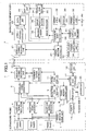
- Fig. 1 illustrates the configuration of an ultrasound diagnostic equipment according to Embodiment 1 of the invention.
- the ultrasound diagnostic equipment includes a rechargeable ultrasound probe 1 and a diagnostic equipment body 2 connected to the ultrasound probe 1 through wireless communication.
- the ultrasound probe 1 has a plurality of ultrasound transducers 3 which constitute a one-dimensional or two-dimensional transducer array.
- Reception signal processors 4 are correspondingly connected to the transducers 3, and a wireless communication unit 6 is connected to the reception signal processors 4 through a parallel/serial converter 5.
- a transmission controller 8 is connected to the plurality of transducers 3 through a transmission drive unit 7, a reception controller 9 is connected to the plurality of reception signal processors 4, and a communication controller 10 is connected to the wireless communication unit 6.
- a probe controller 11 is connected to the parallel/serial converter 5, the transmission controller 8, the reception controller 9, and the communication controller 10.
- Each of the plurality of transducers 3 transmits an ultrasonic wave in response to an actuation signal supplied from the transmission drive unit 7 and receives an ultrasonic echo from the subject, and outputs a reception signal.
- Each transducer 3 is constituted by a vibrator in which electrodes are formed at both ends of a piezoelectric body composed of, for example, piezoelectric ceramic represented by PZT (lead zirconate titanate), a polymer piezoelectric device represented by PVDF (polyvinylidene fluoride), or the like.
- the piezoelectric body expands and contracts, whereby pulsed or continuous-wave ultrasonic waves are produced from the respective vibrators and the produced ultrasonic waves are synthesized to form an ultrasonic beam.
- the respective vibrators expand and contract to produce electric signals, and the electric signals are output as the reception signals of the ultrasonic waves.
- the transmission drive unit 7 includes, for example, a plurality of pulse generators.
- the transmission drive unit 7 adjusts the delay amount of each of the actuation signals on the basis of a transmission delay pattern selected by the transmission controller 8 such that the ultrasonic waves transmitted from the plurality of transducers 3 form an ultrasonic beam having a width enough to cover the area of a tissue in the subject, and supplies the adjusted actuation signals to the plurality of transducers 3.
- the reception signal processor 4 of each channel performs quadrature detection processing or quadrature sampling processing on the reception signal output from the corresponding transducer 3 under the control of the reception controller 9 to produce a complex baseband signal, samples the complex baseband signal to produce sample data including information on the area of the tissue, and supplies the sample data to the parallel/serial converter 5.
- the reception signal processor 4 may perform data compression processing for low bit rate coding on data obtained by sampling the complex baseband signal to produce sample data.
- the parallel/serial converter 5 converts parallel sample data produced by the plurality of channels of reception signal processors 4 to serial sample data.
- the wireless communication unit 6 modulates a carrier on the basis of the serial sample data to produce a transmission signal, supplies the transmission signal to an antenna, and transmits a radio wave from the antenna, thereby transmitting the serial sample data.
- the modulation system for example, ASK (Amplitude Shift Keying), PSK (Phase Shift Keying), QPSK (Quadrature Phase Shift Keying), 16QAM (16 Quadrature Amplitude Modulation), or the like is used.
- the wireless communication unit 6 performs wireless communication with the diagnostic equipment body 2 to transmit the sample data to the diagnostic equipment body 2 and to receive various control signals from the diagnostic equipment body 2, and outputs the received control signals to the communication controller 10.
- the communication controller 10 controls the wireless communication unit 6 such that the sample data is transmitted with transmission radio field intensity set by the probe controller 11, and outputs various control signals received by the wireless communication unit 6 to the probe controller 11.
- the probe controller 11 controls the respective units of the ultrasound probe 1 on the basis of various control signals transmitted from the diagnostic apparatus body 2.
- the battery 13 functions as a power source of the ultrasound probe 1, and supplies power to the respective units, which require power, in the ultrasound probe 1.
- the battery controller 12 controls power supply from the battery 13 to the respective units in the ultrasound probe 1, monitors the residual amount of power of the battery 13, and each time the battery 13 is charged through the power receiver 14, updates the number of times of charging and stores the number of times of charging updated in the storage unit 16. Though described below, since the number of times of charging of the battery 13 stored in the storage unit 16 is reset to zero when refresh charging is executed, the number of times of successions of top-up charging is stored in the storage unit 16.
- the discharger 15 discharges the battery 13 on the basis of an instruction from the battery controller 12, and makes the residual amount of power zero.
- the ultrasound probe 1 may be an external probe, such as a linear scan type, a convex scan type, or a sector scan type, or may be a probe for an ultrasound endoscope, such as a radial scan type.
- the diagnostic equipment body 2 has a wireless communication unit 21.
- a data storage unit 23 is connected to the wireless communication unit 21 through a serial/parallel converter 22, and an image producer 24 is connected to the data storage unit 23.
- a display unit 26 is connected to the image producer 24 through a display controller 25.
- a communication controller 27 is connected to the wireless communication unit 21, and an equipment body controller 28 is connected to the serial/parallel converter 22, the image producer 24, the display controller 25, and the communication controller 27.
- An operating unit 29 for an input operation by an operator and a storage unit 30 which stores operation programs are respectively connected to the equipment body controller 28.
- a power source unit 32 is connected to the equipment body controller 28 through a power supply controller 31.
- a probe holder 33 which holds the ultrasound probe 1 not in use is formed in the diagnostic equipment body 2, and a power supply unit 34 is provided in the probe holder 33.
- the wireless communication unit 21 performs wireless communication with the ultrasound probe 1 to transmit various control signals to the ultrasound probe 1. Besides, the wireless communication unit 21 demodulates a signal received by an antenna to output serial sample data.
- the communication controller 27 controls the wireless communication unit 21 such that various control signals are transmitted with transmission radio field intensity set by the equipment body controller 28.
- the serial/parallel converter 22 converts the serial sample data output from the wireless communication unit 21 to parallel sample data.
- the data storage unit 23 is constituted by a memory, a hard disk, or the like, and stores the sample data for at least one frame converted by the serial/parallel converter 22.
- the image producer 24 performs reception focus processing on the sample data for every frame read from the data storage unit 23 to produce an image signal representing an ultrasound diagnostic image.
- the image producer 24 includes a phasing adder 35 and an image processor 36.
- the phasing adder 35 performs the reception focus processing by selecting one reception delay pattern from among a plurality of reception delay patterns stored in advance in accordance with a reception direction set in the equipment body controller 28, giving a delay to each of a plurality of complex baseband signals represented by the sample data on the basis of the selected reception delay pattern, and adding the reception signals. With this reception focus processing, the focus of the ultrasonic echo is narrowed to produce a baseband signal (sound ray signal).
- the image processor 36 produces a B-mode image signal, which is tomographic image information relating to a tissue in the subject, on the basis of the sound ray signal produced by the phasing adder 35.
- the image processor 36 includes an STC (sensitivity time control) unit and a DSC (digital scan converter).
- the STC unit corrects attenuation depending on the distance in accordance with the depth of the reflection position of the ultrasonic wave for the sound ray signal.
- the DSC converts (raster-converts) the sound ray signal corrected by the STC unit to an image signal based on a normal television signal scan system, and performs necessary image processing, such as gradation processing, to produce a B-mode image signal.
- the display controller 25 displays an ultrasound diagnostic image on the display unit 26 on the basis of the image signal produced by the image producer 24.
- the display unit 26 includes, for example, a display device, such as an LCD, and displays the ultrasound diagnostic image under the control of the display controller 25.
- the equipment body controller 28 controls the respective units in the diagnostic equipment body 2.
- the power source unit 32 supplies power to the respective units, which require power, in the diagnostic equipment body 2.
- the power supply controller 31 connects the power source unit 32 to the power supply unit 34 of the probe holder 33 as necessary on the basis of the examination situation in the diagnostic equipment body 2 input through the equipment body controller 28 and power supply information, such as the residual amount of power and the number of times of charging of the battery 13 transmitted from the ultrasound probe 1 through wireless communication, and causes the battery 13 of the ultrasound probe 1 to selectively perform refresh charging and top-up charging.
- the power supply unit 34 of the probe holder 33 supplies power to the power receiver 14 of the ultrasound probe 1 held in the probe holder 33 in a noncontact manner through electromagnetic induction or the like.
- the serial/parallel converter 22, the image producer 24, the display controller 25, the communication controller 27, the equipment body controller 28, and the power supply controller 31 are constituted by a CPU and operation programs which cause the CPU to perform various types of processing, these may be constituted by digital circuits.
- the operation programs are stored in the storage unit 30.
- a recording medium in the storage unit 30 in addition to an internal hard disk, a flexible disk, an MO, an MT, a RAM, a CD-ROM, a DVD-ROM, or the like may be used.
- Ultrasound diagnosis is performed in this way, and in the ultrasound probe 1, the residual amount of power of the battery 13 is monitored by the battery controller 12 and the number of times of charging of the battery 13 is stored in the storage unit 16.
- the power supply controller 31 of the diagnostic equipment body 2 can recognize the residual amount of power and the number of times of charging of the battery 13 through the equipment body controller 28 and the communication controller 27 by wireless communication. Further, the power supply controller 31 can recognize the examination situation in the diagnostic equipment body 2 through the equipment body controller 28.
- the ultrasound probe 1 is held in the probe holder 33 of the diagnostic equipment body 2.
- Step S1 the residual amount of power of the battery 13 is compared with a threshold value Eth set in advance.
- the threshold value Eth is used to decide whether or not it is necessary to charge the battery 13. If it is determined that the residual amount of power of the battery 13 falls below the threshold value Eth, the process progresses to Step S2, and it is determined whether or not it is a refresh charging timing from the examination situation in the diagnostic equipment body 2.
- Step S2 the timing at which it is foreseen that the ultrasound probe 1 is held in the probe holder 33 of the diagnostic apparatus body 2 over a predetermined time or more is detected as the refresh charging timing
- the examples of the timing include the cases where the examination for the day ends, a long vacant time is secured in the intervals between examinations, and the like. If it is determined in Step S2 that it is the refresh charging timing, in Step S3, it is further determined whether or not the number of times of charging of the battery 13 stored in the storage unit 16 of the ultrasound probe 1 reaches a predetermined threshold value Nth, for example, ten times.
- Nth for example, ten times.
- the number of times of charging stored in the storage unit 16 of the ultrasound probe 1 represents the number of successions of top-up charging of the battery 13, it is decided whether or not top-up charging of the battery 13 is performed successively, for example, ten times or more.
- Step S3 If it is determined in Step S3 that the number of times of charging of the battery 13 has reached the threshold value Nth, it is judged that refresh charging should be executed, and in Step S4, the battery 13 is discharged once by the discharger 15 through the battery controller 12 of the ultrasound probe 1 to make the residual amount of power zero. Thereafter, in Step S5, power is supplied from the power supply unit 34 of the probe holder 33 to the power receiver 14 of the ultrasound probe 1 held in the probe holder 33 in a noncontact manner through electromagnetic induction or the like, and the charging operation of the battery 13 is executed. The charging operation is continued until the residual amount of power of the battery 13 becomes a maximum value Ef representing full charging completion in the next Step S6. Thereby, refresh charging of the battery 13 is completed. If refresh charging is completed in this way, the number of times of charging stored in the storage unit 16 is reset to zero by the battery controller 12 of the ultrasound probe 1.
- Step S2 When it is determined in Step S2 that it is not the refresh charging timing and when it is determined in Step S3 that the number of times of charging of the battery 13 has not reached the threshold value Nth, it is judged that refresh charging should be not executed. In this case, the battery 13 is not discharged in Step S4, the process progresses to Step S5 directly, and the charging operation is performed. That is, top-up charging is executed. In this case, the number of times of charging stored in the storage unit 16 is incremented by "1" by the battery controller 12 of the ultrasound probe 1.
- the power supply controller 31 of the diagnostic equipment body 2 determines whether or not to perform refresh charging on the basis of the power supply information to the battery 13 and the examination situation in the diagnostic equipment body 2, a confirmation screen of refresh charging may be displayed on the display unit 26 of the diagnostic equipment body 2, and the operator may input an instruction for refresh charging while viewing the confirmation screen.
- a screen illustrated in Fig. 3 may be displayed, and one of buttons for refresh charging, shutdown, and cancel may be selected
- a screen illustrated in Fig. 4 may be displayed, and one of buttons for refresh charging, standby, and cancel may be selected.
- a button for refresh charging is selected, a screen illustrated in Fig. 5 may be displayed, and a button for execute charging may be selected to start the execution of refresh charging.
- a screen illustrated in Fig. 3 or 4 may be displayed, and the button for refresh charging may be grayed out to be not selectable, or only the button for refresh charging may not be displayed.
- the ultrasound diagnostic equipment may be constituted such that the ultrasound diagnostic equipment is started as necessary in the midstream of charging.
- Step S1 of Fig. 2 when it is determined that the residual amount of power of the battery 13 falls below the threshold value Eth set in advance, refresh charging or top-up charging is performed, in regard to top-up charging, the charging operation may be performed each time the ultrasound probe 1 is held in the probe holder 33.
- Step S4 the battery 13 is discharged by the discharger 15 through the battery controller 12 of the ultrasound probe 1, the invention is not limited thereto, and a battery discharging coil may be arranged in the probe holder 33 of the diagnostic equipment body 2 in advance, and the battery discharging coil may be driven to discharge the battery 13 of the ultrasound probe 1 held in the probe holder 33.
- the plurality of probe holders 33 are provided in the diagnostic equipment body 41, and a plurality of ultrasound probes 1 can be respectively held in the probe holders 33.
- the residual amount of power and the number of times of charging of the battery 13 of the ultrasound probe 1, and the use situation of the ultrasound probe 1 differ between the respective ultrasound probes 1.
- the power supply controller 31 of the diagnostic equipment body 41 performs the determination of the residual amount of power, the determination of the refresh charging timing, and the determination of the number of times of charging with respect to each battery 13 as illustrated in the flowchart of Fig. 2 , thereby as necessary, causing each battery 13 of the ultrasound probes 1 to selectively perform refresh charging and top-up charging using the power supply unit 34 of the respective probe holder 33.
- refresh charging is not permitted to start for the battery 13 of the ultrasound probe 1 set. Meanwhile, top-up charging is permitted. Accordingly, refresh charging is not performed for all of the necessary ultrasound probes 1 simultaneously, whereby it is possible to cope with an abrupt request to use an ultrasound diagnostic equipment.
- refresh charging does not start for the battery 13 of the ultrasound probe 1 set in the probe holder 33, display to the effect that refresh charging is not performed tentatively may be performed.
- the power supply controller 31 issues an instruction to each power supply unit 34 such that refresh charging is preferentially performed in a descending order of the number of times of charging, that is, in an order of the ultrasound probe A, the ultrasound probe B, and the ultrasound probe C. Accordingly, the ultrasound probe 1 in which refresh charging will be required is preferentially designated, thereby achieving improvement in operability.
- the power supply controller 31 may designate the ultrasound probe 1, in which refresh charging is preferentially performed, from among a plurality of ultrasound probes 1 on the basis of the previous examination situations of the battery 13 corresponding to the plurality of ultrasound probes 1 held in a plurality of probe holders 33.
- refresh charging of the battery 13 of the ultrasound probe 1 is performed in a descending order of use frequency on the basis of the examination situation representing history information of each ultrasound probe 1.
- the power supply controller 31 issues an instruction to each power supply unit 34 such that refresh charging is preferentially performed in an order of the ultrasound probe A, the ultrasound probe B, and the ultrasound probe C. Accordingly, the ultrasound probe 1 having the highest use frequency is preferentially designated from among the ultrasound probes 1 in which refresh charging will be required, thereby achieving improvement in operability.
- a plurality of ultrasound probes 1 corresponding to various diagnosis purposes selectively perform refresh charging and top-up charging depending on the residual amount of power of the battery, the number of times of charging of the battery, and the use situation, making it possible to charge the battery 13 of the ultrasound probe 1 while suppressing lowering in examination efficiency of ultrasound diagnosis.
- the number of times of charging of the battery 13 is stored as information stored in the storage unit 16
- the residual amount of power of the battery 13 monitored by the battery controller 12 may be stored.
- Examples 1 to 7 relating to the flow of an examination of specific ultrasound diagnosis and the timing at which top-up charging and refresh charging are performed will be described below. Operation of various buttons in Examples 1 to 7 is made through the operating unit 29. On the basis of an instruction input to the operating unit 29, the examination situation in the power supply controller 31 is determined through the equipment body controller 28.
Landscapes
- Health & Medical Sciences (AREA)
- Life Sciences & Earth Sciences (AREA)
- Engineering & Computer Science (AREA)
- Biomedical Technology (AREA)
- Medical Informatics (AREA)
- Veterinary Medicine (AREA)
- Public Health (AREA)
- Physics & Mathematics (AREA)
- General Health & Medical Sciences (AREA)
- Animal Behavior & Ethology (AREA)
- Biophysics (AREA)
- Nuclear Medicine, Radiotherapy & Molecular Imaging (AREA)
- Pathology (AREA)
- Radiology & Medical Imaging (AREA)
- Surgery (AREA)
- Heart & Thoracic Surgery (AREA)
- Molecular Biology (AREA)
- Chemical Kinetics & Catalysis (AREA)
- Manufacturing & Machinery (AREA)
- Chemical & Material Sciences (AREA)
- General Chemical & Material Sciences (AREA)
- Electrochemistry (AREA)
- Computer Networks & Wireless Communication (AREA)
- Gynecology & Obstetrics (AREA)
- Microelectronics & Electronic Packaging (AREA)
- Computer Vision & Pattern Recognition (AREA)
- Ultra Sonic Daignosis Equipment (AREA)
- Secondary Cells (AREA)
- Charge And Discharge Circuits For Batteries Or The Like (AREA)
Abstract
Description
- The present invention relates to an ultrasound diagnostic equipment, in particular, an ultrasound diagnostic equipment in which a rechargeable ultrasound probe with a built-in battery and a diagnostic equipment body are connected together in a wireless manner.
- An ultrasound diagnostic equipment using an ultrasound image has hitherto been put into practical use in the field of medicine. In general, this type of ultrasound diagnostic apparatus has an ultrasound probe with a built-in transducer array and a diagnostic equipment body connected to the ultrasound probe. In the ultrasound diagnostic apparatus, an ultrasonic wave is transmitted from the ultrasound probe toward a subject, an ultrasonic echo from the subject is received by the ultrasound probe, and the reception signals are electrically processed in the diagnostic equipment body to produce an ultrasound image.
- In recent years, an ultrasound diagnostic equipment has been developed in which the ultrasound probe and the diagnostic equipment body are connected through wireless communication in order to eliminate inconvenience of a communication cable which connects the ultrasound probe and the diagnostic equipment body, thereby improving operability. In this wireless ultrasound diagnostic equipment, for example, as described in
Patent Literature 1, the ultrasound probe has a battery built-in as a power source, and when charging of the battery is required, power is supplied from a power supply unit of the diagnostic equipment body to the battery of the ultrasound probe in a noncontact manner through electromagnetic induction or the like in a state where the ultrasound probe is stored in a probe holder provided in the diagnostic equipment body. - PATENT LITERATURE 1:
JP 2003-10177 A - In general, in a battery which is represented by a nickel-hydrogen battery or the like, if so-called top-up charging in which charging is performed before the residual amount of power of the battery becomes zero is frequently performed, it is noted that there is a problem in that the battery capacity is lowered due to the memory effect of the battery. In contrast with the top-up charging, if so-called refresh charging in which the battery is once discharged to make the residual amount of power zero and then charging is performed, is performed regularly, it is possible to extend the battery life.
However, since refresh charging takes a long period of time, the actual situation is that it is not easy to perform refresh charging of the battery built in to the ultrasound probe without causing a problem in an examination using the ultrasound diagnostic equipment. - The invention has been accomplished in order to solve the drawbacks in the prior art, and an object of the invention is to provide an ultrasound diagnostic equipment which is able to charge a battery of a rechargeable ultrasound probe while suppressing lowering in examination efficiency.
- An ultrasound diagnostic equipment according to the present invention is an equipment in which a rechargeable ultrasound probe with a built-in battery and a diagnostic equipment body are connected together in a wireless manner, an ultrasonic beam is transmitted from a transducer array of the ultrasound probe toward a subject, and the diagnostic equipment body produces an ultrasound image on the basis of reception signals output from the transducer array of the ultrasound probe having received an ultrasonic echo from the subject, wherein the diagnostic equipment body includes a power supply unit which supplies power to the battery of the ultrasound probe, and a power supply controller which causes the battery of the ultrasound probe to selectively perform refresh charging and top-up charging using the power supply unit on the basis of power supply information to the battery of the ultrasound probe and the examination situation in the diagnostic equipment body.
- It is preferable that the ultrasound probe has a storage unit which stores the power supply information.
It may be constructed that the diagnostic equipment body includes a probe holder which holds the ultrasound probe, and the power supply unit supplies power to the battery of the ultrasound probe held in the probe holder.
Further, it also may be constructed such that the diagnostic equipment body includes a plurality of probe holders, the power supply unit supplies power separately to the batteries of a plurality of ultrasound probes held in the plurality of probe holders, and the power supply controller causes the batteries of the plurality of ultrasound probes held in the plurality of probe holders to selectively perform refresh charging and top-up charging using the power supply unit on the basis of the corresponding power supply information and the examination situation. - In this case, the power supply controller may determine whether or not refresh charging is possible in the batteries of the plurality of ultrasound probes on the basis of the types of the plurality of ultrasound probes held in the plurality of probe holders and the power supply information corresponding to the batteries of the plurality of ultrasound probes.
The power supply controller may designate an ultrasound probe, in which refresh charging is preferentially performed, from among the plurality of ultrasound probes on the basis of the power supply information corresponding to the batteries of the plurality of ultrasound probes held in the plurality of probe holders. Further, the power supply controller may designate an ultrasound probe, in which refresh charging is preferentially performed, from among the plurality of ultrasound probes on the basis of the examination situations corresponding to the batteries of the plurality of ultrasound probes held in the plurality of probe holders. - According to the invention, the power supply controller of the diagnostic equipment body causes the battery of the ultrasound probe to selectively perform refresh charging and top-up charging using the power supply unit on the basis of the power supply information to the battery of the rechargeable ultrasound probe and the examination situation in the diagnostic equipment body, making it possible to charge the battery of the ultrasound probe while suppressing lowering in examination efficiency.
-
-
Fig. 1 is a block diagram illustrating the configuration of an ultrasound diagnostic equipment according toEmbodiment 1 of the invention. -
Fig. 2 is a flowchart illustrating an operation of a power supply controller inEmbodiment 1. -
Fig. 3 is a diagram illustrating screen display during shutdown in a modification ofEmbodiment 1. -
Fig. 4 is a diagram illustrating screen display during standby in the modification ofEmbodiment 1. -
Fig. 5 is a diagram illustrating screen display during refresh charging in the modification ofEmbodiment 1. -
Fig. 6 is a block diagram illustrating the configuration of a diagnostic equipment body used in an ultrasound diagnostic equipment according toEmbodiment 2. - Hereinafter, embodiments of the invention will be described with reference to the accompanying drawings.
-
Fig. 1 illustrates the configuration of an ultrasound diagnostic equipment according toEmbodiment 1 of the invention. The ultrasound diagnostic equipment includes arechargeable ultrasound probe 1 and adiagnostic equipment body 2 connected to theultrasound probe 1 through wireless communication. - The
ultrasound probe 1 has a plurality ofultrasound transducers 3 which constitute a one-dimensional or two-dimensional transducer array.Reception signal processors 4 are correspondingly connected to thetransducers 3, and awireless communication unit 6 is connected to thereception signal processors 4 through a parallel/serial converter 5. Atransmission controller 8 is connected to the plurality oftransducers 3 through atransmission drive unit 7, areception controller 9 is connected to the plurality ofreception signal processors 4, and acommunication controller 10 is connected to thewireless communication unit 6. Aprobe controller 11 is connected to the parallel/serial converter 5, thetransmission controller 8, thereception controller 9, and thecommunication controller 10.
Moreover, abattery 13 is connected to theprobe controller 11 through abattery controller 12, and apower receiver 14 for charging and adischarger 15 for discharging are connected to thebattery 13, and thedischarger 15 is connected to thebattery controller 12. Astorage unit 16 is connected to thebattery controller 12. - Each of the plurality of
transducers 3 transmits an ultrasonic wave in response to an actuation signal supplied from thetransmission drive unit 7 and receives an ultrasonic echo from the subject, and outputs a reception signal. Eachtransducer 3 is constituted by a vibrator in which electrodes are formed at both ends of a piezoelectric body composed of, for example, piezoelectric ceramic represented by PZT (lead zirconate titanate), a polymer piezoelectric device represented by PVDF (polyvinylidene fluoride), or the like.
If a pulsed or continuous-wave voltage is applied across the electrodes of the vibrator, the piezoelectric body expands and contracts, whereby pulsed or continuous-wave ultrasonic waves are produced from the respective vibrators and the produced ultrasonic waves are synthesized to form an ultrasonic beam. When receiving propagating ultrasonic waves, the respective vibrators expand and contract to produce electric signals, and the electric signals are output as the reception signals of the ultrasonic waves. - The
transmission drive unit 7 includes, for example, a plurality of pulse generators. Thetransmission drive unit 7 adjusts the delay amount of each of the actuation signals on the basis of a transmission delay pattern selected by thetransmission controller 8 such that the ultrasonic waves transmitted from the plurality oftransducers 3 form an ultrasonic beam having a width enough to cover the area of a tissue in the subject, and supplies the adjusted actuation signals to the plurality oftransducers 3. - The
reception signal processor 4 of each channel performs quadrature detection processing or quadrature sampling processing on the reception signal output from thecorresponding transducer 3 under the control of thereception controller 9 to produce a complex baseband signal, samples the complex baseband signal to produce sample data including information on the area of the tissue, and supplies the sample data to the parallel/serial converter 5. Thereception signal processor 4 may perform data compression processing for low bit rate coding on data obtained by sampling the complex baseband signal to produce sample data.
The parallel/serial converter 5 converts parallel sample data produced by the plurality of channels ofreception signal processors 4 to serial sample data. - The
wireless communication unit 6 modulates a carrier on the basis of the serial sample data to produce a transmission signal, supplies the transmission signal to an antenna, and transmits a radio wave from the antenna, thereby transmitting the serial sample data. As the modulation system, for example, ASK (Amplitude Shift Keying), PSK (Phase Shift Keying), QPSK (Quadrature Phase Shift Keying), 16QAM (16 Quadrature Amplitude Modulation), or the like is used.
Thewireless communication unit 6 performs wireless communication with thediagnostic equipment body 2 to transmit the sample data to thediagnostic equipment body 2 and to receive various control signals from thediagnostic equipment body 2, and outputs the received control signals to thecommunication controller 10. Thecommunication controller 10 controls thewireless communication unit 6 such that the sample data is transmitted with transmission radio field intensity set by theprobe controller 11, and outputs various control signals received by thewireless communication unit 6 to theprobe controller 11. - The
probe controller 11 controls the respective units of theultrasound probe 1 on the basis of various control signals transmitted from thediagnostic apparatus body 2.
Thebattery 13 functions as a power source of theultrasound probe 1, and supplies power to the respective units, which require power, in theultrasound probe 1. Thebattery controller 12 controls power supply from thebattery 13 to the respective units in theultrasound probe 1, monitors the residual amount of power of thebattery 13, and each time thebattery 13 is charged through thepower receiver 14, updates the number of times of charging and stores the number of times of charging updated in thestorage unit 16. Though described below, since the number of times of charging of thebattery 13 stored in thestorage unit 16 is reset to zero when refresh charging is executed, the number of times of successions of top-up charging is stored in thestorage unit 16. Thedischarger 15 discharges thebattery 13 on the basis of an instruction from thebattery controller 12, and makes the residual amount of power zero.
Theultrasound probe 1 may be an external probe, such as a linear scan type, a convex scan type, or a sector scan type, or may be a probe for an ultrasound endoscope, such as a radial scan type. - The
diagnostic equipment body 2 has awireless communication unit 21. Adata storage unit 23 is connected to thewireless communication unit 21 through a serial/parallel converter 22, and animage producer 24 is connected to thedata storage unit 23. Adisplay unit 26 is connected to theimage producer 24 through adisplay controller 25. Acommunication controller 27 is connected to thewireless communication unit 21, and anequipment body controller 28 is connected to the serial/parallel converter 22, theimage producer 24, thedisplay controller 25, and thecommunication controller 27. An operatingunit 29 for an input operation by an operator and astorage unit 30 which stores operation programs are respectively connected to theequipment body controller 28.
Further, apower source unit 32 is connected to theequipment body controller 28 through apower supply controller 31. Aprobe holder 33 which holds theultrasound probe 1 not in use is formed in thediagnostic equipment body 2, and apower supply unit 34 is provided in theprobe holder 33. - The
wireless communication unit 21 performs wireless communication with theultrasound probe 1 to transmit various control signals to theultrasound probe 1. Besides, thewireless communication unit 21 demodulates a signal received by an antenna to output serial sample data.
Thecommunication controller 27 controls thewireless communication unit 21 such that various control signals are transmitted with transmission radio field intensity set by theequipment body controller 28.
The serial/parallel converter 22 converts the serial sample data output from thewireless communication unit 21 to parallel sample data. Thedata storage unit 23 is constituted by a memory, a hard disk, or the like, and stores the sample data for at least one frame converted by the serial/parallel converter 22. - The
image producer 24 performs reception focus processing on the sample data for every frame read from thedata storage unit 23 to produce an image signal representing an ultrasound diagnostic image. Theimage producer 24 includes a phasingadder 35 and animage processor 36.
The phasingadder 35 performs the reception focus processing by selecting one reception delay pattern from among a plurality of reception delay patterns stored in advance in accordance with a reception direction set in theequipment body controller 28, giving a delay to each of a plurality of complex baseband signals represented by the sample data on the basis of the selected reception delay pattern, and adding the reception signals. With this reception focus processing, the focus of the ultrasonic echo is narrowed to produce a baseband signal (sound ray signal). - The
image processor 36 produces a B-mode image signal, which is tomographic image information relating to a tissue in the subject, on the basis of the sound ray signal produced by the phasingadder 35. Theimage processor 36 includes an STC (sensitivity time control) unit and a DSC (digital scan converter). The STC unit corrects attenuation depending on the distance in accordance with the depth of the reflection position of the ultrasonic wave for the sound ray signal. The DSC converts (raster-converts) the sound ray signal corrected by the STC unit to an image signal based on a normal television signal scan system, and performs necessary image processing, such as gradation processing, to produce a B-mode image signal.
Thedisplay controller 25 displays an ultrasound diagnostic image on thedisplay unit 26 on the basis of the image signal produced by theimage producer 24. Thedisplay unit 26 includes, for example, a display device, such as an LCD, and displays the ultrasound diagnostic image under the control of thedisplay controller 25. - The
equipment body controller 28 controls the respective units in thediagnostic equipment body 2.
Thepower source unit 32 supplies power to the respective units, which require power, in thediagnostic equipment body 2. Thepower supply controller 31 connects thepower source unit 32 to thepower supply unit 34 of theprobe holder 33 as necessary on the basis of the examination situation in thediagnostic equipment body 2 input through theequipment body controller 28 and power supply information, such as the residual amount of power and the number of times of charging of thebattery 13 transmitted from theultrasound probe 1 through wireless communication, and causes thebattery 13 of theultrasound probe 1 to selectively perform refresh charging and top-up charging. Thepower supply unit 34 of theprobe holder 33 supplies power to thepower receiver 14 of theultrasound probe 1 held in theprobe holder 33 in a noncontact manner through electromagnetic induction or the like. - Although in the
diagnostic equipment body 2, the serial/parallel converter 22, theimage producer 24, thedisplay controller 25, thecommunication controller 27, theequipment body controller 28, and thepower supply controller 31 are constituted by a CPU and operation programs which cause the CPU to perform various types of processing, these may be constituted by digital circuits. The operation programs are stored in thestorage unit 30. As a recording medium in thestorage unit 30, in addition to an internal hard disk, a flexible disk, an MO, an MT, a RAM, a CD-ROM, a DVD-ROM, or the like may be used. - During diagnosis, first, ultrasonic waves are transmitted from the plurality of
transducers 3 in accordance with the actuation signals supplied from thetransmission drive unit 7 of theultrasound probe 1, and the reception signal output from eachtransducer 3 having received the ultrasonic echo from the subject is supplied to the correspondingreception signal processor 4 to produce sample data. The sample data is converted to serial sample data by the parallel/serial converter 5, and the serial sample data is transmitted from thewireless communication unit 6 to thediagnostic equipment body 2 in a wireless manner. The sample data received by thewireless communication unit 21 of thediagnostic equipment body 2 is converted to parallel sample data by the serial/parallel converter 22, and the parallel sample data is stored in thedata storage unit 23. The sample data for every frame is read from thedata storage unit 23, an image signal is produced by theimage producer 24, and an ultrasound diagnostic image is displayed on thedisplay unit 26 on the basis of the image signal by thedisplay controller 25. - Ultrasound diagnosis is performed in this way, and in the
ultrasound probe 1, the residual amount of power of thebattery 13 is monitored by thebattery controller 12 and the number of times of charging of thebattery 13 is stored in thestorage unit 16. Thepower supply controller 31 of thediagnostic equipment body 2 can recognize the residual amount of power and the number of times of charging of thebattery 13 through theequipment body controller 28 and thecommunication controller 27 by wireless communication. Further, thepower supply controller 31 can recognize the examination situation in thediagnostic equipment body 2 through theequipment body controller 28. When theultrasound probe 1 is not used, theultrasound probe 1 is held in theprobe holder 33 of thediagnostic equipment body 2. - Here, the operation of the
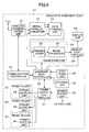
power supply controller 31 of thediagnostic equipment body 2 will be described with reference to the flowchart ofFig. 2 .
First, in Step S1, the residual amount of power of thebattery 13 is compared with a threshold value Eth set in advance. The threshold value Eth is used to decide whether or not it is necessary to charge thebattery 13. If it is determined that the residual amount of power of thebattery 13 falls below the threshold value Eth, the process progresses to Step S2, and it is determined whether or not it is a refresh charging timing from the examination situation in thediagnostic equipment body 2. - In general, since refresh charging requires a long period of time, the timing at which it is foreseen that the
ultrasound probe 1 is held in theprobe holder 33 of thediagnostic apparatus body 2 over a predetermined time or more is detected as the refresh charging timing, and the examples of the timing include the cases where the examination for the day ends, a long vacant time is secured in the intervals between examinations, and the like.
If it is determined in Step S2 that it is the refresh charging timing, in Step S3, it is further determined whether or not the number of times of charging of thebattery 13 stored in thestorage unit 16 of theultrasound probe 1 reaches a predetermined threshold value Nth, for example, ten times. As described above, since the number of times of charging stored in thestorage unit 16 of theultrasound probe 1 represents the number of successions of top-up charging of thebattery 13, it is decided whether or not top-up charging of thebattery 13 is performed successively, for example, ten times or more. - If it is determined in Step S3 that the number of times of charging of the
battery 13 has reached the threshold value Nth, it is judged that refresh charging should be executed, and in Step S4, thebattery 13 is discharged once by thedischarger 15 through thebattery controller 12 of theultrasound probe 1 to make the residual amount of power zero. Thereafter, in Step S5, power is supplied from thepower supply unit 34 of theprobe holder 33 to thepower receiver 14 of theultrasound probe 1 held in theprobe holder 33 in a noncontact manner through electromagnetic induction or the like, and the charging operation of thebattery 13 is executed. The charging operation is continued until the residual amount of power of thebattery 13 becomes a maximum value Ef representing full charging completion in the next Step S6. Thereby, refresh charging of thebattery 13 is completed.
If refresh charging is completed in this way, the number of times of charging stored in thestorage unit 16 is reset to zero by thebattery controller 12 of theultrasound probe 1. - When it is determined in Step S2 that it is not the refresh charging timing and when it is determined in Step S3 that the number of times of charging of the
battery 13 has not reached the threshold value Nth, it is judged that refresh charging should be not executed. In this case, thebattery 13 is not discharged in Step S4, the process progresses to Step S5 directly, and the charging operation is performed. That is, top-up charging is executed.
In this case, the number of times of charging stored in thestorage unit 16 is incremented by "1" by thebattery controller 12 of theultrasound probe 1. - As described above, according to
Embodiment 1, when it is necessary to charge thebattery 13 of theultrasound probe 1, thepower supply controller 31 of thediagnostic equipment body 2 causes thebattery 13 of theultrasound probe 1 to selectively perform refresh charging and top-up charging by thepower supply unit 34 of theprobe holder 33 on the basis of the power supply information to thebattery 13 and the examination situation in thediagnostic apparatus body 2. Therefore, it becomes possible to charge thebattery 13 of theultrasound probe 1 while suppressing lowering in examination efficiency. - Although in
Embodiment 1, thepower supply controller 31 of thediagnostic equipment body 2 determines whether or not to perform refresh charging on the basis of the power supply information to thebattery 13 and the examination situation in thediagnostic equipment body 2, a confirmation screen of refresh charging may be displayed on thedisplay unit 26 of thediagnostic equipment body 2, and the operator may input an instruction for refresh charging while viewing the confirmation screen. For example, during shutdown of the equipment, a screen illustrated inFig. 3 may be displayed, and one of buttons for refresh charging, shutdown, and cancel may be selected, or during standby of the equipment, a screen illustrated inFig. 4 may be displayed, and one of buttons for refresh charging, standby, and cancel may be selected. When the button for refresh charging is selected, a screen illustrated inFig. 5 may be displayed, and a button for execute charging may be selected to start the execution of refresh charging. - Even when the
power supply controller 31 of thediagnostic equipment body 2 determines that refresh charging should not be executed on the basis of the power supply information to thebattery 13 and the examination situation in thediagnostic equipment body 2, a screen illustrated inFig. 3 or4 may be displayed, and the button for refresh charging may be grayed out to be not selectable, or only the button for refresh charging may not be displayed.
Even when the button of the equipment is long pressed to turn off power, for example, when the equipment will be restarted due to starting failure, or the like, it is possible to set whether or not to perform refresh charging.
Further, even in the case where refresh charging is executed when the equipment is shutdown, the ultrasound diagnostic equipment may be constituted such that the ultrasound diagnostic equipment is started as necessary in the midstream of charging. - Although in
Embodiment 1, in Step S1 ofFig. 2 , when it is determined that the residual amount of power of thebattery 13 falls below the threshold value Eth set in advance, refresh charging or top-up charging is performed, in regard to top-up charging, the charging operation may be performed each time theultrasound probe 1 is held in theprobe holder 33.
Although in Step S4, thebattery 13 is discharged by thedischarger 15 through thebattery controller 12 of theultrasound probe 1, the invention is not limited thereto, and a battery discharging coil may be arranged in theprobe holder 33 of thediagnostic equipment body 2 in advance, and the battery discharging coil may be driven to discharge thebattery 13 of theultrasound probe 1 held in theprobe holder 33. -
Fig. 6 illustrates the configuration of adiagnostic equipment body 41 used in an ultrasound diagnostic equipment according toEmbodiment 2. Thediagnostic equipment body 41 includes a plurality ofprobe holders 33 each having thepower supply unit 34, and eachpower supply unit 34 is connected to thepower supply controller 31. Other parts are the same as thediagnostic equipment body 2 inEmbodiment 1 illustrated inFig. 1 . - In general, in ultrasound diagnosis, an appropriate ultrasound probe is selected in accordance with a region to be examined, the body shape of the subject, or the like. A scanning mode probe corresponding to a region to be examined may be used, or a probe having a different width due to a difference in an examination purpose may be selected for the same region to be examined. If an ultrasound probe is selected once and scanning starts, rarely switched to any of other ultrasound probes often to perform scanning, and even when candidates of a plurality of ultrasound probes are extracted prior to an examination, the ultrasound probes other than an ultrasound probe to be actually used can continue to be charged.
- Accordingly, in the ultrasound diagnostic equipment according to
Embodiment 2, the plurality ofprobe holders 33 are provided in thediagnostic equipment body 41, and a plurality ofultrasound probes 1 can be respectively held in theprobe holders 33. The residual amount of power and the number of times of charging of thebattery 13 of theultrasound probe 1, and the use situation of theultrasound probe 1 differ between the respective ultrasound probes 1. For this reason, for the plurality ofultrasound probes 1 held in the plurality ofprobe holders 33, thepower supply controller 31 of thediagnostic equipment body 41 performs the determination of the residual amount of power, the determination of the refresh charging timing, and the determination of the number of times of charging with respect to eachbattery 13 as illustrated in the flowchart ofFig. 2 , thereby as necessary, causing eachbattery 13 of the ultrasound probes 1 to selectively perform refresh charging and top-up charging using thepower supply unit 34 of therespective probe holder 33. - At this time, the
power supply controller 31 may determine whether or not refresh charging is possible in thebatteries 13 of the ultrasound probes 1 on the basis of the types of the plurality ofultrasound probes 1 held in the plurality ofprobe holders 33 and the power supply information corresponding to thebatteries 13 of the plurality of ultrasound probes 1.
When a plurality ofultrasound probes 1 of the same type are used, it is possible to prevent simultaneous refresh charging in all of the plurality of ultrasound probes 1. For example, when two linear scan type probes are used together and if refresh charging is in midstream for one linear scan type probe, in regard to the other one linear scan type probe, even when the number of times of charging of thebattery 13 exceeds the threshold value Nth, it is regulated such that refresh charging is not performed. - Specifically, even when it is recognized on the basis of the power supply information received from the
ultrasound probe 1 that afurther ultrasound probe 1 of the same type is set in anempty probe holder 33 of thediagnostic equipment body 41, refresh charging is not permitted to start for thebattery 13 of theultrasound probe 1 set. Meanwhile, top-up charging is permitted. Accordingly, refresh charging is not performed for all of the necessary ultrasound probes 1 simultaneously, whereby it is possible to cope with an abrupt request to use an ultrasound diagnostic equipment. When refresh charging does not start for thebattery 13 of theultrasound probe 1 set in theprobe holder 33, display to the effect that refresh charging is not performed tentatively may be performed. - The
power supply controller 31 may designate theultrasound probe 1, in which refresh charging is preferentially performed, from among a plurality ofultrasound probes 1 held in the plurality ofprobe holders 33 on the basis of the power supply information corresponding to thebatteries 13 of the plurality of ultrasound probes 1.
When there is a plurality ofultrasound probes 1 in which the number of times of charging of thebattery 13 has reached the predetermined threshold value Nth, refresh charging of thebattery 13 of theultrasound probe 1 is performed in a descending order of the number of times of charging. For example, in regard to three ultrasound probes A to C, when the number of times of charging of thebattery 13 of the ultrasound probe A is 20, the number of times of charging of thebattery 13 of the ultrasound probe B is 15, and the number of times of charging of thebattery 13 of the ultrasound probe C is 12, thepower supply controller 31 issues an instruction to eachpower supply unit 34 such that refresh charging is preferentially performed in a descending order of the number of times of charging, that is, in an order of the ultrasound probe A, the ultrasound probe B, and the ultrasound probe C. Accordingly, theultrasound probe 1 in which refresh charging will be required is preferentially designated, thereby achieving improvement in operability. - Further, the
power supply controller 31 may designate theultrasound probe 1, in which refresh charging is preferentially performed, from among a plurality of ultrasound probes 1 on the basis of the previous examination situations of thebattery 13 corresponding to the plurality ofultrasound probes 1 held in a plurality ofprobe holders 33.
When a plurality ofultrasound probes 1 in which the number of times of charging of thebattery 13 has reached the predetermined threshold value Nth, refresh charging of thebattery 13 of theultrasound probe 1 is performed in a descending order of use frequency on the basis of the examination situation representing history information of eachultrasound probe 1. For example, in regard to three ultrasound probes A to C, thepower supply controller 31 issues an instruction to eachpower supply unit 34 such that refresh charging is preferentially performed in an order of the ultrasound probe A, the ultrasound probe B, and the ultrasound probe C. Accordingly, theultrasound probe 1 having the highest use frequency is preferentially designated from among the ultrasound probes 1 in which refresh charging will be required, thereby achieving improvement in operability. - In this way, a plurality of
ultrasound probes 1 corresponding to various diagnosis purposes selectively perform refresh charging and top-up charging depending on the residual amount of power of the battery, the number of times of charging of the battery, and the use situation, making it possible to charge thebattery 13 of theultrasound probe 1 while suppressing lowering in examination efficiency of ultrasound diagnosis.
Although in the foregoing embodiments, an example where the number of times of charging of thebattery 13 is stored as information stored in thestorage unit 16 has been described, not only the number of times of charging of thebattery 13, but also the residual amount of power of thebattery 13 monitored by thebattery controller 12 may be stored. - Examples 1 to 7 relating to the flow of an examination of specific ultrasound diagnosis and the timing at which top-up charging and refresh charging are performed will be described below.
Operation of various buttons in Examples 1 to 7 is made through the operatingunit 29. On the basis of an instruction input to the operatingunit 29, the examination situation in thepower supply controller 31 is determined through theequipment body controller 28. - [A case where the result report, charting, and the like are made after image diagnosis is first performed]
An examination is performed alongSteps 1 to 8. - 1. A patient information input button "New Patient" is pressed.
- 2. A screen for inputting patient information is displayed and patient information is input.
- 3. An "Exit" button is pressed to start the examination.
- 4. Scanning by the ultrasound probe is performed.
- 5. An "End Exam" button is pressed to end the examination.
- 6. The result report or the like is made.
- 7. Explanation to the patient and charting are made.
- 8. The next patient is called and the "New Patient" button is pressed.
- An examination is performed along
Steps 1 to 14. - 1. The patient information input button "New Patient" is pressed.
- 2. A screen for inputting patient information is displayed and patient information is input.
- 3. The "Exit" button is pressed to start the examination.
- 4. A "Freeze" button is pressed to start a medical inquiry. At this time, an aerial emission state from the ultrasound probe may be detected, and freeze may be automatically made.
- 5. The patient makes preparations, such as change of clothes, so as to receive an examination.
- 6. The patient notifies a physician or technician that the preparations are completed.
- 7. The "Freeze" button is pressed again to release freeze.
- 8. Scanning by the ultrasound probe is performed.
- 9. The "End Exam" button is pressed to end the examination.
- 10. The "Freeze" button is pressed to make freeze. The setting may be made such that the freeze state is reached after the "End Exam" button is pressed. An aerial emission state from the ultrasound probe may be detected, and freeze may be automatically made.
- 11. It waits until the change of clothes or the like of the patient is completed.
- 12. The result report or the like is made.
- 13. Explanation to the patient and charting are made.
- 14. The next patient is called and "New Patient" is pressed.
- An examination is performed along
Steps 1 to 10. - 1. The patient information input button "New Patient" is pressed.
- 2. A screen for inputting patient information is displayed and patient information is input.
- 3. A "Worklist" button is pressed to call up the chart of the patient to be examined, and the "Exit" button is pressed to progress an examination screen.
- 4. The "Freeze" button is pressed, the patient is called, and a previous result report, a medical inquiry, or the like is made.
- 5. The patient makes preparations, such as change of clothes, so as to receive an examination.
- 6. The "Freeze" button is pressed again to release freeze.
- 7. Scanning by the ultrasound probe is performed.
- 8. The "End Exam" button is pressed to end the examination.
- 9. Explanation to the patient and charting are made.
- 10. The patient information input button "New Patient" is pressed for the next patient.
- An examination is performed along
Steps 1 to 2. - 1. Scanning by the ultrasound probe is performed.
- 2. The "End Exam" button is pressed to end the examination.
- An examination is performed along
Steps 1 to 3. - 1. A preset for first aid or emergency is selected.
- 2. Scanning by the ultrasound probe is performed.
- 3. The "End Exam" button is pressed to end the examination.
- An examination is performed along
Steps 1 to 8. - 1. The patient information input button "New Patient" is pressed.
- 2. A screen for inputting patient information is displayed and patient information is input.
- 3. The "Exit" button is pressed to start the examination. Here, the first ultrasound probe which is used for the examination is selected.
- 4. Scanning by the first ultrasound probe is performed.
- 5. The "End Exam" button is pressed to end the examination.
- 6. The result report or the like is made.
- 7. Explanation to the patient and charting are made.
- 8. The next patient is called and the "New Patient" button is pressed.
- An examination is performed along
Steps 1 to 8. - 1. The patient information input button "New Patient" is pressed.
- 2. A screen for inputting patient information is displayed and patient information is input.
- 3. The "Exit" button is pressed to start the examination.
Here, the first ultrasound probe to be first used is selected. - 4. Scanning by the first ultrasound probe is performed.
- 5. The second ultrasound probe to be next used is selected.
- 6. The operation of the first ultrasound probe is temporarily stopped.
- 7. Scanning by the second ultrasound probe is performed.
- 8. The "End Exam" button is pressed to end the examination.
- 9. The result report or the like is made.
- 10. Explanation to the patient and charting are made.
- 11. The next patient is called and the "New Patient" button is pressed.
- 1 ultrasound probe; 2, 41 diagnostic equipment body; 3 transducer; 4 reception signal processor; 5 parallel/serial converter; 6 wireless communication unit; 7 transmission drive unit; 8 transmission controller; 9 reception controller; 10 communication controller; 11 probe controller; 12 battery controller; 13 battery; 14 power receiver; 15 discharger; 16 storage unit; 21 wireless communication unit; 22 serial/parallel converter; 23 data storage unit; 24 image producer; 25 display controller; 26 display unit; 27 communication controller; 28 equipment body controller; 29 operating unit; 30 storage unit; 31 power supply controller; 32 power source unit; 33 probe holder; 34 power supply unit; 35 phasing adder; 36 image processor.
Claims (7)
- An ultrasound diagnostic equipment in which a rechargeable ultrasound probe with a built-in battery and a diagnostic equipment body are connected together in a wireless manner, an ultrasonic beam is transmitted from a transducer array of the ultrasound probe toward a subject, and the diagnostic equipment body produces an ultrasound image on the basis of reception signals output from the transducer array of the ultrasound probe having received an ultrasonic echo from the subject,
wherein the diagnostic equipment body includes
a power supply unit which supplies power to the battery of the ultrasound probe, and
a power supply controller which causes the battery of the ultrasound probe to selectively perform refresh charging and top-up charging using the power supply unit on the basis of power supply information to the battery of the ultrasound probe and the examination situation in the diagnostic equipment body. - The ultrasound diagnostic equipment according to claim 1, wherein the ultrasound probe has a storage unit which stores the power supply information.
- The ultrasound diagnostic equipment according to claim 1 or 2,
wherein the diagnostic equipment body includes a probe holder which holds the ultrasound probe, and
the power supply unit supplies power to the battery of the ultrasound probe held in the probe holder. - The ultrasound diagnostic equipment according to claim 3, wherein the diagnostic equipment body includes a plurality of probe holders,
the power supply unit supplies power separately to the batteries of a plurality of ultrasound probes held in the plurality of probe holders, and
the power supply controller causes the batteries of the plurality of ultrasound probes held in the plurality of probe holders to selectively perform refresh charging and top-up charging using the power supply unit on the basis of the corresponding power supply information and the examination situation. - The ultrasound diagnostic equipment according to claim 4, wherein the power supply controller determines whether or not refresh charging is possible in the batteries of the plurality of ultrasound probes on the basis of the types of the plurality of ultrasound probes held in the plurality of probe holders and the power supply information corresponding to the batteries of the plurality of ultrasound probes.
- The ultrasound diagnostic equipment according to claim 4 or 5,
wherein the power supply controller designates an ultrasound probe, in which refresh charging is preferentially performed, from among the plurality of ultrasound probes on the basis of the power supply information corresponding to the batteries of the plurality of ultrasound probes held in the plurality of probe holders. - The ultrasound diagnostic equipment according to any one of claims 4 to 6,
wherein the power supply controller designates an ultrasound probe, in which refresh charging is preferentially performed, from among the plurality of ultrasound probes on the basis of the examination situations corresponding to the batteries of the plurality of ultrasound probes held in the plurality of probe holders.
Applications Claiming Priority (3)
| Application Number | Priority Date | Filing Date | Title |
|---|---|---|---|
| JP2010203121 | 2010-09-10 | ||
| JP2011188838A JP5647957B2 (en) | 2010-09-10 | 2011-08-31 | Ultrasonic diagnostic equipment |
| PCT/JP2011/070267 WO2012033093A1 (en) | 2010-09-10 | 2011-09-06 | Ultrasound diagnostic equipment |
Publications (3)
| Publication Number | Publication Date |
|---|---|
| EP2614776A1 true EP2614776A1 (en) | 2013-07-17 |
| EP2614776A4 EP2614776A4 (en) | 2017-07-12 |
| EP2614776B1 EP2614776B1 (en) | 2019-08-28 |
Family
ID=45810691
Family Applications (1)
| Application Number | Title | Priority Date | Filing Date |
|---|---|---|---|
| EP11823568.8A Active EP2614776B1 (en) | 2010-09-10 | 2011-09-06 | Ultrasound diagnostic equipment |
Country Status (5)
| Country | Link |
|---|---|
| US (1) | US10105124B2 (en) |
| EP (1) | EP2614776B1 (en) |
| JP (1) | JP5647957B2 (en) |
| CN (1) | CN103096808B (en) |
| WO (1) | WO2012033093A1 (en) |
Families Citing this family (34)
| Publication number | Priority date | Publication date | Assignee | Title |
|---|---|---|---|---|
| US9339256B2 (en) | 2007-10-01 | 2016-05-17 | Maui Imaging, Inc. | Determining material stiffness using multiple aperture ultrasound |
| US9247926B2 (en) | 2010-04-14 | 2016-02-02 | Maui Imaging, Inc. | Concave ultrasound transducers and 3D arrays |
| JP6407719B2 (en) | 2011-12-01 | 2018-10-17 | マウイ イマギング,インコーポレーテッド | Motion detection using ping base and multi-aperture Doppler ultrasound |
| EP2833791B1 (en) | 2012-03-26 | 2022-12-21 | Maui Imaging, Inc. | Methods for improving ultrasound image quality by applying weighting factors |
| CN104620128B (en) | 2012-08-10 | 2017-06-23 | 毛伊图像公司 | Calibration of Multi-aperture Ultrasonic Probes |
| CN103676827A (en) | 2012-09-06 | 2014-03-26 | Ip音乐集团有限公司 | System and method for remotely controlling audio equipment |
| US10228354B2 (en) * | 2012-10-26 | 2019-03-12 | Nordson Corporation | Single channel scanning acoustic microscope with multiple focused ultrasonic transducers |
| KR102107728B1 (en) * | 2013-04-03 | 2020-05-07 | 삼성메디슨 주식회사 | Portable ultrasound apparatus, portable ultrasound system and method for diagnosis using ultrasound |
| KR102171115B1 (en) * | 2013-04-29 | 2020-10-28 | 삼성메디슨 주식회사 | Ultrasound probe and operating method thereof |
| KR102171116B1 (en) * | 2013-06-28 | 2020-10-28 | 삼성메디슨 주식회사 | Ultrasound diagnostic apparatus, ultrasound probe, and operating method thereof |
| EP2805677B1 (en) | 2013-04-29 | 2020-04-29 | Samsung Medison Co., Ltd. | Ultrasound diagnosis apparatus, ultrasound probe, operating method of ultrasound diagnosis apparatus, and operating method of ultrasound probe |
| KR101777526B1 (en) | 2013-09-06 | 2017-09-11 | 닛산 지도우샤 가부시키가이샤 | Secondary battery control device and control method |
| US9883848B2 (en) | 2013-09-13 | 2018-02-06 | Maui Imaging, Inc. | Ultrasound imaging using apparent point-source transmit transducer |
| JP6334983B2 (en) * | 2014-03-26 | 2018-05-30 | ジーイー・メディカル・システムズ・グローバル・テクノロジー・カンパニー・エルエルシー | Ultrasonic diagnostic apparatus and system |
| KR20150130743A (en) * | 2014-05-14 | 2015-11-24 | 삼성전자주식회사 | Ultrasonic probe and ultrasonic diagnostic apparatus |
| US10401493B2 (en) | 2014-08-18 | 2019-09-03 | Maui Imaging, Inc. | Network-based ultrasound imaging system |
| CN107613878B (en) | 2015-03-30 | 2021-04-06 | 毛伊图像公司 | Ultrasound imaging system and method for detecting object motion |
| JP6507896B2 (en) * | 2015-07-09 | 2019-05-08 | 株式会社ソシオネクスト | Ultrasound imaging system |
| KR102582542B1 (en) * | 2015-12-16 | 2023-09-25 | 삼성메디슨 주식회사 | Ultrasound probe and charging method thereof |
| EP4697068A3 (en) | 2016-01-27 | 2026-04-22 | Maui Imaging, Inc. | Ultrasound imaging with sparse array probes |
| US11527783B2 (en) | 2016-06-21 | 2022-12-13 | The Board of Trustees of the Leland Standford Junior Universitv | Battery state monitoring using ultrasonic guided waves |
| KR102478248B1 (en) | 2016-09-23 | 2022-12-19 | 삼성메디슨 주식회사 | Diagnostic apparatus of obstetric and gynecologic and diagnostic method of obstetric and gynecologic using the same |
| WO2018056625A1 (en) | 2016-09-23 | 2018-03-29 | Samsung Medison Co., Ltd. | Obstetric and gynecologic diagnosis apparatus and obstetric and gynecologic diagnosis method using the same |
| KR102406933B1 (en) * | 2017-03-21 | 2022-06-10 | 삼성메디슨 주식회사 | Ultrasound probe and manufacturing method for the same |
| US10469846B2 (en) | 2017-03-27 | 2019-11-05 | Vave Health, Inc. | Dynamic range compression of ultrasound images |
| US11531096B2 (en) | 2017-03-23 | 2022-12-20 | Vave Health, Inc. | High performance handheld ultrasound |
| US11446003B2 (en) | 2017-03-27 | 2022-09-20 | Vave Health, Inc. | High performance handheld ultrasound |
| US10856843B2 (en) | 2017-03-23 | 2020-12-08 | Vave Health, Inc. | Flag table based beamforming in a handheld ultrasound device |
| US11464486B2 (en) * | 2019-03-19 | 2022-10-11 | Shenzhen Mindray Bio-Medical Electronics Co., Ltd. | Wireless transducer charging for handheld ultrasound systems |
| JP7724853B2 (en) | 2020-10-21 | 2025-08-18 | マウイ イマギング,インコーポレーテッド | Systems and methods for tissue characterization using multiple aperture ultrasound |
| EP4236811A4 (en) | 2020-11-02 | 2024-10-09 | Maui Imaging, Inc. | SYSTEMS AND METHODS FOR ENHANCING ULTRASOUND IMAGE QUALITY |
| CN113515067B (en) * | 2021-06-09 | 2022-11-04 | 青岛海信医疗设备股份有限公司 | Ultrasonic diagnostic apparatus, startup control method and shutdown control method of ultrasonic diagnostic apparatus |
| CN114966438B (en) * | 2022-05-30 | 2025-08-19 | 合肥工业大学智能制造技术研究院 | Power battery capacitance detection method and device based on ultrasonic detection |
| JP7663211B1 (en) | 2024-03-04 | 2025-04-16 | Necプラットフォームズ株式会社 | STORAGE SYSTEM, METHOD AND PROGRAM FOR REFRESHING BATTERY IN STORAGE SYSTEM |
Family Cites Families (30)
| Publication number | Priority date | Publication date | Assignee | Title |
|---|---|---|---|---|
| US10016A (en) * | 1853-09-13 | Bootjack | ||
| US6271643B1 (en) * | 1986-12-18 | 2001-08-07 | Intermec Ip Corp. | Battery pack having memory |
| KR910006818B1 (en) * | 1988-12-31 | 1991-09-02 | 삼성전자 주식회사 | Circuit of automatic charge of battery |
| US5177427A (en) * | 1991-03-22 | 1993-01-05 | H. M. Electronics, Inc. | Battery charging system and method for preventing false switching from fast charge to trickle charge |
| GB9324051D0 (en) * | 1993-11-23 | 1994-01-12 | Thomson Consumer Electronics | Adaptive battery charging system |
| DE4409736A1 (en) * | 1994-03-22 | 1995-09-28 | Braun Ag | Method and device for maintaining batteries permanently installed in a device |
| US5640079A (en) * | 1994-08-29 | 1997-06-17 | Andrew Corporation | Battery charger for portable rechargeable batteries |
| US5640960A (en) * | 1995-04-18 | 1997-06-24 | Imex Medical Systems, Inc. | Hand-held, battery operated, doppler ultrasound medical diagnostic device with cordless probe |
| TW318289B (en) * | 1996-01-26 | 1997-10-21 | Yamaha Motor Co Ltd | |
| JP3890168B2 (en) * | 1999-08-03 | 2007-03-07 | 株式会社東京アールアンドデー | Electric device and charging / discharging method of battery unit thereof |
| JP2002223529A (en) * | 2001-01-26 | 2002-08-09 | Matsushita Electric Works Ltd | Charging apparatus |
| JP3741614B2 (en) * | 2001-02-06 | 2006-02-01 | 株式会社マキタ | Multiple battery charger |
| JP2003010177A (en) | 2001-06-22 | 2003-01-14 | Ge Medical Systems Global Technology Co Llc | Ultrasonic probe and ultrasonograph |
| JP3678185B2 (en) * | 2001-09-19 | 2005-08-03 | インターナショナル・ビジネス・マシーンズ・コーポレーション | ELECTRIC DEVICE, COMPUTER DEVICE, INTELLIGENT BATTERY, BATTERY DIAGNOSIS METHOD, PROGRAM, AND STORAGE MEDIUM |
| US6771046B2 (en) * | 2002-01-10 | 2004-08-03 | Honda Giken Kogyo Kabushiki Kaisha | Method and system for controlling charging of batteries |
| US6664757B1 (en) * | 2002-06-20 | 2003-12-16 | Ford Motor Company | Method and assembly for selectively charging a high voltage vehicular battery |
| US6980419B2 (en) * | 2003-03-12 | 2005-12-27 | Zonare Medical Systems, Inc. | Portable ultrasound unit and docking station |
| JP3920263B2 (en) * | 2003-12-22 | 2007-05-30 | インターナショナル・ビジネス・マシーンズ・コーポレーション | Information processing apparatus, control method, program, and recording medium |
| US7345455B2 (en) * | 2004-11-18 | 2008-03-18 | International Business Machines Corporation | Staggered backup battery charging system |
| US20080194961A1 (en) * | 2007-02-08 | 2008-08-14 | Randall Kevin S | Probes for ultrasound imaging systems |
| JP2009089516A (en) * | 2007-09-28 | 2009-04-23 | Panasonic Electric Works Co Ltd | Charger |
| US9136716B2 (en) * | 2007-10-15 | 2015-09-15 | Black & Decker Inc. | Bottom based balancing in lithium ion system |
| JP5236247B2 (en) * | 2007-10-19 | 2013-07-17 | パナソニック株式会社 | Ultrasonic probe, charger, ultrasonic diagnostic apparatus and ultrasonic diagnostic system |
| JP4914849B2 (en) * | 2008-02-08 | 2012-04-11 | 富士フイルム株式会社 | Radiation converter and radiation converter processing apparatus |
| JP2010088158A (en) * | 2008-09-29 | 2010-04-15 | Kyocera Corp | Charging cradle and mobile communication terminal |
| US8154244B1 (en) * | 2008-12-19 | 2012-04-10 | Sprint Communications Company L.P. | Power management of device with modular components |
| JP2010162185A (en) * | 2009-01-16 | 2010-07-29 | Fujifilm Corp | Ultrasound probe and ultrasonic diagnostic equipment |
| JP5255472B2 (en) * | 2009-02-09 | 2013-08-07 | 富士フイルム株式会社 | Ultrasonic probe and its charging device |
| JP2010187833A (en) * | 2009-02-17 | 2010-09-02 | Fujifilm Corp | Ultrasonic probe charger, charge method, and ultrasonic diagnostic apparatus |
| JP5821000B2 (en) * | 2009-08-24 | 2015-11-24 | パナソニックIpマネジメント株式会社 | Charging circuit |
-
2011
- 2011-08-31 JP JP2011188838A patent/JP5647957B2/en active Active
- 2011-09-06 CN CN201180043332.2A patent/CN103096808B/en active Active
- 2011-09-06 EP EP11823568.8A patent/EP2614776B1/en active Active
- 2011-09-06 WO PCT/JP2011/070267 patent/WO2012033093A1/en not_active Ceased
-
2013
- 2013-02-22 US US13/773,876 patent/US10105124B2/en active Active
Non-Patent Citations (1)
| Title |
|---|
| See references of WO2012033093A1 * |
Also Published As
| Publication number | Publication date |
|---|---|
| EP2614776A4 (en) | 2017-07-12 |
| JP5647957B2 (en) | 2015-01-07 |
| EP2614776B1 (en) | 2019-08-28 |
| CN103096808B (en) | 2015-04-29 |
| WO2012033093A1 (en) | 2012-03-15 |
| JP2012075866A (en) | 2012-04-19 |
| CN103096808A (en) | 2013-05-08 |
| US10105124B2 (en) | 2018-10-23 |
| US20130165796A1 (en) | 2013-06-27 |
Similar Documents
| Publication | Publication Date | Title |
|---|---|---|
| EP2614776B1 (en) | Ultrasound diagnostic equipment | |
| CN102652677B (en) | Supersonic diagnostic appts and ultrasonoscopy generation method | |
| US8721551B2 (en) | Wireless ultrasound diagnostic system | |
| CN103096806B (en) | Ultrasonic diagnostic device | |
| EP2614774A1 (en) | Ultrasound diagnostic device and method | |
| US20100185096A1 (en) | Ultrasonic probe and ultrasonic diagnostic apparatus | |
| US20100249600A1 (en) | Ultrasonic probe and ultrasonic probe system | |
| US20120203110A1 (en) | Ultrasound diagnostic apparatus and ultrasound image producing method | |
| JP2010187833A (en) | Ultrasonic probe charger, charge method, and ultrasonic diagnostic apparatus | |
| JP2010233826A (en) | Ultrasonic probe and ultrasonic diagnostic apparatus | |
| US20120203105A1 (en) | Ultrasound diagnostic apparatus and ultrasound image producing method | |
| JP5255472B2 (en) | Ultrasonic probe and its charging device | |
| JP2010227357A (en) | Ultrasonic probe and ultrasonic probe system | |
| JP5352307B2 (en) | Ultrasonic probe charging device, ultrasonic diagnostic system, and ultrasonic diagnostic device | |
| JP5346641B2 (en) | Ultrasonic probe and ultrasonic diagnostic apparatus | |
| JP2012179324A (en) | Ultrasonograph | |
| CN112135566B (en) | Ultrasonic system and control method of ultrasonic system | |
| JP5266351B2 (en) | Ultrasonic diagnostic equipment | |
| JP2013090644A (en) | Ultrasonic diagnostic equipment and ultrasonic image generation method | |
| JP5250059B2 (en) | Ultrasonic diagnostic equipment | |
| US12558064B2 (en) | Ultrasound diagnostic system and control method of ultrasound diagnostic system | |
| JP5266348B2 (en) | Ultrasonic diagnostic equipment | |
| JP2012176205A (en) | Ultrasonic diagnostic apparatus and ultrasonic image generation method |
Legal Events
| Date | Code | Title | Description |
|---|---|---|---|
| PUAI | Public reference made under article 153(3) epc to a published international application that has entered the european phase |
Free format text: ORIGINAL CODE: 0009012 |
|
| 17P | Request for examination filed |
Effective date: 20130312 |
|
| AK | Designated contracting states |
Kind code of ref document: A1 Designated state(s): AL AT BE BG CH CY CZ DE DK EE ES FI FR GB GR HR HU IE IS IT LI LT LU LV MC MK MT NL NO PL PT RO RS SE SI SK SM TR |
|
| DAX | Request for extension of the european patent (deleted) | ||
| RA4 | Supplementary search report drawn up and despatched (corrected) |
Effective date: 20170612 |
|
| RIC1 | Information provided on ipc code assigned before grant |
Ipc: H01M 10/46 20060101ALI20170606BHEP Ipc: H02J 7/00 20060101ALI20170606BHEP Ipc: A61B 8/00 20060101AFI20170606BHEP Ipc: H02J 7/02 20160101ALI20170606BHEP Ipc: H01M 10/44 20060101ALI20170606BHEP |
|
| GRAP | Despatch of communication of intention to grant a patent |
Free format text: ORIGINAL CODE: EPIDOSNIGR1 |
|
| STAA | Information on the status of an ep patent application or granted ep patent |
Free format text: STATUS: GRANT OF PATENT IS INTENDED |
|
| INTG | Intention to grant announced |
Effective date: 20190130 |
|
| GRAJ | Information related to disapproval of communication of intention to grant by the applicant or resumption of examination proceedings by the epo deleted |
Free format text: ORIGINAL CODE: EPIDOSDIGR1 |
|
| STAA | Information on the status of an ep patent application or granted ep patent |
Free format text: STATUS: REQUEST FOR EXAMINATION WAS MADE |
|
| GRAJ | Information related to disapproval of communication of intention to grant by the applicant or resumption of examination proceedings by the epo deleted |
Free format text: ORIGINAL CODE: EPIDOSDIGR1 |
|
| GRAS | Grant fee paid |
Free format text: ORIGINAL CODE: EPIDOSNIGR3 |
|
| STAA | Information on the status of an ep patent application or granted ep patent |
Free format text: STATUS: GRANT OF PATENT IS INTENDED |
|
| GRAP | Despatch of communication of intention to grant a patent |
Free format text: ORIGINAL CODE: EPIDOSNIGR1 |
|
| INTC | Intention to grant announced (deleted) | ||
| INTG | Intention to grant announced |
Effective date: 20190617 |
|
| GRAA | (expected) grant |
Free format text: ORIGINAL CODE: 0009210 |
|
| STAA | Information on the status of an ep patent application or granted ep patent |
Free format text: STATUS: THE PATENT HAS BEEN GRANTED |
|
| AK | Designated contracting states |
Kind code of ref document: B1 Designated state(s): AL AT BE BG CH CY CZ DE DK EE ES FI FR GB GR HR HU IE IS IT LI LT LU LV MC MK MT NL NO PL PT RO RS SE SI SK SM TR |
|
| REG | Reference to a national code |
Ref country code: GB Ref legal event code: FG4D |
|
| REG | Reference to a national code |
Ref country code: CH Ref legal event code: EP |
|
| REG | Reference to a national code |
Ref country code: AT Ref legal event code: REF Ref document number: 1171385 Country of ref document: AT Kind code of ref document: T Effective date: 20190915 |
|
| REG | Reference to a national code |
Ref country code: IE Ref legal event code: FG4D |
|
| REG | Reference to a national code |
Ref country code: DE Ref legal event code: R096 Ref document number: 602011061668 Country of ref document: DE |
|
| REG | Reference to a national code |
Ref country code: NL Ref legal event code: MP Effective date: 20190828 |
|
| REG | Reference to a national code |
Ref country code: LT Ref legal event code: MG4D |
|
| PG25 | Lapsed in a contracting state [announced via postgrant information from national office to epo] |
Ref country code: HR Free format text: LAPSE BECAUSE OF FAILURE TO SUBMIT A TRANSLATION OF THE DESCRIPTION OR TO PAY THE FEE WITHIN THE PRESCRIBED TIME-LIMIT Effective date: 20190828 Ref country code: LT Free format text: LAPSE BECAUSE OF FAILURE TO SUBMIT A TRANSLATION OF THE DESCRIPTION OR TO PAY THE FEE WITHIN THE PRESCRIBED TIME-LIMIT Effective date: 20190828 Ref country code: PT Free format text: LAPSE BECAUSE OF FAILURE TO SUBMIT A TRANSLATION OF THE DESCRIPTION OR TO PAY THE FEE WITHIN THE PRESCRIBED TIME-LIMIT Effective date: 20191230 Ref country code: NO Free format text: LAPSE BECAUSE OF FAILURE TO SUBMIT A TRANSLATION OF THE DESCRIPTION OR TO PAY THE FEE WITHIN THE PRESCRIBED TIME-LIMIT Effective date: 20191128 Ref country code: BG Free format text: LAPSE BECAUSE OF FAILURE TO SUBMIT A TRANSLATION OF THE DESCRIPTION OR TO PAY THE FEE WITHIN THE PRESCRIBED TIME-LIMIT Effective date: 20191128 Ref country code: NL Free format text: LAPSE BECAUSE OF FAILURE TO SUBMIT A TRANSLATION OF THE DESCRIPTION OR TO PAY THE FEE WITHIN THE PRESCRIBED TIME-LIMIT Effective date: 20190828 Ref country code: FI Free format text: LAPSE BECAUSE OF FAILURE TO SUBMIT A TRANSLATION OF THE DESCRIPTION OR TO PAY THE FEE WITHIN THE PRESCRIBED TIME-LIMIT Effective date: 20190828 Ref country code: SE Free format text: LAPSE BECAUSE OF FAILURE TO SUBMIT A TRANSLATION OF THE DESCRIPTION OR TO PAY THE FEE WITHIN THE PRESCRIBED TIME-LIMIT Effective date: 20190828 |
|
| PG25 | Lapsed in a contracting state [announced via postgrant information from national office to epo] |
Ref country code: RS Free format text: LAPSE BECAUSE OF FAILURE TO SUBMIT A TRANSLATION OF THE DESCRIPTION OR TO PAY THE FEE WITHIN THE PRESCRIBED TIME-LIMIT Effective date: 20190828 Ref country code: IS Free format text: LAPSE BECAUSE OF FAILURE TO SUBMIT A TRANSLATION OF THE DESCRIPTION OR TO PAY THE FEE WITHIN THE PRESCRIBED TIME-LIMIT Effective date: 20191228 Ref country code: GR Free format text: LAPSE BECAUSE OF FAILURE TO SUBMIT A TRANSLATION OF THE DESCRIPTION OR TO PAY THE FEE WITHIN THE PRESCRIBED TIME-LIMIT Effective date: 20191129 Ref country code: ES Free format text: LAPSE BECAUSE OF FAILURE TO SUBMIT A TRANSLATION OF THE DESCRIPTION OR TO PAY THE FEE WITHIN THE PRESCRIBED TIME-LIMIT Effective date: 20190828 Ref country code: AL Free format text: LAPSE BECAUSE OF FAILURE TO SUBMIT A TRANSLATION OF THE DESCRIPTION OR TO PAY THE FEE WITHIN THE PRESCRIBED TIME-LIMIT Effective date: 20190828 Ref country code: LV Free format text: LAPSE BECAUSE OF FAILURE TO SUBMIT A TRANSLATION OF THE DESCRIPTION OR TO PAY THE FEE WITHIN THE PRESCRIBED TIME-LIMIT Effective date: 20190828 |
|
| REG | Reference to a national code |
Ref country code: AT Ref legal event code: MK05 Ref document number: 1171385 Country of ref document: AT Kind code of ref document: T Effective date: 20190828 |
|
| PG25 | Lapsed in a contracting state [announced via postgrant information from national office to epo] |
Ref country code: TR Free format text: LAPSE BECAUSE OF FAILURE TO SUBMIT A TRANSLATION OF THE DESCRIPTION OR TO PAY THE FEE WITHIN THE PRESCRIBED TIME-LIMIT Effective date: 20190828 |
|
| PG25 | Lapsed in a contracting state [announced via postgrant information from national office to epo] |
Ref country code: AT Free format text: LAPSE BECAUSE OF FAILURE TO SUBMIT A TRANSLATION OF THE DESCRIPTION OR TO PAY THE FEE WITHIN THE PRESCRIBED TIME-LIMIT Effective date: 20190828 Ref country code: EE Free format text: LAPSE BECAUSE OF FAILURE TO SUBMIT A TRANSLATION OF THE DESCRIPTION OR TO PAY THE FEE WITHIN THE PRESCRIBED TIME-LIMIT Effective date: 20190828 Ref country code: DK Free format text: LAPSE BECAUSE OF FAILURE TO SUBMIT A TRANSLATION OF THE DESCRIPTION OR TO PAY THE FEE WITHIN THE PRESCRIBED TIME-LIMIT Effective date: 20190828 Ref country code: RO Free format text: LAPSE BECAUSE OF FAILURE TO SUBMIT A TRANSLATION OF THE DESCRIPTION OR TO PAY THE FEE WITHIN THE PRESCRIBED TIME-LIMIT Effective date: 20190828 Ref country code: IT Free format text: LAPSE BECAUSE OF FAILURE TO SUBMIT A TRANSLATION OF THE DESCRIPTION OR TO PAY THE FEE WITHIN THE PRESCRIBED TIME-LIMIT Effective date: 20190828 Ref country code: PL Free format text: LAPSE BECAUSE OF FAILURE TO SUBMIT A TRANSLATION OF THE DESCRIPTION OR TO PAY THE FEE WITHIN THE PRESCRIBED TIME-LIMIT Effective date: 20190828 |
|
| PG25 | Lapsed in a contracting state [announced via postgrant information from national office to epo] |
Ref country code: IS Free format text: LAPSE BECAUSE OF FAILURE TO SUBMIT A TRANSLATION OF THE DESCRIPTION OR TO PAY THE FEE WITHIN THE PRESCRIBED TIME-LIMIT Effective date: 20200224 Ref country code: MC Free format text: LAPSE BECAUSE OF FAILURE TO SUBMIT A TRANSLATION OF THE DESCRIPTION OR TO PAY THE FEE WITHIN THE PRESCRIBED TIME-LIMIT Effective date: 20190828 Ref country code: SK Free format text: LAPSE BECAUSE OF FAILURE TO SUBMIT A TRANSLATION OF THE DESCRIPTION OR TO PAY THE FEE WITHIN THE PRESCRIBED TIME-LIMIT Effective date: 20190828 Ref country code: CZ Free format text: LAPSE BECAUSE OF FAILURE TO SUBMIT A TRANSLATION OF THE DESCRIPTION OR TO PAY THE FEE WITHIN THE PRESCRIBED TIME-LIMIT Effective date: 20190828 Ref country code: SM Free format text: LAPSE BECAUSE OF FAILURE TO SUBMIT A TRANSLATION OF THE DESCRIPTION OR TO PAY THE FEE WITHIN THE PRESCRIBED TIME-LIMIT Effective date: 20190828 |
|
| REG | Reference to a national code |
Ref country code: CH Ref legal event code: PL |
|
| REG | Reference to a national code |
Ref country code: DE Ref legal event code: R097 Ref document number: 602011061668 Country of ref document: DE |
|
| PLBE | No opposition filed within time limit |
Free format text: ORIGINAL CODE: 0009261 |
|
| STAA | Information on the status of an ep patent application or granted ep patent |
Free format text: STATUS: NO OPPOSITION FILED WITHIN TIME LIMIT |
|
| PG2D | Information on lapse in contracting state deleted |
Ref country code: IS |
|
| PG25 | Lapsed in a contracting state [announced via postgrant information from national office to epo] |
Ref country code: LI Free format text: LAPSE BECAUSE OF NON-PAYMENT OF DUE FEES Effective date: 20190930 Ref country code: LU Free format text: LAPSE BECAUSE OF NON-PAYMENT OF DUE FEES Effective date: 20190906 Ref country code: CH Free format text: LAPSE BECAUSE OF NON-PAYMENT OF DUE FEES Effective date: 20190930 Ref country code: IE Free format text: LAPSE BECAUSE OF NON-PAYMENT OF DUE FEES Effective date: 20190906 |
|
| REG | Reference to a national code |
Ref country code: BE Ref legal event code: MM Effective date: 20190930 |
|
| 26N | No opposition filed |
Effective date: 20200603 |
|
| PG25 | Lapsed in a contracting state [announced via postgrant information from national office to epo] |
Ref country code: BE Free format text: LAPSE BECAUSE OF NON-PAYMENT OF DUE FEES Effective date: 20190930 Ref country code: SI Free format text: LAPSE BECAUSE OF FAILURE TO SUBMIT A TRANSLATION OF THE DESCRIPTION OR TO PAY THE FEE WITHIN THE PRESCRIBED TIME-LIMIT Effective date: 20190828 |
|
| PG25 | Lapsed in a contracting state [announced via postgrant information from national office to epo] |
Ref country code: CY Free format text: LAPSE BECAUSE OF FAILURE TO SUBMIT A TRANSLATION OF THE DESCRIPTION OR TO PAY THE FEE WITHIN THE PRESCRIBED TIME-LIMIT Effective date: 20190828 |
|
| PG25 | Lapsed in a contracting state [announced via postgrant information from national office to epo] |
Ref country code: HU Free format text: LAPSE BECAUSE OF FAILURE TO SUBMIT A TRANSLATION OF THE DESCRIPTION OR TO PAY THE FEE WITHIN THE PRESCRIBED TIME-LIMIT; INVALID AB INITIO Effective date: 20110906 Ref country code: MT Free format text: LAPSE BECAUSE OF FAILURE TO SUBMIT A TRANSLATION OF THE DESCRIPTION OR TO PAY THE FEE WITHIN THE PRESCRIBED TIME-LIMIT Effective date: 20190828 |
|
| PG25 | Lapsed in a contracting state [announced via postgrant information from national office to epo] |
Ref country code: MK Free format text: LAPSE BECAUSE OF FAILURE TO SUBMIT A TRANSLATION OF THE DESCRIPTION OR TO PAY THE FEE WITHIN THE PRESCRIBED TIME-LIMIT Effective date: 20190828 |
|
| P01 | Opt-out of the competence of the unified patent court (upc) registered |
Effective date: 20230515 |
|
| PGFP | Annual fee paid to national office [announced via postgrant information from national office to epo] |
Ref country code: DE Payment date: 20240730 Year of fee payment: 14 |
|
| PGFP | Annual fee paid to national office [announced via postgrant information from national office to epo] |
Ref country code: GB Payment date: 20240801 Year of fee payment: 14 |
|
| PGFP | Annual fee paid to national office [announced via postgrant information from national office to epo] |
Ref country code: FR Payment date: 20240808 Year of fee payment: 14 |