EP2613599A1 - Basisstation und übertragungsverfahren für steuerinformationen - Google Patents
Basisstation und übertragungsverfahren für steuerinformationen Download PDFInfo
- Publication number
- EP2613599A1 EP2613599A1 EP11821270.3A EP11821270A EP2613599A1 EP 2613599 A1 EP2613599 A1 EP 2613599A1 EP 11821270 A EP11821270 A EP 11821270A EP 2613599 A1 EP2613599 A1 EP 2613599A1
- Authority
- EP
- European Patent Office
- Prior art keywords
- terminal
- pdcch
- region
- dci
- base station
- Prior art date
- Legal status (The legal status is an assumption and is not a legal conclusion. Google has not performed a legal analysis and makes no representation as to the accuracy of the status listed.)
- Withdrawn
Links
Images


Classifications
-
- H—ELECTRICITY
- H04—ELECTRIC COMMUNICATION TECHNIQUE
- H04L—TRANSMISSION OF DIGITAL INFORMATION, e.g. TELEGRAPHIC COMMUNICATION
- H04L5/00—Arrangements affording multiple use of the transmission path
- H04L5/003—Arrangements for allocating sub-channels of the transmission path
- H04L5/0053—Allocation of signaling, i.e. of overhead other than pilot signals
-
- H—ELECTRICITY
- H04—ELECTRIC COMMUNICATION TECHNIQUE
- H04W—WIRELESS COMMUNICATION NETWORKS
- H04W72/00—Local resource management
- H04W72/20—Control channels or signalling for resource management
- H04W72/23—Control channels or signalling for resource management in the downlink direction of a wireless link, i.e. towards a terminal
-
- H—ELECTRICITY
- H04—ELECTRIC COMMUNICATION TECHNIQUE
- H04L—TRANSMISSION OF DIGITAL INFORMATION, e.g. TELEGRAPHIC COMMUNICATION
- H04L5/00—Arrangements affording multiple use of the transmission path
- H04L5/003—Arrangements for allocating sub-channels of the transmission path
- H04L5/0032—Distributed allocation, i.e. involving a plurality of allocating devices, each making partial allocation
-
- H—ELECTRICITY
- H04—ELECTRIC COMMUNICATION TECHNIQUE
- H04L—TRANSMISSION OF DIGITAL INFORMATION, e.g. TELEGRAPHIC COMMUNICATION
- H04L5/00—Arrangements affording multiple use of the transmission path
- H04L5/003—Arrangements for allocating sub-channels of the transmission path
- H04L5/0058—Allocation criteria
- H04L5/0064—Rate requirement of the data, e.g. scalable bandwidth, data priority
-
- H—ELECTRICITY
- H04—ELECTRIC COMMUNICATION TECHNIQUE
- H04W—WIRELESS COMMUNICATION NETWORKS
- H04W72/00—Local resource management
- H04W72/50—Allocation or scheduling criteria for wireless resources
- H04W72/54—Allocation or scheduling criteria for wireless resources based on quality criteria
-
- H—ELECTRICITY
- H04—ELECTRIC COMMUNICATION TECHNIQUE
- H04L—TRANSMISSION OF DIGITAL INFORMATION, e.g. TELEGRAPHIC COMMUNICATION
- H04L5/00—Arrangements affording multiple use of the transmission path
- H04L5/0001—Arrangements for dividing the transmission path
- H04L5/0003—Two-dimensional division
- H04L5/0005—Time-frequency
- H04L5/0007—Time-frequency the frequencies being orthogonal, e.g. OFDM(A), DMT
- H04L5/001—Time-frequency the frequencies being orthogonal, e.g. OFDM(A), DMT the frequencies being arranged in component carriers
-
- H—ELECTRICITY
- H04—ELECTRIC COMMUNICATION TECHNIQUE
- H04L—TRANSMISSION OF DIGITAL INFORMATION, e.g. TELEGRAPHIC COMMUNICATION
- H04L5/00—Arrangements affording multiple use of the transmission path
- H04L5/0001—Arrangements for dividing the transmission path
- H04L5/0014—Three-dimensional division
- H04L5/0023—Time-frequency-space
-
- H—ELECTRICITY
- H04—ELECTRIC COMMUNICATION TECHNIQUE
- H04L—TRANSMISSION OF DIGITAL INFORMATION, e.g. TELEGRAPHIC COMMUNICATION
- H04L5/00—Arrangements affording multiple use of the transmission path
- H04L5/003—Arrangements for allocating sub-channels of the transmission path
- H04L5/0037—Inter-user or inter-terminal allocation
-
- H—ELECTRICITY
- H04—ELECTRIC COMMUNICATION TECHNIQUE
- H04L—TRANSMISSION OF DIGITAL INFORMATION, e.g. TELEGRAPHIC COMMUNICATION
- H04L5/00—Arrangements affording multiple use of the transmission path
- H04L5/003—Arrangements for allocating sub-channels of the transmission path
- H04L5/0044—Arrangements for allocating sub-channels of the transmission path allocation of payload
-
- H—ELECTRICITY
- H04—ELECTRIC COMMUNICATION TECHNIQUE
- H04L—TRANSMISSION OF DIGITAL INFORMATION, e.g. TELEGRAPHIC COMMUNICATION
- H04L5/00—Arrangements affording multiple use of the transmission path
- H04L5/003—Arrangements for allocating sub-channels of the transmission path
- H04L5/0053—Allocation of signaling, i.e. of overhead other than pilot signals
- H04L5/0055—Physical resource allocation for ACK/NACK
-
- H—ELECTRICITY
- H04—ELECTRIC COMMUNICATION TECHNIQUE
- H04L—TRANSMISSION OF DIGITAL INFORMATION, e.g. TELEGRAPHIC COMMUNICATION
- H04L5/00—Arrangements affording multiple use of the transmission path
- H04L5/003—Arrangements for allocating sub-channels of the transmission path
- H04L5/0058—Allocation criteria
- H04L5/0073—Allocation arrangements that take into account other cell interferences
-
- H—ELECTRICITY
- H04—ELECTRIC COMMUNICATION TECHNIQUE
- H04L—TRANSMISSION OF DIGITAL INFORMATION, e.g. TELEGRAPHIC COMMUNICATION
- H04L5/00—Arrangements affording multiple use of the transmission path
- H04L5/0091—Signaling for the administration of the divided path
- H04L5/0094—Indication of how sub-channels of the path are allocated
Definitions
- the claimed invention relates to a base station and a method for transmitting control information.
- 3rd generation partnership project radio access network long term evolution 3rd generation partnership project radio access network long term evolution (3GPP-LTE) (hereinafter, referred to as "LTE")
- OFDMA orthogonal frequency division multiple access
- SC-FDMA single carrier frequency division multiple access
- a radio communication base station apparatus communicates with a radio communication terminal apparatus (hereinafter, abbreviated as “terminal") through allocation of resource blocks (RBs) in a system band to terminals, per time unit referred to as "subframe.”
- the base station also transmits, to the terminal, allocation control information (i.e., L1/L2 control information) to notify the result of resource allocation for downlink data and uplink data.
- allocation control information is transmitted to the terminal through downlink control channels, such as physical downlink control channel (PDCCH).
- PDCH physical downlink control channel
- Each PDCCH occupies a resource composed of one or more contiguous control channel elements (CCEs).
- CCEs contiguous control channel elements
- the number of CCEs i.e., the number of connected CCEs
- aggregation level or “aggregation level”
- LTE supports a frequency band with a maximum width of 20 MHz as a system bandwidth.
- the allocation control information transmitted from a base station is referred to as downlink control information (DCI).
- DCI downlink control information
- the base station transmits a plurality of pieces of DCI at the same time when allocating a plurality of terminals to a single subframe.
- the base station includes CRC bits, which are masked (or scrambled) with each ID of target terminals, in each piece of DCI in order to identify each target terminal of the DCI, and transmits the DCI.
- the terminal performs blind decoding on a plurality of pieces of DCI, which may be addressed to the terminal by demasking (or descrambling) the CRC bits with a terminal ID of the terminal, and detects the DCI addressed to the terminal.
- DCI includes modulation and channel coding scheme (MCS), information on resource allocated to a terminal by a base station (i.e., resource allocation information), or the like.
- MCS modulation and channel coding scheme
- DCI also has a plurality of formats, such as a format for uplink, a format for downlink multiple input multiple output (MIMO) transmission, a format for downlink non-contiguous band allocation, or the like. Accordingly, a terminal is required to receive both of downlink allocation control information including a plurality of formats (i.e., allocation control information related to downlink) and uplink allocation control information (allocation control information related to uplink).
- MIMO modulation and channel coding scheme
- the downlink control information involves a plurality of different size formats, depending on a method of controlling a transmission antenna, a method of allocating resources of a base station, or the like.
- a downlink allocation control information format (hereinafter, simply referred to as "contiguous band allocation downlink format"), which performs band allocation of allocating RBs with continuous numbers (hereinafter, referred to as "contiguous band allocation”), has the same size as an uplink allocation control information format (hereinafter, simply referred to as "contiguous band allocation uplink format”), which performs contiguous band allocation.
- DCI formats include type information (e.g., a flag of one bit) indicating the type of allocation control information (i.e., downlink allocation control information or uplink allocation control information).
- type information e.g., a flag of one bit
- allocation control information i.e., downlink allocation control information or uplink allocation control information.
- DCI format 0 the contiguous band allocation downlink format
- DCI format 1A the contiguous band allocation uplink format
- DCI 0 and DCI 1A have the same size and can be distinguished according to the type information. DCI 0 and DCI 1A are therefore represented together as “DCI 0/1A" in the following description.
- the DCI formats also involve: a format of downlink allocation control information used for performing band allocation (hereinafter, referred to as "non-contiguous band allocation") of allocating RBs with discontinuous numbers (i.e., "non-contiguous band allocation”: "DCI format 1" referred to as “DCI 1”); a format of downlink allocation control information used for allocating spatial multiplexing MIMO transmission (i.e., "spatial multiplexing MIMO downlink format”: “DCI format 2, 2A” referred to as “DCI 2, 2A”); a format of downlink allocation control information used for allocating beam forming transmission (i.e., "beam forming allocation downlink format”: “DCI format 1B”); and a format of downlink allocation control information used for allocating multiuser MIMO transmission (i.e., "multiuser MIMO allocation downlink format”: "DCI format 1D”), for example.
- non-contiguous band allocation a format of downlink allocation control information used for performing band
- DCIs 1, 2, 2A, 1B, and 1D are formats used depending on downlink transmission modes of terminals (i.e., non-contiguous band allocation, spatial multiplexing MIMO transmission, beam forming transmission, and multiuser MIMO transmission).
- DCIs 1, 2, 2A, 1B, and 1D are formats set for each terminal.
- DCI 0/1A is a format that can be used for a terminal in any transmission mode, without depending on a transmission mode.
- DCI 0/1A is the format commonly used for all terminals.
- DCI format 0A which performs non-contiguous band allocation
- DCI format 0B which allocates spatial multiplexing MIMO transmission, as formats for uplink allocation. Those formats are set for each terminal.
- a search space is randomly set for each terminal.
- the number of CCEs forming the search space is defined per a CCE aggregation level of PDCCH.
- the numbers of CCEs forming the search space are 6, 12, 8, and 16, corresponding to the CCE aggregation levels of PDCCHs 1, 2, 4, and 8, respectively.
- the number of the blind decoding region candidates is limited to sixteen in total.
- the search space of each terminal is set using a terminal ID of each terminal and a hash function of performing randomization.
- This terminal-specific CCE region is referred to as "UE specific search space (UE-SS)."
- PDCCH also includes control information that is notified to a plurality of terminals at the same time and is used for data allocation common to all terminals (e.g., allocation information on downlink broadcast signals and allocation information on paging signals) (hereinafter, referred to as "control information for a common channel”).
- control information for a common channel e.g., allocation information on downlink broadcast signals and allocation information on paging signals
- a CCE region common to all terminals that need to receive the downlink broadcast signals hereinafter, referred to as "common search space (C-SS)
- C-SS common search space
- a terminal performs blind decoding for two DCI formats having different sizes, i.e., a first type of DCI format (DCI 0/1A) commonly used for all terminals and a second type of DCI format (DCIs 1, 2, 2A, or the like) depending on a transmission mode.
- a terminal performs blind decoding thirty-two times in total, since the terminal performs the blind decoding on sixteen blind decoding region candidates for each of the first type of DCI format (DCI 0/1A) and the second type of DCI format (DCIs 1, 2, 2A, or the like) that have different sizes.
- the terminal performs blind decoding twelve times in total since the terminal performs the blind decoding on the above described six blind decoding region candidates for each of DCI 1A and DCI format 1C used for a common channel allocation (hereinafter, referred to as "DCI 1C"). In other words, the terminal performs the blind decoding forty-four times in total on a subframe basis.
- DCI 1A used for a common channel allocation and DCI 0/1A used for terminal-specific data allocation have the same size and are distinguished by a terminal ID. Accordingly, even in C-SS, a base station can transmit DCI 0/1A used for terminal-specific data allocation without increasing the number of blind decoding attempts in the terminal.
- LTE-A 3GPP LTE-Advanced
- LTE-A terminal introducing a base station and a terminal (hereinafter, referred to as "LTE-A terminal") that can communicate with each other through a wideband frequency of 40 MHz or more is expected in order to achieve the maximum downlink transmission speed of 1 Gbps or more and the maximum uplink transmission speed of 500 Mbps or more.
- LTE-A system is required to accommodate not only LTE-A terminals but also terminals supporting an LTE system (hereinafter, referred to as "LTE terminals").
- R-PDCCH radio communication relay apparatus
- FIG.1 shows an example resource region on which R-PDCCH is mapped (hereinafter, referred to as "R-PDCCH region").
- PDCCH region the regions on which PDCCH is to be mapped.
- PDSCH region a resource region on which downlink data is to be mapped
- a possible method of resolving this resource shortage involves arranging the DCI addressed to terminals connected with a base station (i.e., terminals under the base station) to the above described R-PDCCH region, in addition to a PDCCH region (see, FIGs.2 and 3 ).
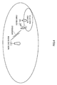
- a heterogeneous network as shown in FIG.4 has been studied, the network composed of a macro cell (e.g., macro base station in FIG.4 ), a femto cell and pico cell (e.g., femto/pico base station in FIG.4 ), or the like.
- the interference in a PDCCH region in any cell may be increased due to influence from the other cells.
- terminals connected with a macro base station are located in the vicinity of a femto cell, especially when the terminals are not allowed to connect with a femto base station, the terminals are greatly interfered with by a femto cell.
- terminals connected to a pico cell are located in the vicinity of a cell edge of the pico cell (e.g., range expansion region), the terminals are greatly interfered with by a macro cell. Consequently, in the PDCCH region, the reception performance of control information (i.e., DCI) in each terminal is deteriorated.
- control information i.e., DCI
- a macro base station performs a transmission process using specific RBs with low transmission power and a femto/pico base station transmits control information to terminals under the femto/pico base station in the R-PDCCH region using the specific RBs, such that the terminals connected with the femto/pico base station (i.e., terminals under femto/pico base station) can receive the control information at a sufficiently low error rate.
- the terminals under the femto/pico base station can receive the control information at a low error rate in the R-PDCCH region using RBs that is less interfered with by the macro base station.
- the macro base station transmits control information in an R-PDCCH region using RBs that are less interfered with by the femto/pico base station (i.e., RBs in which the femto/pico base station processes transmission with low transmission power) and therefore terminals under the macro base station can receive the control information at a low error rate.
- R-PDCCH is mapped in a data transmitting region (i.e., PDSCH region). Accordingly, the number of RBs used for data transmission (i.e., PDSCH region) decreases and thus data throughput may be reduced, when the number of R-PDCCHs used by each terminal increases as the number of terminals under each base station increases.
- the base station includes: a generation section that generates control information transmitted in a first control channel mapped on a resource region which is the same as a resource region to which data for a terminal is allocated or control information transmitted in a second control channel mapped on a resource region which is different from the resource region; and a transmission section that transmits the generated control information, where the amount of information of the control information in the first control channel is smaller than the amount of information of the control information in the second control channel.
- the method of transmitting control information includes: generating control information transmitted in a first control channel mapped on a resource region which is the same as a resource region to which data for a terminal is allocated or control information transmitted in a second control channel mapped on a resource region which is different from the resource region; and transmitting the generated control information, where the amount of information of the control information in the first control channel is smaller than the amount of information of the control information in the second control channel.
- the claimed invention it is possible to minimize deterioration of data throughput even when DCI addressed to a terminal connected with a base station is transmitted in an R-PDCCH region.
- a communication system includes base station 100 and terminal 200.
- Base station 100 is an LTE-A base station
- terminal 200 is an LTE-A terminal.
- FIG.5 is a main block diagram of base station 100 according to Embodiment 1 of the claimed invention.
- PDCCH generating section 104 generates control information transmitted in R-PDCCH (i.e., the first control channel) mapped on a resource region which is the same as a resource region (i.e., PDSCH region) to which data for terminal 200 is allocated or control information transmitted in PDCCH (i,e., the second control channel) mapped on a resource region which is different from the above described resource region.
- RF transmitting section 112 transmits the generated control information.
- the amount of information on the control information in R-PDCCH i.e., the first control channel
- PDCCH i.e., the second control channel
- FIG.6 is a block diagram showing a configuration of base station 100 according to Embodiment 1 of the claimed invention.
- base station 100 includes setting section 101, control section 102, search space setting section 103, PDCCH generating section 104, coding/modulating sections 105, 107, and 108, allocation section 106, multiplexing section 109, inverse fast fourier transform (IFFT) section 110, cyclic prefix (CP) adding section 111, RF transmitting section 112, antenna 113, RF receiving section 114, CP removing section 115, fast fourier transform (FFT) section 116, extracting section 117, inverse discrete fourier transform (IDFT) section 118, data receiving section 119, and ACK/NACK receiving section 120.
- IFFT inverse fast fourier transform
- CP cyclic prefix
- FFT fast fourier transform
- IDFT inverse discrete fourier transform
- Setting section 101 sets a resource region used for transmitting DCI for terminal 200 (i.e., transmission region of DCI), and also sets each transmission mode of uplink and downlink of terminal 200.
- the resource region and the transmission mode are set for each terminal 200 targeted for setting.
- setting section 101 includes transmission region setting section 131 and transmission mode setting section 132.
- Transmission region setting section 131 sets the resource region used for transmitting DCI for terminal 200.
- Candidates of the resource region to be set include a PDCCH region, an R-PDCCH region in slot 0 and an R-PDCCH region in slot 1.
- the PDCCH region is set for terminal 200 in normal times, and the R-PDCCH region in slot 0 or the R-PDCCH region in slot 1 are set for terminal 200 when a large number of terminals 200 performing communication under base station 100 may cause a shortage of the PDCCH region or when it is determined that the interference in the PDCCH region is large.
- transmission region setting section 131 sets whether to perform blind decoding only on the PDCCH region or on both of the PDCCH region and the R-PDCCH region (or only on the R-PDCCH region), for each terminal 200. Any condition is available for determining whether or not a transmission region of DCI includes the R-PDCCH region in transmission region setting section 131. Transmission region setting section 131 sets an RB region targeted when the blind decoding is performed on the R-PDCCH region.
- Transmission mode setting section 132 sets a transmission mode (e.g., spatial multiplexing MIMO transmission, beam forming transmission, non-contiguous band allocation or the like) of each of uplink and downlink of terminal 200, based on the situation of a propagation path or the like of each terminal 200.
- a transmission mode e.g., spatial multiplexing MIMO transmission, beam forming transmission, non-contiguous band allocation or the like
- Setting section 101 sets an RB region that is allocatable to downlink data for terminal 200 (hereinafter, simply referred to as "allocatable RB region") when PDCCH and R-PDCCH are used for transmitting DCI for each terminal 200.
- setting section 101 sets part of a standard setting value candidate group as an RB region to which data can be allocated (i.e., allocation RB candidate group), the region capable of being notified to terminal 200 in R-PDCCH.
- a setting value candidate group i.e., allocation RB candidate group
- the setting value candidate group capable of being notified using downlink control information (DCI) transmitted in PDCCH mapped on a resource region (i.e., PDCCH region) which is different from a resource region (i.e., PDSCH region) to which downlink data is allocated.
- DCI downlink control information
- Setting section 101 transmits setting information, which is set for each terminal 200, including information indicating the transmission region (a resource region) of DCI, information indicating a transmission mode, and information indicating an allocatable RB region, to control section 102, search space setting section 103, PDCCH generating section 104, and coding/modulating section 107.
- the information included in the setting information is notified to each terminal 200 through coding/modulating section 107 as control information in the higher layer (hereinafter, referred to as "RRC control information" or "RRC signaling").
- Control section 102 generates allocation control information that includes HARQ-related information such as MCS information, resource (RB) allocating information, and new data indicator (NDI) or the like depending on the setting information received from setting section 101.
- HARQ-related information such as MCS information, resource (RB) allocating information, and new data indicator (NDI) or the like depending on the setting information received from setting section 101.
- Uplink resource allocating information that indicates an uplink resource to which uplink data of terminal 200 is allocated (e.g., physical uplink shared channel (PUSCH)) or downlink resource allocating information that indicates a downlink resource to which downlink data addressed to terminal 200 is allocated (e.g., physical downlink shared channel (PDSCH)) are generated as the resource allocating information.
- PUSCH physical uplink shared channel
- PDSCH physical downlink shared channel
- control section 102 selects an RB (i.e., setting value) for terminal 200 from the allocatable RB region (i.e., setting value candidate group) set at setting section 101 and generates downlink resource allocation information.
- the downlink resource allocation information indicates which RB in the allocatable RB region is actually used for allocation.
- control section 102 generates allocation control information depending on a transmission mode of the uplink of terminal 200 (i.e., one of DCIs 0A and 0B) allocation control information depending on a transmission mode of the downlink (i.e., one of DCIs 1, 1B, 1D, 2, and 2A), or allocation control information common to all terminals (i.e., DCI 0/1A) for each terminal 200, based on the setting information received from setting section 101.
- a transmission mode of the uplink of terminal 200 i.e., one of DCIs 0A and 0B
- allocation control information depending on a transmission mode of the downlink i.e., one of DCIs 1, 1B, 1D, 2, and 2A
- allocation control information common to all terminals i.e., DCI 0/1A
- control section 102 in a normal data transmission, control section 102 generates allocation control information depending on the transmission mode of each terminal 200 (i.e., one of DCIs 1, 2, 2A, and 2B) such that data transmission can be performed using the transmission mode set for each terminal 200 in order to improve throughput. Consequently, the data transmission can be performed using the transmission mode set for each terminal 200, and therefore the throughput can be improved.
- control section 102 generates the allocation control information in the format common to all terminals (i.e., DCI 0/1A) and transmits data using a robust default transmission mode. Consequently, further robust data transmission is possible even when propagation environment is rapidly changed.
- control section 102 generates allocation control information common to all terminals (i.e., DCI 0/1A) and transmits the information using the default transmission mode, also in transmitting control information on the higher layer (i.e., RRC signaling) for notifying a change of the transmission mode when the propagation path condition is deteriorated.
- the number of information bits of DCI 0/1A common to all terminals is smaller than the numbers of information bits of DCIs 1, 1B, 1D, 2, 2A, 0A, and 0B that depend on a transmission mode.
- DCI 0/1A can be used for transmission with a lower coding rate than DCIs 1, 1B, 1D, 2, 2A, 0A, and 0B when the same CCE aggregation level is set. Consequently, control section 102 uses DCI 0/1A when the propagation path condition is deteriorated, and as a result, even terminal 200, of which the propagation path condition is poor, can receive the allocation control information (and data) with a low error rate.
- Control section 102 generates allocation control information for a common channel (e.g., DCIs 1C and 1A) for data allocation common to a plurality of terminals, such as broadcast information and paging information, other than the allocation control information for terminal-specific data allocation.
- a common channel e.g., DCIs 1C and 1A
- broadcast information and paging information other than the allocation control information for terminal-specific data allocation.
- control section 102 In the generated allocation control information for terminal-specific data allocation, control section 102 outputs: MCS information and NDI to PDCCH generating section 104; uplink resource allocation information to PDCCH generating section 104 and extracting section 117; and downlink resource allocation information to PDCCH generating section 104 and multiplexing section 109. Control section 102 also outputs the generated allocation control information for a common channel to PDCCH generating section 104.
- Search space setting section 103 sets a common search space (C-SS) and UE specific search space (UE-SS) based on a transmission region of DCI indicated by the setting information received from setting section 101.
- C-SS common search space
- UE-SS UE specific search space
- search space setting section 103 sets previously set CCEs (e.g., sixteen CCEs from the first CCE) as C-SS.
- the CCE is a standard unit.
- search space setting section 103 sets UE-SS for each terminal. For example, search space setting section 103 calculates UE-SS of a certain terminal, from a CCE number calculated from a terminal ID of the terminal and a hash function to perform randomization, and the number of CCEs (L) forming a search space.
- FIG.7 shows example setting of UE-SS for certain terminal 200 and C-SS.
- DCI allocation region candidates i.e., CCEs 0 to 3, 4 to 7, 8 to 11, and 12 to 15
- CCEs 0 to 3 and 4 to 7, 8 to 11, and 12 to 15 are set as C-SS in CCE aggregation level 4 of PDCCH.
- two DCI allocation region candidates i.e., CCEs 0 to 7 and 8 to 15
- CCEs 0 to 7 and 8 to 15 are set as C-SS in CCE aggregation level 8 of PDCCH.
- a total of six DCI allocation region candidates are set as C-SS in FIG.7 .
- DCI allocation region candidates i.e., each of CCEs 16 to 21 are set as UE-SS in CCE aggregation level 1 in FIG.7 .
- Six DCI allocation region candidates i.e., formed by dividing CCEs 6 to 17 in pairs are set as UE-SS in CCE aggregation level 2.
- Two DCI allocation region candidates i.e., CCEs 20 to 23 and 24 to 27 are set as UE-SS in CCE aggregation level 4.
- Two DCI allocation region candidates i.e., CCEs 16 to 23 and 24 to 31 are set as UE-SS in CCE aggregation level 8.
- a total of sixteen DCI allocation region candidates are set as UE-SS in FIG.7 .
- search space setting section 103 sets the search spaces that include a plurality of DCI allocation region candidates described above (i.e., C-SS and UE-SS) in the PDCCH region and the R-PDCCH region.
- Search space setting section 103 outputs the search space information that indicates the set C-SS and the set UE-SS of each terminal, to allocation section 106 and coding/modulating section 107.
- PDCCH generating section 104 generates DCI that includes allocation control information for terminal-specific data allocation (i.e., uplink resource allocation information, downlink resource allocation information, MCS information, NDI, or the like for each terminal), or DCI that includes allocation control information for a common channel (i.e., broadcast information common to terminals and paging information or the like), both pieces of allocation control information being received from control section 102.
- PDCCH generating section 104 adds CRC bits to the uplink allocation control information and downlink allocation control information generated for each terminal, and furthermore masks (or, scrambles) the CRC bits by a terminal ID.
- PDCCH generating section 104 generates DCI, which includes a resource region actually used for downlink data (i.e., RBs selected for each terminal 200), from among an allocatable RB region indicated by the setting information received from setting section 101 (i.e., RB candidates available for downlink data). PDCCH generating section 104 then outputs the masked signals to coding/modulating section 105.
- Coding/modulating section 105 performs channel coding and modulation on the DCI received from PDCCH generating section 104, and outputs the modulated signals to allocation section 106.
- coding/modulating section 105 sets a coding rate such that each terminal can achieve sufficient received quality, based on channel quality indicator (CQI) information reported from each terminal. For example, coding/modulating section 105 sets a lower coding rate for a terminal located in the vicinity of a cell boundary (i.e., terminal having lower channel quality).
- CQI channel quality indicator
- Allocation section 106 allocates DCI that includes allocation control information for a common channel and DCI that includes allocation control information for terminal-specific data allocation for each terminal, to CCE or R-CCE in C-SS or CCE or R-CCE in UE-SS for each terminal, respectively, the CCE or R-CCE indicated by the search space information received from search space setting section 103, both pieces of DCI received from coding/modulating section 105.
- allocation section 106 selects a single DCI allocation region candidate from a DCI allocation region candidate group in C-SS (e.g., FIG.7 ).
- Allocation section 106 allocates DCI that includes allocation control information for a common channel to CCE (or R-CCE) (hereinafter, simply referred to as "CCE" without distinguishing between CCE and R-CCE) in the selected DCI allocation region candidate.
- CCE is a resource unit forming PDCCH
- R-CCE is a resource unit forming R-PDCCH.
- allocation target terminal When a DCI format for the terminal targeted for allocation (hereinafter, referred to as "allocation target terminal") depends on a transmission mode (e.g., DCIs 1, 1B, 1D, 2, 2A, 0A, or 0B) allocation section 106 allocates DCI to CCE in UE-SS set for the allocation target terminal. In contrast, when the DCI format for the allocation target terminal is common to all terminals (e.g., DCI 0/1A), allocation section 106 allocates DCI to CCE in UE-SS set for the allocation target terminal or CCE in C-SS.
- a transmission mode e.g., DCIs 1, 1B, 1D, 2, 2A, 0A, or 0B
- allocation section 106 allocates DCI to CCE in UE-SS set for the allocation target terminal or CCE in C-SS.
- the CCE aggregation level allocated to a single piece of DCI differs depending on a coding rate and the number of bits of DCI (i.e., information amount of allocation control information). For example, the coding rate of DCI addressed to a terminal located in the vicinity of a cell boundary is set low, and therefore more physical resources are required. Therefore, allocation section 106 allocates DCI addressed to the terminal located in the vicinity of the cell boundary, to more CCEs.
- Allocation section 106 outputs information on CCE allocated to DCI, to multiplexing section 109 and ACK/NACK receiving section 120. Allocation section 106 also outputs coded and modulated DCI to multiplexing section 109.
- Coding/modulating section 107 performs channel coding and modulation on the setting information received from setting section 101 and the search space information received from search space setting section 103 (i.e., control information on higher layer), and outputs the modulated setting information and search space information to multiplexing section 109.
- Coding/modulating section 108 performs channel coding and modulation on the inputted transmitted data (i.e., downlink data), and outputs the modulated transmitted data signals to multiplexing section 109.
- Multiplexing section 109 multiplexes the coded and modulated DCI signals received from allocation section 106, the setting information and search space information received from coding/modulating section 107 (i.e., control information on higher layer), and the data signals received from coding/modulating section 108 (i.e., PDSCH signals), in the time domain and the frequency domain. Multiplexing section 109 also maps data signals (i.e., PDSCH signals) and PDCCH signals based on the downlink resource allocation information received from control section 102. Multiplexing section 109 may also map the setting information to the PDSCH. Multiplexing section 109 then outputs the multiplexed signals to IFFT section 110.
- IFFT section 110 converts the multiplexed signals of each antenna, which are received from multiplexing section 109, into a time waveform, and CP adding section 111 acquires OFDM signals by adding a CP to this time waveform.
- RF transmitting section 112 performs a transmission radio process (i.e., up-conversion and a digital-to-analog (D/A) conversion, for example) on the OFDM signals inputted from CP adding section 111 and transmits the result through antenna 113.
- a transmission radio process i.e., up-conversion and a digital-to-analog (D/A) conversion, for example
- RF receiving section 114 applies a reception radio process (i.e., down-conversion, analog-to-digital (A/D) conversion or the like) to reception radio signals received in a receiving band through antenna 113, and outputs the resulting received signals to CP removing section 115.
- a reception radio process i.e., down-conversion, analog-to-digital (A/D) conversion or the like
- CP removing section 115 removes the CP from the received signals
- FFT fast fourier transform
- Extracting section 117 extracts uplink data from the frequency domain signals received from FFT section 116 based on the uplink resource allocation information received from control section 102, and IDFT section 118 converts the extracted signals into time domain signals and outputs the time domain signals to data receiving section 119 and ACK/NACK receiving section 120.
- Data receiving section 119 decodes the time domain signals inputted from IDFT section 118. Data receiving section 119 then outputs the decoded uplink data as received data.
- ACK/NACK receiving section 120 extracts ACK/NACK signals from each terminal to downlink data (i.e., PDSCH signals) among the time region signals received from IDFT section 118. Specifically, ACK/NACK receiving section 120 extracts the ACK/NACK signals from uplink control channel (e,g., physical uplink control channel (PUCCH)) based on the information received from allocation section 106.
- uplink control channel e.g., physical uplink control channel (PUCCH)
- the uplink control channel is associated with CCE used for transmitting downlink allocation control information associated with the downlink data.
- ACK/NACK receiving section 120 performs ACK/NACK decision on the extracted ACK/NACK signals.
- CCE is associated with PUCCH in order to eliminate the need for signaling designed for notifying PUCCH from a base station to each terminal, the PUCCH used by each terminal for transmitting the ACK/NACK signals. Accordingly, downlink communication resource can be effectively used. Accordingly to this association, each terminal determines PUCCH used for transmitting ACK/NACK signals, based on the CCE, on which the downlink allocation control information (i.e., DCI) addressed to the terminal is mapped.
- DCI downlink allocation control information
- FIG.8 is a block diagram showing a configuration of terminal 200 according to Embodiment 1 of the claimed invention.
- Terminal 200 is an LTE-A terminal, receives data signals (i.e., downlink data), and transmits ACK/NACK signals corresponding to the data signals to base station 100 using uplink control channel (i.e., PUCCH).
- data signals i.e., downlink data
- ACK/NACK signals corresponding to the data signals to base station 100 using uplink control channel (i.e., PUCCH).
- PUCCH uplink control channel
- terminal 200 includes antenna 201, RF receiving section 202, CP removing section 203, FFT section 204, demultiplexing section 205, setting information receiving section 206, PDCCH receiving section 207, PDSCH receiving section 208, modulating sections 209 and 210, DFT section 211, mapping section 212, IFFT section 213, CP adding section 214, and RF transmitting section 215.
- RF receiving section 202 sets a receiving band based on the band information received from setting information receiving section 206.
- RF receiving section 202 applies a reception radio process (i.e., down-conversion, analog-to-digital (A/D) conversion, or the like) to radio signals received in the receiving band through antenna 201 (i.e., OFDM signals in this embodiment), and outputs the resulting received signals to CP removing section 203.
- the received signals may include PDSCH signals, DCI (allocation control information), and control information in the higher layer including setting information, search space information, and allocatable RB information.
- DCI is allocated to a common search space (C-SS) set to terminal 200 and another terminal, or a UE specific search space (UE-SS) set to terminal 200.
- C-SS common search space
- UE-SS UE specific search space
- CP removing section 203 removes a CP from the received signals, and FFT section 204 converts the received signals from which the CP is removed into frequency domain signals.
- the frequency domain signals are outputted to demultiplexing section 205.
- Demultiplexing section 205 outputs a component, which may include DCI, (i.e., signals extracted from a PDCCH region and an R-PDCCH region) among the signals received from FFT section 204, to PDCCH receiving section 207.
- Demultiplexing section 205 also outputs control signals in the higher layer (e.g., RRC signaling, for example) including the setting information, the search space information and the allocatable RB information, to setting information receiving section 206 and outputs data signals (i.e., PDSCH signals) to PDSCH receiving section 208.
- Demultiplexing section 205 extracts the setting information from signals received at PDSCH receiving section 208 when the control signals in the higher layer including the setting information, the search space information and the allocatable RB information are transmitted through PDSCH.
- Setting information receiving section 206 reads information indicating a terminal ID set to the terminal, band information indicating a resource region set to the terminal, search space information set to the terminal, and information indicating the transmission mode set to the terminal, from the control signals in the higher layer received from demultiplexing section 205.
- the band information set to the terminal is outputted to PDCCH receiving section 207, RF receiving section 202, and RF transmitting section 215.
- the information indicating the terminal ID set to the terminal is outputted to PDCCH receiving section 207 as terminal ID information.
- the search space information set to the terminal is outputted to PDCCH receiving section 207 as search space region information.
- the information indicating a transmission mode set to the terminal is outputted to PDCCH receiving section 207 as transmission mode information.
- the information on allocatable RBs is outputted to PDCCH receiving section 207 as the allocatable RB information.
- PDCCH receiving section 207 acquires DCI addressed to the terminal, through blind decoding (i.e., monitoring) on signals inputted from demultiplexing section 205.
- PDCCH receiving section 207 performs the blind decoding on each of a DCI format for data allocation common to all terminals (e.g., DCI 0/1A), a DCI format depending on a transmission mode set to the terminal (e.g., DCIs 1, 1B, 1D, 2, 2A, 0A and 0B), and a DCI format for a common channel allocation common to all terminals (e.g., DCIs 1C and 1A). Consequently, the DCI that includes allocation control information of each DCI format can be acquired.
- a DCI format for data allocation common to all terminals e.g., DCI 0/1A
- a DCI format depending on a transmission mode set to the terminal e.g., DCIs 1, 1B, 1D, 2, 2A, 0A and 0B
- PDCCH receiving section 207 performs the blind decoding on the DCI formats for a common channel allocation (i.e., DCI 1C and 1A) and the DCI format for data allocation common to all terminals (i.e., DCI 0/1A) in C-SS indicated in the search space region information received from setting information receiving section 206.
- PDCCH receiving section 207 demodulates and decodes each decoding region candidate in C-SS (i.e., candidate in a CCE region allocated to terminal 200) with respect to the size of the DCI format for a common channel allocation and the size of the DCI format for data allocation common to all terminals.
- PDCCH receiving section 207 distinguishes whether the allocation control information of DCI 0/1A is for the common channel or for data allocation addressed to the terminal, by a terminal ID (i.e., ID common to a plurality of terminals, or terminal ID of terminal 200).
- PDCCH receiving section 207 performs the blind decoding (i.e., monitoring) on search spaces set in an R-PDCCH region and acquires the DCI that is addressed to the terminal and is transmitted in R-PDCCH, as with the above described PDCCH region, also when the search space region information received from setting information receiving section 206 includes the R-PDCCH region as a search space region.
- a DCI format targeted when PDCCH receiving section 207 performs blind decoding on the search space set in the R-PDCCH region is set as, for example, a DCI format using RB allocation information in which an allocatable RB region is limited, i.e., a DCI size with a smaller number of bits compared to the PDCCH region.
- terminal 200 may perform blind decoding in transmission regions of a plurality of pieces of DCI in which DCI addressed to terminal 200 may be allocated, without regard to the distribution of search space.
- PDCCH receiving section 207 outputs: downlink resource allocation information included in the DCI addressed to the terminal to PDSCH receiving section 208, when receiving downlink allocation control information; and uplink resource allocation information to mapping section 212 when receiving uplink allocation control information.
- PDSCH receiving section 208 extracts received data (i.e., downlink data) from the PDSCH signals received from demultiplexing section 205, based on the downlink resource allocation information received from PDCCH receiving section 207.
- PDSCH receiving section 208 receives downlink data (i.e., downlink data signals) based on the downlink resource allocation information (i.e., allocation control information) that is addressed to terminal 200 and is allocated to one of a plurality of DCI allocation region candidates (i.e., blind decoding region candidates).
- PDSCH receiving section 208 performs error detection on the extracted received data (i.e., downlink data).
- PDSCH receiving section 208 generates NACK signals as ACK/NACK signals when an error is found in the received data, and generates ACK signals as ACK/NACK signals when no error is found in the received data.
- the ACK/NACK signals are outputted to modulating section 209.
- Modulating section 209 modulates the ACK/NACK signals received from PDSCH receiving section 208 and outputs the modulated ACK/NACK signals to mapping section 212.
- Modulating section 210 modulates transmitted data (i.e., uplink data) and outputs the modulated data signals to DFT section 211.
- DFT section 211 converts the data signals received from modulating section 210 into frequency domain signals and outputs the resulting plurality of frequency components to mapping section 212.
- Mapping section 212 maps, on PUSCH, the plurality of frequency components received from DFT section 211, in accordance with the uplink resource allocation information received from PDCCH receiving section 207. Mapping section 212 specifies PUCCH in accordance with the CCE number received from PDCCH receiving section 207. Mapping section 212 maps the ACK/NACK signals inputted from modulating section 209 on the specified PUCCH described above.
- IFFT section 214 converts a plurality of frequency components mapped on the PUSCH into a time-domain waveform
- CP adding section 214 adds a CP to the time-domain waveform
- RF transmitting section 215 is formed to be able to change a transmission band.
- RF transmitting section 215 sets the transmission band based on the band information received from setting information receiving section 206. Then, RF transmitting section 215 applies a transmission radio process (i.e., up-conversion, digital-to-analog (D/A) conversion, or the like) to signals to which a CP is added, and transmits the result through antenna 201.
- a transmission radio process i.e., up-conversion, digital-to-analog (D/A) conversion, or the like
- setting section 101 sets part of a setting value candidate group of a transmission parameter that can be notified to each terminal 200 using DCI transmitted in PDCCH (hereinafter, referred to as "standard setting value candidate group" since the setting value candidate group functions as the standard of the setting value set associated with R-PDCCH), as a setting value candidate group (i.e., group of settable setting value) of a transmission parameter that can be notified to each terminal 200 using DCI transmitted in R-PDCCH.
- standard setting value candidate group i.e., group of settable setting value
- the above described transmission parameter (i.e., setting value) is set as an RB to which downlink data for terminal 200 is allocated.
- setting section 101 sets some of the plurality of RBs (i.e., all RBs in a system band in this embodiment) forming an allocatable RB region that can be notified to each terminal 200 using DCI transmitted in PDCCH (i.e., setting value candidate group of RB, standard setting value candidate group for R-PDCCH) as an allocatable RB region that can be notified to each terminal 200 using DCI transmitted in R-PDCCH (i.e., setting value candidate group).
- PDCCH i.e., setting value candidate group of RB, standard setting value candidate group for R-PDCCH
- setting section 101 sets the number of allocation RB candidates that can be notified using DCI transmitted in R-PDCCH smaller than the number of allocation RB candidates that can be notified using DCI transmitted in PDCCH.
- the range of allocatable RBs in R-PDCCH is thus narrower than the range of allocatable RBs in PDCCH.
- Control section 102 selects an RB for terminal 200 from the allocatable RB region set at setting section 101 (i.e., setting value candidate group).
- PDCCH generating section 104 generates DCI including the RB (i.e., setting value) actually selected by control section 102 for terminal 200, in the allocatable RB region set at setting section 101. Accordingly, the DCI is transmitted to terminal 200 using a PDCCH region or an R-PDCCH region.
- PDCCH receiving section 207 performs blind decoding (i.e., monitoring) on each search space set in a PDCCH region and an R-PDCCH region, and acquires DCI that is addressed to the terminal 200 and is transmitted in PDCCH or R-PDCCH.
- PDCCH receiving section 207 defines a DCI format having the DCI size, of which the number of bits is smaller than that of a PDCCH region, as the target of blind decoding.
- interference control may be performed between a macro cell and a pico/femto cell in an R-PDCCH region.
- the interference control is also performed on data signals (i.e., PDSCH region, that is, an RB region other than R-PDCCH region).
- controlling an increase and decrease in transmission power (i.e., ON/OFF of transmission) of specific RBs in each cell having a different cell type (i.e., macro cell and pico/femto cell) reduces mutual interference (i.e., inter-cell interference).
- transmission power is increased in a macro cell (i.e., transmission power: large) and decreased in a pico/femto cell (i.e., transmission power: small).
- a macro cell i.e., transmission power: large
- a pico/femto cell i.e., transmission power: small
- the transmission power is decreased in the macro cell (i.e., transmission power: small) and is increased in the pico/femto cell (i.e., transmission power: large).
- decreasing the transmission power in the pico/femto cell decreases the inter-cell interference in the macro cell (i.e., interference from the pico/femto cell) (i.e., interference: low).
- decreasing the transmission power in the macro cell decreases the inter-cell interference in the pico/femto cell (i.e., interference from the macro cell) (i.e., interference: low).
- setting section 101 sets, among a plurality of RBs (i.e., all RBs in a system band) forming an allocatable RB region that can be notified to each terminal 200 using DCI transmitted in PDCCH (i.e., standard setting value candidate group), some RBs that are less interfered with by a base station (i.e., the other cell type) other than base station 100, as an allocatable RB region that can be notified to each terminal 200 using DCI transmitted in R-PDCCH (i.e., setting value candidate group for RBs).
- PDCCH i.e., standard setting value candidate group
- R-PDCCH i.e., setting value candidate group for RBs
- base station 100 is provided in each of a macro cell and a pico/femto cell.
- setting section 101 of base station 100 provided in the macro cell sets an RB region less interfered with by the pico/femto cell (i.e., interference: low), i.e., RB region at the side of lower frequency (7 RBs), as an allocatable RB region that can be notified to terminal 200 using DCI transmitted in R-PDCCH.
- interference: low i.e., RB region at the side of lower frequency (7 RBs
- setting section 101 of base station 100 provided in the pico/femto cell sets an RB region less interfered with by the macro cell (i.e., interference: low), i.e., RB region at the side of higher frequency (7 RBs), as an allocatable RB region that can be notified to terminal 200 using DCI transmitted in R-PDCCH.
- interference: low i.e., RB region at the side of higher frequency (7 RBs
- the macro cell and the pico/femto cell set an RB region in which transmission power of the cells is large (transmission power: large) (i.e., RB region having high interference robustness) as an allocatable RB region that can be notified to terminal 200 using DCI transmitted in R-PDCCH.
- the macro cell and the pico/femto cell set all 14 RBs in a system band, as an allocatable RB region that can be notified to terminal 200 using DCI transmitted in PDCCH.
- each setting section 101 of the macro cell and the pico/femto cell sets the number of RB candidates that can be notified to terminal 200 using DCI transmitted in R-PDCCH (i.e., 7 RBs) smaller than the number of RB candidates that can be notified to terminal 200 using DCI transmitted in PDCCH (i.e., 14 RBs).
- setting section 101 sets some RBs among a plurality of RBs (i.e., RB region in system band) that can be notified using DCI transmitted in PDCCH, as RB candidates that can be notified using DCI transmitted in R-PDCCH.
- setting section 101 limits the target of RB allocation of downlink data only to some of the RB regions (i.e., RB regions in the system band) used when DCI is transmitted in PDCCH.
- the number of bits indicating the result of resource allocation of when DCI is transmitted in R-PDCCH is smaller than that of when DCI is transmitted in PDCCH, and therefore the number of DCI bits (i.e., DCI size) is decreased.
- the DCI size of DCI transmitted in R-PDCCH is smaller than the DCI size of DCI transmitted in PDCCH.
- decreasing the number of bits indicating the result of resource allocation of downlink data for terminal 200 can decrease the total number of RBs used as an R-PDCCH region, the number of bits included in the DCI transmitted in R-PDCCH.
- the deterioration of system throughput can be minimized since decreasing the number of DCI bits can reduce a resource region (i.e., total number of RBs) used, in a PDSCH region, as the R-PDCCH region and limit the reduction of a resource region (i.e., PDSCH region) available for downlink data.
- an allocatable RB region for a terminal to which DCI needs to be transmitted in R-PDCCH is smaller than that for a terminal to which DCI needs to be transmitted in PDCCH, and therefore the flexibility of RB allocation is reduced.
- the terminal to which DCI needs to be transmitted in R-PDCCH i.e., a terminal in which inter-cell interference needs to be reduced by interference control, is likely to be located in the vicinity of the cell boundary. Accordingly, there is a high possibility that an RB with low interference are allocated to the terminal to which DCI needs to be transmitted in R-PDCCH, when resource allocation is performed by, for example, a proportional fair (PF) scheduler or the like.
- PF proportional fair
- RB region that is less interfered with by a pico/femto cell (i.e., RB region at the side of lower frequency (7 RBs)) is allocated for transmitting downlink data to the terminal located in the vicinity of the cell boundary.
- a pico/femto cell i.e., RB region at the side of lower frequency (7 RBs)
- base station 100 sets the number of RB candidates that can be notified to terminal 200 using DCI transmitted in R-PDCCH smaller than the number of RB candidates that can be notified to terminal 200 using DCI transmitted in PDCCH.
- base station 100 sets an RB region, which is less interfered with by a base station of the other cell type, as an allocatable RB region for downlink data addressed to terminal 200 to which DCI is transmitted in R-PDCCH. This can minimize the deterioration of system throughput without reducing the throughput in the terminal to which DCI is transmitted in R-PDCCH.
- setting section 101 sets RBs forming a search space set in R-PDCCH, as an allocatable RB region that can be notified using DCI transmitted in R-PDCCH (i.e., setting value candidate group for RBs).
- R-PDCCH is mapped on a resource region having a range that has a width of 1 RB in a frequency domain.
- a search space for R-PDCCH i.e., DCI allocation region candidates or blind decoding region candidates is therefore set on an RB unit basis.
- setting section 101 sets 7 RBs at the side of lower frequency among 14 RBs in a system band, as a search space for R-PDCCH.
- Setting section 101 sets, among a plurality of RBs (i.e., all RBs in the system band) forming an allocatable RB region that can be notified to terminal 200 using DCI transmitted in PDCCH (i.e., standard setting value candidate group), some RBs that form a search space for R-PDCCH (i.e., 7 RBs at the side of lower frequency), as an allocatable RB region that can be notified to terminal 200 using DCI transmitted in R-PDCCH (i.e., allocatable RB candidates in a setting value candidate group. for RBs).
- some RBs that form the search space set in R-PDCCH are set as allocatable RBs in R-PDCCH.
- setting section 101 sets all 14 RBs in the system band as the allocatable RB region that can be notified to terminal 200 using DCI transmitted in PDCCH.
- setting section 101 sets the number of RB candidates that can be notified to terminal 200 using DCI transmitted in R-PDCCH (i.e., 7 RBs) smaller than the number of RB candidates that can be notified to terminal 200 using DCI transmitted in PDCCH (i.e., 14 RBs).
- decreasing the number of bits indicating the result of resource allocation of downlink data for terminal 200 can reduce, in a PDSCH region, a resource region (i.e., the total number of RBs) used as an R-PDCCH region, the number of bits included in DCI transmitted in R-PDCCH.
- a resource region i.e., the total number of RBs
- the deterioration of system throughput can be minimized since decreasing the number of DCI bits can limit a decrease in the resource region (i.e., PDSCH region) available for downlink data.
- one cell sets low transmission power for specific RBs so as to receive DCI at a sufficiently low error rate, the specific RBs forming an R-PDCCH region set in the other cell.
- interference from another cell is low in RBs forming a search space for R-PDCCH.
- setting section 101 sets an RB region less interfered with by a base station of the other cell type, as an allocatable RB region that can be notified using DCI transmitted in R-PDCCH.
- setting method 1 it is possible to minimize the deterioration of system throughput without reducing the throughput in a terminal to which DCI is transmitted in R-PDCCH, even when DCI for a terminal connected with a base station is transmitted in an R-PDCCH region.
- the same effect as the present setting method can be acquired by defining, instead of a search space for R-PDCCH, an RB region on which a terminal performs blind decoding on R-PDCCH, as an RB candidate that can be notified in R-PDCCH.
- setting section 101 sets part of a standard setting value candidate group for RBs (i.e., allocatable RB region that can be notified to terminal 200 using DCI transmitted in R-PDCCH in this embodiment), as an allocatable RB region (i.e., setting value candidate group for PBs) that can be notified to terminal 200 using DCI transmitted in R-PDCCH mapped on the same resource region as a PDSCH region to which downlink data for terminal 200 is allocated.
- Control section 102 selects RBs for terminal 200 (i.e., setting value) from the above described setting value candidate group set at setting section 101.
- PDCCH generating section 104 generates DCI including RBs (i.e., setting value) selected for terminal 200.
- the range of RBs (i.e., setting value) settable in R-PDCCH differs from the range of RBs settable in PDCCH.
- the range of setting values settable in R-PDCCH is limited more severely than the range of setting values settable in PDCCH.
- the range of setting values settable in R-PDCCH is part of the range of setting values settable in PDCCH.
- control information i.e., DCI
- the number of RBs necessary for receiving DCI at a sufficiently low error rate can be reduced in an R-PDCCH region, and therefore the deterioration of system throughput can be minimized even when DCI for terminal 200 connected with base station 100 is transmitted in the R-PDCCH region.
- setting section 101 sets, among allocatable RB regions that can be notified to terminal 200 using DCI transmitted in PDCCH (i.e., standard setting value candidate group), some RBs that are less interfered with by a base station (i.e., the other cell type) other than base station 100, as an allocatable RB region that can be notified to terminal 200 using DCI transmitted in R-PDCCH.
- PDCCH i.e., standard setting value candidate group
- information on an allocatable RB region that can be notified to a terminal using DCI transmitted in R-PDCCH may be individually notified to each terminal using RRC signaling, or may be notified as broadcast information using broadcast channel (BCH).
- BCH broadcast channel
- new notifying information is unnecessary and the amount of control information can be reduced since a terminal can specify the allocatable RB region that can be notified using information indicating a search space in R-PDCCH.
- band allocation set in terminal 200 may be used as the above described setting value (i.e., transmission parameter).
- the band allocation that can be set to terminal 200 includes contiguous band allocation and non-contiguous band allocation.
- setting section 101 of base station 100 may further limit band allocation (i.e., transmission parameter or setting value) that can be set to terminal 200 to which DCI is transmitted in R-PDCCH, to contiguous band allocation for allocating RBs with continuous numbers (in other words, transmission mode for performing contiguous band allocation transmission).
- the contiguous band allocation for example, information indicating the first RB and a transmission bandwidth of the allocation band is notified.
- allocation control information for notifying the result of resource allocation can be represented with a fewer number of bits than the case of non-contiguous band allocation.
- the contiguous band allocation thus can make the DCI size including the result of resource allocation smaller than the non-contiguous band allocation. Consequently, limiting the band allocation, which can be set to terminal 200 using DCI transmitted in R-PDCCH, to the contiguous band allocation can decrease the number of DCI bits indicating the result of resource allocation and further reduce the resource region used as an R-PDCCH region.
- the deterioration of system throughput can be further minimized since decreasing the size of DCI (i.e., the number of DCI bits) transmitted in R-PDCCH can limit the reduction of a resource region available for downlink data.
- the frequency scheduling effect is made smaller by, for example, limiting an allocatable RB region that can be notified to terminal 200 using DCI transmitted in R-PDCCH as shown in FIGs.9 and 10 . Consequently, the deterioration of throughput is less impacted even when the band allocation that can be set to terminal 200 using DCI transmitted in R-PDCCH is limited to the contiguous band allocation.
- the band allocation that can be set to terminal 200 to which DCI is transmitted in R-PDCCH may be limited to distributed allocation.
- the distributed allocation virtual RBs with continuous numbers, are allocated and the virtual RBs are allocated to respective distributed physical resources (i.e., RBs).
- the distributed allocation can be considered as a method of allocating virtual RBs with continuous numbers. Accordingly, in the distributed allocation, the amount of notifying information is smaller than in the non-contiguous band allocation as described above. This can further minimize the size of DCI transmitted in R-PDCCH (i.e., the number of DCI bits).
- the frequency scheduling effect is also made smaller since an allocatable RB region that can be notified to terminal 200 using DCI transmitted in R-PDCCH is limited as described above. Consequently, the deterioration of throughput is less impacted even when the band allocation that can be set to terminal 200 using DCI transmitted in R-PDCCH is limited to the distributed allocation.
- the same effect can be acquired by limiting a transmission mode that can be set to terminal 200 using DCI transmitted in R-PDCCH to a transmission mode that only supports contiguous band allocation (or contiguous RB number allocation).
- DCI formats 1A, 1B, and 1D for downlink allocation support only the contiguous band allocation (or the contiguous RB number allocation).
- the transmission mode that can be set to terminal 200 using DCI transmitted in R-PDCCH may be limited to a beam forming transmission mode and a multiuser MIMO transmission mode in which these DCI formats are to be monitored.
- each cell i.e., base station
- measures received quality of the other cells hereinafter, referred to as "the other cells quality measurement"
- a base station sets an RB region used for the other cells quality measurement
- a terminal under the base station performs the other cells quality measurement in the set RB region.
- the terminal performs the other cells quality measurement using pilot signals from another cell, the signals received at the set RB region.
- FIG.11 is a block diagram showing a configuration of a terminal according to the present embodiment.
- terminal 300 shown in FIG.11 the same components as with Embodiment 1 (i.e., FIG.8 ) are denoted by the same reference numerals and their overlapping explanations are omitted.
- setting section 101 sets an RB region used for the other cells quality measurement, in addition to the operation of Embodiment 1.
- a terminal connected with each cell performs the other cells quality measurement for handover or the like in an RB region in which another cell does not reduce transmission power, i.e., an RB region in which interference to the cell, with which the terminal currently connected, is high.
- setting section 101 sets an RB region in which another cell (the other cell type) does not decrease (i.e., does not mute) the transmission power, as the RB region used for the other cells quality measurement.
- setting section 101 does not set an RB region in which another cell decreases (i.e., mutes) transmission power, as a target for the other cells quality measurement.
- each cell can precisely measure reception power of signals from another cell and, for example, adequately select a cell that is a handover destination.
- information on an RB region in which another cell (i.e., the other cell type) does not decrease (i.e., does not mute) transmission power is reported from another cell or a control station (not shown) through X2 interface or the like.
- the Setting section 101 notifies, to each terminal 300, the RB region set as the target of the other cells quality measurement as information on RB region for the other cells quality measurement (hereinafter, referred to as "the other cells quality measurement RB region information") using RRC signaling or BCH.
- setting section 101 sets an allocatable RB region for downlink data of when using PDCCH or R-PDCCH for transmitting DCI for each terminal 300, as with Embodiment 1. Specifically, setting section 101 sets, in a system band, an RB region other than an RB region set as the target of the other cells quality measuring (i.e., target for measuring received quality for signals from a base station other than base station 100), as an allocatable RB region that can be notified to terminal 300 using DCI transmitted in R-PDCCH (i.e., setting value candidate group for RBs).
- some RBs other than RBs subject to received quality measurement for signals from a base station other than base station 100 are set as allocatable RBs in R-PDCCH.
- setting information receiving section 301 reads the other cells quality measurement RB region information notified from base station 100, in addition to setting information as with Embodiment 1.
- Setting information receiving section 301 outputs the other cells quality measurement RB region information to other cells measuring section 302, and outputs information indicating an RB region other than the other cells quality measurement RB region indicated by the other cells quality measurement RB region information, to PDCCH receiving section 207 as allocatable RB region information.
- Other cells measuring section 302 performs the other cells quality measurement (i,e., received quality measurement of signals from another cell) with predetermined timing or timing separately indicated by base station 100. Specifically, other cells measuring section 302 reads reference signals (RS) (or pilot signals) of another cell among signals inputted from demultiplexing section 205, the reference signals allocated in an RB region indicated in the other cells quality measurement RB region information received from setting information receiving section 301. Other cells measuring section 302 measures received quality represented by reception power of read RS, path loss, or received signal to interference ratio (SIR) or the like. Other cells measuring section 302 then feeds back the measured results to base station 100.
- RS reference signals
- SIR received signal to interference ratio
- PDCCH receiving section 207 performs blind decoding (i.e., monitor) on each search space set in a PDCCH region and an R-PDCCH region and acquires DCI addressed to the terminal, the DCI transmitted in PDCCH or R-PDCCH.
- a DCI format targeted when PDCCH receiving section 207 performs blind decoding on the search space set in an R-PDCCH region is set as a DCI format using RB allocation information in which an allocatable RB region is limited to an RB region other than the other cells quality measurement RB region, i.e., as a DCI format having a DCI size having a smaller number of bits compared to a PDCCH region.
- an RB region in which another cell decreases (i.e., mutes) transmission power is not subject to the other cells quality measurement.
- reception power (i.e., interference power) of signals from another cell is large in an RB region in which the other cells quality measurement is performed
- the interference power from another cell is small in an RB region not subject to the other cells quality measurement (i.e., RB region in which another cell mutes transmission power).
- Setting section 101 thus sets, among a plurality of RBs (i.e., all RBs in a system band) forming an allocatable RB region (i.e., standard setting value candidate group) that can be notified to each terminal 300 using DCI transmitted in PDCCH, some RBs that form an RB region not subject to the other cells quality measurement (i.e., a resource region other than a resource region subject to received quality measurement for signals from another base station (i.e., the other cell type) other than base station 100), as an allocatable RB region that can be notified to each terminal 300 using DCI transmitted in R-PDCCH (i.e., setting value candidate group for RBs).
- R-PDCCH i.e., setting value candidate group for RBs
- setting section 101 sets an RB region at the side of higher frequency (7 RBs) in a system band (14 RBs), as an RB region subject to the other cells quality measurement.
- setting section 101 sets an RB region (i.e., RB region at the side of lower frequency (7 RBs)) other than an RB region subject to the other cells quality measurement in the system band (14 RBs), as an allocatable RB region that can be notified to terminal 300 using DCI transmitted in R-PDCCH.
- RB region i.e., RB region at the side of lower frequency (7 RBs)
- setting section 101 sets all 14 RBs in the system band as an allocatable RB region that can be notified to terminal 300 using DCI transmitted in PDCCH.
- setting section 101 sets the number of RB candidates that can be notified to terminal 300 using DCI transmitted in R-PDCCH (i.e., 7 RBs) smaller than the number of RB candidates that can be notified to terminal 300 using DCI transmitted in PDCCH (i.e., 14 RBs), as with Embodiment 1.
- base station 100 limits the target of RB allocation of downlink data only to part of RB region among an RB region in the system band, i.e., an RB region other than an RB region subject to the other cells quality measurement.
- decreasing the number of bits indicating the result of resource allocation of downlink data for terminal 300 can reduce a resource region (i.e., the total number of RBs) used as an R-PDCCH region in a PDSCH region, the number of bits included in DCI transmitted in R-PDCCH.
- a resource region i.e., the total number of RBs
- the deterioration of system throughput can be minimized since decreasing the number of DCI bits can limit the reduction of a resource region (i.e., PDSCH region) available for downlink data.
- an allocatable RB region that can be notified to terminal 300 using DCI transmitted in R-PDCCH is an RB region in which another cell mutes transmission power and which is less interfered with by the other cell.
- the reduction of the flexibility of RB allocation has a little impact on throughput in a terminal to which DCI is transmitted in R-PDCCH even when the allocatable RB region that can be notified to terminal 300 using DCI transmitted in R-PDCCH is limited only to an RB region other than an RB region subject to the other cells quality measurement.
- the deterioration of system throughput can be minimized without reducing the throughput in a terminal to which DCI is transmitted in R-PDCCH, even when DCI for a terminal connected with a base station is transmitted in an R-PDCCH region.
- new control information for notifying an allocatable RB region is unnecessary and the amount of control information can be reduced since the allocatable RB region is set from the other cells quality measurement RB region information.
- reducing transmission power in RBs among RB region available for the macro cell can reduce interference power of the pico/femto cell. This can improve the throughput of the pico/femto cell and expand a coverage area of the pico/femto cell.
- a macro cell performs transmission with normal transmission power in an RB region (i.e., 6 RBs in the center part of FIG.13 ) in the center part of a system band (or "component carrier" defined as the standard unit of a communication band), and performs transmission with low transmission power (i.e., muting) in RB regions on both ends, i.e., in the RB regions other than the above center part (i.e., 8 RBs on both ends in total (4 RBs for each end) in FIG.13 ).
- a system band or "component carrier” defined as the standard unit of a communication band
- a pico/femto cell sets an RB region in the center part of the system band (or "component carrier") (i.e., 6 RBs) shown in FIG.13 , as an RB region subject to the other cells quality measurement.
- the pico/femto cell also sets an RB region on both ends other than the above described RB region in the center part (i.e., 8 RBs in total), as an allocatable RB region for downlink data for a terminal to which DCI is transmitted in R-PDCCH.
- SCH/PBCH used for cell detection (i.e., for establishing synchronization with the macro cell) is transmitted in an RB region in the center part of the system band (or "component carrier") (i.e., 6 RBs) shown in FIG.13 .
- a pico/femto cell may define the above RB region in the center part (i.e., 6 RBs) as an RB region subject to the other cells quality measurement, and as a result, a terminal connected with the pico/femto cell may detect a synchronization channel (SCH)/physical broadcast channel (PBCH) of the macro cell and then measure received quality only of the indicated bandwidth, leaving the center frequency as is (i.e., without switching the center frequency).
- the terminal connected with the pico/femto cell is thus not required to perform a frequency switching process.
- a subframe may be provided in a macro cell, the subframe not including an RB region with decreased transmission power and an RB region without transmission (i.e., RB region set as a non-transmission region).
- another cell i.e., pico/femto cell
- a terminal connected with the other cell i.e., pico/femto cell
- the terminal connected with the other cell defines all RBs in the subframe as an RB region subject to the other cells quality measurement and performs the other cells quality measurement using reference signals (RS) received in all RBs. Consequently, in the other cell (i.e., pico/femto cell), the accuracy of the other cells quality measurement for the macro cell (i.e., another cell for the pico/femto cell) can be improved.
- the number of blind decoding attempts for R-PDCCH can be decreased in the subframe, and therefore power consumption of a terminal can be reduced and an error detection rate of DCI can be reduced.
- an RB region subject to the other cells quality measurement may be changed with time. Accordingly, each terminal can measure received quality of the other cells throughout all frequency bands in a system band and can improve the measurement accuracy.
- an allocatable RB region that can be notified to the terminal using DCI transmitted in R-PDCCH is changed depending on the change of the RB region subject to the other cells quality measurement. Consequently, in each cell, RBs for all frequency bands in the system band can be allocated for a terminal to which DCI is transmitted in R-PDCCH and therefore the flexibility of resource allocation can be improved,
- Embodiments 1 and 2 have described a case in which an RB allocated to each terminal is used as a transmission parameter (i.e., setting value) that can be notified to a terminal using DCI.
- a transmission parameter i.e., setting value
- the present embodiment will describe a case in which MCS set for each terminal is used as a transmission parameter (i.e., setting value) that can be notified to a terminal using DCI.
- setting section 101 sets MCS that can be set for each terminal 200 (hereinafter, simply referred to as "settable MCS") when PDCCH or R-PDCCH is used for transmitting DCI to each terminal 200.
- setting section 101 sets part of the standard setting value candidate group, as a settable MCS that can be notified to terminal 200 in R-PDCCH (i.e., setting value candidate group for MCSs).
- the setting value candidate group that can be notified using DCI transmitted in PDCCH i.e., setting value candidate group for MCSs
- the standard setting value candidate group are used as the standard setting value candidate group.
- setting section 101 sets the number of MCS candidates that can be notified using DCI transmitted in R-PDCCH smaller than the number of MCS candidates that can be notified using DCI transmitted in PDCCH.
- the range of MCSs settable in R-PDCCH is thus narrower than the range of settable MCSs in PDCCH.
- setting section 101 sets, among a plurality of MCSs forming settable MCS (i.e., standard setting value candidate group) that can be notified to terminal 200 using DCI transmitted in PDCCH, some MCSs with lower MCS levels (e.g., MCSs with MCS levels not exceeding QPSK), as an MCS candidate group that can be notified to terminal 200 using DCI transmitted in R-PDCCH.
- MCSs with lower MCS levels are set as MCSs settable in R-PDCCH.
- the threshold of settable MCSs may be predetermined, the settable MCSs being able to be notified to terminal 200 using DCI transmitted in R-PDCCH.
- Setting section 101 notifies information on the settable MCS to each terminal 200 as higher layer signals such as RRC signaling or the like.
- Control section 102 selects an MCS for each terminal 200 among the settable MCS (i.e., setting value candidate group for MCSs) set at setting section 101. Control section 102 then generates allocation control information including MCS information indicating the selected MCS level, and PDCCH generating section 104 generates DCI including the allocation control information.
- setting information receiving section 206 reads information on the settable MCS notified from base station 100, in addition to setting information as in Embodiment 1.
- Setting information receiving section 206 outputs the information on the settable MCS to PDCCH receiving section 207 as settable MCS information.
- PDCCH receiving section 207 determines an MCS level notified by DCI (i.e., MCS level set for the terminal), referring to the MCS level of the MCS indicated by the settable MCS information received from setting information receiving section 206, the DCI acquired by performing blind decoding on a search space set in an R-PDCCH region. PDCCH receiving section 207 outputs the determined MCS level to PDSCH receiving section 208.
- setting section 101 uses, for example, an MCS table shown in FIG.14 .
- the MCS table shown in FIG.14 includes eight types of MCSs, i.e., MCS levels 0 to 7. Each MCS level is associated with a modulation scheme (i.e., QPSK, 16QAM, and 64QAM), a coding rate (i.e., 0.2, 0.3, 0.5, and 0.6), and a transport block size (TBS) index (i.e., 0 to 7).
- the TBS index indicates a data size, the correspondence between the TBS index and an actual data size is separately defined as a table depending on the number of allocated RBs.
- a MCS table which includes only the TBS indices depending on the number of allocated RBs among coding rates and TBS indices, may be used since the coding rates are determined depending on the number of allocated RBs and the data size.
- setting section 101 sets MCSs of eight MCS levels 0 to 7 shown in FIG.14 , as settable MCSs (i.e., setting value candidate group for MCSs) that can be notified to terminal 200 using DCI transmitted in PDCCH.
- setting section 101 sets MCSs of four MCS levels 0 to 3 among MCSs of eight MCS levels 0 to 7 shown in FIG.14 , as settable MCSs (i.e., setting value candidate group for MCSs) that can be notified to terminal 200 using DCI transmitted in R-PDCCH.
- setting section 101 sets the number of MCS candidates that can be notified to terminal 200 using DCI transmitted in R-PDCCH (i.e., four levels) smaller than the number of MCS candidates that can be notified to terminal 200 using DCI transmitted in PDCCH (i.e., eight levels).
- Control section 102 sets one of MCSs of MCS levels 0 to 7 for certain terminal 200 to which DCI is transmitted in PDCCH.
- Base station 100 includes, in DCI, the MCS level of the set MCS as MCS information having three bits (i.e., the number of bits that can indicate eight patterns of information), and transmits the DCI to the terminal 200.
- control section 102 sets one of MCSs of MCS levels 0 to 3 for certain terminal 200 to which DCI is transmitted in R-PDCCH.
- Base station 100 includes, in DCI, the MCS level of the set MCS as MCS information having two bits (i.e., the number of bits that can indicate four patterns of information), and transmits the DCI to the terminal 200.
- a single bit is reduced from the number of bits of MCS information (i.e., the number of bits of DCI including MCS information) when DCI is transmitted in R-PDCCH compared with when DCI is transmitted in PDCCH.
- the DCI size of DCI transmitted in R-PDCCH is thus smaller than the DCI size of DCI transmitted in PDCCH.
- decreasing the number of bits indicating MCS information included in DCI transmitted in R-PDCCH can reduce, in a PDSCH region, a resource region (i.e., the total number of RBs) used as an R-PDCCH region.
- a resource region i.e., the total number of RBs
- the deterioration of system throughput can be minimized since decreasing the number of DCI bits can limit the reduction of a resource region (i.e., PDSCH region) available for downlink data.
- base station 100 sets, among settable MCSs (i.e., MCS levels 0 to 7) that can be notified to terminal 200 using DCI transmitted in PDCCH, some MCSs with lower MCS levels (i.e., MCS levels 0 to 4), as settable MCSs (i.e., setting value candidate group for MCSs) that can be notified to terminal 200 using DCI transmitted in R-PDCCH.
- settable MCSs i.e., MCS levels 0 to 7
- some MCSs with lower MCS levels i.e., MCS levels 0 to 4
- settable MCSs i.e., setting value candidate group for MCSs
- a terminal to which DCI needs to be transmitted in R-PDCCH i.e., a terminal in which inter-cell interference needs to be reduced by interference control
- a terminal to which DCI needs to be transmitted in R-PDCCH interference control is performed on data signals as with R-PDCCH and therefore the received quality is improved.
- a high MCS level such as 16QAM, 64QAM or the like, is rarely used (i.e., not frequently used), unlike a terminal located near the cell center.
- limiting settable MCSs which can be notified to terminal 200 using DCI transmitted in R-PDCCH, only to MCSs with lower MCS levels (e.g., MCS levels 0 to 2 (i.e., QPSK) and 3 (i.e., 16QAM)) only prevents the usage of MCS levels that are not frequently used.
- MCS levels 0 to 2 i.e., QPSK
- 3 i.e., 16QAM
- Embodiment 1 it is possible to minimize the deterioration of system throughput without reducing the throughput in a terminal to which DCI is transmitted in R-PDCCH, even when DCI for a terminal connected with a base station is transmitted in an R-PDCCH region.
- a base station may set not only MCSs with continuous MCS levels but also MCSs with discontinuous MCS levels (e.g., MCSs of MCS levels 0, 2, 4, and 6 shown in FIG.14 ) as the MCSs that can be notified to terminal 200 using DCI transmitted in R-PDCCH.
- MCSs MCSs of MCS levels 0, 2, 4, and 6 shown in FIG.14
- the base station may coarsely set an allocation granularity of MCSs that can be notified to terminal 200 using DCI transmitted in R-PDCCH (e.g., use MCSs with MCS levels 0, 2, 4, and 6 every second level).
- a cell-radio network temporary identifier may be used as a terminal ID in the above each embodiment.
- DCI 0/1A has been explained as a format not depending on a transmission mode, the above each embodiment is not limited to this, and any format used without depending on the transmission mode may be possible.
- a DCI format other than DCIs 1, 2, 2A, 0A, and 0B may be used as a format depending on a transmission mode.
- the above embodiments have described a case in which DCI transmitted in R-PDCCH has a smaller amount of information than DCI transmitted in PDCCH.
- the effect of the claimed invention can be acquired even when a DCI format with a small amount of information is transmitted only in R-PDCCH.
- a DCI format with a small amount of information may be transmitted only in R-PDCCH, the DCI format newly defined for an M2M device. Transmitting data with a small number of bits with low transmission power is important in the M2M device, and therefore the above described DCI format with a small amount of information may be set as, for example, the DCI format in which resource allocation is limited.
- the transmission mode of uplink or downlink may include contiguous band allocation transmission.
- DCI formats depending on transmission modes in uplink and downlink are DCI 0 and DCI 1A, respectively.
- the DCI format common to all terminals is the same as the formats depending on the transmission modes, and therefore, in UE-SS, blind decoding may be performed on each type of formats in uplink and downlink.
- the blind decoding is performed only on a single type of format in total.
- Setting DCI 0/1A to DCI depending on a transmission mode and having a wider search space can prevent an increase in a block rate for a terminal for which PDCCH can be allocated in only DCI 0/1A due to originally poor condition of a propagation path.
- the claimed invention is not limited to the above embodiments and can be implemented with various changes.
- the each embodiment can be implemented in appropriate combinations depending on the condition of a terminal.
- CCE and R-CCE explained in the above each embodiment are logical resources.
- the CCE and the R-CCE are arranged in an actually physical time-frequency resource, the CCE is arranged in a distributed manner all over the bands, and the R-CCE is arranged in a distributed manner in specific RBs.
- the same effect as that of the claimed invention can be acquired according to another method of arrangement,
- any control channel transmitted through a frequency resource that may be used for transmitting data can be used to acquire the same effect by applying the claimed invention
- the number of DCI bits is decreased by limiting an allocatable RB region or an allocatable MCS level for DCI transmitted in R-PDCCH.
- part of DCI may be used as a virtual CRC, instead of the decrease in the number of DCI bits.
- a terminal ignores the detected DCI when RB allocation or MCS allocation other than an allocatable RB region or an allocatable MCS level, respectively, is notified. This can reduce an error detection rate of the DCI transmitted in R-PDCCH.
- reference signals and a control channel such as PHICH or PCFICH or the like other than PDCCH may be transmitted.
- the antenna port indicates a logical antenna formed by one or multiple physical antennas, In other words, the antenna port is not limited to represent one physical antenna, and may include an array antenna formed by a plurality of antennas, for example.
- the number of physical antennas for forming the antenna port is not defined, and the antenna port is defined as a minimum unit by which a base station can transmit different reference signals.
- the antenna port may also be defined as a minimum unit for multiplying weighting of a precoding vector.
- each function block employed in the explanation of the above each embodiment may typically be implemented as an LSI constituted by an integrated circuit. These function blocks may be individual chips or partially or totally contained on a single chip.
- LSI is adopted herein but this may also be referred to as "IC,” “system LSI,” “super LSI,” or “ultra LSI,” depending on the differing extents of integration.
- the method of implementing integrated circuit is not limited to LSI, and implementation by means of dedicated circuitry or a general-purpose processor may also be possible.
- LSI manufacture utilization of a field programmable gate array (FPGA) or a reconfigurable processor where connections and settings of circuit cells in an LSI can be reconfigured is also possible.
- FPGA field programmable gate array
- the claimed invention is available for a mobile communication system or the like.
- Reference Signs List 100 Base station 101 Setting section 102 Control section 103 Search space setting section 104 PDCCH generating section 105, 107, 108 Coding/modulating section 106 Allocation section 109 Multiplexing section 110, 213 IFFT section 111, 214 CP adding section 112, 215 RF transmitting section 113, 201 Antenna 114, 202 RF receiving section 115, 203 CP removing section 116, 204 FFT section 117 Extracting section 118 IDFT section 119 Data receiving section 120 ACK/NACK receiving section 131 Transmission region setting section 132 Transmission mode setting section 200, 300 Terminal 205 Demultiplexing section 206, 301 Setting information receiving section 207 PDCCH receiving section 208 PDSCH receiving section 209, 210 Modulating section 211 DFT section 212 Mapping section 302 Other cells measuring section
Applications Claiming Priority (2)
| Application Number | Priority Date | Filing Date | Title |
|---|---|---|---|
| JP2010197772 | 2010-09-03 | ||
| PCT/JP2011/004630 WO2012029245A1 (ja) | 2010-09-03 | 2011-08-19 | 基地局及び制御情報送信方法 |
Publications (1)
| Publication Number | Publication Date |
|---|---|
| EP2613599A1 true EP2613599A1 (de) | 2013-07-10 |
Family
ID=45772372
Family Applications (1)
| Application Number | Title | Priority Date | Filing Date |
|---|---|---|---|
| EP11821270.3A Withdrawn EP2613599A1 (de) | 2010-09-03 | 2011-08-19 | Basisstation und übertragungsverfahren für steuerinformationen |
Country Status (4)
| Country | Link |
|---|---|
| US (1) | US20130155990A1 (de) |
| EP (1) | EP2613599A1 (de) |
| JP (1) | JPWO2012029245A1 (de) |
| WO (1) | WO2012029245A1 (de) |
Cited By (3)
| Publication number | Priority date | Publication date | Assignee | Title |
|---|---|---|---|---|
| EP2816856A4 (de) * | 2012-09-26 | 2015-03-25 | Huawei Device Co Ltd | Verfahren und vorrichtung zur steuerkanalübertragung |
| EP2624626A4 (de) * | 2010-09-30 | 2017-07-26 | Panasonic Intellectual Property Corporation of America | Übertragungsvorrichtung und übertragungsverfahren |
| EP3410796A4 (de) * | 2016-01-29 | 2019-01-16 | China Academy of Telecommunications Technology | Verfahren und vorrichtung zur übertragung und detektion von downlink-steuerinformationen |
Families Citing this family (32)
| Publication number | Priority date | Publication date | Assignee | Title |
|---|---|---|---|---|
| KR102031031B1 (ko) * | 2011-06-20 | 2019-10-15 | 삼성전자 주식회사 | 무선 통신 시스템에서 시분할 복식 프레임 구성 정보 송수신 방법 및 장치 |
| EP2564611B1 (de) | 2011-07-01 | 2015-02-18 | Ofinno Technologies, LLC | Synchronisationssignal- und Steuerungsmeldungen in Mehrträger-OFDM |
| US8369280B2 (en) | 2011-07-01 | 2013-02-05 | Ofinno Techologies, LLC | Control channels in multicarrier OFDM transmission |
| US8582527B2 (en) | 2011-07-01 | 2013-11-12 | Ofinno Technologies, Llc | Hybrid automatic repeat request in multicarrier systems |
| US8842637B2 (en) | 2011-12-04 | 2014-09-23 | Ofinno Technologies, Llc | Carrier information transmission to wireless devices |
| WO2013085307A1 (ko) * | 2011-12-06 | 2013-06-13 | 엘지전자 주식회사 | 무선 통신 시스템에서 원격 송신국의 제어 방법 및 장치 |
| US9497756B2 (en) | 2012-03-25 | 2016-11-15 | Comcast Cable Communications, Llc | Base station radio resource management |
| US9949265B2 (en) | 2012-05-04 | 2018-04-17 | Comcast Cable Communications, Llc | Control channel in a wireless communication system |
| EP3500024A1 (de) | 2012-07-25 | 2019-06-19 | Sun Patent Trust | Basisstationsvorrichtung, endgerätevorrichtung, sendeverfahren und empfangsverfahren |
| KR101846173B1 (ko) * | 2012-09-16 | 2018-04-06 | 엘지전자 주식회사 | 협력적 송신을 지원하는 무선 통신 시스템에서 채널 상태 정보 송수신 방법 및 장치 |
| US9750003B2 (en) * | 2012-12-21 | 2017-08-29 | Samsung Electronics Co., Ltd. | Method and apparatus for transmitting and receiving control channel by beamforming in a wireless communication system |
| WO2014098542A1 (en) * | 2012-12-21 | 2014-06-26 | Samsung Electronics Co., Ltd. | Method and apparatus for transmitting and receiving control channel by beamforming in a wireless communication system |
| CN103944855B (zh) | 2013-01-18 | 2018-08-17 | 中兴通讯股份有限公司 | 调制处理方法及装置 |
| WO2014163302A1 (ko) * | 2013-04-04 | 2014-10-09 | 엘지전자 주식회사 | 소규모 셀에서의 수신 방법 및 사용자 장치 |
| EP2986072B1 (de) * | 2013-04-10 | 2019-09-04 | Sony Corporation | Endgerätevorrichtung und kommunikationsvorrichtung |
| KR102017175B1 (ko) * | 2013-07-12 | 2019-10-21 | 삼성전자주식회사 | 인-밴드 기반 통신 시스템에서 기지국간 통신을 위한 자원 할당 방법 및 장치 |
| CN105594274B (zh) * | 2014-01-29 | 2019-09-03 | 华为技术有限公司 | 数据传输方法和装置 |
| EP3096486B1 (de) | 2014-02-26 | 2018-09-26 | Huawei Technologies Co., Ltd. | Wechsel des steuerungskanals in einem m2m-system durch benutzerendgerät gemäss gemessenem signalpegel, und übertragung von meldungsinformationen an netzwerkseitige vorrichtung |
| US10075309B2 (en) * | 2014-04-25 | 2018-09-11 | Qualcomm Incorporated | Modulation coding scheme (MCS) indication in LTE uplink |
| KR20150136222A (ko) * | 2014-05-26 | 2015-12-07 | 한국전자통신연구원 | 신호 처리 장치 및 방법 |
| US10063672B2 (en) * | 2014-10-02 | 2018-08-28 | Acer Incorporated | Device and method of handling parameter configurations |
| GB2537178A (en) * | 2015-04-10 | 2016-10-12 | Nec Corp | Communication system |
| EP3082287A1 (de) * | 2015-04-16 | 2016-10-19 | Gemalto M2M GmbH | Verfahren zur uplink-kommunikation in einem lte zellulären netzwerk |
| US9538535B2 (en) | 2015-05-11 | 2017-01-03 | Qualcomm Incorporated | Cross-band rate adaption |
| CN110574322B (zh) * | 2017-02-06 | 2023-06-06 | 摩托罗拉移动有限责任公司 | 用于发送和接收同步信号块的方法和装置 |
| US10716105B2 (en) * | 2017-02-14 | 2020-07-14 | Lg Electronics Inc. | Method for transmitting and receiving a physical downlink shared channel and a demodulation reference signal and apparatus therefor |
| CN109391300B (zh) * | 2017-08-11 | 2021-01-26 | 上海朗帛通信技术有限公司 | 一种用于无线通信的用户设备、基站中的方法和装置 |
| US10694480B2 (en) | 2017-08-11 | 2020-06-23 | Lenovo (Singapore) Pte. Ltd. | Determining synchronization signal block positions |
| WO2019095426A1 (zh) * | 2017-11-17 | 2019-05-23 | 华为技术有限公司 | 信息处理方法和无线传输设备 |
| PT3739996T (pt) * | 2018-01-11 | 2024-01-12 | Ntt Docomo Inc | Terminal de utilizador e método de comunicações sem fios |
| US11102676B2 (en) * | 2018-02-20 | 2021-08-24 | Qualcomm Incorporated | Techniques for using downlink control information in new radio |
| CN113661763B (zh) * | 2019-03-29 | 2023-06-23 | Lg电子株式会社 | 用于多传输块调度的信号的发送或接收的方法和装置 |
Family Cites Families (12)
| Publication number | Priority date | Publication date | Assignee | Title |
|---|---|---|---|---|
| WO2007083569A1 (ja) * | 2006-01-18 | 2007-07-26 | Ntt Docomo, Inc. | 基地局、通信端末、送信方法及び受信方法 |
| JP5106796B2 (ja) * | 2006-06-19 | 2012-12-26 | 株式会社エヌ・ティ・ティ・ドコモ | 基地局、送信方法 |
| KR101468490B1 (ko) * | 2007-05-02 | 2014-12-10 | 삼성전자주식회사 | 무선 통신 시스템에서 제어 채널들의 집합을 한정하여 송수신하는 방법 및 장치 |
| US8442069B2 (en) * | 2008-04-14 | 2013-05-14 | Qualcomm Incorporated | System and method to enable uplink control for restricted association networks |
| US8743805B2 (en) * | 2008-10-31 | 2014-06-03 | Panasonic Corporation | Radio terminal device, radio base station device, and channel signal forming method |
| US20100120442A1 (en) * | 2008-11-12 | 2010-05-13 | Motorola, Inc. | Resource sharing in relay operations within wireless communication systems |
| JP5239940B2 (ja) | 2009-02-26 | 2013-07-17 | セイコーエプソン株式会社 | 圧力調整弁および液滴吐出装置 |
| GB2469689A (en) * | 2009-04-24 | 2010-10-27 | Nec Corp | Relay communications system |
| JP2012530407A (ja) * | 2009-06-15 | 2012-11-29 | リサーチ イン モーション リミテッド | キャリアアグリゲーションのための制御チャネルを共有するシステムおよび方法 |
| KR20110020708A (ko) * | 2009-08-24 | 2011-03-03 | 삼성전자주식회사 | Ofdm 시스템에서 셀간 간섭 조정을 위한 제어 채널 구성과 다중화 방법 및 장치 |
| KR20110041386A (ko) * | 2009-10-15 | 2011-04-21 | 엘지전자 주식회사 | 릴레이 방식의 통신 시스템에서 기준신호 전송방법 및 장치 |
| KR101799272B1 (ko) * | 2010-02-03 | 2017-11-20 | 엘지전자 주식회사 | 무선 통신 시스템에서 제어 정보의 전송 방법 및 장치 |
-
2011
- 2011-08-19 JP JP2012531669A patent/JPWO2012029245A1/ja not_active Withdrawn
- 2011-08-19 WO PCT/JP2011/004630 patent/WO2012029245A1/ja active Application Filing
- 2011-08-19 US US13/817,678 patent/US20130155990A1/en not_active Abandoned
- 2011-08-19 EP EP11821270.3A patent/EP2613599A1/de not_active Withdrawn
Non-Patent Citations (1)
| Title |
|---|
| See references of WO2012029245A1 * |
Cited By (6)
| Publication number | Priority date | Publication date | Assignee | Title |
|---|---|---|---|---|
| EP2624626A4 (de) * | 2010-09-30 | 2017-07-26 | Panasonic Intellectual Property Corporation of America | Übertragungsvorrichtung und übertragungsverfahren |
| EP2816856A4 (de) * | 2012-09-26 | 2015-03-25 | Huawei Device Co Ltd | Verfahren und vorrichtung zur steuerkanalübertragung |
| US9215632B2 (en) | 2012-09-26 | 2015-12-15 | Huawei Device Co., Ltd. | Control channel transmission method and equipment |
| US10057820B2 (en) | 2012-09-26 | 2018-08-21 | Huawei Device (Shenzhen) Co., Ltd. | Control channel transmission method and equipment |
| EP3410796A4 (de) * | 2016-01-29 | 2019-01-16 | China Academy of Telecommunications Technology | Verfahren und vorrichtung zur übertragung und detektion von downlink-steuerinformationen |
| US11178686B2 (en) | 2016-01-29 | 2021-11-16 | Datang Mobile Communications Equipment Co., Ltd. | Method and apparatus for transmitting and detecting downlink control information |
Also Published As
| Publication number | Publication date |
|---|---|
| JPWO2012029245A1 (ja) | 2013-10-28 |
| WO2012029245A1 (ja) | 2012-03-08 |
| US20130155990A1 (en) | 2013-06-20 |
Similar Documents
| Publication | Publication Date | Title |
|---|---|---|
| US11490377B2 (en) | Communication apparatus and communication reception method | |
| EP2613599A1 (de) | Basisstation und übertragungsverfahren für steuerinformationen | |
| US11696268B2 (en) | Integrated circuit | |
| JP6410197B2 (ja) | 通信装置、通信方法、及び集積回路 | |
| US9326272B2 (en) | Base station, terminal, transmission method, and reception method | |
| CN108540255B (zh) | 基站装置、终端装置以及集成电路 | |
| WO2011114743A1 (ja) | 基地局及び送信方法 |
Legal Events
| Date | Code | Title | Description |
|---|---|---|---|
| PUAI | Public reference made under article 153(3) epc to a published international application that has entered the european phase |
Free format text: ORIGINAL CODE: 0009012 |
|
| 17P | Request for examination filed |
Effective date: 20130301 |
|
| AK | Designated contracting states |
Kind code of ref document: A1 Designated state(s): AL AT BE BG CH CY CZ DE DK EE ES FI FR GB GR HR HU IE IS IT LI LT LU LV MC MK MT NL NO PL PT RO RS SE SI SK SM TR |
|
| DAX | Request for extension of the european patent (deleted) | ||
| RAP1 | Party data changed (applicant data changed or rights of an application transferred) |
Owner name: PANASONIC INTELLECTUAL PROPERTY CORPORATION OF AME |
|
| RIC1 | Information provided on ipc code assigned before grant |
Ipc: H04W 72/04 20090101AFI20150204BHEP Ipc: H04J 11/00 20060101ALI20150204BHEP Ipc: H04L 5/00 20060101ALI20150204BHEP |
|
| STAA | Information on the status of an ep patent application or granted ep patent |
Free format text: STATUS: THE APPLICATION HAS BEEN WITHDRAWN |
|
| 18W | Application withdrawn |
Effective date: 20150409 |