EP2613456A2 - Method and communication device for handling time offsets between communication device and transmission points - Google Patents
Method and communication device for handling time offsets between communication device and transmission points Download PDFInfo
- Publication number
- EP2613456A2 EP2613456A2 EP13150365.8A EP13150365A EP2613456A2 EP 2613456 A2 EP2613456 A2 EP 2613456A2 EP 13150365 A EP13150365 A EP 13150365A EP 2613456 A2 EP2613456 A2 EP 2613456A2
- Authority
- EP
- European Patent Office
- Prior art keywords
- communication device
- time offsets
- req
- transmission points
- transmission
- Prior art date
- Legal status (The legal status is an assumption and is not a legal conclusion. Google has not performed a legal analysis and makes no representation as to the accuracy of the status listed.)
- Granted
Links
Images



Classifications
-
- H—ELECTRICITY
- H04—ELECTRIC COMMUNICATION TECHNIQUE
- H04W—WIRELESS COMMUNICATION NETWORKS
- H04W8/00—Network data management
-
- H—ELECTRICITY
- H04—ELECTRIC COMMUNICATION TECHNIQUE
- H04W—WIRELESS COMMUNICATION NETWORKS
- H04W56/00—Synchronisation arrangements
- H04W56/004—Synchronisation arrangements compensating for timing error of reception due to propagation delay
- H04W56/0045—Synchronisation arrangements compensating for timing error of reception due to propagation delay compensating for timing error by altering transmission time
-
- H—ELECTRICITY
- H04—ELECTRIC COMMUNICATION TECHNIQUE
- H04B—TRANSMISSION
- H04B7/00—Radio transmission systems, i.e. using radiation field
- H04B7/02—Diversity systems; Multi-antenna system, i.e. transmission or reception using multiple antennas
- H04B7/022—Site diversity; Macro-diversity
- H04B7/024—Co-operative use of antennas of several sites, e.g. in co-ordinated multipoint or co-operative multiple-input multiple-output [MIMO] systems
-
- H—ELECTRICITY
- H04—ELECTRIC COMMUNICATION TECHNIQUE
- H04B—TRANSMISSION
- H04B7/00—Radio transmission systems, i.e. using radiation field
- H04B7/02—Diversity systems; Multi-antenna system, i.e. transmission or reception using multiple antennas
- H04B7/04—Diversity systems; Multi-antenna system, i.e. transmission or reception using multiple antennas using two or more spaced independent antennas
- H04B7/0413—MIMO systems
- H04B7/0417—Feedback systems
-
- H—ELECTRICITY
- H04—ELECTRIC COMMUNICATION TECHNIQUE
- H04B—TRANSMISSION
- H04B7/00—Radio transmission systems, i.e. using radiation field
- H04B7/02—Diversity systems; Multi-antenna system, i.e. transmission or reception using multiple antennas
- H04B7/04—Diversity systems; Multi-antenna system, i.e. transmission or reception using multiple antennas using two or more spaced independent antennas
- H04B7/06—Diversity systems; Multi-antenna system, i.e. transmission or reception using multiple antennas using two or more spaced independent antennas at the transmitting station
- H04B7/0613—Diversity systems; Multi-antenna system, i.e. transmission or reception using multiple antennas using two or more spaced independent antennas at the transmitting station using simultaneous transmission
- H04B7/0615—Diversity systems; Multi-antenna system, i.e. transmission or reception using multiple antennas using two or more spaced independent antennas at the transmitting station using simultaneous transmission of weighted versions of same signal
- H04B7/0619—Diversity systems; Multi-antenna system, i.e. transmission or reception using multiple antennas using two or more spaced independent antennas at the transmitting station using simultaneous transmission of weighted versions of same signal using feedback from receiving side
- H04B7/0636—Feedback format
- H04B7/0639—Using selective indices, e.g. of a codebook, e.g. pre-distortion matrix index [PMI] or for beam selection
-
- H—ELECTRICITY
- H04—ELECTRIC COMMUNICATION TECHNIQUE
- H04L—TRANSMISSION OF DIGITAL INFORMATION, e.g. TELEGRAPHIC COMMUNICATION
- H04L27/00—Modulated-carrier systems
- H04L27/26—Systems using multi-frequency codes
- H04L27/2601—Multicarrier modulation systems
- H04L27/2647—Arrangements specific to the receiver only
- H04L27/2655—Synchronisation arrangements
- H04L27/2662—Symbol synchronisation
-
- H—ELECTRICITY
- H04—ELECTRIC COMMUNICATION TECHNIQUE
- H04L—TRANSMISSION OF DIGITAL INFORMATION, e.g. TELEGRAPHIC COMMUNICATION
- H04L27/00—Modulated-carrier systems
- H04L27/26—Systems using multi-frequency codes
- H04L27/2601—Multicarrier modulation systems
- H04L27/2647—Arrangements specific to the receiver only
- H04L27/2655—Synchronisation arrangements
- H04L27/2668—Details of algorithms
- H04L27/2673—Details of algorithms characterised by synchronisation parameters
- H04L27/2675—Pilot or known symbols
Definitions
- the present invention relates to a method of handling time offsets between a communication device and transmission points and related communication device.
- LTE long-term evolution
- 3GPP 3rd Generation Partnership Project
- UMTS universal mobile telecommunications system
- the LTE system includes a new radio interface and a new radio network architecture that provides a high data rate, low latency, packet optimization, and improved system capacity and coverage.
- a radio access network known as an evolved universal terrestrial radio access network (E-UTRAN) includes multiple evolved Node-Bs (eNBs) for communicating with multiple user equipments (UEs), and communicating with a core network including a mobility management entity (MME), a serving gateway, etc., for Non-Access Stratum (NAS) control.
- E-UTRAN evolved universal terrestrial radio access network
- eNBs evolved Node-Bs
- MME mobility management entity
- serving gateway etc.
- NAS Non-Access Stratum
- LTE-advanced (LTE-A) system is an evolution of the LTE system.
- the LTE-A system targets faster switching between power states, improves performance at the coverage edge of an eNB, and includes advanced techniques, such as carrier aggregation (CA), coordinated multipoint transmission/reception (CoMP), uplink (UL) multiple-input multiple-output (MIMO), etc.
- CA carrier aggregation
- CoMP coordinated multipoint transmission/reception
- UL multiple-input multiple-output
- MIMO multiple-input multiple-output
- the UE and the eNB must support standards developed for the LTE-A system, such as the 3GPP Rel-10 standard or later versions.
- the CoMP is configured to a UE and multiple transmission points, the UE may communicate with the transmission points simultaneously, i.e., access a service via all or part of the transmission points.
- a transmission point can be an eNB, a relay node or a remote antenna of an eNB (e.g., remote radio head (RRH)).
- RRH remote radio head
- an eNB may manage only one transmission point, or may manage multiple transmission points. That is, cell identifications (Cell IDs) of different transmission points may be different (e.g., when being managed by different eNBs), or may be the same (e.g., when being managed by the same eNB).
- Cell IDs cell identifications
- signals transmitted between the UE and the transmission points can be easily recovered due to better quality of the signals.
- the CoMP can be classified into two main categories: Joint Processing (JP) and Coordinated Scheduling/Beamforming (CS/CB).
- JP Joint Processing
- CS/CB Coordinated Scheduling/Beamforming
- a main difference between the JP and the CS/CB is that data of the UE is available at all the transmission points when the JP is configured (i.e. enabled), while the data of the UE is only available at the serving point when the CS/CB is configured.
- the JP can be further classified into two categories: joint transmission (JT) and dynamic point selection.
- the data of the UE can be transmitted from multiple transmission points (e.g., coherently or noncoherently) to the UE to improve signal quality and/or cancel interferences.
- the data of the UE is transmitted from only one of the transmission points (e.g., according to a choice or suggestion of the UE) to the UE to improve the signal quality and/or avoid the interferences.
- the CS/CB is configured, the data of the UE is only transmitted from the serving point to the UE, while other transmission points may adjust scheduling (e.g., stop their transmissions), or adjust beamforming (e.g., move their beams) to mitigate the interferences caused to the UE.
- a time delay between the UE and a transmission point leads to a frequency selectivity and causes mismatch to a preferred matrix index (PMI) (i.e., precoding matrix indicator), so as to degrade throughput of the UE.
- PMI preferred matrix index
- the time delay may be introduced by channel propagation delay (e.g., a number of microseconds) due to scattering and a distance between the UE and the transmission point.
- the time delay may also come from a time offset between the UE and the transmission point.
- the time delay caused by time offset results in considerable frequency selectivity, i.e., a reduced coherence bandwidth. Feeding back the PMI for each 4 resource blocks (RBs) is not sufficient according to the prior art, since channel frequency response (CFR) may vary within a resource block due to the time offset. Thus, compensating the time offset becomes an important topic to be discussed and addressed.
- CFR channel frequency response
- the application aims at providing a method and a communication device for handling time offsets between a communication device and transmission points to solve the abovementioned problems.
- the claimed method of handling a plurality of time offsets between a communication device of a wireless communication system and a plurality of transmission points of the wireless communication system is disclosed.
- the method is utilized in the communication device, and comprises obtaining the plurality of time offsets by using a first reference signal; and transmitting the plurality of time offsets to the plurality of transmission points, respectively; wherein the plurality of transmission points compensate the plurality of time offsets, respectively, when communicating with the communication device.
- Fig. 1 is a schematic diagram of a wireless communication system 10 according to an example of the present invention.
- the wireless communication system 10 is briefly composed of a user equipment (UE) and 7 transmission points TP1-TP7, wherein each of the transmission points TP1-TP7 can perform data transmissions and receptions with the UE.
- the wireless communication system 10 may be a wideband code division multiple access (WCDMA) system such as a universal mobile telecommunications system (UMTS).
- WCDMA wideband code division multiple access
- UMTS universal mobile telecommunications system
- the wireless communication system 10 may be an orthogonal frequency division multiplexing (OFDM) system and/or an orthogonal frequency division multiple access (OFDMA) system, such as a long term evolution (LTE) system, a LTE-Advanced (LTE-A) system or a successor of the LTE-A system.
- OFDM orthogonal frequency division multiplexing
- OFDMA orthogonal frequency division multiple access
- the UE and the transmission points TP1-TP7 are simply utilized for illustrating a structure of the wireless communication system 10.
- the transmission points TP1-TP7 can be referred as NodeBs (NBs) in a universal terrestrial radio access network (UTRAN) of the UMTS.
- the transmission points TP1-TP7 can be evolved NodeBs (eNBs), relay nodes and/or remote radio heads (RRHs) in an evolved UTRAN (E-UTRAN) of the LTE system or the LTE-A system, and are not limited herein.
- the UE can be mobile devices such as mobile phones, laptops, tablet computers, electronic books, and portable computer systems.
- a transmission point and the UE can be seen as a transmitter or a receiver according to transmission direction, e.g., for an uplink (UL), the UE is the transmitter and the transmission point is the receiver, and for a downlink (DL), the transmission point is the transmitter and the UE is the receiver.
- UL uplink
- DL downlink
- the wireless communication system 10 can be seen as a multi-point cooperative network composed of multiple transmission points. That is, the UE may transmit a signal (e.g., a packet) to a first set of the transmission points TP1-TP7, and the UE may receive signals transmitted by a second set of the transmission points TP1-TP7, wherein the first set and the second set may be the same or different. As a result, signal quality of the signals is improved.
- the wireless communication system 10 is referred to the LTE-A system, it means that the wireless communication system 10 supports coordinated multi-point (CoMP) transmission/reception.
- CoMP coordinated multi-point
- the CoMP can be configured as Joint Processing (JP) (e.g., joint transmission (JT) or dynamic point selection) or Coordinated Scheduling/Beamforming (CS/CB), and is not limited.
- JP Joint Processing
- the transmission point TP1 can be seen as a serving point (i.e., serving cell) for the UE, wherein link quality between the transmission point TP1 and the UE is better than link qualities between other transmission points and the UE.
- the serving point can be determined by the UE, the serving point, coordination between transmission points within a cooperating set (e.g., the transmission points TP1-TP3) of the UE and/or coordination between the transmission points TP1-TP7, and is not limited.
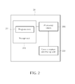
- Fig. 2 is a schematic diagram of a communication device 20 according to an example of the present invention.
- the communication device 20 can be the UE or a transmission point shown in Fig. 1 , but is not limited herein.
- the communication device 20 may include a processing means 200 such as a microprocessor or an Application Specific Integrated Circuit (ASIC), a storage unit 210 and a communication interfacing unit 220.
- the storage unit 210 may be any data storage device that can store a program code 214, accessed by the processing means 200.
- Examples of the storage unit 210 include but are not limited to a subscriber identity module (SIM), read-only memory (ROM), flash memory, random-access memory (RAM), CD-ROM/DVD-ROM, magnetic tape, hard disk, and optical data storage device.
- SIM subscriber identity module
- ROM read-only memory
- RAM random-access memory
- CD-ROM/DVD-ROM magnetic tape
- hard disk hard disk
- optical data storage device optical data storage device.
- the communication interfacing unit 220 is preferably a radio transceiver, and can transmit and receive wireless signals according to processing results of the processing means 200.
- Fig. 3 is a flowchart of a process 30 according to an example of the present invention.
- the process 30 is utilized in the UE shown in Fig. 1 , for handling time offsets T01-T03 between the UE and the transmission points TP1-TP3.
- the process 30 may be compiled into the program code 214 and includes the following steps:
- the UE first obtains (e.g., estimates) the time offsets T01-T03 (e.g., estimated time offsets) by using a reference signal. Then, the UE transmits the time offsets T01-T03 to the transmission points TP1-TP3, respectively. For example, the UE may transmit the time offsets T01-T03 via a control channel (e.g., physical uplink control channel (PUCCH)) to the transmission points TP1-TP3.
- a control channel e.g., physical uplink control channel (PUCCH)
- the reference signal can be any signal known by the UE, e.g., a channel state information reference signal (CSI-RS).
- CSI-RS channel state information reference signal
- the transmission points TP1-TP3 (with corresponding time offsets T01-T03) are simply used for illustrating an example of the present invention. Practically, more (or less) transmission points may communicate with the UE at the same time. Thus, after receiving the time offsets T01-T03, the transmission points TP1-TP3 can compensate the time offsets T01-T03 (e.g., via performing precoding according to the time offsets T01-T03) when communicating with the UE (e.g., when transmitting resource blocks (RBs) to the UE). As a result, throughput of the UE can be improved, and does not degrade due to effect (e.g., phase distortion, precoding matrix mismatch, etc.) of the time offsets T01-T03.
- RBs resource blocks
- a target of the process 30 is that a UE feeds back time offsets corresponding to transmission points which currently communicate with the UE, such that throughput of the UE can be improved. Realization of the process 30 is not limited.
- the UE can generate quantized time offsets by performing a quantization (e.g., linear quantization) on the time offsets T01-T03, respectively. Then, the UE transmits the quantized time offsets to the transmission points TP1-TP3, respectively.
- a range i.e., quantization range
- the UE can simply transmits an indicator indicating a quantized time offset nearest to a time offset without transmitting an actual value of the time offset.
- the UE only needs to transmit 3 bits to a transmission point for indicating a specific quantized time offset. Note that the parameters stated above can be changed according to system requirements and design considerations, and are not limited herein. As a result, overhead caused by transmitting the timing offset can be reduced.
- the UE can also transmit precoding matrix indicators (PMIs) (i.e., preferred matrix indices) to the transmission points TP1-TP3, for the transmission points TP1-TP3 to compensate effects of channel variation and time offset.
- PMIs precoding matrix indicators
- the UE may transmit the PMIs via a control channel (e.g., physical uplink shared channel (PUSCH)) to the transmission points TP1-TP3.
- PUSCH physical uplink shared channel
- the UE first obtains (e.g., estimates) channel information between the UE and the transmission points TP1-TP3 by using a reference signal.
- the reference signal may be the same as that used for obtaining the time offsets.
- the reference signal may be another reference signal (e.g., dedicated for the channel information) for obtaining the channel information.
- the UE determines precoding matrix indicators PMI1-PMI3 corresponding to the transmission points TP1-TP3, respectively, according to the channel information, and transmits the precoding matrix indicators PMI1-PMI3 to the transmission points TP1-TP3, respectively.
- the UE transmits the time offsets T01-T03 periodically with a first period, and the first period is greater than a second period for transmitting the precoding matrix indicators PMI1-PMI3 periodically. That is, the time offsets T01-T03 can be fed back less frequently than the precoding matrix indicators PMI1-PMI3, since the time offsets T01-T03 usually vary slowly (especially true when the UE is in a low-mobility environment).
- the transmission points TP1-TP3 can use both the time offsets T01-T03 and the precoding matrix indicators PMI1-PMI3, to further improve the throughput of the UE.
- overhead for further improving the throughput can be controlled (e.g., reduced or kept) according to system requirements and design considerations, since the time offsets T01-T03 are transmitted less frequently.
- the abovementioned time offsets T01-T03 can be actual values of the time offsets T01-T03.
- the time offsets T01-T03 can be relative values of the time offsets T01-T03 with respect to (e.g., subtracted by) an actual time offset of a reference point (e.g., the transmission point TP1) in a cooperating set (e.g., the transmission points TP1-TP3). That is, the UE may not need to transmit a time offset to the transmission point TP1 (e.g., since the UE have synchronized with the transmission point TP1), and the UE only transmits (TO2-TO1) and (TO3-TO1) to the transmission points TP2 and TP3, respectively.
- the transmission point TP1 does not need to compensate the time offset, but only needs to compensate the channel variation according to the precoding matrix indicator.
- the reference point and/or the cooperating set may be selected from the transmission points TP1-TP7 according to at least one of the time delays, signal amplitudes, channel qualities, reference signal received powers (RSRPs) and reference signal received qualities (RSRQs) of the transmission points TP1-TP7, and is not limited herein.
- the transmission point TP1 is assumed as both the reference point and the serving point in the above example. However, this is not a requirement for realizing the present invention, and the reference point and the serving point can be different transmission points.
- the transmission point after receiving information (e.g., time offset and/or precoding matrix indicator) transmitted by the UE, the transmission point can compensate the time offset and the channel variation according to the information.
- information e.g., time offset and/or precoding matrix indicator
- Fig. 4 is a flowchart of a process 40 according to an example of the present invention.
- the process 40 is utilized in a transmission point (e.g., transmission point TP2) shown in Fig. 1 , for handling the time offset T02 between the UE and the transmission point TP2.
- the process 40 may be compiled into the program code 214 and includes the following steps:
- the transmission point TP2 compensates at least one resource block according to the time offset T02, before transmitting the at least one resource block to the UE. That is, before transmitting the at least one resource block to the UE, the transmission point TP2 compensates the time offset T02 (e.g., via phase rotation or precoding), such that effect (e.g., phase distortion, precoding matrix mismatch, etc.) due to the time offset T02 can be removed or mitigated. As a result, throughput of the UE (as well as throughput of the wireless communication system 10) can be improved, and does not degrade due to effect (e.g., phase distortion, precoding matrix mismatch, etc.) caused by the time offset T02.
- effect e.g., phase distortion, precoding matrix mismatch, etc.
- a target of the process 40 is that a transmission point performing compensation according to a time offset transmitted (i.e., fed back) by the UE, such that effect (e.g., phase distortion, precoding matrix mismatch, etc.) due to the time offset can be removed or mitigated.
- Realization of the process 40 is not limited.
- the transmission point can compensate at least one resource block including only data and a reference signal (e.g., demodulation reference signal (DM-RS)) dedicated to the UE. That is, since time offsets between the transmission point and different UEs may be different (e.g., due to different locations and/or movements of the UEs), detail (e.g., parameters) of compensation for a UE depends on the time offset between the transmission point and the UE. Thus, the transmission point should compensate only the data and the reference signal dedicated to the UE. From another point of view, the transmission point should not perform compensation specific for a UE on at least one resource block comprising common information for multiple UEs.
- DM-RS demodulation reference signal
- the common information may include a synchronization signal, system information (e.g., master information blocks (MIBs), system information blocks (SIBs), paging signal, etc.), a control signal (e.g., uplink grant, downlink assignment, power control signaling, etc.), a cell-specific reference signal (CRS) and/or a positioning reference signal (PRS), but is not limited herein.
- system information e.g., master information blocks (MIBs), system information blocks (SIBs), paging signal, etc.
- MIBs master information blocks
- SIBs system information blocks
- paging signal etc.
- a control signal e.g., uplink grant, downlink assignment, power control signaling, etc.
- CRS cell-specific reference signal
- PRS positioning reference signal
- the UE can also transmit a precoding matrix indicator to a transmission point except a time offset.
- the transmission point can compensate at least one resource block according to the time offset and the precoding matrix indicator before transmitting the at least one resource block to the UE.
- the UE preferably transmits the time offset periodically to the transmission point with a first period, and the first period is greater than a second period for transmitting the precoding matrix indicator to the transmission point periodically.
- the transmission point receives the time offset periodically with the first period, and the precoding matrix indicator periodically with the second period.
- Fig. 5 is a schematic diagram of processing downlink resource blocks according to the present invention.
- Fig. 5 is used for illustrating an example that the transmission point TP2 processes (e.g., precodes) the resource blocks, after receiving the precoding matrix indicator PMI2 and the time offset T02 transmitted by the UE.
- 10 frames FM1-FM10 are considered, wherein each of the frames FM1-FM10 includes 10 subframes SFM1-SFM10.
- one subband including 4 resource blocks RBO-RB3 is considered in the present example, and examples with more subbands including more resource blocks can easily be obtained.
- the transmission point TP2 receives the precoding matrix indicator PMI2 (e.g., represented in 4 bits) transmitted by the UE in each of the subframes SFM1-SFM10 of the frames FM1-FM10. That is, the UE transmits the precoding matrix indicator PMI2 to the transmission point TP2 periodically with the period of one subframe.
- the transmission point TP2 since a time offset usually varies slowly (i.e., a semi-static statistics), the transmission point TP2 only receives the time offset T02 transmitted by the UE in a particular subframe (e.g., the subframe SFM1) of each of the frames FM1-FM10.
- the UE transmits the time offset T02 to the transmission point TP2 periodically with the period of one frame which is greater than the period for transmitting the precoding matrix indicator PMI2.
- the transmission point TP2 can keep using a received (i.e., old) time offset (e.g., for the per-subcarrier compensation or the precoding) for the subband (i.e., the resource blocks RB0-RB3).
- the transmission point TP2 can start to use the new time offset for the subband.
- the transmission point TP2 can keep performing the precoding on the subband (i.e., the resource blocks RBO-RB3) by using a received (i.e., old) precoding matrix indicator.
- the transmission point TP2 can perform the precoding on the subband by using the new precoding matrix indicator.
- the transmission point TP2 can use both the time offset T02 and the precoding matrix indicator PMI2, to further improve the throughput of the UE, while overhead for further improving the throughput can be controlled (e.g., reduced or kept).
- a transmission point can compensate one or more resource blocks by rotating phases of the one or more resource blocks according to a time offset. That is, the transmission point can compensate the time offset via rotating signals (i.e., increasing/decreasing phases of the signals) on subcarriers of the one or more resource blocks in a frequency domain (e.g., per-subcarrier compensation), while the channel variation is compensated via the precoding according to a precoding matrix indicator.
- rotating signals i.e., increasing/decreasing phases of the signals
- subcarriers of the one or more resource blocks in a frequency domain e.g., per-subcarrier compensation
- the transmission point can compensate the time offset and the channel variation jointly by using the precoding according to both the time offset and the precoding matrix indicator as stated above.
- F and G 1 can be updated less frequently because that the UE feeds back the time offset with a lower frequency
- G 2 and V can be updated frequently because the UE feeds back the precoding matrix indicator with a higher frequency.
- the present example simply provides a precoding structure for compensating the time offset and the channel variation via the precoding. Those skilled in the art can readily make modifications or alterations according to the present example.
- the process 60 includes the following steps:
- process 60 Operations and variations of the process 60 can be referred to the above illustration, and are not narrated herein. Note that the process 60 simply illustrates the case including the UE and a single transmission point. However, cases including the UE and multiple transmission points can be readily obtained.
- the abovementioned steps of the processes including suggested steps can be realized by means that could be a hardware, a firmware known as a combination of a hardware device and computer instructions and data that reside as read-only software on the hardware device, or an electronic system.
- hardware can include analog, digital and mixed circuits known as microcircuit, microchip, or silicon chip.
- the electronic system can include a system on chip (SOC), system in package (SiP), a computer on module (COM), and the communication device 20.
- SOC system on chip
- SiP system in package
- COM computer on module
- the present invention provides methods for handling time offsets between communication device and transmission points, to remove or mitigate effects of the time offsets such as phase distortion, precoding matrix mismatch, etc.
- throughput of the UE can be improved, while overhead for further improving the throughput can be controlled (e.g., reduced or kept) according to system requirements and design considerations.
Landscapes
- Engineering & Computer Science (AREA)
- Computer Networks & Wireless Communication (AREA)
- Signal Processing (AREA)
- Databases & Information Systems (AREA)
- Mobile Radio Communication Systems (AREA)
- Time-Division Multiplex Systems (AREA)
Abstract
Description
- The present invention relates to a method of handling time offsets between a communication device and transmission points and related communication device.
- A long-term evolution (LTE) system supporting the 3GPP Rel-8 standard and/or the 3GPP Rel-9 standard are developed by the 3rd Generation Partnership Project (3GPP) as a successor of a universal mobile telecommunications system (UMTS), for further enhancing performance of the UMTS to satisfy increasing needs of users. The LTE system includes a new radio interface and a new radio network architecture that provides a high data rate, low latency, packet optimization, and improved system capacity and coverage. In the LTE system, a radio access network known as an evolved universal terrestrial radio access network (E-UTRAN) includes multiple evolved Node-Bs (eNBs) for communicating with multiple user equipments (UEs), and communicating with a core network including a mobility management entity (MME), a serving gateway, etc., for Non-Access Stratum (NAS) control.
- A LTE-advanced (LTE-A) system, as its name implies, is an evolution of the LTE system. The LTE-A system targets faster switching between power states, improves performance at the coverage edge of an eNB, and includes advanced techniques, such as carrier aggregation (CA), coordinated multipoint transmission/reception (CoMP), uplink (UL) multiple-input multiple-output (MIMO), etc. For a UE and an eNB to communicate with each other in the LTE-A system, the UE and the eNB must support standards developed for the LTE-A system, such as the 3GPP Rel-10 standard or later versions.
- In detail, the CoMP is configured to a UE and multiple transmission points, the UE may communicate with the transmission points simultaneously, i.e., access a service via all or part of the transmission points. For example, a transmission point can be an eNB, a relay node or a remote antenna of an eNB (e.g., remote radio head (RRH)). More specifically, an eNB may manage only one transmission point, or may manage multiple transmission points. That is, cell identifications (Cell IDs) of different transmission points may be different (e.g., when being managed by different eNBs), or may be the same (e.g., when being managed by the same eNB). Thus, signals transmitted between the UE and the transmission points can be easily recovered due to better quality of the signals.
- Besides, when the transmission points are involved in the CoMP, one of the transmission points is a serving point (i.e., serving cell). In general, link quality between the serving point and the UE is better than link qualities between other transmission points and the UE. Further, the CoMP can be classified into two main categories: Joint Processing (JP) and Coordinated Scheduling/Beamforming (CS/CB). A main difference between the JP and the CS/CB is that data of the UE is available at all the transmission points when the JP is configured (i.e. enabled), while the data of the UE is only available at the serving point when the CS/CB is configured. The JP can be further classified into two categories: joint transmission (JT) and dynamic point selection. When the JT is configured, the data of the UE can be transmitted from multiple transmission points (e.g., coherently or noncoherently) to the UE to improve signal quality and/or cancel interferences. When the dynamic point selection is configured, the data of the UE is transmitted from only one of the transmission points (e.g., according to a choice or suggestion of the UE) to the UE to improve the signal quality and/or avoid the interferences. On the other hand, when the CS/CB is configured, the data of the UE is only transmitted from the serving point to the UE, while other transmission points may adjust scheduling (e.g., stop their transmissions), or adjust beamforming (e.g., move their beams) to mitigate the interferences caused to the UE.
- However, a time delay between the UE and a transmission point leads to a frequency selectivity and causes mismatch to a preferred matrix index (PMI) (i.e., precoding matrix indicator), so as to degrade throughput of the UE. In general, the time delay may be introduced by channel propagation delay (e.g., a number of microseconds) due to scattering and a distance between the UE and the transmission point. Alternatively, the time delay may also come from a time offset between the UE and the transmission point. The time delay caused by time offset results in considerable frequency selectivity, i.e., a reduced coherence bandwidth. Feeding back the PMI for each 4 resource blocks (RBs) is not sufficient according to the prior art, since channel frequency response (CFR) may vary within a resource block due to the time offset. Thus, compensating the time offset becomes an important topic to be discussed and addressed.
- This in mind, the application aims at providing a method and a communication device for handling time offsets between a communication device and transmission points to solve the abovementioned problems.
- This is achieved by a method and a communication device handling the time offsets according to
claims 1, 9, 14 and 22. The dependent claims pertain to corresponding further developments and improvements. - As will be seen more clearly from the detailed description following below, the claimed method of handling a plurality of time offsets between a communication device of a wireless communication system and a plurality of transmission points of the wireless communication system is disclosed. The method is utilized in the communication device, and comprises obtaining the plurality of time offsets by using a first reference signal; and transmitting the plurality of time offsets to the plurality of transmission points, respectively; wherein the plurality of transmission points compensate the plurality of time offsets, respectively, when communicating with the communication device.
-
-
Fig. 1 is a schematic diagram of a wireless communication system according to an example of the present invention. -
Fig. 2 is a schematic diagram of a communication device according to an example of the present invention. -
Fig. 3 is a flowchart of a process according to an example of the present invention. -
Fig. 4 is a flowchart of a process according to an example of the present invention. -
Fig. 5 is a schematic diagram of processing downlink resource blocks according to an example of the present invention. -
Fig. 6 is a flowchart of a process according to an example of the present invention. - Please refer to
Fig. 1 , which is a schematic diagram of awireless communication system 10 according to an example of the present invention. Thewireless communication system 10 is briefly composed of a user equipment (UE) and 7 transmission points TP1-TP7, wherein each of the transmission points TP1-TP7 can perform data transmissions and receptions with the UE. Thewireless communication system 10 may be a wideband code division multiple access (WCDMA) system such as a universal mobile telecommunications system (UMTS). Alternatively, thewireless communication system 10 may be an orthogonal frequency division multiplexing (OFDM) system and/or an orthogonal frequency division multiple access (OFDMA) system, such as a long term evolution (LTE) system, a LTE-Advanced (LTE-A) system or a successor of the LTE-A system. - Please note that, the UE and the transmission points TP1-TP7 are simply utilized for illustrating a structure of the
wireless communication system 10. Practically, the transmission points TP1-TP7 can be referred as NodeBs (NBs) in a universal terrestrial radio access network (UTRAN) of the UMTS. Alternatively, the transmission points TP1-TP7 can be evolved NodeBs (eNBs), relay nodes and/or remote radio heads (RRHs) in an evolved UTRAN (E-UTRAN) of the LTE system or the LTE-A system, and are not limited herein. The UE can be mobile devices such as mobile phones, laptops, tablet computers, electronic books, and portable computer systems. Besides, a transmission point and the UE can be seen as a transmitter or a receiver according to transmission direction, e.g., for an uplink (UL), the UE is the transmitter and the transmission point is the receiver, and for a downlink (DL), the transmission point is the transmitter and the UE is the receiver. - Besides, the
wireless communication system 10 can be seen as a multi-point cooperative network composed of multiple transmission points. That is, the UE may transmit a signal (e.g., a packet) to a first set of the transmission points TP1-TP7, and the UE may receive signals transmitted by a second set of the transmission points TP1-TP7, wherein the first set and the second set may be the same or different. As a result, signal quality of the signals is improved. For example, when thewireless communication system 10 is referred to the LTE-A system, it means that thewireless communication system 10 supports coordinated multi-point (CoMP) transmission/reception. The CoMP can be configured as Joint Processing (JP) (e.g., joint transmission (JT) or dynamic point selection) or Coordinated Scheduling/Beamforming (CS/CB), and is not limited. Further, without loss of generality, the transmission point TP1 can be seen as a serving point (i.e., serving cell) for the UE, wherein link quality between the transmission point TP1 and the UE is better than link qualities between other transmission points and the UE. Note that the serving point can be determined by the UE, the serving point, coordination between transmission points within a cooperating set (e.g., the transmission points TP1-TP3) of the UE and/or coordination between the transmission points TP1-TP7, and is not limited. - Please refer to
Fig. 2 , which is a schematic diagram of acommunication device 20 according to an example of the present invention. Thecommunication device 20 can be the UE or a transmission point shown inFig. 1 , but is not limited herein. Thecommunication device 20 may include a processing means 200 such as a microprocessor or an Application Specific Integrated Circuit (ASIC), astorage unit 210 and acommunication interfacing unit 220. Thestorage unit 210 may be any data storage device that can store aprogram code 214, accessed by the processing means 200. Examples of thestorage unit 210 include but are not limited to a subscriber identity module (SIM), read-only memory (ROM), flash memory, random-access memory (RAM), CD-ROM/DVD-ROM, magnetic tape, hard disk, and optical data storage device. Thecommunication interfacing unit 220 is preferably a radio transceiver, and can transmit and receive wireless signals according to processing results of the processing means 200. - Please refer to
Fig. 3 , which is a flowchart of aprocess 30 according to an example of the present invention. Theprocess 30 is utilized in the UE shown inFig. 1 , for handling time offsets T01-T03 between the UE and the transmission points TP1-TP3. Theprocess 30 may be compiled into theprogram code 214 and includes the following steps: - Step 300: Start.
- Step 302: Obtain the time offsets T01-T03 by using a reference signal.
- Step 304: Transmit the time offsets T01-T03 to the transmission points TP1-TP3, respectively.
- Step 306: End.
- According to the
process 30, the UE first obtains (e.g., estimates) the time offsets T01-T03 (e.g., estimated time offsets) by using a reference signal. Then, the UE transmits the time offsets T01-T03 to the transmission points TP1-TP3, respectively. For example, the UE may transmit the time offsets T01-T03 via a control channel (e.g., physical uplink control channel (PUCCH)) to the transmission points TP1-TP3. Note that the reference signal can be any signal known by the UE, e.g., a channel state information reference signal (CSI-RS). Besides, the transmission points TP1-TP3 (with corresponding time offsets T01-T03) are simply used for illustrating an example of the present invention. Practically, more (or less) transmission points may communicate with the UE at the same time. Thus, after receiving the time offsets T01-T03, the transmission points TP1-TP3 can compensate the time offsets T01-T03 (e.g., via performing precoding according to the time offsets T01-T03) when communicating with the UE (e.g., when transmitting resource blocks (RBs) to the UE). As a result, throughput of the UE can be improved, and does not degrade due to effect (e.g., phase distortion, precoding matrix mismatch, etc.) of the time offsets T01-T03. - Please note that, a target of the
process 30 is that a UE feeds back time offsets corresponding to transmission points which currently communicate with the UE, such that throughput of the UE can be improved. Realization of theprocess 30 is not limited. - For example, the UE can generate quantized time offsets by performing a quantization (e.g., linear quantization) on the time offsets T01-T03, respectively. Then, the UE transmits the quantized time offsets to the transmission points TP1-TP3, respectively. Note that a range (i.e., quantization range) of the quantization can be related to a requirement on the time offsets T01-T03, so as to make the quantized time offsets satisfying the requirement. For example, the UE can simply transmits an indicator indicating a quantized time offset nearest to a time offset without transmitting an actual value of the time offset. An example of the linear quantization is stated as follows:

where 2Δ req is the step size of the linear quantization, (0, Lreq ) is the range of the linear quantization, Lini is the initial value of the linear quantization. Considering a 3-bit linear quantization case with 2Δ req = 0.429µs, Lini = 0 and Lreq = 3µs, quantized time offsets (0, 0.43, 0.86, 1.29, 1.71, 2.14, 2.57, 3.0) (i.e., codebook) can be determined. Considering another example for the 3-bit linear quantization with 2Δ req = 0.6µs, Lini = 0 and Lreq = 3µs, quantized time offsets (0, 0.6, 1.2, 1.8, 2.4, 3.0) (i.e., codebook) can be determined. Alternatively, quantized time offsets (0.19, 0.56, 0.94, 1.31, 1.69, 2.05, 2.44, 2.81) (i.e., codebook) can be determined according to another 3-bit linear quantization with 2Δ req = 0.375µs,
Lini = Δ req = 0.1875µs and Lreq = 3µs. Thus, the UE only needs to transmit 3 bits to a transmission point for indicating a specific quantized time offset. Note that the parameters stated above can be changed according to system requirements and design considerations, and are not limited herein. As a result, overhead caused by transmitting the timing offset can be reduced. - Furthermore, the UE can also transmit precoding matrix indicators (PMIs) (i.e., preferred matrix indices) to the transmission points TP1-TP3, for the transmission points TP1-TP3 to compensate effects of channel variation and time offset. For example, the UE may transmit the PMIs via a control channel (e.g., physical uplink shared channel (PUSCH)) to the transmission points TP1-TP3. In detail, the UE first obtains (e.g., estimates) channel information between the UE and the transmission points TP1-TP3 by using a reference signal. Note that the reference signal may be the same as that used for obtaining the time offsets. Alternatively, the reference signal may be another reference signal (e.g., dedicated for the channel information) for obtaining the channel information. Then, the UE determines precoding matrix indicators PMI1-PMI3 corresponding to the transmission points TP1-TP3, respectively, according to the channel information, and transmits the precoding matrix indicators PMI1-PMI3 to the transmission points TP1-TP3, respectively. Preferably, the UE transmits the time offsets T01-T03 periodically with a first period, and the first period is greater than a second period for transmitting the precoding matrix indicators PMI1-PMI3 periodically. That is, the time offsets T01-T03 can be fed back less frequently than the precoding matrix indicators PMI1-PMI3, since the time offsets T01-T03 usually vary slowly (especially true when the UE is in a low-mobility environment). Thus, the transmission points TP1-TP3 can use both the time offsets T01-T03 and the precoding matrix indicators PMI1-PMI3, to further improve the throughput of the UE. At the same time, overhead for further improving the throughput can be controlled (e.g., reduced or kept) according to system requirements and design considerations, since the time offsets T01-T03 are transmitted less frequently.
- Please note that, the abovementioned time offsets T01-T03 can be actual values of the time offsets T01-T03. Alternatively, the time offsets T01-T03 can be relative values of the time offsets T01-T03 with respect to (e.g., subtracted by) an actual time offset of a reference point (e.g., the transmission point TP1) in a cooperating set (e.g., the transmission points TP1-TP3). That is, the UE may not need to transmit a time offset to the transmission point TP1 (e.g., since the UE have synchronized with the transmission point TP1), and the UE only transmits (TO2-TO1) and (TO3-TO1) to the transmission points TP2 and TP3, respectively. In this situation, the transmission point TP1 does not need to compensate the time offset, but only needs to compensate the channel variation according to the precoding matrix indicator. Besides, the reference point and/or the cooperating set may be selected from the transmission points TP1-TP7 according to at least one of the time delays, signal amplitudes, channel qualities, reference signal received powers (RSRPs) and reference signal received qualities (RSRQs) of the transmission points TP1-TP7, and is not limited herein. Note that, the transmission point TP1 is assumed as both the reference point and the serving point in the above example. However, this is not a requirement for realizing the present invention, and the reference point and the serving point can be different transmission points.
- According to the above description, after receiving information (e.g., time offset and/or precoding matrix indicator) transmitted by the UE, the transmission point can compensate the time offset and the channel variation according to the information.
- Please refer to
Fig. 4 , which is a flowchart of aprocess 40 according to an example of the present invention. Theprocess 40 is utilized in a transmission point (e.g., transmission point TP2) shown inFig. 1 , for handling the time offset T02 between the UE and the transmission point TP2. Theprocess 40 may be compiled into theprogram code 214 and includes the following steps: - Step 400: Start.
- Step 402: Receive the time offset T02 transmitted by the UE.
- Step 404: Compensate at least one resource block according to the time offset T02, before transmitting the at least one resource block to the UE.
- Step 406: End.
- According to the
process 40, after receiving the time offset T02 transmitted by the UE, the transmission point TP2 compensates at least one resource block according to the time offset T02, before transmitting the at least one resource block to the UE. That is, before transmitting the at least one resource block to the UE, the transmission point TP2 compensates the time offset T02 (e.g., via phase rotation or precoding), such that effect (e.g., phase distortion, precoding matrix mismatch, etc.) due to the time offset T02 can be removed or mitigated. As a result, throughput of the UE (as well as throughput of the wireless communication system 10) can be improved, and does not degrade due to effect (e.g., phase distortion, precoding matrix mismatch, etc.) caused by the time offset T02. - Please note that, a target of the
process 40 is that a transmission point performing compensation according to a time offset transmitted (i.e., fed back) by the UE, such that effect (e.g., phase distortion, precoding matrix mismatch, etc.) due to the time offset can be removed or mitigated. Realization of theprocess 40 is not limited. - For example, the transmission point can compensate at least one resource block including only data and a reference signal (e.g., demodulation reference signal (DM-RS)) dedicated to the UE. That is, since time offsets between the transmission point and different UEs may be different (e.g., due to different locations and/or movements of the UEs), detail (e.g., parameters) of compensation for a UE depends on the time offset between the transmission point and the UE. Thus, the transmission point should compensate only the data and the reference signal dedicated to the UE. From another point of view, the transmission point should not perform compensation specific for a UE on at least one resource block comprising common information for multiple UEs. Since the compensation specific for the UE may not be proper for other UEs, throughput of other UEs may degrade due to improper compensation. In general, the common information may include a synchronization signal, system information (e.g., master information blocks (MIBs), system information blocks (SIBs), paging signal, etc.), a control signal (e.g., uplink grant, downlink assignment, power control signaling, etc.), a cell-specific reference signal (CRS) and/or a positioning reference signal (PRS), but is not limited herein.
- As mentioned previously, the UE can also transmit a precoding matrix indicator to a transmission point except a time offset. Correspondingly, after receiving the time offset and the precoding matrix indicator, the transmission point can compensate at least one resource block according to the time offset and the precoding matrix indicator before transmitting the at least one resource block to the UE. Besides, the UE preferably transmits the time offset periodically to the transmission point with a first period, and the first period is greater than a second period for transmitting the precoding matrix indicator to the transmission point periodically. Correspondingly, the transmission point receives the time offset periodically with the first period, and the precoding matrix indicator periodically with the second period.
- Please refer to
Fig. 5 , which is a schematic diagram of processing downlink resource blocks according to the present invention.Fig. 5 is used for illustrating an example that the transmission point TP2 processes (e.g., precodes) the resource blocks, after receiving the precoding matrix indicator PMI2 and the time offset T02 transmitted by the UE. As shown inFig. 5 , 10 frames FM1-FM10 are considered, wherein each of the frames FM1-FM10 includes 10 subframes SFM1-SFM10. Further, one subband including 4 resource blocks RBO-RB3 is considered in the present example, and examples with more subbands including more resource blocks can easily be obtained. In detail, the transmission point TP2 receives the precoding matrix indicator PMI2 (e.g., represented in 4 bits) transmitted by the UE in each of the subframes SFM1-SFM10 of the frames FM1-FM10. That is, the UE transmits the precoding matrix indicator PMI2 to the transmission point TP2 periodically with the period of one subframe. On the other hand, since a time offset usually varies slowly (i.e., a semi-static statistics), the transmission point TP2 only receives the time offset T02 transmitted by the UE in a particular subframe (e.g., the subframe SFM1) of each of the frames FM1-FM10. That is, the UE transmits the time offset T02 to the transmission point TP2 periodically with the period of one frame which is greater than the period for transmitting the precoding matrix indicator PMI2. Thus, before receiving a new (i.e., updated) time offset from the UE, the transmission point TP2 can keep using a received (i.e., old) time offset (e.g., for the per-subcarrier compensation or the precoding) for the subband (i.e., the resource blocks RB0-RB3). After receiving the new time offset, the transmission point TP2 can start to use the new time offset for the subband. Similarly, before receiving a new (i.e., updated) precoding matrix indicator from the UE, the transmission point TP2 can keep performing the precoding on the subband (i.e., the resource blocks RBO-RB3) by using a received (i.e., old) precoding matrix indicator. After receiving the new precoding matrix indicator, the transmission point TP2 can perform the precoding on the subband by using the new precoding matrix indicator. As a result, the transmission point TP2 can use both the time offset T02 and the precoding matrix indicator PMI2, to further improve the throughput of the UE, while overhead for further improving the throughput can be controlled (e.g., reduced or kept). - Furthermore, a transmission point can compensate one or more resource blocks by rotating phases of the one or more resource blocks according to a time offset. That is, the transmission point can compensate the time offset via rotating signals (i.e., increasing/decreasing phases of the signals) on subcarriers of the one or more resource blocks in a frequency domain (e.g., per-subcarrier compensation), while the channel variation is compensated via the precoding according to a precoding matrix indicator. For example, before transmitting modulation samples S(k), k=0,...,(N-1) on the subcarriers to the UE, the transmitting point can compensate the modulation samples via the following equation:

where Δn is the time offset, and "mod N" is the modulo-N operation. As can be seen in Eq.2, s(n) can be compensated (i.e., via shifting Δn) by rotating the modulation samples S(k), k=0,...,(N-1) by -2πkΔn/N, k=0,...,(N-1), respectively. - Alternatively, the transmission point can compensate the time offset and the channel variation jointly by using the precoding according to both the time offset and the precoding matrix indicator as stated above. For example, the precoding can be realized via using a precoding structure described as follows:

where F is a phase rotation matrix (i.e., inter-point phase matrix) comprising elements related to the time offset for compensating the time offset, and W0 is a base precoding matrix corresponding to the precoding matrix indicator for compensating the channel variation. Further, W0=V for non-coherent JT and W0=G · V for coherent JT can be obtained, wherein V is a per-point precoding matrix and G is an inter-point precoding matrix. More specifically, G=G1 · G2 can be obtained, wherein G1 is an inter-point amplitude/covariance/polarization matrix and G2 is an inter-point phase matrix for coherent combining. As can be seen from the above, F and G1 can be updated less frequently because that the UE feeds back the time offset with a lower frequency, and G2 and V can be updated frequently because the UE feeds back the precoding matrix indicator with a higher frequency. Note that the present example simply provides a precoding structure for compensating the time offset and the channel variation via the precoding.
Those skilled in the art can readily make modifications or alterations according to the present example. - According to the above description, operations of the wireless communication system 10 (i.e., interactions between a transmission point and the UE) can be summarized into a
process 60 as shown inFig. 6 . Theprocess 60 includes the following steps: - Step 600: Start.
- Step 602: After a reference point is determined within a cooperating set including at least one transmission point, the UE synchronizes with the reference point.
- Step 604: The UE estimates channel estimation between the UE and the transmission point in the cooperating set by using a first reference signal.
- Step 606: The UE determines a precoding matrix indicator corresponding to the transmission point according to the channel estimation.
- Step 608: The UE transmits the precoding matrix indicator to the transmission point periodically with a first period.
- Step 610: The UE obtains a time offset corresponding to the transmission point by using a second reference signal.
- Step 612: The UE transmits the time offset to the transmission point periodically with a second period greater than the first period.
- Step 614: After receiving the time offset and the precoding matrix indicator, the transmission point constructs a precoding matrix according to the time offset and the precoding matrix indicator.
- Step 616: The transmission point performs a precoding on at least one resource block which does not include any common information by using the precoding matrix before transmitting the at least one resource block to the UE, to compensate the time offset and channel variation between the UE and the transmission point.
- Step 618: End.
- Operations and variations of the
process 60 can be referred to the above illustration, and are not narrated herein. Note that theprocess 60 simply illustrates the case including the UE and a single transmission point. However, cases including the UE and multiple transmission points can be readily obtained. - Those skilled in the art should readily make combinations, modifications and/or alterations on the abovementioned description and examples. The abovementioned steps of the processes including suggested steps can be realized by means that could be a hardware, a firmware known as a combination of a hardware device and computer instructions and data that reside as read-only software on the hardware device, or an electronic system. Examples of hardware can include analog, digital and mixed circuits known as microcircuit, microchip, or silicon chip. Examples of the electronic system can include a system on chip (SOC), system in package (SiP), a computer on module (COM), and the
communication device 20. - To sum up, the present invention provides methods for handling time offsets between communication device and transmission points, to remove or mitigate effects of the time offsets such as phase distortion, precoding matrix mismatch, etc. Thus, throughput of the UE can be improved, while overhead for further improving the throughput can be controlled (e.g., reduced or kept) according to system requirements and design considerations.
Claims (26)
- A method of handling a plurality of time offsets between a communication device of a wireless communication system and a plurality of transmission points of the wireless communication system, the method being utilized in the communication device, and characterized by the method comprising:obtaining the plurality of time offsets by using a first reference signal; andtransmitting the plurality of time offsets to the plurality of transmission points, respectively;wherein the plurality of transmission points compensate the plurality of time offsets, respectively, when communicating with the communication device.
- The method of claim 1, characterized in that the step of transmitting the plurality of time offsets to the plurality of transmission points, respectively, comprises:determining a plurality of quantized time offsets by performing a quantization on the plurality of time offsets, respectively; andtransmitting the plurality of quantized time offsets to the plurality of transmission points, respectively.
- The method of claim 2, characterized in that a range of the quantization is related to a requirement on the plurality of time offsets.
- The method of claim 2, characterized in that the quantization is a linear quantization represented by the following equation:

where 2Δ req is a step size of the linear quantization, (0,Lreq ) is a range of the
linear quantization, and Lini is an initial value of the linear quantization. - The method of claim 4, characterized in that the linear quantization is a 3-bit linear quantization with 2Δ req = 0.429µs, Lini = 0 and Lreq = 3µs, for determining the plurality of quantized time offsets of (0, 0.43, 0.86, 1.29, 1.71, 2.14, 2.57, 3.0), with 2Δ req = 0.6µs, Lini = 0 and Lreq = 3µs, for determining the plurality of quantized time offsets of (0, 0.6, 1.2, 1.8, 2.4, 3.0), or with 2Δ req = 0.375µs, Lini = Δ req = 0.1875µs and Lreq = 3µs, for determining the plurality of quantized time offsets of (0.19, 0.56, 0.94, 1.31, 1.69, 2.05, 2.44, 2.81).
- The method of claim 1, further comprising:obtaining channel information between the communication device and the plurality of transmission points by using a second reference signal;determining a plurality of precoding matrix indicators corresponding to the plurality of transmission points, respectively, according to the channel information; andtransmitting the plurality of precoding matrix indicators to the plurality of transmission points, respectively.
- The method of claim 6, characterized in that the communication device transmits the plurality of time offsets periodically with a first period, and the first period is greater than a second period for transmitting the plurality of precoding matrix indicators periodically.
- The method of claim 1, characterized in that the plurality of transmission points are in a cooperating set, one of the plurality of transmission points is a reference point, and the plurality of time offsets are relative time offsets of the plurality of transmission points with respect to an actual time offset of the reference point, respectively.
- A method of handling a time offset between a communication device of a wireless communication system and a transmission point of the wireless communication system, the method being utilized in the transmission point, and characterized by the method comprising:receiving the time offset transmitted by the communication device; andcompensating at least one resource block according to the time offset, before transmitting the at least one resource block to the communication device.
- The method of claim 9, characterized in that the at least one resource block comprises data and a reference signal dedicated to the communication device, or the at least one resource block does not comprise common information for a plurality of communication devices in the wireless communication system.
- The method of claim 9, further comprising:receiving a precoding matrix indicator transmitted by the communication device; andcompensating the at least one resource block according to the time offset and the precoding matrix, before transmitting the at least one resource block to the communication device.
- The method of claim 11, characterized in that the transmission point receives the time offset periodically with a first period, and the first period is greater than a second period for receiving the precoding matrix indicator periodically.
- The method of claim 9, characterized in that the transmission point compensates the at least one resource block by rotating phases of the at least one resource block according to the time offset.
- A communication device of a wireless communication system for handling a plurality of time offsets between the communication device and a plurality of transmission points of the wireless communication system, characterized by the communication device comprising:a processing means for executing a program; anda memory coupled to the processing means for storing the program; wherein the program instructs the processing means to perform the following steps:obtaining the plurality of time offsets by using a first reference signal; andtransmitting the plurality of time offsets to the plurality of transmission points, respectively;wherein the plurality of transmission points compensate the plurality of time offsets, respectively, when communicating with the communication device.
- The communication device of claim 14, characterized in that the step of transmitting the plurality of time offsets to the plurality of transmission points, respectively, comprises:determining a plurality of quantized time offsets by performing a quantization on the plurality of time offsets, respectively; andtransmitting the plurality of quantized time offsets to the plurality of transmission points, respectively.
- The communication device of claim 15, characterized in that a range of the quantization is related to a requirement on the plurality of time offsets.
- The communication device of claim 15, characterized in that the quantization is a linear quantization represented by the following equation:

where 2Δ req is a step size of the linear quantization, (0,Lreq ) is a range of the linear quantization, and Lini is an initial value of the linear quantization. - The communication device of claim 17, characterized in that the linear quantization is a 3-bit linear quantization with 2Δ req = 0.429µs, Lini = 0 and Lreq = 3µs, for determining the plurality of quantized time offsets of (0, 0.43, 0.86, 1.29, 1.71, 2.14, 2.57, 3.0), with 2Δ req = 0.6µs, Lini = 0 and Lreq = 3µs, for determining the plurality of quantized time offsets of (0, 0.6, 1.2, 1.8, 2.4, 3.0), or with 2Δ req = 0.375µs, Lini = Δ req = 0.1875µs and Lreq = 3µs, for determining the plurality of quantized time offsets of (0.19, 0.56, 0.94, 1.31, 1.69, 2.05, 2.44, 2.81).
- The communication device of claim 14, characterized in that the program further instructs the processing means to perform the following steps:obtaining channel information between the communication device and the plurality of transmission points by using a second reference signal;determining a plurality of precoding matrix indicators corresponding to the plurality of transmission points, respectively, according to the channel information; andtransmitting the plurality of precoding matrix indicators to the plurality of transmission points, respectively.
- The communication device of claim 19, characterized in that the communication device transmits the plurality of time offsets periodically with a first period, and the first period is greater than a second period for transmitting the plurality of precoding matrix indicators periodically.
- The communication device of claim 14, characterized in that the plurality of transmission points are in a cooperating set, one of the plurality of transmission points is a reference point, and the plurality of time offsets are relative time offsets of the plurality of transmission points with respect to an actual time offset of the reference point, respectively.
- A transmission point of a wireless communication system for handling a time offset between a communication device of the wireless communication system and the transmission point, characterized by the transmission point comprising:a processing means for executing a program; anda memory coupled to the processing means for storing the program; wherein the program instructs the processing means to perform the following steps:receiving the time offset transmitted by the communication device; andcompensating at least one resource block according to the time offset, before transmitting the at least one resource block to the communication device.
- The transmission point of claim 22, characterized in that the at least one resource block comprises data and a reference signal dedicated to the communication device, or the at least one resource block does not comprise common information for a plurality of communication devices in the wireless communication system.
- The transmission point of claim 22, characterized in that the program further instructs the processing means to perform the following steps:receiving a precoding matrix indicator transmitted by the communication device; andcompensating the at least one resource block according to the time offset and the precoding matrix, before transmitting the at least one resource block to the communication device.
- The transmission point of claim 24, characterized in that the transmission point receives the time offset periodically with a first period, and the first period is greater than a second period for receiving the precoding matrix indicator periodically.
- The transmission point of claim 22, characterized in that the transmission point compensates the at least one resource block by rotating phases of the at least one resource block according to the time offset.
Applications Claiming Priority (2)
| Application Number | Priority Date | Filing Date | Title |
|---|---|---|---|
| US201261583575P | 2012-01-05 | 2012-01-05 | |
| US13/733,891 US9008712B2 (en) | 2012-01-05 | 2013-01-04 | Method and communication device for handling time offsets between communication device and transmission points |
Publications (3)
| Publication Number | Publication Date |
|---|---|
| EP2613456A2 true EP2613456A2 (en) | 2013-07-10 |
| EP2613456A3 EP2613456A3 (en) | 2013-08-21 |
| EP2613456B1 EP2613456B1 (en) | 2019-02-27 |
Family
ID=47632811
Family Applications (1)
| Application Number | Title | Priority Date | Filing Date |
|---|---|---|---|
| EP13150365.8A Active EP2613456B1 (en) | 2012-01-05 | 2013-01-07 | Method and communication device for handling time offsets between communication device and transmission points |
Country Status (4)
| Country | Link |
|---|---|
| US (1) | US9008712B2 (en) |
| EP (1) | EP2613456B1 (en) |
| CN (1) | CN103354659B (en) |
| TW (1) | TWI466581B (en) |
Cited By (1)
| Publication number | Priority date | Publication date | Assignee | Title |
|---|---|---|---|---|
| CN115378780A (en) * | 2021-12-29 | 2022-11-22 | 比科奇微电子(杭州)有限公司 | Carrier aggregation method and device for carrier modulation signal and electronic equipment |
Families Citing this family (10)
| Publication number | Priority date | Publication date | Assignee | Title |
|---|---|---|---|---|
| JP5865505B2 (en) | 2011-11-04 | 2016-02-17 | インテル・コーポレーション | Timing synchronization for downlink (DL) transmission in cooperative multipoint (CoMP) systems |
| US20130242952A1 (en) * | 2012-03-15 | 2013-09-19 | Htc Corporation | Methods for solving timing offset in the arrival times of reference signal and communications apparatus utilizing the same |
| US9728008B2 (en) | 2012-12-10 | 2017-08-08 | Nant Holdings Ip, Llc | Interaction analysis systems and methods |
| US20150109997A1 (en) * | 2013-10-21 | 2015-04-23 | Alexander Sirotkin | Apparatus, system and method of interfacing between a cellular manager and a wlan access device |
| TWI616109B (en) | 2014-11-05 | 2018-02-21 | 財團法人資訊工業策進會 | Direct communication network system and signal synchronization method thereof |
| US9832747B2 (en) | 2015-09-21 | 2017-11-28 | Intel IP Corporation | Mobile terminal device, mobile processing circuit and method of processing signals |
| US10158464B2 (en) * | 2015-09-25 | 2018-12-18 | Intel IP Corporation | Mobile terminal devices, mobile processing circuits, and methods of processing signals |
| CN114375611B (en) * | 2020-07-31 | 2024-03-19 | 北京小米移动软件有限公司 | Multi-connection communication method, device and computer-readable storage medium |
| US20250080298A1 (en) * | 2023-08-30 | 2025-03-06 | Qualcomm Incorporated | User equipment (ue)-assisted time and phase synchronization for coherent joint transmission |
| WO2026016030A1 (en) * | 2024-07-16 | 2026-01-22 | Qualcomm Incorporated | Techniques for assisted time and phase synchronization based on non-precoded channel state information reference signal |
Family Cites Families (7)
| Publication number | Priority date | Publication date | Assignee | Title |
|---|---|---|---|---|
| KR101618283B1 (en) | 2009-05-22 | 2016-05-04 | 삼성전자주식회사 | Method of information feedback for coordinated multiple point communications |
| PL2908585T3 (en) | 2009-06-19 | 2017-12-29 | Interdigital Patent Holdings, Inc. | Signaling uplink control information in lte-a |
| US8948028B2 (en) * | 2009-10-13 | 2015-02-03 | Qualcomm Incorporated | Reporting of timing information to support downlink data transmission |
| WO2011079406A1 (en) | 2009-12-28 | 2011-07-07 | Telefonaktiebolaget L M Ericsson (Publ) | Method and arrangement of delay calibration for ofdm system |
| CN102118825B (en) | 2009-12-31 | 2013-12-04 | 华为技术有限公司 | Method for realizing multipoint joint transmission, terminal and system |
| US8638867B2 (en) * | 2011-04-27 | 2014-01-28 | Broadcom Corporation | Methods and apparatus for compensating for propagation delays in coordinated multi-point transmission |
| US9209950B2 (en) * | 2011-10-03 | 2015-12-08 | Qualcomm Incorporated | Antenna time offset in multiple-input-multiple-output and coordinated multipoint transmissions |
-
2013
- 2013-01-04 US US13/733,891 patent/US9008712B2/en active Active
- 2013-01-04 TW TW102100327A patent/TWI466581B/en active
- 2013-01-05 CN CN201310001984.0A patent/CN103354659B/en active Active
- 2013-01-07 EP EP13150365.8A patent/EP2613456B1/en active Active
Non-Patent Citations (1)
| Title |
|---|
| None |
Cited By (2)
| Publication number | Priority date | Publication date | Assignee | Title |
|---|---|---|---|---|
| CN115378780A (en) * | 2021-12-29 | 2022-11-22 | 比科奇微电子(杭州)有限公司 | Carrier aggregation method and device for carrier modulation signal and electronic equipment |
| CN115378780B (en) * | 2021-12-29 | 2023-07-18 | 比科奇微电子(杭州)有限公司 | Carrier aggregation method and device for carrier modulation signal, electronic equipment |
Also Published As
| Publication number | Publication date |
|---|---|
| US20130178202A1 (en) | 2013-07-11 |
| US9008712B2 (en) | 2015-04-14 |
| TW201330682A (en) | 2013-07-16 |
| EP2613456A3 (en) | 2013-08-21 |
| TWI466581B (en) | 2014-12-21 |
| CN103354659B (en) | 2016-05-04 |
| EP2613456B1 (en) | 2019-02-27 |
| CN103354659A (en) | 2013-10-16 |
Similar Documents
| Publication | Publication Date | Title |
|---|---|---|
| EP2613456B1 (en) | Method and communication device for handling time offsets between communication device and transmission points | |
| US12476678B2 (en) | Downlink multiple input multiple output enhancements for single-cell with remote radio heads | |
| US10972168B2 (en) | User equipment and method for wireless communication | |
| EP3327941B1 (en) | Method and apparatus for transmitting and receiving feedback information for inter-cell cooperative transmission in wireless communication cellular system | |
| WO2024031473A1 (en) | Reporting frequency and doppler parameters for coherent joint transmission (cjt) and mobility | |
| US20250202635A1 (en) | Downlink (dl) pre-compensation and quasi-co-location (qcl) signaling for coherent joint transmission (cjt) | |
| US8787261B2 (en) | Base station apparatus, mobile station apparatus and transmission power control method | |
| EP3437224B1 (en) | Low complexity multi-configuration csi reporting | |
| CN111641485B (en) | User device and transmission method | |
| US10892808B2 (en) | Method of acquiring channel state information | |
| US8565688B2 (en) | Method of reducing feedback load and feedback overhead in a multi-cell cooperative network and related communication device | |
| EP2680477B1 (en) | Method and apparatus of handling collisions among channel state information reports | |
| US20130258886A1 (en) | Method and apparatus for channel state information feedback in a coordinated multi-point communication system | |
| EP3024155B1 (en) | Method for transmitting data symbol using antenna correlation in wireless access system which supports massive antenna | |
| CN119316920A (en) | Signal synchronization method and communication device | |
| US10142002B2 (en) | Method of handling multiuser CQI for MU-MIMO and related communication device | |
| WO2020147033A1 (en) | Method, device and computer readable medium for estimating channel state information | |
| EP2742626B1 (en) | Tae/fae compensation for antenna ports in comp transmissio | |
| KR20110093555A (en) | Method and apparatus for transmitting reference signal according to feedback of terminal | |
| JP2017163585A (en) | Radio base station, user terminal, and radio communication method | |
| WO2025177184A1 (en) | Methods for determination and indication of reference downlink reference signal (dl-rs) for inter-transmission-reception point (inter-trp) delay, frequency, and phase difference report | |
| CN120858605A (en) | Used to compensate for timing offset between transmission and reception points | |
| HK1246021A1 (en) | Csi reporting for a set of csi-rs resources |
Legal Events
| Date | Code | Title | Description |
|---|---|---|---|
| PUAI | Public reference made under article 153(3) epc to a published international application that has entered the european phase |
Free format text: ORIGINAL CODE: 0009012 |
|
| AK | Designated contracting states |
Kind code of ref document: A2 Designated state(s): AL AT BE BG CH CY CZ DE DK EE ES FI FR GB GR HR HU IE IS IT LI LT LU LV MC MK MT NL NO PL PT RO RS SE SI SK SM TR |
|
| AX | Request for extension of the european patent |
Extension state: BA ME |
|
| PUAL | Search report despatched |
Free format text: ORIGINAL CODE: 0009013 |
|
| AK | Designated contracting states |
Kind code of ref document: A3 Designated state(s): AL AT BE BG CH CY CZ DE DK EE ES FI FR GB GR HR HU IE IS IT LI LT LU LV MC MK MT NL NO PL PT RO RS SE SI SK SM TR |
|
| AX | Request for extension of the european patent |
Extension state: BA ME |
|
| RIC1 | Information provided on ipc code assigned before grant |
Ipc: H04L 27/26 20060101ALI20130715BHEP Ipc: H04B 7/02 20060101AFI20130715BHEP Ipc: H04W 56/00 20090101ALI20130715BHEP |
|
| 17P | Request for examination filed |
Effective date: 20140221 |
|
| RBV | Designated contracting states (corrected) |
Designated state(s): AL AT BE BG CH CY CZ DE DK EE ES FI FR GB GR HR HU IE IS IT LI LT LU LV MC MK MT NL NO PL PT RO RS SE SI SK SM TR |
|
| GRAP | Despatch of communication of intention to grant a patent |
Free format text: ORIGINAL CODE: EPIDOSNIGR1 |
|
| STAA | Information on the status of an ep patent application or granted ep patent |
Free format text: STATUS: GRANT OF PATENT IS INTENDED |
|
| INTG | Intention to grant announced |
Effective date: 20180723 |
|
| RIN1 | Information on inventor provided before grant (corrected) |
Inventor name: HO, CHUNG-LIEN |
|
| GRAS | Grant fee paid |
Free format text: ORIGINAL CODE: EPIDOSNIGR3 |
|
| RAP1 | Party data changed (applicant data changed or rights of an application transferred) |
Owner name: ACER INCORPORATED |
|
| GRAA | (expected) grant |
Free format text: ORIGINAL CODE: 0009210 |
|
| STAA | Information on the status of an ep patent application or granted ep patent |
Free format text: STATUS: THE PATENT HAS BEEN GRANTED |
|
| AK | Designated contracting states |
Kind code of ref document: B1 Designated state(s): AL AT BE BG CH CY CZ DE DK EE ES FI FR GB GR HR HU IE IS IT LI LT LU LV MC MK MT NL NO PL PT RO RS SE SI SK SM TR |
|
| REG | Reference to a national code |
Ref country code: GB Ref legal event code: FG4D |
|
| REG | Reference to a national code |
Ref country code: CH Ref legal event code: EP |
|
| REG | Reference to a national code |
Ref country code: DE Ref legal event code: R096 Ref document number: 602013051282 Country of ref document: DE |
|
| REG | Reference to a national code |
Ref country code: AT Ref legal event code: REF Ref document number: 1102839 Country of ref document: AT Kind code of ref document: T Effective date: 20190315 |
|
| REG | Reference to a national code |
Ref country code: IE Ref legal event code: FG4D |
|
| REG | Reference to a national code |
Ref country code: NL Ref legal event code: MP Effective date: 20190227 |
|
| REG | Reference to a national code |
Ref country code: LT Ref legal event code: MG4D |
|
| PG25 | Lapsed in a contracting state [announced via postgrant information from national office to epo] |
Ref country code: PT Free format text: LAPSE BECAUSE OF FAILURE TO SUBMIT A TRANSLATION OF THE DESCRIPTION OR TO PAY THE FEE WITHIN THE PRESCRIBED TIME-LIMIT Effective date: 20190627 Ref country code: NO Free format text: LAPSE BECAUSE OF FAILURE TO SUBMIT A TRANSLATION OF THE DESCRIPTION OR TO PAY THE FEE WITHIN THE PRESCRIBED TIME-LIMIT Effective date: 20190527 Ref country code: FI Free format text: LAPSE BECAUSE OF FAILURE TO SUBMIT A TRANSLATION OF THE DESCRIPTION OR TO PAY THE FEE WITHIN THE PRESCRIBED TIME-LIMIT Effective date: 20190227 Ref country code: SE Free format text: LAPSE BECAUSE OF FAILURE TO SUBMIT A TRANSLATION OF THE DESCRIPTION OR TO PAY THE FEE WITHIN THE PRESCRIBED TIME-LIMIT Effective date: 20190227 Ref country code: LT Free format text: LAPSE BECAUSE OF FAILURE TO SUBMIT A TRANSLATION OF THE DESCRIPTION OR TO PAY THE FEE WITHIN THE PRESCRIBED TIME-LIMIT Effective date: 20190227 Ref country code: NL Free format text: LAPSE BECAUSE OF FAILURE TO SUBMIT A TRANSLATION OF THE DESCRIPTION OR TO PAY THE FEE WITHIN THE PRESCRIBED TIME-LIMIT Effective date: 20190227 |
|
| PG25 | Lapsed in a contracting state [announced via postgrant information from national office to epo] |
Ref country code: LV Free format text: LAPSE BECAUSE OF FAILURE TO SUBMIT A TRANSLATION OF THE DESCRIPTION OR TO PAY THE FEE WITHIN THE PRESCRIBED TIME-LIMIT Effective date: 20190227 Ref country code: RS Free format text: LAPSE BECAUSE OF FAILURE TO SUBMIT A TRANSLATION OF THE DESCRIPTION OR TO PAY THE FEE WITHIN THE PRESCRIBED TIME-LIMIT Effective date: 20190227 Ref country code: HR Free format text: LAPSE BECAUSE OF FAILURE TO SUBMIT A TRANSLATION OF THE DESCRIPTION OR TO PAY THE FEE WITHIN THE PRESCRIBED TIME-LIMIT Effective date: 20190227 Ref country code: IS Free format text: LAPSE BECAUSE OF FAILURE TO SUBMIT A TRANSLATION OF THE DESCRIPTION OR TO PAY THE FEE WITHIN THE PRESCRIBED TIME-LIMIT Effective date: 20190627 Ref country code: GR Free format text: LAPSE BECAUSE OF FAILURE TO SUBMIT A TRANSLATION OF THE DESCRIPTION OR TO PAY THE FEE WITHIN THE PRESCRIBED TIME-LIMIT Effective date: 20190528 Ref country code: BG Free format text: LAPSE BECAUSE OF FAILURE TO SUBMIT A TRANSLATION OF THE DESCRIPTION OR TO PAY THE FEE WITHIN THE PRESCRIBED TIME-LIMIT Effective date: 20190527 |
|
| REG | Reference to a national code |
Ref country code: AT Ref legal event code: MK05 Ref document number: 1102839 Country of ref document: AT Kind code of ref document: T Effective date: 20190227 |
|
| PG25 | Lapsed in a contracting state [announced via postgrant information from national office to epo] |
Ref country code: EE Free format text: LAPSE BECAUSE OF FAILURE TO SUBMIT A TRANSLATION OF THE DESCRIPTION OR TO PAY THE FEE WITHIN THE PRESCRIBED TIME-LIMIT Effective date: 20190227 Ref country code: DK Free format text: LAPSE BECAUSE OF FAILURE TO SUBMIT A TRANSLATION OF THE DESCRIPTION OR TO PAY THE FEE WITHIN THE PRESCRIBED TIME-LIMIT Effective date: 20190227 Ref country code: IT Free format text: LAPSE BECAUSE OF FAILURE TO SUBMIT A TRANSLATION OF THE DESCRIPTION OR TO PAY THE FEE WITHIN THE PRESCRIBED TIME-LIMIT Effective date: 20190227 Ref country code: AL Free format text: LAPSE BECAUSE OF FAILURE TO SUBMIT A TRANSLATION OF THE DESCRIPTION OR TO PAY THE FEE WITHIN THE PRESCRIBED TIME-LIMIT Effective date: 20190227 Ref country code: CZ Free format text: LAPSE BECAUSE OF FAILURE TO SUBMIT A TRANSLATION OF THE DESCRIPTION OR TO PAY THE FEE WITHIN THE PRESCRIBED TIME-LIMIT Effective date: 20190227 Ref country code: RO Free format text: LAPSE BECAUSE OF FAILURE TO SUBMIT A TRANSLATION OF THE DESCRIPTION OR TO PAY THE FEE WITHIN THE PRESCRIBED TIME-LIMIT Effective date: 20190227 Ref country code: SK Free format text: LAPSE BECAUSE OF FAILURE TO SUBMIT A TRANSLATION OF THE DESCRIPTION OR TO PAY THE FEE WITHIN THE PRESCRIBED TIME-LIMIT Effective date: 20190227 Ref country code: ES Free format text: LAPSE BECAUSE OF FAILURE TO SUBMIT A TRANSLATION OF THE DESCRIPTION OR TO PAY THE FEE WITHIN THE PRESCRIBED TIME-LIMIT Effective date: 20190227 |
|
| REG | Reference to a national code |
Ref country code: DE Ref legal event code: R097 Ref document number: 602013051282 Country of ref document: DE |
|
| PG25 | Lapsed in a contracting state [announced via postgrant information from national office to epo] |
Ref country code: SM Free format text: LAPSE BECAUSE OF FAILURE TO SUBMIT A TRANSLATION OF THE DESCRIPTION OR TO PAY THE FEE WITHIN THE PRESCRIBED TIME-LIMIT Effective date: 20190227 Ref country code: PL Free format text: LAPSE BECAUSE OF FAILURE TO SUBMIT A TRANSLATION OF THE DESCRIPTION OR TO PAY THE FEE WITHIN THE PRESCRIBED TIME-LIMIT Effective date: 20190227 |
|
| PG25 | Lapsed in a contracting state [announced via postgrant information from national office to epo] |
Ref country code: AT Free format text: LAPSE BECAUSE OF FAILURE TO SUBMIT A TRANSLATION OF THE DESCRIPTION OR TO PAY THE FEE WITHIN THE PRESCRIBED TIME-LIMIT Effective date: 20190227 |
|
| PLBE | No opposition filed within time limit |
Free format text: ORIGINAL CODE: 0009261 |
|
| STAA | Information on the status of an ep patent application or granted ep patent |
Free format text: STATUS: NO OPPOSITION FILED WITHIN TIME LIMIT |
|
| REG | Reference to a national code |
Ref country code: DE Ref legal event code: R082 Ref document number: 602013051282 Country of ref document: DE Representative=s name: STRAUS, ALEXANDER, DIPL.-CHEM.UNIV. DR.PHIL., DE Ref country code: DE Ref legal event code: R082 Ref document number: 602013051282 Country of ref document: DE Representative=s name: 2K PATENT- UND RECHTSANWAELTE PARTNERSCHAFT MB, DE |
|
| 26N | No opposition filed |
Effective date: 20191128 |
|
| PG25 | Lapsed in a contracting state [announced via postgrant information from national office to epo] |
Ref country code: SI Free format text: LAPSE BECAUSE OF FAILURE TO SUBMIT A TRANSLATION OF THE DESCRIPTION OR TO PAY THE FEE WITHIN THE PRESCRIBED TIME-LIMIT Effective date: 20190227 |
|
| PG25 | Lapsed in a contracting state [announced via postgrant information from national office to epo] |
Ref country code: TR Free format text: LAPSE BECAUSE OF FAILURE TO SUBMIT A TRANSLATION OF THE DESCRIPTION OR TO PAY THE FEE WITHIN THE PRESCRIBED TIME-LIMIT Effective date: 20190227 |
|
| PG25 | Lapsed in a contracting state [announced via postgrant information from national office to epo] |
Ref country code: MC Free format text: LAPSE BECAUSE OF FAILURE TO SUBMIT A TRANSLATION OF THE DESCRIPTION OR TO PAY THE FEE WITHIN THE PRESCRIBED TIME-LIMIT Effective date: 20190227 |
|
| REG | Reference to a national code |
Ref country code: CH Ref legal event code: PL |
|
| REG | Reference to a national code |
Ref country code: BE Ref legal event code: MM Effective date: 20200131 |
|
| PG25 | Lapsed in a contracting state [announced via postgrant information from national office to epo] |
Ref country code: LU Free format text: LAPSE BECAUSE OF NON-PAYMENT OF DUE FEES Effective date: 20200107 |
|
| PG25 | Lapsed in a contracting state [announced via postgrant information from national office to epo] |
Ref country code: BE Free format text: LAPSE BECAUSE OF NON-PAYMENT OF DUE FEES Effective date: 20200131 Ref country code: LI Free format text: LAPSE BECAUSE OF NON-PAYMENT OF DUE FEES Effective date: 20200131 Ref country code: CH Free format text: LAPSE BECAUSE OF NON-PAYMENT OF DUE FEES Effective date: 20200131 |
|
| PG25 | Lapsed in a contracting state [announced via postgrant information from national office to epo] |
Ref country code: IE Free format text: LAPSE BECAUSE OF NON-PAYMENT OF DUE FEES Effective date: 20200107 |
|
| PG25 | Lapsed in a contracting state [announced via postgrant information from national office to epo] |
Ref country code: MT Free format text: LAPSE BECAUSE OF FAILURE TO SUBMIT A TRANSLATION OF THE DESCRIPTION OR TO PAY THE FEE WITHIN THE PRESCRIBED TIME-LIMIT Effective date: 20190227 Ref country code: CY Free format text: LAPSE BECAUSE OF FAILURE TO SUBMIT A TRANSLATION OF THE DESCRIPTION OR TO PAY THE FEE WITHIN THE PRESCRIBED TIME-LIMIT Effective date: 20190227 |
|
| PG25 | Lapsed in a contracting state [announced via postgrant information from national office to epo] |
Ref country code: MK Free format text: LAPSE BECAUSE OF FAILURE TO SUBMIT A TRANSLATION OF THE DESCRIPTION OR TO PAY THE FEE WITHIN THE PRESCRIBED TIME-LIMIT Effective date: 20190227 |
|
| REG | Reference to a national code |
Ref country code: DE Ref legal event code: R082 Ref document number: 602013051282 Country of ref document: DE Representative=s name: STRAUS, ALEXANDER, DIPL.-CHEM.UNIV. DR.PHIL., DE |
|
| PGFP | Annual fee paid to national office [announced via postgrant information from national office to epo] |
Ref country code: GB Payment date: 20251211 Year of fee payment: 14 |
|
| PGFP | Annual fee paid to national office [announced via postgrant information from national office to epo] |
Ref country code: FR Payment date: 20251222 Year of fee payment: 14 |
|
| PGFP | Annual fee paid to national office [announced via postgrant information from national office to epo] |
Ref country code: DE Payment date: 20251216 Year of fee payment: 14 |