EP2613413A2 - Ground spring with strain relief - Google Patents
Ground spring with strain relief Download PDFInfo
- Publication number
- EP2613413A2 EP2613413A2 EP20130150184 EP13150184A EP2613413A2 EP 2613413 A2 EP2613413 A2 EP 2613413A2 EP 20130150184 EP20130150184 EP 20130150184 EP 13150184 A EP13150184 A EP 13150184A EP 2613413 A2 EP2613413 A2 EP 2613413A2
- Authority
- EP
- European Patent Office
- Prior art keywords
- ground spring
- spring
- ground
- fingers
- center
- Prior art date
- Legal status (The legal status is an assumption and is not a legal conclusion. Google has not performed a legal analysis and makes no representation as to the accuracy of the status listed.)
- Granted
Links
Images


Classifications
-
- G—PHYSICS
- G01—MEASURING; TESTING
- G01R—MEASURING ELECTRIC VARIABLES; MEASURING MAGNETIC VARIABLES
- G01R1/00—Details of instruments or arrangements of the types included in groups G01R5/00 - G01R13/00 and G01R31/00
- G01R1/02—General constructional details
- G01R1/06—Measuring leads; Measuring probes
-
- H—ELECTRICITY
- H01—ELECTRIC ELEMENTS
- H01R—ELECTRICALLY-CONDUCTIVE CONNECTIONS; STRUCTURAL ASSOCIATIONS OF A PLURALITY OF MUTUALLY-INSULATED ELECTRICAL CONNECTING ELEMENTS; COUPLING DEVICES; CURRENT COLLECTORS
- H01R13/00—Details of coupling devices of the kinds covered by groups H01R12/70 or H01R24/00 - H01R33/00
- H01R13/648—Protective earth or shield arrangements on coupling devices, e.g. anti-static shielding
- H01R13/658—High frequency shielding arrangements, e.g. against EMI [Electro-Magnetic Interference] or EMP [Electro-Magnetic Pulse]
- H01R13/6581—Shield structure
- H01R13/6582—Shield structure with resilient means for engaging mating connector
- H01R13/6583—Shield structure with resilient means for engaging mating connector with separate conductive resilient members between mating shield members
-
- H—ELECTRICITY
- H01—ELECTRIC ELEMENTS
- H01R—ELECTRICALLY-CONDUCTIVE CONNECTIONS; STRUCTURAL ASSOCIATIONS OF A PLURALITY OF MUTUALLY-INSULATED ELECTRICAL CONNECTING ELEMENTS; COUPLING DEVICES; CURRENT COLLECTORS
- H01R13/00—Details of coupling devices of the kinds covered by groups H01R12/70 or H01R24/00 - H01R33/00
- H01R13/02—Contact members
- H01R13/15—Pins, blades or sockets having separate spring member for producing or increasing contact pressure
- H01R13/187—Pins, blades or sockets having separate spring member for producing or increasing contact pressure with spring member in the socket
-
- H—ELECTRICITY
- H01—ELECTRIC ELEMENTS
- H01R—ELECTRICALLY-CONDUCTIVE CONNECTIONS; STRUCTURAL ASSOCIATIONS OF A PLURALITY OF MUTUALLY-INSULATED ELECTRICAL CONNECTING ELEMENTS; COUPLING DEVICES; CURRENT COLLECTORS
- H01R9/00—Structural associations of a plurality of mutually-insulated electrical connecting elements, e.g. terminal strips or terminal blocks; Terminals or binding posts mounted upon a base or in a case; Bases therefor
- H01R9/03—Connectors arranged to contact a plurality of the conductors of a multiconductor cable, e.g. tapping connections
- H01R9/05—Connectors arranged to contact a plurality of the conductors of a multiconductor cable, e.g. tapping connections for coaxial cables
- H01R9/0527—Connection to outer conductor by action of a resilient member, e.g. spring
-
- H—ELECTRICITY
- H01—ELECTRIC ELEMENTS
- H01R—ELECTRICALLY-CONDUCTIVE CONNECTIONS; STRUCTURAL ASSOCIATIONS OF A PLURALITY OF MUTUALLY-INSULATED ELECTRICAL CONNECTING ELEMENTS; COUPLING DEVICES; CURRENT COLLECTORS
- H01R2201/00—Connectors or connections adapted for particular applications
- H01R2201/20—Connectors or connections adapted for particular applications for testing or measuring purposes
-
- H—ELECTRICITY
- H01—ELECTRIC ELEMENTS
- H01R—ELECTRICALLY-CONDUCTIVE CONNECTIONS; STRUCTURAL ASSOCIATIONS OF A PLURALITY OF MUTUALLY-INSULATED ELECTRICAL CONNECTING ELEMENTS; COUPLING DEVICES; CURRENT COLLECTORS
- H01R4/00—Electrically-conductive connections between two or more conductive members in direct contact, i.e. touching one another; Means for effecting or maintaining such contact; Electrically-conductive connections having two or more spaced connecting locations for conductors and using contact members penetrating insulation
- H01R4/28—Clamped connections, spring connections
- H01R4/48—Clamped connections, spring connections utilising a spring, clip, or other resilient member
Definitions
- This disclosure relates to test and measurement equipment, and, more particularly, to a high precision ground spring for test and measurement equipment that allows the instrument to accurately measure high frequency signals.
- Test and measurement equipment receives signals through test leads and performs measurements on them. Leads are coupled to the equipment through connectors.
- One form of connector is called a BMA lead, which stands for "BlindMate A" connectors, which are RF (Radio Frequency) connectors that receive test signals having high frequencies, such as microwave radio frequencies in the .3GHz to 300 GHz range.
- a ground spring is a spring that contacts the ground of a BMA connector.
- the ground spring function is to provide an electrical connection to the BMA connector, so that signals may be measured relative to this ground.
- Present ground springs suffer from reliability problems. They oftentimes fail to make adequate connection to the ground connection, which causes data dropouts on the tested signal, especially in signals having frequencies higher than approximately 20GHz. Present ground springs also tend to lose their spring function after only a few cycles of connector insertion and removal.
- Embodiments of the invention address these and other problems in the prior art.
- the present invention is for a ground spring for receiving a ground end of a high-frequency test probe.
- the ground spring has a generally annular base portion and a plurality of elongated spring fingers extending from the base portion.
- the elongated spring fingers generally radiate inwardly and have inner end faces that together define a substantially circular opening in a center of the ground spring.
- Each of the fingers has a tapered shape including a wider base end and a narrower inner end.
- Each of the fingers has a longitudinal axis that is aslant relative to a reference line extending from a center of the ground spring to a center of the base end of each finger.
- Each adjacent finger has a gap formed there between that narrows as the gap extends from the annular base portion toward the center of the ground spring.
- the ground spring has a generally dished shape having a height of approximately 0.017 inches.
- Each of the elongated spring fingers extending from the base portion is substantially planar.
- the ground spring is preferably formed from Beryllium Copper having gold plating thereon with the elongate spring fingers being approximately 0.0025 inches thick.
- Each of the elongate spring fingers has a longitudinal axis that is aslant from a reference line extending from the center of the ground spring to a center of the base portion by approximately 40 degrees.
- the ground spring is disposed in a female portion of a BMA connector having a generally cylindrical receiver portion for receiving a male portion of a matched BMA connector.
- the ground spring receives a ground end of the male portion of the matched BMA connector.
- the ground spring has a generally annular base portion and a plurality of elongated spring fingers extending from the base portion.
- the elongated spring fingers generally radiate inwardly and have inner end faces that together define a substantially circular opening in a center of the ground spring.
- Each of the fingers has a tapered shape including a wider base end and a narrower inner end.
- Each of the fingers has a longitudinal axis that is aslant relative to a reference line extending from a center of the ground spring to a center of the base end of each finger
- the ground spring is implemented in a test and measurement instrument having a processor structured to accept an input signal and generate an output therefrom.
- the test and measurement instrument has a display unit structured to display the output from the processor and an input unit including a female portion of a BMA connector.
- the female portion of the BMA connector has a generally cylindrical receiver portion for receiving a male portion of a matched BMA connector and the ground spring for receiving a ground end of the male portion of the matched BMA connector.
- the ground spring has a generally annular base portion and a plurality of elongated spring fingers extending from the base portion. The elongated spring fingers generally radiate inwardly and have inner end faces that together define a substantially circular opening in a center of the ground spring.
- Each of the fingers has a tapered shape including a wider base end and a narrower inner end.
- Each of the fingers has a longitudinal axis that is aslant relative to a reference line extending from a center of the ground spring to a center of the base end of each finger.
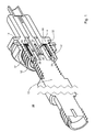
- Figure 1 is an isometric cut-away diagram of a BMA connector including a ground spring according to embodiments of the present invention.
- Figure 2 is an isometric partial cut-away diagram of the BMA connector of Figure 1 , enlarged to see additional detail of the ground spring.
- Figure 3 is top view of a conventional ground spring.
- Figure 4 is a top view of a ground spring according to embodiments of the present invention.
- Figure 5 is a side view of the ground spring of Figure 3 .
- Figure 6 is a block diagram of a test and measurement device including a ground spring according to embodiments of the invention.
- FIGS 1 and 2 are isometric cut-away diagrams of a BMA connector 10 including a ground spring according to embodiments of the present invention.
- the BMA connector 10 includes a male portion 12 and female portion 14, which may be manually separated from one another or connected to one another.
- the female portion 14 is mounted to test and measurement equipment and the male portion 12 is removably connected to the female portion.
- the male portion 12 of the BMA connector may also be called a probe.
- a male pin 20 of the male portion 12 is received in a corresponding receiver 22 on the female portion 14.
- a ground 30 of the male portion 12 includes a side ground 32 and an end ground 34. When inserted, the side ground 32 contacts a barrel spring 42 ( Fig.1 ), as illustrated. The end ground 34 of the male portion 12 contacts a ground spring 44. As described above, it is important that the ground spring 44 makes a good ground connection to the male portion 12 of the BMA connector 10 so that the ground signal may be correctly interpreted by the test and measurement device to which the BMA connector 10 is coupled.
- FIG 3 is top view of a conventional ground spring 70.
- the ground spring 70 includes an annular portion 72 and a series of extensions 74. Although not illustrated, the extensions 74 are dished from the annular portion 72.
- the extensions 74 tend to yield. In other words, the stress of inserting the male portion of the BMA connector forces the extensions 74 to flex beyond their elastic limit, i.e., beyond the limit from which they will return to their original position upon unloading.
- the extensions 74 are flexed beyond this limit, they permanently deform, and fail to make good ground contact with the male portion 12 of the BMA connector 10. This causes signal dropouts in the measured signal. Some of the dropouts may be caused by not all of the extensions 74 being able to contact the male portion 12 of the BMA connector 10 due to the previous yielding.
- FIG 4 is a top view of a ground spring 100 according to embodiments of the present invention.
- the ground spring 100 has the same external shape and dimensions as the conventional spring 70, and fits within a standard BMA connector without modification.
- the ground spring 100 includes a generally annular base portion 102, and a number of elongated spring fingers 110 extending from the base portion.
- the fingers 110 extend generally radially inwardly from the base portion 102 and have inner end faces 112 that together define a substantially circular opening in a center portion of the ground spring 100.
- Each of the fingers 110 has a tapered shape including a wider base portion 114 end and a narrower inner end portion 115.
- Each of the fingers 110 has a longitudinal axis 120 that is aslant relative to a reference line 125 extending from the center 130 of the ground spring 100 to a center of the base portion 114 of each finger.
- the angle between the reference line 125 and the longitudinal axis 120 is between 30 and 50 degrees, and preferably approximately 40 degrees.
- other offset angles also operate according to the same principles as disclosed herein and selection of a particular angle may be an implementation choice.
- the fingers 110 of the ground spring 100 are much longer, which reduces the stress of the fingers 110 when the male portion 12 of the BMA connector 10 is inserted and contacts the spring 100.
- the ground spring 100 is preferably made from Beryllium Copper, and may further be coated by a layer of gold using conventional methods.
- the ground spring is preferably approximately .0025 inches thick at both the base portion 114 and the inner end 115.
- the ground spring 100 may be formed by any appropriate method, and preferably by using Electric Discharge Machining (EDM) techniques. After the general shape of the spring 100 is cut by EDM, it is shaped, such as by dishing, to a shape described below with reference to Figure 5 . After being dished, the ground spring 100 is chemically etched, then heat treated to increase the total strength of the spring. Finally, the ground spring 100 may be plated by gold having a nickel underplate.
- EDM Electric Discharge Machining
- a gap 120 between two adjacent fingers 110 includes a rounded end 122 and an open end 124 that opens to the center portion of the ground spring 100.
- the gap 120 narrows as the gap extends from the annular base portion 102 toward the center 130 of the ground spring.
- the ground spring 100 may be formed to have a generally dished shape formed by bending the fingers 110 at a transition ring 104 ( Figure 4 ).
- the thickness 140 of the dished shape is approximately .014 to .017 inches.
- the fingers 110 are preferably generally flat.
- the fingers 110 extend along a plane from the inner edge of the transition ring 104 toward the center 130 of the ground spring 100, and the dish shape of the ground spring is caused by deforming the spring in the transition ring 104.
- the fingers 110 are also flat across a width of each finger, so that there is no rounded shape across a transverse plane of the fingers 110.
- This shape helps spread the stress of inserting the male portion 12 of the BMA connector 10 across the entire spring 100, and keeps the fingers 110 within the elastic limit of the spring. This allows the spring 100 to be used hundreds or thousands of times, and returns to the original deflection after the BMA connector has been removed.
- FIG. 6 is a block diagram of a test and measurement device 600 including a ground spring according to embodiments of the invention.
- the test and measurement device includes a BMA connector 610, into which a probe 620, or the male portion of a BMA connecter may be inserted.
- the BMA connector 610 includes the ground spring 100 of Figure 4 to contact a male portion of the BMA connector and make ground contact.
- a signal to be tested by the measurement device 600 is carried from whatever is being tested along a test lead to the receiving BMA connector 610.
- a processor 640 performs various operations and processes on the signal, or on other signals (not pictured). The processes may be controlled by a user through a user interface 630 using conventional means. The output of the test and measurement device 600 may then be directed to a display 650, or to other forms of output for use by a user of the device 600.
Abstract
Description
- This application claims the benefit of
U.S. provisional application no. 61/582,967, filed January 4, 2012 U.S. serial no. 13/594,044, filed August 24, 2012 - This disclosure relates to test and measurement equipment, and, more particularly, to a high precision ground spring for test and measurement equipment that allows the instrument to accurately measure high frequency signals.
- Test and measurement equipment receives signals through test leads and performs measurements on them. Leads are coupled to the equipment through connectors. One form of connector is called a BMA lead, which stands for "BlindMate A" connectors, which are RF (Radio Frequency) connectors that receive test signals having high frequencies, such as microwave radio frequencies in the .3GHz to 300 GHz range.
- A ground spring is a spring that contacts the ground of a BMA connector. The ground spring function is to provide an electrical connection to the BMA connector, so that signals may be measured relative to this ground. Present ground springs suffer from reliability problems. They oftentimes fail to make adequate connection to the ground connection, which causes data dropouts on the tested signal, especially in signals having frequencies higher than approximately 20GHz. Present ground springs also tend to lose their spring function after only a few cycles of connector insertion and removal.
- Embodiments of the invention address these and other problems in the prior art.
- Accordingly, the present invention is for a ground spring for receiving a ground end of a high-frequency test probe. The ground spring has a generally annular base portion and a plurality of elongated spring fingers extending from the base portion. The elongated spring fingers generally radiate inwardly and have inner end faces that together define a substantially circular opening in a center of the ground spring. Each of the fingers has a tapered shape including a wider base end and a narrower inner end. Each of the fingers has a longitudinal axis that is aslant relative to a reference line extending from a center of the ground spring to a center of the base end of each finger.
- Each adjacent finger has a gap formed there between that narrows as the gap extends from the annular base portion toward the center of the ground spring. The ground spring has a generally dished shape having a height of approximately 0.017 inches. Each of the elongated spring fingers extending from the base portion is substantially planar. The ground spring is preferably formed from Beryllium Copper having gold plating thereon with the elongate spring fingers being approximately 0.0025 inches thick. Each of the elongate spring fingers has a longitudinal axis that is aslant from a reference line extending from the center of the ground spring to a center of the base portion by approximately 40 degrees.
- The ground spring is disposed in a female portion of a BMA connector having a generally cylindrical receiver portion for receiving a male portion of a matched BMA connector. The ground spring receives a ground end of the male portion of the matched BMA connector. The ground spring has a generally annular base portion and a plurality of elongated spring fingers extending from the base portion. The elongated spring fingers generally radiate inwardly and have inner end faces that together define a substantially circular opening in a center of the ground spring. Each of the fingers has a tapered shape including a wider base end and a narrower inner end. Each of the fingers has a longitudinal axis that is aslant relative to a reference line extending from a center of the ground spring to a center of the base end of each finger
- The ground spring is implemented in a test and measurement instrument having a processor structured to accept an input signal and generate an output therefrom. The test and measurement instrument has a display unit structured to display the output from the processor and an input unit including a female portion of a BMA connector. The female portion of the BMA connector has a generally cylindrical receiver portion for receiving a male portion of a matched BMA connector and the ground spring for receiving a ground end of the male portion of the matched BMA connector. The ground spring has a generally annular base portion and a plurality of elongated spring fingers extending from the base portion. The elongated spring fingers generally radiate inwardly and have inner end faces that together define a substantially circular opening in a center of the ground spring. Each of the fingers has a tapered shape including a wider base end and a narrower inner end. Each of the fingers has a longitudinal axis that is aslant relative to a reference line extending from a center of the ground spring to a center of the base end of each finger.
- The objects, advantages and novel features of the present invention are apparent from the following detailed description when read in conjunction with appended claims and attached drawings.
- BRIEF DESCRIPTION OF THE DRAWINGS
-
Figure 1 is an isometric cut-away diagram of a BMA connector including a ground spring according to embodiments of the present invention. -
Figure 2 is an isometric partial cut-away diagram of the BMA connector ofFigure 1 , enlarged to see additional detail of the ground spring. -
Figure 3 is top view of a conventional ground spring. -
Figure 4 is a top view of a ground spring according to embodiments of the present invention. -
Figure 5 is a side view of the ground spring ofFigure 3 . -
Figure 6 is a block diagram of a test and measurement device including a ground spring according to embodiments of the invention. -
Figures 1 and2 are isometric cut-away diagrams of aBMA connector 10 including a ground spring according to embodiments of the present invention. - The
BMA connector 10 includes amale portion 12 andfemale portion 14, which may be manually separated from one another or connected to one another. Typically thefemale portion 14 is mounted to test and measurement equipment and themale portion 12 is removably connected to the female portion. Themale portion 12 of the BMA connector may also be called a probe. - When connecting the
male portion 12 of theBMA connector 10 to thefemale portion 14, the male portion is inserted, or plugged into, the female portion. Amale pin 20 of themale portion 12 is received in acorresponding receiver 22 on thefemale portion 14. Aground 30 of themale portion 12 includes aside ground 32 and anend ground 34. When inserted, theside ground 32 contacts a barrel spring 42 (Fig.1 ), as illustrated. Theend ground 34 of themale portion 12 contacts aground spring 44. As described above, it is important that theground spring 44 makes a good ground connection to themale portion 12 of theBMA connector 10 so that the ground signal may be correctly interpreted by the test and measurement device to which theBMA connector 10 is coupled. - As better illustrated in
Figure 2 , when themale portion 12 of theBMA connector 10 is fully inserted into the female portion, theend ground 34 makes physical contact with theground spring 44. This causes the fingers of theground spring 44, described in detail below, to flex. The return spring force of the fingers of theground spring 44 holds the ground spring in constant contact with theend ground 34 of themale portion 12 of the BMA connector, making for a solid electrical connection to be used by the test and measurement device. -
Figure 3 is top view of aconventional ground spring 70. Theground spring 70 includes anannular portion 72 and a series ofextensions 74. Although not illustrated, theextensions 74 are dished from theannular portion 72. When themale portion 12 of theBMA connector 10 is inserted into thefemale portion 14 and received at theconventional ground spring 70, theextensions 74 tend to yield. In other words, the stress of inserting the male portion of the BMA connector forces theextensions 74 to flex beyond their elastic limit, i.e., beyond the limit from which they will return to their original position upon unloading. When theextensions 74 are flexed beyond this limit, they permanently deform, and fail to make good ground contact with themale portion 12 of theBMA connector 10. This causes signal dropouts in the measured signal. Some of the dropouts may be caused by not all of theextensions 74 being able to contact themale portion 12 of theBMA connector 10 due to the previous yielding. -
Figure 4 is a top view of aground spring 100 according to embodiments of the present invention. Theground spring 100 has the same external shape and dimensions as theconventional spring 70, and fits within a standard BMA connector without modification. - The
ground spring 100 includes a generallyannular base portion 102, and a number ofelongated spring fingers 110 extending from the base portion. Thefingers 110 extend generally radially inwardly from thebase portion 102 and have inner end faces 112 that together define a substantially circular opening in a center portion of theground spring 100. Each of thefingers 110 has a tapered shape including awider base portion 114 end and a narrowerinner end portion 115. - Each of the
fingers 110 has alongitudinal axis 120 that is aslant relative to areference line 125 extending from thecenter 130 of theground spring 100 to a center of thebase portion 114 of each finger. In a preferred embodiment, the angle between thereference line 125 and thelongitudinal axis 120 is between 30 and 50 degrees, and preferably approximately 40 degrees. Of course, other offset angles also operate according to the same principles as disclosed herein and selection of a particular angle may be an implementation choice. - Note that compared to the
extensions 74 ofFigure 2 , thefingers 110 of theground spring 100 are much longer, which reduces the stress of thefingers 110 when themale portion 12 of theBMA connector 10 is inserted and contacts thespring 100. - The
ground spring 100 is preferably made from Beryllium Copper, and may further be coated by a layer of gold using conventional methods. The ground spring is preferably approximately .0025 inches thick at both thebase portion 114 and theinner end 115. Theground spring 100 may be formed by any appropriate method, and preferably by using Electric Discharge Machining (EDM) techniques. After the general shape of thespring 100 is cut by EDM, it is shaped, such as by dishing, to a shape described below with reference toFigure 5 . After being dished, theground spring 100 is chemically etched, then heat treated to increase the total strength of the spring. Finally, theground spring 100 may be plated by gold having a nickel underplate. - A
gap 120 between twoadjacent fingers 110 includes arounded end 122 and anopen end 124 that opens to the center portion of theground spring 100. Thegap 120 narrows as the gap extends from theannular base portion 102 toward thecenter 130 of the ground spring. - As illustrated in
Figure 5 , theground spring 100 may be formed to have a generally dished shape formed by bending thefingers 110 at a transition ring 104 (Figure 4 ). In one embodiment thethickness 140 of the dished shape is approximately .014 to .017 inches. From an inner edge of thetransition ring 104, thefingers 110 are preferably generally flat. In other words, thefingers 110 extend along a plane from the inner edge of thetransition ring 104 toward thecenter 130 of theground spring 100, and the dish shape of the ground spring is caused by deforming the spring in thetransition ring 104. Preferably thefingers 110 are also flat across a width of each finger, so that there is no rounded shape across a transverse plane of thefingers 110. This shape helps spread the stress of inserting themale portion 12 of theBMA connector 10 across theentire spring 100, and keeps thefingers 110 within the elastic limit of the spring. This allows thespring 100 to be used hundreds or thousands of times, and returns to the original deflection after the BMA connector has been removed. -
Figure 6 is a block diagram of a test andmeasurement device 600 including a ground spring according to embodiments of the invention. The test and measurement device includes aBMA connector 610, into which aprobe 620, or the male portion of a BMA connecter may be inserted. TheBMA connector 610 includes theground spring 100 ofFigure 4 to contact a male portion of the BMA connector and make ground contact. A signal to be tested by themeasurement device 600 is carried from whatever is being tested along a test lead to the receivingBMA connector 610. - Once the test and
measurement device 600 receives a signal under test, aprocessor 640 performs various operations and processes on the signal, or on other signals (not pictured). The processes may be controlled by a user through auser interface 630 using conventional means. The output of the test andmeasurement device 600 may then be directed to adisplay 650, or to other forms of output for use by a user of thedevice 600. - Having described and illustrated the principles of the invention with reference to illustrated embodiments, it will be recognized that the illustrated embodiments may be modified in arrangement and detail without departing from such principles, and may be combined in any desired manner. And although the foregoing discussion has focused on particular embodiments, other configurations are contemplated. In particular, even though expressions such as "according to an embodiment of the invention" or the like are used herein, these phrases are meant to generally reference embodiment possibilities, and are not intended to limit the invention to particular embodiment configurations. As used herein, these terms may reference the same or different embodiments that are combinable into other embodiments.
- Consequently, in view of the wide variety of permutations to the embodiments described herein, this detailed description and accompanying material is intended to be illustrative only, and should not be taken as limiting the scope of the invention. What is claimed as the invention, therefore, is all such modifications as may come within the scope of the following claims.
Claims (11)
- A ground spring for receiving a ground end of a high-frequency test probe, the ground spring comprising:a generally annular base portion; anda plurality of elongated spring fingers extending from the base portion generally radially inwardly and having inner end faces that together define a substantially circular opening in a center of the ground spring, each of the fingers having a tapered shape including a wider base end and a narrower inner end, and each of the fingers having a longitudinal axis that is aslant relative to a reference line extending from a center of the ground spring to a center of the base end of each finger.
- The ground spring of claim 1 in which a gap between two adjacent fingers narrows as the gap extends from the annular base portion toward the center of the ground spring.
- The ground spring of claim 1 or 2 in which the spring has a generally dished shape.
- The ground spring of any preceding claim in which the dished height is approximately 0.017 inches.
- The ground spring of any preceding claim in which the ground spring is formed from Beryllium Copper.
- The ground spring of any preceding claim in which the fingers are approximately 0.0025 inches thick.
- The ground spring of any preceding claim further comprising gold plating.
- The ground spring of any preceding claim in which the fingers are substantially planar.
- The ground spring of any preceding claim in which the longitudinal axis is aslant from the reference line by approximately 40 degrees.
- A female portion of a BMA connector comprising:a generally cylindrical receiver portion for receiving a male portion of a matched BMA connector; anda ground spring as claimed in any preceding claim.
- A test and measurement instrument comprising:a processor structured to accept an input signal and generate an output therefrom;a display unit structured to display the output from the processor; andan input unit including a female portion of a BMA connector as claimed in claim 10.
Applications Claiming Priority (2)
| Application Number | Priority Date | Filing Date | Title |
|---|---|---|---|
| US201261582967P | 2012-01-04 | 2012-01-04 | |
| US13/594,044 US8936485B2 (en) | 2012-01-04 | 2012-08-24 | Ground spring with strain relief |
Publications (3)
| Publication Number | Publication Date |
|---|---|
| EP2613413A2 true EP2613413A2 (en) | 2013-07-10 |
| EP2613413A3 EP2613413A3 (en) | 2014-10-29 |
| EP2613413B1 EP2613413B1 (en) | 2016-03-30 |
Family
ID=47522382
Family Applications (1)
| Application Number | Title | Priority Date | Filing Date |
|---|---|---|---|
| EP13150184.3A Active EP2613413B1 (en) | 2012-01-04 | 2013-01-03 | Ground spring with strain relief |
Country Status (6)
| Country | Link |
|---|---|
| US (1) | US8936485B2 (en) |
| EP (1) | EP2613413B1 (en) |
| JP (1) | JP6043984B2 (en) |
| KR (1) | KR101956650B1 (en) |
| CN (1) | CN103199388B (en) |
| TW (1) | TWI580129B (en) |
Families Citing this family (6)
| Publication number | Priority date | Publication date | Assignee | Title |
|---|---|---|---|---|
| US9570849B2 (en) * | 2013-11-05 | 2017-02-14 | Commscope Technologies Llc | Float plate for blind matable electrical cable connectors |
| US9661753B1 (en) | 2016-12-01 | 2017-05-23 | Harris Corporation | Coaxial to planar strain relief appliance and method |
| DE102017130015B4 (en) * | 2017-12-14 | 2019-11-14 | Ingun Prüfmittelbau Gmbh | Radio frequency test plug device, radio frequency test system and use of such |
| CN108736203A (en) * | 2018-07-28 | 2018-11-02 | 中国电子科技集团公司第四十研究所 | A kind of high-performance floating blind inserting radio frequency coaxial connector |
| US10886588B2 (en) | 2018-09-26 | 2021-01-05 | Keysight Technologies, Inc. | High dynamic range probe using pole-zero cancellation |
| CN113646966B (en) * | 2018-10-15 | 2023-04-11 | 株式会社Kmw | Cavity filter |
Family Cites Families (17)
| Publication number | Priority date | Publication date | Assignee | Title |
|---|---|---|---|---|
| US3678445A (en) | 1970-07-31 | 1972-07-18 | Itt | Electrical connector shield |
| JPS546066Y2 (en) * | 1974-11-25 | 1979-03-19 | ||
| JP2976326B2 (en) * | 1995-06-02 | 1999-11-10 | 日本航空電子工業株式会社 | Contact for BGA |
| US5830010A (en) * | 1996-10-11 | 1998-11-03 | Molex Incorporated | Impedance matched cable assembly |
| US5871371A (en) * | 1996-12-19 | 1999-02-16 | The Whitaker Corporation | High density circular connector |
| JP3035541B1 (en) * | 1999-03-19 | 2000-04-24 | エスエムケイ株式会社 | Floating connector |
| US6383031B1 (en) * | 2000-03-31 | 2002-05-07 | Tektronix, Inc. | Keyed electronic interconnect device for high speed signal and data transmission |
| JP4579663B2 (en) * | 2004-12-10 | 2010-11-10 | マスプロ電工株式会社 | Coaxial cable connector and electronic device box |
| US7116120B1 (en) * | 2005-09-07 | 2006-10-03 | Agilent Technologies, Inc. | Clamping test fixture for a high frequency miniature probe assembly |
| US7819698B2 (en) * | 2007-08-22 | 2010-10-26 | Andrew Llc | Sealed inner conductor contact for coaxial cable connector |
| US8075337B2 (en) * | 2008-09-30 | 2011-12-13 | Belden Inc. | Cable connector |
| JP5133196B2 (en) * | 2008-10-10 | 2013-01-30 | モレックス インコーポレイテド | Probe connector |
| JP4873759B2 (en) | 2009-12-25 | 2012-02-08 | Smk株式会社 | Method for fitting receptacle and contact probe and contact probe used in this method |
| JP5043962B2 (en) | 2010-01-12 | 2012-10-10 | 三菱電機株式会社 | Electronic substrate inspection apparatus and electronic substrate inspection method |
| CN101814671B (en) * | 2010-03-24 | 2012-01-04 | 中航光电科技股份有限公司 | Connector |
| CN201717453U (en) * | 2010-05-27 | 2011-01-19 | 芯通科技(成都)有限公司 | Shielding gasket for SMA radio frequency connecting piece |
| US8636529B2 (en) * | 2011-02-17 | 2014-01-28 | Corning Gilbert Inc. | Blind mate interconnect and contact |
-
2012
- 2012-08-24 US US13/594,044 patent/US8936485B2/en active Active
- 2012-12-27 JP JP2012285502A patent/JP6043984B2/en active Active
- 2012-12-27 TW TW101150510A patent/TWI580129B/en active
-
2013
- 2013-01-03 EP EP13150184.3A patent/EP2613413B1/en active Active
- 2013-01-03 KR KR1020130000603A patent/KR101956650B1/en active IP Right Grant
- 2013-01-04 CN CN201310001251.7A patent/CN103199388B/en active Active
Non-Patent Citations (1)
| Title |
|---|
| None |
Also Published As
| Publication number | Publication date |
|---|---|
| EP2613413B1 (en) | 2016-03-30 |
| JP2013140795A (en) | 2013-07-18 |
| TW201342737A (en) | 2013-10-16 |
| US8936485B2 (en) | 2015-01-20 |
| CN103199388A (en) | 2013-07-10 |
| KR20130080460A (en) | 2013-07-12 |
| KR101956650B1 (en) | 2019-03-11 |
| TWI580129B (en) | 2017-04-21 |
| JP6043984B2 (en) | 2016-12-14 |
| EP2613413A3 (en) | 2014-10-29 |
| CN103199388B (en) | 2017-06-06 |
| US20130171868A1 (en) | 2013-07-04 |
Similar Documents
| Publication | Publication Date | Title |
|---|---|---|
| US8936485B2 (en) | Ground spring with strain relief | |
| US11088051B2 (en) | Test socket assembly and related methods | |
| US8758066B2 (en) | Electrical connector with insulation member | |
| US7256593B2 (en) | Electrical contact probe with compliant internal interconnect | |
| EP3056912B1 (en) | High frequency probe tip | |
| US20080088331A1 (en) | Socket for test | |
| JP4113343B2 (en) | Probe tip adapter for measurement probe | |
| US20100015850A1 (en) | Low-profile mounted push-on connector | |
| TW200915655A (en) | Spring loaded microwave interconnector | |
| WO2011087763A1 (en) | Terminal for flat test probe | |
| US9917399B2 (en) | Reduced stress electrical connector | |
| CN106133531B (en) | Contact arrangement, in particular HF measuring head | |
| KR20180010935A (en) | Connection Pin of Plate Folding Type | |
| EP2555002B1 (en) | Self-retaining via probe | |
| US7768280B1 (en) | Apparatus for a low-cost semiconductor test interface system | |
| US10119992B2 (en) | High impedance compliant probe tip | |
| EP2687858B1 (en) | Probing tip for a signal acquisition probe | |
| JP2019200209A (en) | Test probe chip and resistance element |
Legal Events
| Date | Code | Title | Description |
|---|---|---|---|
| PUAI | Public reference made under article 153(3) epc to a published international application that has entered the european phase |
Free format text: ORIGINAL CODE: 0009012 |
|
| AK | Designated contracting states |
Kind code of ref document: A2 Designated state(s): AL AT BE BG CH CY CZ DE DK EE ES FI FR GB GR HR HU IE IS IT LI LT LU LV MC MK MT NL NO PL PT RO RS SE SI SK SM TR |
|
| AX | Request for extension of the european patent |
Extension state: BA ME |
|
| RAP1 | Party data changed (applicant data changed or rights of an application transferred) |
Owner name: TEKTRONIX, INC. |
|
| PUAL | Search report despatched |
Free format text: ORIGINAL CODE: 0009013 |
|
| AK | Designated contracting states |
Kind code of ref document: A3 Designated state(s): AL AT BE BG CH CY CZ DE DK EE ES FI FR GB GR HR HU IE IS IT LI LT LU LV MC MK MT NL NO PL PT RO RS SE SI SK SM TR |
|
| AX | Request for extension of the european patent |
Extension state: BA ME |
|
| RIC1 | Information provided on ipc code assigned before grant |
Ipc: H01R 13/6583 20110101AFI20140926BHEP Ipc: H01R 9/05 20060101ALI20140926BHEP |
|
| 17P | Request for examination filed |
Effective date: 20150428 |
|
| RBV | Designated contracting states (corrected) |
Designated state(s): AL AT BE BG CH CY CZ DE DK EE ES FI FR GB GR HR HU IE IS IT LI LT LU LV MC MK MT NL NO PL PT RO RS SE SI SK SM TR |
|
| GRAP | Despatch of communication of intention to grant a patent |
Free format text: ORIGINAL CODE: EPIDOSNIGR1 |
|
| INTG | Intention to grant announced |
Effective date: 20150803 |
|
| GRAS | Grant fee paid |
Free format text: ORIGINAL CODE: EPIDOSNIGR3 |
|
| GRAA | (expected) grant |
Free format text: ORIGINAL CODE: 0009210 |
|
| AK | Designated contracting states |
Kind code of ref document: B1 Designated state(s): AL AT BE BG CH CY CZ DE DK EE ES FI FR GB GR HR HU IE IS IT LI LT LU LV MC MK MT NL NO PL PT RO RS SE SI SK SM TR |
|
| REG | Reference to a national code |
Ref country code: GB Ref legal event code: FG4D |
|
| REG | Reference to a national code |
Ref country code: CH Ref legal event code: EP |
|
| REG | Reference to a national code |
Ref country code: AT Ref legal event code: REF Ref document number: 786295 Country of ref document: AT Kind code of ref document: T Effective date: 20160415 |
|
| REG | Reference to a national code |
Ref country code: IE Ref legal event code: FG4D |
|
| REG | Reference to a national code |
Ref country code: DE Ref legal event code: R096 Ref document number: 602013005812 Country of ref document: DE |
|
| REG | Reference to a national code |
Ref country code: LT Ref legal event code: MG4D |
|
| PG25 | Lapsed in a contracting state [announced via postgrant information from national office to epo] |
Ref country code: FI Free format text: LAPSE BECAUSE OF FAILURE TO SUBMIT A TRANSLATION OF THE DESCRIPTION OR TO PAY THE FEE WITHIN THE PRESCRIBED TIME-LIMIT Effective date: 20160330 Ref country code: NO Free format text: LAPSE BECAUSE OF FAILURE TO SUBMIT A TRANSLATION OF THE DESCRIPTION OR TO PAY THE FEE WITHIN THE PRESCRIBED TIME-LIMIT Effective date: 20160630 Ref country code: HR Free format text: LAPSE BECAUSE OF FAILURE TO SUBMIT A TRANSLATION OF THE DESCRIPTION OR TO PAY THE FEE WITHIN THE PRESCRIBED TIME-LIMIT Effective date: 20160330 Ref country code: GR Free format text: LAPSE BECAUSE OF FAILURE TO SUBMIT A TRANSLATION OF THE DESCRIPTION OR TO PAY THE FEE WITHIN THE PRESCRIBED TIME-LIMIT Effective date: 20160701 |
|
| REG | Reference to a national code |
Ref country code: NL Ref legal event code: MP Effective date: 20160330 |
|
| REG | Reference to a national code |
Ref country code: AT Ref legal event code: MK05 Ref document number: 786295 Country of ref document: AT Kind code of ref document: T Effective date: 20160330 |
|
| PG25 | Lapsed in a contracting state [announced via postgrant information from national office to epo] |
Ref country code: LT Free format text: LAPSE BECAUSE OF FAILURE TO SUBMIT A TRANSLATION OF THE DESCRIPTION OR TO PAY THE FEE WITHIN THE PRESCRIBED TIME-LIMIT Effective date: 20160330 Ref country code: LV Free format text: LAPSE BECAUSE OF FAILURE TO SUBMIT A TRANSLATION OF THE DESCRIPTION OR TO PAY THE FEE WITHIN THE PRESCRIBED TIME-LIMIT Effective date: 20160330 Ref country code: SE Free format text: LAPSE BECAUSE OF FAILURE TO SUBMIT A TRANSLATION OF THE DESCRIPTION OR TO PAY THE FEE WITHIN THE PRESCRIBED TIME-LIMIT Effective date: 20160330 Ref country code: RS Free format text: LAPSE BECAUSE OF FAILURE TO SUBMIT A TRANSLATION OF THE DESCRIPTION OR TO PAY THE FEE WITHIN THE PRESCRIBED TIME-LIMIT Effective date: 20160330 |
|
| PG25 | Lapsed in a contracting state [announced via postgrant information from national office to epo] |
Ref country code: NL Free format text: LAPSE BECAUSE OF FAILURE TO SUBMIT A TRANSLATION OF THE DESCRIPTION OR TO PAY THE FEE WITHIN THE PRESCRIBED TIME-LIMIT Effective date: 20160330 |
|
| PG25 | Lapsed in a contracting state [announced via postgrant information from national office to epo] |
Ref country code: EE Free format text: LAPSE BECAUSE OF FAILURE TO SUBMIT A TRANSLATION OF THE DESCRIPTION OR TO PAY THE FEE WITHIN THE PRESCRIBED TIME-LIMIT Effective date: 20160330 Ref country code: PL Free format text: LAPSE BECAUSE OF FAILURE TO SUBMIT A TRANSLATION OF THE DESCRIPTION OR TO PAY THE FEE WITHIN THE PRESCRIBED TIME-LIMIT Effective date: 20160330 Ref country code: IS Free format text: LAPSE BECAUSE OF FAILURE TO SUBMIT A TRANSLATION OF THE DESCRIPTION OR TO PAY THE FEE WITHIN THE PRESCRIBED TIME-LIMIT Effective date: 20160730 |
|
| PG25 | Lapsed in a contracting state [announced via postgrant information from national office to epo] |
Ref country code: SK Free format text: LAPSE BECAUSE OF FAILURE TO SUBMIT A TRANSLATION OF THE DESCRIPTION OR TO PAY THE FEE WITHIN THE PRESCRIBED TIME-LIMIT Effective date: 20160330 Ref country code: CZ Free format text: LAPSE BECAUSE OF FAILURE TO SUBMIT A TRANSLATION OF THE DESCRIPTION OR TO PAY THE FEE WITHIN THE PRESCRIBED TIME-LIMIT Effective date: 20160330 Ref country code: RO Free format text: LAPSE BECAUSE OF FAILURE TO SUBMIT A TRANSLATION OF THE DESCRIPTION OR TO PAY THE FEE WITHIN THE PRESCRIBED TIME-LIMIT Effective date: 20160330 Ref country code: AT Free format text: LAPSE BECAUSE OF FAILURE TO SUBMIT A TRANSLATION OF THE DESCRIPTION OR TO PAY THE FEE WITHIN THE PRESCRIBED TIME-LIMIT Effective date: 20160330 Ref country code: SM Free format text: LAPSE BECAUSE OF FAILURE TO SUBMIT A TRANSLATION OF THE DESCRIPTION OR TO PAY THE FEE WITHIN THE PRESCRIBED TIME-LIMIT Effective date: 20160330 Ref country code: PT Free format text: LAPSE BECAUSE OF FAILURE TO SUBMIT A TRANSLATION OF THE DESCRIPTION OR TO PAY THE FEE WITHIN THE PRESCRIBED TIME-LIMIT Effective date: 20160801 Ref country code: ES Free format text: LAPSE BECAUSE OF FAILURE TO SUBMIT A TRANSLATION OF THE DESCRIPTION OR TO PAY THE FEE WITHIN THE PRESCRIBED TIME-LIMIT Effective date: 20160330 |
|
| PG25 | Lapsed in a contracting state [announced via postgrant information from national office to epo] |
Ref country code: BE Free format text: LAPSE BECAUSE OF FAILURE TO SUBMIT A TRANSLATION OF THE DESCRIPTION OR TO PAY THE FEE WITHIN THE PRESCRIBED TIME-LIMIT Effective date: 20160330 Ref country code: IT Free format text: LAPSE BECAUSE OF FAILURE TO SUBMIT A TRANSLATION OF THE DESCRIPTION OR TO PAY THE FEE WITHIN THE PRESCRIBED TIME-LIMIT Effective date: 20160330 |
|
| REG | Reference to a national code |
Ref country code: DE Ref legal event code: R097 Ref document number: 602013005812 Country of ref document: DE |
|
| PG25 | Lapsed in a contracting state [announced via postgrant information from national office to epo] |
Ref country code: DK Free format text: LAPSE BECAUSE OF FAILURE TO SUBMIT A TRANSLATION OF THE DESCRIPTION OR TO PAY THE FEE WITHIN THE PRESCRIBED TIME-LIMIT Effective date: 20160330 |
|
| PLBE | No opposition filed within time limit |
Free format text: ORIGINAL CODE: 0009261 |
|
| STAA | Information on the status of an ep patent application or granted ep patent |
Free format text: STATUS: NO OPPOSITION FILED WITHIN TIME LIMIT |
|
| 26N | No opposition filed |
Effective date: 20170103 |
|
| PG25 | Lapsed in a contracting state [announced via postgrant information from national office to epo] |
Ref country code: SI Free format text: LAPSE BECAUSE OF FAILURE TO SUBMIT A TRANSLATION OF THE DESCRIPTION OR TO PAY THE FEE WITHIN THE PRESCRIBED TIME-LIMIT Effective date: 20160330 |
|
| REG | Reference to a national code |
Ref country code: CH Ref legal event code: PL |
|
| PG25 | Lapsed in a contracting state [announced via postgrant information from national office to epo] |
Ref country code: MC Free format text: LAPSE BECAUSE OF FAILURE TO SUBMIT A TRANSLATION OF THE DESCRIPTION OR TO PAY THE FEE WITHIN THE PRESCRIBED TIME-LIMIT Effective date: 20160330 |
|
| REG | Reference to a national code |
Ref country code: FR Ref legal event code: ST Effective date: 20170929 |
|
| PG25 | Lapsed in a contracting state [announced via postgrant information from national office to epo] |
Ref country code: LI Free format text: LAPSE BECAUSE OF NON-PAYMENT OF DUE FEES Effective date: 20170131 Ref country code: CH Free format text: LAPSE BECAUSE OF NON-PAYMENT OF DUE FEES Effective date: 20170131 Ref country code: FR Free format text: LAPSE BECAUSE OF NON-PAYMENT OF DUE FEES Effective date: 20170131 |
|
| REG | Reference to a national code |
Ref country code: IE Ref legal event code: MM4A |
|
| PG25 | Lapsed in a contracting state [announced via postgrant information from national office to epo] |
Ref country code: LU Free format text: LAPSE BECAUSE OF NON-PAYMENT OF DUE FEES Effective date: 20170103 |
|
| PG25 | Lapsed in a contracting state [announced via postgrant information from national office to epo] |
Ref country code: IE Free format text: LAPSE BECAUSE OF NON-PAYMENT OF DUE FEES Effective date: 20170103 |
|
| PG25 | Lapsed in a contracting state [announced via postgrant information from national office to epo] |
Ref country code: MT Free format text: LAPSE BECAUSE OF NON-PAYMENT OF DUE FEES Effective date: 20170103 |
|
| PG25 | Lapsed in a contracting state [announced via postgrant information from national office to epo] |
Ref country code: AL Free format text: LAPSE BECAUSE OF FAILURE TO SUBMIT A TRANSLATION OF THE DESCRIPTION OR TO PAY THE FEE WITHIN THE PRESCRIBED TIME-LIMIT Effective date: 20160330 |
|
| PGFP | Annual fee paid to national office [announced via postgrant information from national office to epo] |
Ref country code: BE Payment date: 20190215 Year of fee payment: 6 |
|
| PG25 | Lapsed in a contracting state [announced via postgrant information from national office to epo] |
Ref country code: HU Free format text: LAPSE BECAUSE OF FAILURE TO SUBMIT A TRANSLATION OF THE DESCRIPTION OR TO PAY THE FEE WITHIN THE PRESCRIBED TIME-LIMIT; INVALID AB INITIO Effective date: 20130103 |
|
| PG25 | Lapsed in a contracting state [announced via postgrant information from national office to epo] |
Ref country code: BG Free format text: LAPSE BECAUSE OF FAILURE TO SUBMIT A TRANSLATION OF THE DESCRIPTION OR TO PAY THE FEE WITHIN THE PRESCRIBED TIME-LIMIT Effective date: 20160330 |
|
| PG25 | Lapsed in a contracting state [announced via postgrant information from national office to epo] |
Ref country code: CY Free format text: LAPSE BECAUSE OF NON-PAYMENT OF DUE FEES Effective date: 20160330 |
|
| PG25 | Lapsed in a contracting state [announced via postgrant information from national office to epo] |
Ref country code: MK Free format text: LAPSE BECAUSE OF FAILURE TO SUBMIT A TRANSLATION OF THE DESCRIPTION OR TO PAY THE FEE WITHIN THE PRESCRIBED TIME-LIMIT Effective date: 20160330 |
|
| PG25 | Lapsed in a contracting state [announced via postgrant information from national office to epo] |
Ref country code: TR Free format text: LAPSE BECAUSE OF FAILURE TO SUBMIT A TRANSLATION OF THE DESCRIPTION OR TO PAY THE FEE WITHIN THE PRESCRIBED TIME-LIMIT Effective date: 20160330 |
|
| GBPC | Gb: european patent ceased through non-payment of renewal fee |
Effective date: 20200103 |
|
| PG25 | Lapsed in a contracting state [announced via postgrant information from national office to epo] |
Ref country code: GB Free format text: LAPSE BECAUSE OF NON-PAYMENT OF DUE FEES Effective date: 20200103 |
|
| PGFP | Annual fee paid to national office [announced via postgrant information from national office to epo] |
Ref country code: DE Payment date: 20230127 Year of fee payment: 11 |
|
| P01 | Opt-out of the competence of the unified patent court (upc) registered |
Effective date: 20230530 |