EP2613283A2 - Informationsvalidierung - Google Patents
Informationsvalidierung Download PDFInfo
- Publication number
- EP2613283A2 EP2613283A2 EP12008205.2A EP12008205A EP2613283A2 EP 2613283 A2 EP2613283 A2 EP 2613283A2 EP 12008205 A EP12008205 A EP 12008205A EP 2613283 A2 EP2613283 A2 EP 2613283A2
- Authority
- EP
- European Patent Office
- Prior art keywords
- fact
- automaton
- validation
- state
- facts
- Prior art date
- Legal status (The legal status is an assumption and is not a legal conclusion. Google has not performed a legal analysis and makes no representation as to the accuracy of the status listed.)
- Ceased
Links
Images


Classifications
-
- G—PHYSICS
- G06—COMPUTING; CALCULATING OR COUNTING
- G06N—COMPUTING ARRANGEMENTS BASED ON SPECIFIC COMPUTATIONAL MODELS
- G06N5/00—Computing arrangements using knowledge-based models
- G06N5/02—Knowledge representation; Symbolic representation
-
- G—PHYSICS
- G06—COMPUTING; CALCULATING OR COUNTING
- G06N—COMPUTING ARRANGEMENTS BASED ON SPECIFIC COMPUTATIONAL MODELS
- G06N5/00—Computing arrangements using knowledge-based models
- G06N5/02—Knowledge representation; Symbolic representation
- G06N5/022—Knowledge engineering; Knowledge acquisition
Definitions
- This invention relates to information validation, and more particularly to content-based knowledge validation using, for example, deterministic finite automata.
- Structured data can be used to graphically display the information to a user or used for programmatically processing.
- Invalid information which may come from different sources, may compromise the quality of structured data.
- Validation of the information may preserve the quality of structured data according to its model, e.g., consolidated model in the business trading network domain.
- this disclosure pertains to content-based validation of knowledge (structured data). It includes the validation of the content of the detected and injected knowledge, as well as its conformance with a given model, e.g. the Consolidated Model.
- the validation includes the validation of (user defined) dependencies of the knowledge.
- This disclosure describes a design and implementation of a system, method, and computer program product that validates the knowledge shown for the trading web of an enterprise according to the Consolidated Model.
- a computer-implemented method for knowledge validation may include identifying a fact for validation.
- a semantic model may be created, the semantic model representing the fact for validation.
- a context associated with the fact may be identified, and an automaton can be created based at least in part on the identified context. The fact can be validated using the automaton.
- a computer program product for knowledge validation may be stored on a tangible, non-transitory media, operable to execute instructions that can include identifying a fact for validation.
- a semantic model may be created, the semantic model representing the fact for validation.
- a context associated with the fact may be identified, and an automaton can be created based at least in part on the identified context. The fact can be validated using the automaton
- Certain implementations of the embodiments can also include identifying a consolidated model.
- the consolidated model can include information about business trading networks within and between companies. The fact for validation may be associated with the consolidated model.
- the automaton is a deterministic finite automaton.
- the deterministic finite automaton may be derived from an epsilon non-deterministic finite automaton.
- the deterministic finite automaton may be defined by one or more of a state, an input symbol, a transition function, a starting state, and a final state.
- the final state can be an accepting state, and the automaton can enter the accepting state after successfully validating the fact.
- the automaton is created based, at least in part on, the semantic model.
- the semantic model further represents fact dependencies associated with the fact.
- the fact to be validated may be a subset of the context.
- creating an automaton based at least in part on the identified context may include creating an automaton for each instance of a model entity.
- the fact may be a Datalog fact.
- the fact may be one or more of a fact, knowledge, or data.
- Certain implementations of the embodiments can also include providing a runtime graphical output identifying error states.
- Certain implementations of the embodiments can also include providing a runtime textual log output identifying errors.
- validating the fact using the automaton can include validating one or more of structure or content of structured data.
- a domain specific language may be used for a programming model to specify a validation program.
- a validation program can be generated from the semantic model.
- the semantic model may be in a domain specific language, and the automaton can be generated at runtime from the semantic model.
- the automaton can be generated automatically by an intelligent algorithm.
- the fact is a fact in a consolidation model, the consolidation model subject to validation by the automaton.
- a Domain Specific Language (DSL) or fluent Application Programming Interface (API) can be used for a programming model to specify a validation program.
- the validation program is generated from, for example, the DSL, and is called a semantic model.
- a runtime model is generated, for example, as an automaton.
- the automaton is automatically generated by intelligent algorithm.
- the runtime model is able to run different evaluation procedures such as top-down, bottom-up or random evaluation of the validation program.
- the approach described herein is designed for efficient storage and loading of data, parallel processing of validation programs, as well as shared memory computing (e.g., concurrency for validation programs defined).
- the approach is applicable for the validation of facts, which may be a part of a Datalog program.
- Datalog facts are structured and thus applicable to the disclosure.
- the techniques described herein are also applicable to complex fact models, e.g., the consolidation model described herein, and the techniques described herein can be used to validate facts for that domain (e.g., model-based validations).
- the validation programs are debuggable to make the validation programming model usable as any other programming language. Debugging can be facilitated by graphical and textual outputs for real-time debugging.
- This disclosure provides for defining a configurable but automatic validation schema as a programming model in the area of regular and context sensitive languages. It allows for domain-specific data quality and allows for various kinds of checks, such as value lists, structural, etc. Validation programs can be written by persons of varying degrees of knowledge in programming.
- States apply to operators of a validation program. These states can be self-defined and thus the techniques described herein can be extended by custom validation operations, such as filter states, length checks, starts with or ends with checks for strings, boundary checks for numeric types, etc.
- example domain Business Trading Web
- subject matter disclosed herein can be applied. It is understood, however, that the subject matter is not limited only to that domain.
- the subject matter described herein can be used for any structured data, including that associated with the consolidation model described below.
- the subject matter described herein is applicable for other domains, such as input to deductive systems, data quality validation for linked data community, process mining, etc.
- the Business Trading Web is a software developed by SAP AG that graphically gives a central overview of the trading networks of enterprises.
- SAP AG SAP AG that graphically gives a central overview of the trading networks of enterprises.
- information about the customer landscape is collected, consolidated and stored in a model, whose logical knowledge representation is implemented in Datalog.
- users can affect the injection of facts by developing their own data extractors and processors, the facts have to be validated according to their content and interdependencies to ensure a consistent knowledge base.
- a programming model based on Deterministic Finite Automata, has been developed. It allows to generically process knowledge encoded in Datalog and it empowers custom extensions to the validation logic.
- FVA Fact Validation Automaton
- the implemented Fact Validation Automaton facilitates the distributed validation of facts in a given context using different validation strategies.
- the validation can be manipulated by the definition of the structure of the facts using a domain-specific language.
- custom states containing validation logic can be implemented.
- this disclosure describes the application of the developed FVA in the context of the Business Trading Web. It evaluates different root causes in this context and shows performance measurements for different validation strategies. Additionally, there is some guidance on debugging, i.e., analyzing the reason for a fact being invalid.
- Enterprises manage their knowledge, which does not only include the skills and competencies of the employees, but also information about the variety of business networks that the enterprise participates in. However, independent of the amount of knowledge that is collected and managed, the benefits of the knowledge are only as good as its quality. The knowledge has to be consistent, thus it needs to be validated.
- the Business Trading Web is a software that collects information about business trading networks within and between companies and stores them in a model (called the Consolidated Model) in order to graphically display them to the user.
- the Consolidated Model a model
- the main topic of this thesis is the content-based validation of knowledge. It includes the validation of the content of the detected and injected knowledge as well as its conformance with the predefined Consolidated Model. This includes the validation of possible dependencies of the knowledge.
- this research does not include the validation of the Consolidated Model itself in terms of completeness or consistency.
- Enterprises have large business trading networks that execute their business processes in a non-central controlled way.
- Business trading webs are formed by different kinds of business networks, resulting from contracts, virtual organizations, subcontracting, franchising, joint ventures, holding organizations and others.
- B2B Business to Business
- Middleware can be considered as an abstract software layer that enables the platform-independent communication between application systems and data sources without regard to the used programming language and communication protocol.
- the Business Trading Web is being developed. Its aim is to precisely and explicitly express a company's business trading web. Thus, it makes the B2B relations of a networked enterprise visible and eases the end-to-end lifecycle behind integration developments as well as applications and allows collaboration on different interlinked information for faster execution. In order to do this, the Business Trading Web facilitates an automatic generation of the "as-is" network from real instances of business, social and integration artifacts. It also enables different people to collaborate on the definition of the "to-be" aspects on the inferred network.
- the benefits of Business Trading Web include trading web visibility, partner onboarding, business exception management and contract determination. All of the features can be done in the context of the customer's own trading web.
- FIGs. 1A and 1B show an activity diagram 100 of the Business Graph Engine.
- the Network Source Layer 104 searches for sources in the Network/Customer Landscape 102. Certain Domain Analysis components, which are part of the Network Source Layer 104 and contain domain-specific knowledge to read and process the information from the systems, get the data from the source systems using a Connector Infrastructure.
- a Connector communicates with the systems in this landscape, for example via Hypertext Transfer Protocol (HTTP) or Enterprise Services, and loads the information about them.
- HTTP Hypertext Transfer Protocol
- a Discover Data component 114 connects to an Extract Data component 116 over a secure channel. Extract Data 116 is connected to Process Data Analysis to Facts 118, where the information is stored in the form of facts.
- the next step is to provide the facts via an exported file or a published atom feed (Publish Analysis Facts 120) to the Network Consolidation Layer 108.
- DMZ Demilitarized Zone
- the facts may be accessed from the Network Consolidation Layer 108, which may be in the Cloud, which means it is not installed on the client's computer.
- the facts are extracted, however, from the Network/Customer Landscape layer 102.
- the Linked Data Engine 109 which consists of the Network Integration Model Layer 110 and the Network Consolidation Layer 108, uses the preprocessed facts out of the DMZ 106 and the corresponding rules to consolidate the facts using an inference algorithm 124.
- the inference algorithm 124 includes a consolidation process.
- the consolidation includes the discovered data and also the information that has already been stored in the knowledge base.
- the information about the systems is translated into a common format (e.g., like that of the Consolidated Model). This model will be explained further below.
- the next step is to transform the Consolidated Model into a Network Integration Meta-Model (NIMM) resource graph 121.
- the NIMM model 122 is an extension and specialization of Business Process Modeling Notation (BPMN) 2.0, which is a graphical standard to model business processes within and across companies. Therefore, the NIMM 122 describes different entities and their relationships within and across companies. This is done in the Network Integration Model Layer 110.
- BPMN Business Process Modeling Notation
- the business graph can be resolved and displayed 130 on the user interface.
- the Business Graph is a graph that consists of different enterprises and people, but also networks of systems and applications that collaborate with each other.
- Business Graphs of large enterprises are composed of two networks: one network of applications and middleware for internal processes and another one for external processes used for the interaction with business partners (e.g., suppliers, carriers, or dealers).
- ERP Enterprise Resource Planning
- B2B Business to Business processes are often implemented as a transactional exchange of documents with business partners in order to do business more collaboratively.
- a generalized view, which combines connectivity, business and social aspects, can be described as a Linked Business Graph.
- FIG. 2 is a schematic representation of an example trading network landscape 200.
- FIG. 2 shows an excerpt of a more integration-oriented business trading network that consists of systems in the Intra-and Internet.
- System A 202 includes Application A and Enterprise Service Bus (ESB)-A, which may be an Enterprise Service (ES) proxy, which is a web-service-based application proxy, which is of the category of system embedded integration.
- Systems connected in the Intranet may communicate with each other, or may communicate with Systems in the DMZ or across the Internet.
- System D 204 communicates across a firewall with System 206, which in this case is a B2B Gateway.
- This customer landscape might be implemented by integration consultants and architects and it may be administrated by IT-operations and administration persona.
- a general view of the complete network can only be accomplished by gathering the integration knowledge in the enterprise.
- this business trading web is implicit, which means it only shows the systems and the relationships between them.
- the enterprises in a business trading web play different roles (e.g., customer or vendor) depending on the type of business partner interaction. This information and the corresponding semantics are hidden in master data, business processes and domain specific configurations.
- FIG. 3 is a schematic of an example business trading web landscape 300.
- This network includes an enterprise 302 and its business partners (retailer 304 and vendor 306). Goods may be held in warehouses, and ERP logistic systems 308 connect different distribution centers 310. Distribution center 310 connects with business partners through other ERP systems, such as ERP System Retail 312 and Logistics 314.
- the business trading web landscape 300 in FIG. 3 consists of business and power users that maintain the relationships and dependencies within their own and across enterprises. In order to do their daily work, they need specific knowledge in different business domains as well as frequent communication with the other domains. Under these circumstances, they will be able to gain an overview on the business relationships.
- the Linked Business Graph which the user looks at on his screen, is based on a model: the Consolidated Model.
- a first raw form of the Consolidated Model is formed by adopting the domain-specific information gathered by the Network Analysis.
- the consolidated network which is a view on the network across different application and integration systems as well as business aspects, is determined by the consolidation mechanism.
- the mechanism contains just the amount of information to fulfill this task.
- FIG. 4 is a schematic representation of a Consolidated Network Model 400.
- This model shows the main participants and relationships of a Business Trading Web.
- FIG. 4 illustrates certain participants within business networks.
- the main participants are systems (e.g., system 402 and hosts 404).
- a system is a logical entity that can be assigned to a physical entity ( i.e., host) using the runsOn semantic.
- the relationship between two systems can be defined by MessageFlows 408 or SystemLinks 406.
- a MessageFlow 408 which represents an exchange of messages between two participants, may also exist between a system and a configuration or between two configurations. Configurations belong to systems and describe technical or business information about a relation between systems.
- There are two types of configurations There are two types of configurations: incoming configurations, which indicate incoming MessageFlows, and outgoing configurations, which express outgoing
- Consolidated Model One important characteristic of the Consolidated Model is that all entities except the semantics runsOn 420, sameSystem 422, and sameHost 424 and the systemProperties 426 fact are linked to a data entity, which contains technical information about them, e.g., their URI. Consequently, there has to exist one data entity that matches the corresponding entity.
- Datalog is one kind of the representation of knowledge using first-order logic. That is, it is a language that expresses operations on relations using Horn clauses.
- a clause is the sum of an amount of literals.
- a literal is an atomic formula or a negated atomic formula.
- One part of an atomic formula is the predicate symbol p.
- the first-order logic is also called predicate logic.
- the other part of the atomic formula is a list of arguments ( q i ). Therefore, it can be noted in the following way: p q 1 ⁇ q 2 ... q i .
- Horn clause is a clause that has, at most, one positive literal. There are different kinds of Horn clauses:
- Horn clauses a collection of Horn clauses is called logic program.
- This program is executed by a Datalog engine which applies logical inference on the facts and rules.
- the Business Trading Web engine uses a special Consolidation Algorithm to do so. It is coordinated and executed by the Consolidator, which delegates large parts of the analysis to specific Explore and Analyze components that interact with the specific source models. Therefore, the Consolidator is able to stay independent from the source models of different systems.
- the Consolidation Algorithm is described as a set of rules (e.g., Datalog rules), which are used to derive new facts from the discovered ones. All facts that are processed by the Consolidation Algorithm are explained in Tables 1 and 2.
- Table 1 is an extract of an example of discovered facts used in the consolidation algorithm of FIG. 5 . The table shows a selection of discovered facts, their meaning and in which step of the Consolidation Algorithm they were discovered.
- 1 same host_discx(host URI 1, host URI 2) defines an equivalence relation on two hosts.
- system_discx(name, description, system URI ) relates a name to the unique URI of a system. It may also contain a description of the system.
- system_discx(system URI (1), system URI (2)) defines an equivalence relation on two systems.
- 1 runs _ on _discx(system URI , host URI ) connects a system to the host it runs on.
- 2 incoming_discx(system URI , interfaceName, interfaceNamespace, cong URI ) relates the URI of a system to a cong URI which may be used to find more information about the incoming call configuration of a system.
- the namespace of the interface is optional.
- 2 outgoing_discx(system URI , interfaceName, interfaceNamespace, cong URI ) relates the URI of a system to a cong URI which may be used to find more information about the outgoing call configuration of a system. It also contains the name of the interface used.
- the namespace of the interface is optional.
- 3 message flow_discx(sender URI , receiver URI, messageFlow URI ) relates the URI of a sender and a receiver to the messageFlow URI, which may be used to find more information about the messageFlow.
- a sender can be either a system or an outgoing call configuration while a receiver can be either a system or an incoming call configuration.
- Table 2 is an extract of discovered facts in an table shows a selection of discovered Consolidated Model. example extended consolidated model. The facts and their meaning in the Extended Table 2. Extract of the Discovered Facts in the Extended Consolidated Model Fact Meaning binding_dlscx(cong URI , transport,messageProtocol, binding URI ) relates the URI of a configuration to a binding URI , which may be used to find more information about the binding. It may also contain the transport and message protocols used.
- operation_discx(cong URI , operationName, message, operation URI relates the URI of a configuration with an operation URI , which may be used to nd more information about the operation. I may also contain the name of the operation and the message protocol.
- application_discx(system URI , applicationName, version, application URI ) relates the URI of an application running on a system to the URI of the system. It may also contain the application name and its version.
- FIG. 5 is a process flow diagram of an example consolidation algorithm. The steps of the algorithm may be performed in a specific order to ensure that the relevant information is discovered.
- the first step of the Consolidation Algorithm is the identification of unique hosts and systems 502.
- the network is based on hosts running in the customer landscape. Hosts are usually identified by name, Internet Protocol (IP) address, etc.
- IP Internet Protocol
- the systems which are the logical identities that run on the hosts, only have context-dependent identifiers. In contrast to hosts, there is no universally applicable identification scheme for systems. As a result, the information about the hosts and systems is gathered from different sources and stored in source-specific source models first. This happens in the Network Source Layer. In order to create a single unified model (the Consolidated Model), a list of unique systems and hosts has to be compiled.
- IP Internet Protocol
- the problem is that there is no universal identification scheme. For example, over time, different Domain Name System (DNS) names can be used for a host with a specific IP address, and vice versa.
- DNS Domain Name System
- equivalence classes are created over the set of all possible identifiers.
- One equivalence class contains all identifiers that are known to identify the same system or host.
- the identification of hosts and systems can be maintained over long periods of time while there is a constant but gradual change. The process of adding new and removing outdated information is continuous. Consequently, the way of determining which information is relevant and which is outdated is done by adding a timestamp to each piece of discovered information.
- FIG. 6 is a schematic representation of an outgoing call graph for a system 600.
- the uniquely identified system S 1 602 has different outgoing call configurations (e.g., OCx 604, OCa 606), which directly or indirectly connect it to other systems.
- the next step is the determination of message flows from a system based on outgoing calls 506.
- the corresponding call configuration often contains the identifier of the system that receives the call.
- the identifiers will be matched against the identifiers of the systems discovered in the first step.
- This step will result in an extended call graph for a system with a specific identifier, as shown in FIG. 7 . This happens by adding the systems to which an outgoing call configuration exists.
- FIG. 7 is a schematic representation of an example extended call graph for a system 700.
- the uniquely identified system S 1 702 has different incoming call configurations (e.g ., ICz 704 and ICy 706), which are connected to outgoing call configurations (e.g. , OCb 710) for other unique systems (e.g., S 2 708) via message flows.
- ICz 704 and ICy 706 which are connected to outgoing call configurations (e.g. , OCb 710) for other unique systems (e.g., S 2 708) via message flows.
- OCb 710 e.g., OCb 710
- the message flows to a system based on incoming calls are determined 508.
- the identifier of the calling system is matched against the systems found in step 502. This is similar to step 506, but in this case the algorithm searches for systems sending to the system being inspected, while in step 506, it was looking for systems that received calls from the examined system.
- it is not very common to find a sender in an incoming call configuration. The reason for this is very simple. For example, person A can send a post card to another person B. In order for the post card to reach B, A needs to write the address of B on it, otherwise the post office would not know where B lives.
- FIG. 8 is a schematic 800 of an example extension of the call graph by adding systems.
- the system S 1 802 communicates with the other systems (e.g., S 2 804) directly or indirectly via its incoming call configurations (e.g., ICa 806) and the outgoing call configurations of the other system (e.g., OC1 808).
- the addition of the systems that the communication comes from further extends the call graph.
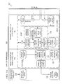
- FIG. 9 is a schematic of a merged graph 900 for the system S 1 as a result of Steps 504, 506 and 508 (of FIG. 5 ).
- This graph 900 shows all systems (e.g., S 2 904) and configurations (e.g., OCa 906 and ICz 908) that are directly or indirectly communicating with system S 1 902 via message flows.
- the next step links the message flows with the application and integration content 512.
- the reason for this step is that the result of the previous steps is a view on the network, but the discovered message flows only represent the communication between hosts and systems.
- outgoing call configurations may also have a link to application and integration content which is deployed and running on the systems.
- the link to a particular application proxy or to the system itself is determined. This is important because there might be a lot of applications running on one host at the same time.
- this step determines one or a set of outgoing call configurations. This is referred to as an integration process later.
- the final step is the incorporation of user enrichment 514.
- the quality of the Consolidated Model will improve over time as the algorithm gathers information from different data sources. Furthermore, it can learn from direct user input, also called "user enrichment.” These facts are marked by the postfix user to highlight the different origin compared to the discovered facts, which are indicated by the postfix_discx.
- URI Uniform Resource Identifier
- the incentive for knowledge validation is to prevent the knowledge base from becoming inconsistent due to different causes.
- users are allowed to inject facts as well. This is also a potential source of incorrect and inconsistent facts.
- customers or partners may build their own "fact providers", which extract facts from source systems and thus are possible causes of incorrect facts. Irrespective of the source of the facts stored in the knowledge base, they ought not cause the whole knowledge base to become inconsistent. For these reasons, the validation is crucial.
- the knowledge base is supposed to be consistent. Therefore, a validation before the persisting of the facts seems to be reasonable. The best point of time is during or after the inbound processing of the facts because if the validation is done right before the persisting process, the whole consolidation process has been finished. If there is one invalid fact, it is reasonable to detect it before the consolidation process starts.
- the Datalog facts may also be exported into the standard "fact providers" or the ones compiled by the partners or customers, another reasonable point of time is before the export of the facts. This ensures that only valid facts are exported.
- Deterministic Finite Automata may be used for fact validation.
- Technical systems may behave based on events. That is, they stay in a state until a specific event happens. Depending on their state and the event, they react with a specified action. Thus, the state is the "memory" of the system. Consequently, an event has two effects. On one hand, it causes the machine to noticeably react and on the other hand, it may lead to a change of the machine's internal state.
- Finite Automata are automata with a finite set of states. There are two kinds of finite automata: acceptors, which accept or decline an input, or transducers, which read an input and use it to generate an output.
- the set of all strings of a certain length k are expressed as ⁇ k .
- the set of strings with the length 2 ⁇ aa, ab, ac, ..., zz ⁇ .
- the set of all strings chosen from some ⁇ * for a particular alphabet ⁇ is also called language.
- L is the language over ⁇ , if L ⁇ ⁇ *
- the only constraint of a language is that all alphabets are finite. Even though they may have an infinite number of strings, languages are restricted to only contain strings that are in one fixed, finite alphabet.
- the decision of whether a given string is a member of a given language is called a problem.
- fact validation the problem is to decide whether a fact is valid, i.e., whether it is a member of the language which only consists of valid facts.
- DFA Deterministic Finite Automaton
- NFA Nondeterministic Finite Automata
- a DFA has the following characteristics:
- DFA Q ⁇ ⁇ ⁇ ⁇ ⁇ q 0 ⁇ F .
- DFA Q ⁇ ⁇ ⁇ ⁇ ⁇ q 0 ⁇ F .
- One notation is the transition diagram, which is a graph that contains one node for each state in Q .
- node q there is an arch from node q to node p labeled a for each state q in Q and each input symbol a in ⁇ .
- Nodes that represent accepting states are marked by a double circle while all states that are not in F (and therefore are non-accepting states) are marked by a single circle.
- FIG. 10 is a schematic representation of a transition diagram 1000 of a Deterministic Finite Automaton (DFA).
- DFA Deterministic Finite Automaton
- the DFA has three states. Depending on the input, it uses the available transitions to either go to its accepting state or to the non-accepting state.
- an automaton can either be an acceptor or a transducer. Talking only about acceptors, the action of accepting is not determined by the state the acceptor automaton is in for a single input symbol, but rather for a list of input symbols, which is called a string. The issue is the determination of the state the automaton is in after processing the whole input string w.
- the extended transition function In order to determine the last state of an automaton, the extended transition function has to be defined. Unlike the transition, which determines the next state for a given state and a given input symbol, the extended transition function determines the last state for an input string.
- the extended transition function ⁇ of DFA can be defined by induction on the length of the input string.
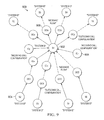
- FIG. 11 is a graph showing an excerpt 1100 of the dependencies of the facts. This graph shows an excerpt of the facts that depend on other facts. For example, for a system_discx fact 1104 to be valid there has to be a data_discx fact 1102 with the same key (e.g., URI ) . Another example is an operation_discx 1108, which depends on an incoming_discx 1110 and/or outgoing_discx 1112 with its configURI and on a valid data_discx with its operation URI .
- one fact depends on one of two facts, e.g., a message_flow_discx, whose sender URI and receiver URI depend on either a valid incoming_discx 1110 / outgoing_discx 1112 or a valid system_discx 1104.
- FIG. 11 shows, there are some "clusters" of facts that may be validated independently from others. For example, when validating a message_flow_discx 1114, the host_discx 1116 facts are not relevant. However, the system_discx 1104 facts are all relevant as the sender URI and receiver URI depend on either an incoming_discx 1110 / outgoing_discx or a system_discx 1104. If it depends on two configuration facts, these facts also depend on system_discx 1104 facts and so on. This issue is shown in FIG. 12 .
- FIG. 12 is an excerpt 1200 of example resolved dependencies of a message_flow_discx fact 1202.
- FIG. 12 shows facts that may be relevant for the validation of a rrcessage_flow_discx fact 1202 (where the arrow means "depends on”). It is possible that a fact depends on either one fact or another.
- a fact of level 2 1204 or higher does not necessarily depend on all lower-level facts.
- a set that is composed of operation_discx, binding_discx (as shown in FIG. 11 ), and message_flow_discx 1202, incoming_discx 1206, outgoing_discx 1208, system_discx (e.g., 1210), host_discx (e.g., as shown in FIG. 11 ) and data_discx (e.g., 1212) facts one possibility to distribute the facts is using the following subsets S i (the_discx of the fact predicates is omitted due for readability):
- S 1 , S 2 and S 3 can be validated independently from each other as long as all fact sets including only facts with the same predicate are duplicated before.
- the automaton used for fact validation can be described just like the finite automaton described above. It also has a set of states ( Q' ) , a set of input symbols ( ⁇ '), a transition function ( ⁇ '), a start state ( q 0 ' ) , and a set of accepting states ( F ').
- a grammar G is defined as a fourtuple ( V, ⁇ , P ; S ):
- NFA Nondeterministic Finite Automaton
- L NFA w
- L(NFA) is the set of strings w in ⁇ * such that the extended transition function ⁇ ( q 0 ;w ) contains at least one final state while the set of final states is not empty.
- the main difference between NFAs and DFAs is the type of value that the transition function ⁇ returns. While a DFA returns one state, a NFA returns a set of states. Furthermore, there does not have to be a transition out of each state, which means, the sequence of states may "die.” However, the extended transition function is similar to a DFA's except that the next states of one state are determined by following all arcs out of this state labeled with the last input symbol.
- NFA N ( Q N ; ⁇ ; ⁇ N ; q 0 ; F N ) .
- the main idea of subset construction is that the constructed states of the DFA are sets of states of the NFA. For example, the start state of D is the only state included in the set that represents the start state of N.
- the construction of the other components of D is done as follows:
- ⁇ -transition enables the ⁇ -NFA to go to the next state spontaneously, i.e., without any input.
- This possibility does not change the language accepted by the automaton, but it provides some "convenience" on the automata construction.
- an optional input symbol can be modeled this way.
- the ⁇ -closure needs to be introduced in order to define the extended transition function.
- the ⁇ -closure is defined by recursion:
- ⁇ (q, w) is the set of states reached along the path whose labels form w where ⁇ 's do not contribute to w.
- Construction of an ⁇ -NFA for Fact Validation may use the knowledge about DFAs, NFAs and ⁇ -NFAs, and it is possible to design an automaton that validates facts.
- the following inductive proof will construct an ⁇ -NFA, which is able to validate facts.
- Theorem There exists some ⁇ -NFA that validates facts.
- FIG. 13 is a graphical representation 1300 of two types of argument validations.
- argument validations There are two types of argument validations: the first type is a normal argument and the second type is an argument that depends on another fact. It is assumed that the basic input of the automaton is an argument to be validated.
- the automaton goes from a first state 1302 to the next state 1304 if and only if the argument is valid.
- an argument depending on other facts is valid if and only if the lower-level fact is valid. If it is invalid, the argument is also invalid. Therefore, the lower-level fact has to be validated in the transition function.
- This fact validation is shown by the dotted edge in FIG. 13 transitioning from state 1308 to 1310 for a valid fact. The reason for the edge being dotted is that there may be more than one initial and one final state in this automaton.
- FIG. 14 is a graphical representation 1400 of a fact validation. There is one argument validation for each argument of the fact.
- FIG. 15 is a graphical representation 1500 of a completely constructed Epsilon-NFA for validating facts.
- This figure shows the embedding of the validation of a fact box 1502 into the validation of list of arguments box 1504.
- Validation of fact box 1502 includes two states 1506 and 1508.
- the dotted line is to signify the possibility of more than one initial and one final state.
- the automaton uses the ⁇ -transition to go back to the state 1510 in order to validate the next argument.
- FIG. 16 is a graphical representation 1600 of fact validation ⁇ -NFA used for subset construction. This is the same automaton as in FIG. 14 , but its states are named alphabetically in order to uniquely identify them
- the first state of the corresponding DFA is the set of states that includes the start state of the ⁇ -NFA and all states which can be reached by ⁇ -transitions from this state on. Therefore, the set of start states of the DFA includes the states a 1602 and b 1604. If the input is a valid argument, the ⁇ -NFA goes from state b 1604 to state c 1606. From c 1606, the states b 1604 and d 1608 can be reached by ⁇ -transitions. Therefore, the next state of the DFA includes the states b 1604, c 1606, and d 1608. From this state, the automaton goes to the same state on the input of any other valid argument. If there have been only valid arguments, at the end of the validation, the ⁇ -NFA goes to its accepting state using the last ⁇ -transition. Therefore, the state ⁇ b, c, d ⁇ of the DFA is an accepting state.
- the ⁇ -NFA goes to state b using its ⁇ -transition. Then, it stays in this state because it can only go to state c if the input is a valid argument. Therefore, the corresponding DFA goes to state ⁇ b ⁇ , which is a non-accepting state. It stays in this state, no matter whether the following argument is valid or not. If all previous arguments have been valid but the next argument is not, the ⁇ -NFA stays in state b. Therefore, the DFA again goes from ⁇ a, b ⁇ 1706 to state ⁇ b ⁇ 1704. Thus, the fact becomes invalid on the input of an invalid argument, no matter whether it is the first argument or any other.
- the constructed DFA is shown in FIG. 17. FIG.
- 17 is a graphical representation 1700 of a fact validation DFA created by subset construction.
- the automaton finishes the fact validation either in ⁇ b, c, d ⁇ 1702, if the fact consists of only valid arguments, or in ⁇ b ⁇ 1704, if there is at least one argument invalid.
- the Extended Transition Function After constructing a DFA out of an ⁇ -NFA, the question is whether both automata are equivalent in terms of fact validation.
- the Validation DFA accepts facts with at least one argument, just as the ⁇ -NFA.
- the success of the fact validation of both automata is represented by the state they finish their validation in. However, which state is this last state for a given argument?
- the extended transition function has to be used.
- the Validation DFA processes Datalog facts.
- the extended transition function ⁇ is defined similarly by using a fact instead of a string and an argument instead of a symbol:
- a is representing the start state of the ⁇ -NFA.
- f consists of at least one argument a i and that this argument can be either valid (which is denoted as a valid ) or invalid ( a invalid )
- the equivalence of the automata is shown by induction on the amount of arguments.
- Implementation of the automaton includes a structural and an object-oriented approach.
- the states of an automaton are implemented as integer variables.
- a variable is used to save the actual state.
- the actual state is looked up first and depending on it, the validation is done.
- the actual state is saved in the actualState variable.
- the transition function is implemented.
- the states can be reused in order to reduce maintenance effort and improve readability.
- One way of solving these problems is the encapsulation of the transitions into the states which is the main idea of the object-oriented approach.
- the states may have the same common interface as the automaton for the validation. Therefore, when an argument is supposed to be validated, the automaton delegates the validation to the actual state.
- the Context is the FVA and the Concrete States are all states needed to model the validation.
- the transition function of each state returns the next state that the automaton should go to. However, the automaton has the control to go to the next state, which may or may not be state "suggested" by the actual state.
- the main advantages of the implementation of the design pattern are the improved maintainability and reusability. Especially for facts of the model of dependencies that have a plurality of arguments with similar characteristics (e.g. , their optionality), one state implementation can be reused for all arguments with the same characteristics, no matter to which fact they belong.
- the maintainability and reusability of the object-oriented approach outperform the structural approach, the object-oriented approach is takes as a basis from now on. As a result, the transition functions are attached to the specific state.
- the automaton is not only able to validate one fact type (i.e ., facts with the same predicate), it is rather able to validate many facts with different predicates.
- each argument has a cardinality which tells whether the argument is optional or required. Therefore, the transition function of one state has to skip the validation of the argument. However, if the argument is required, it has to be validated.
- transition 4 is more complex as it includes the call of another FVA.
- the transition function and its states are implemented in Java. Therefore, it is not only possible to use all kinds of Java constructs, such as variable declarations, conditions and loops, but also calls of other FVA, RFCs or access to SAP systems. This and the fact of Java being a context-free language results in the automaton having a context-free character. However, it is still a DFA accepting regular languages as the number of Java constructs to be used is limited to variable declarations, conditions and finite loops in order to ensure the termination of the validation. Other constructs should not be used as they may not terminate. For example, an RFC may freeze on the remote location.
- FIG. 18 is a graphical illustration of a semantic model 1800. This class diagram shows the semantic model 1800.
- a fact model consists of a number of argument models.
- a semantic model is a subset of a domain model, which is the consolidated model described above. More precisely, the semantic model is an EDB (i.e., External Database) representation of the consolidated model.
- EDB External Database
- the fact model contains information about the predicate and the arity of the fact.
- the list of argument models is composed of argument models, which are identified by a name. The cardinality tells whether the argument is optional (which is represented by the value 0) or required (1).
- the isRef variable tells whether the argument depends on other facts, which are included in the set of references (refSet).
- each fact model has a key value which specifies the argument that uniquely identifies the fact.
- each fact has a list of states (stateList), which the FVA goes through.
- DSL domain-specific language
- a DSL is a computer program language of limited expressiveness focused on a particular domain.
- an external DSL is separate from the language of the main program.
- External DSL can have a custom syntax or be any other language (often XML). In this case, a custom language was defined.
- a definition file has to be written in the DSL to describe the semantic model. The process of creating, modifying and using the definition file is described above.
- the validation automaton is not only able to validate one fact; it is also able to validate a set of facts.
- a normal user rather needs the validation of a set of facts than the validation of a single fact as the main reason for the need of the fact validation is the dependencies of the facts.
- the validation of a single fact is mostly used by the automaton itself. Therefore, the validation process is defined as the process in which the validation automaton validates a given set of facts.
- the creation of the semantic model is needed by many components of the validation framework. Therefore, when the validation framework is started, the definition file is parsed and the semantic model is created.
- the fact models do not only include information about the arguments, they also include the state list that the automaton will need in order to validate the particular fact.
- the creation of the state list is shown in Algorithm 1, which needs the corresponding fact model as an input in order to resolve the dependencies of the fact.
- Algorithm 1 is an example algorithm for determining the state list for a fact.
- the first step is to check whether the argument is optional (see line 2). In this case, the validation of the argument needs to be skipped. If the argument is required, the next step is to check whether the argument refers to other fact models (see line 5). If there are no references to other facts, the algorithm searches for a fact- and argument-specific state, which has a specific naming. If there is such a state, the algorithm will take it (line 7). Otherwise, it will use the default state for argument validation (line 9). However, if there are dependencies to lower-level facts, a state for fact validation is added (line 12). At the end, the previously determined and the accepting state are added to the state list (lines 15 and 17) and the state list is returned (line 18).
- a fact set includes a number of facts that may or may not have the same predicate. If the facts do not have the same predicate, they may depend on each other.
- the set of facts, that will be validated later on, is a subset of the context or the context itself: ValidationFactorSet ⁇ Context
- C R ⁇ S ⁇ H ⁇ D S ⁇ D H
- the fact set S 1 will be valid as well, as for the system fact, there is a corresponding data fact in the context.
- S 2 R ⁇ I where I is an incoming configuration fact.
- the fact set S 2 will not be valid even though the arguments of all facts will be valid because there is no data fact DI that matches the config URI of the incoming configuration.
- the fact set S 3 will be valid as there are the corresponding lower-level facts in the fact set itself. Therefore, the automaton is not only able to validate a set of facts in the context, it is also able to validate the whole context.
- the first possible approach is the Random Approach, where the facts are validated as they are taken out of the set of facts to be validated.
- the computation of the level is a recursive function applied on a fact model (see Algorithm 2).
- Algorithm 2 is an example algorithm for determining the level of a fact model.
- the default level is 0 (line 1).
- 1 is added (line 9).
- the sum is compared to the highest level found until now. If the sum is higher than the highest level found, it is taken as the new level (line 11).
- the calculated level is returned (line 18).
- the calculated level can be used for two different validation approaches. The higher-level facts can be validated first. This is called Top-down Approach.
- a higher-level fact When a higher-level fact is validated, the fact it depends on is validated during the validation of the dependent fact. For example, during the validation of a system fact, there has to be a check whether a corresponding data fact exists. During this test, an automaton which validates the data fact is called. It validates the corresponding data fact and, if it is valid, returns the next state to the parent (system) automaton. Therefore, most of the lower-level facts are validated during the validation of higher-level facts. In contrast to that, there is the Bottom-up Approach where the lower-level facts are validated first. Therefore, when the higher-level facts are validated, the facts that they depend on do not have to be validated again. They will be skipped.
- FIG. 19 is a schematic representation of an example implementation 1900 a shared memory 1902.
- each FVA e.g., FVA1 1904
- These spots can also be used by more than one automaton.
- the implemented shared memory facilitates the storage of all facts that have already been validated. Consequently, each FVA needs the ID of the part of the shared memory 1902 it is supposed to use. This enables it to put all valid facts into this part of the shared memory 1902.
- the automaton can skip this validation.
- any time a sub-automaton is called it gets the ID of a shared memory 1902 section as an input. As a result, it also puts all valid facts into the same part of the shared memory 1902 that the parent automaton uses. This facilitates a fact validation distributed between different automata. Furthermore, each automaton has a local memory 1906 where it puts all facts that have not been successfully validated. As a result, when it is supposed to validate the invalid fact again, the automaton can skip the validation because it already "knows" that this fact is invalid.
- the automaton can start to validate a set of facts. As mentioned above, it does that using a given approach.
- the approach determines the order for the validation and the automaton will validate one fact after another in the order that the approach defines. However, before the actual validation can start, there has to be done some preprocessing (see Algorithm 3), which checks whether all conditions, needed to validate the fact, are fulfilled.
- Algorithm 3 is an example algorithm for preprocessing for fact validation.
- the automaton checks whether the validation of the actual fact can be skipped because it is contained in the shared memory and thus has been validated before (line 2). If this is not the case, the automaton makes sure that:
- Algorithm 4 is an example algorithm for determining a next state for the automaton.
- the state S j I + 1, whose index is one higher than the index of the actual argument, is returned (line 3).
- an error state is returned (line 5).
- Algorithm 5 is an example algorithm for validation of a fact. For each argument of the fact, the transition function of the actual state is called (line 3). It will return a state depending on the validation success. If this return state is the same state that the automaton is in at the moment, the validation of the argument was not successful. Then, the loop over the argument is stopped because if one argument is invalid, the fact cannot become valid any more (line 5). Otherwise, the actual state is set to the state returned by the actual state (line 7).
- Algorithm 6 is an example algorithm for fact validation post-processing. If the actual state of the automaton is its accepting state, the validation of the fact was successful. If so, and if the valid fact is the first fact that has been validated, the successful variable is set to be true (line 3). Note that this is only done for the first fact because the default value of the successful variable is false. The reason for this is that if no fact has been validated yet, the validation cannot be successful. Furthermore, the fact is added to the shared memory containing all valid facts if and only if the validation was successful (line 5). However, if the fact is invalid, the successful variable is set to be false (line 7) and the fact is added to the local set of invalid facts (line 8).
- Algorithm 7 is an example algorithm for a fact validation transition function.
- the context for the local FVA is defined as the set union of the fact set that the parent FVA validates, the context of the parent FVA and the shared memory that contains all facts that have already been validated by the parent FVA (line 1).
- the parent FVA is the automaton whose transition function calls another automaton (in this case the local FVA).
- all lower-level facts that the actual argument depends on are determined (line 2), which is shown in Algorithm 8.
- Algorithm 8 is an example algorithm for determining dependency facts of an argument. After the determination of the actual argument model (line 1), for all fact models that the argument model depends on, all facts in the context with the same predicate are added to the set of prospect dependency facts (line 3). This means, that all facts that the actual fact may depend on are to be validated later on (Algorithm 7, line 3).
- a local FVA is called to perform the validation (line 7). If the validation was successful, the fact is added to the shared memory and the next state is added to the return state set (lines 9 and 10). However, if the lower-level fact is not valid, it is added to the invalid fact set of the local FVA and the actual fact is added to the invalid fact set of the parent FVA (line 12). Furthermore, the actual state is added to the set of prospect return states (line 13). At the end, the return state out of the set of prospect return states is determined (line 17). This is shown in Algorithm 9.
- Algorithm 9 is an example algorithm for determining a return state for a fact validation transition function. If the set of return states contains only one state, this state is returned (line 2). If there are more states in the set of prospect return states, an error state is returned if there is one in the set (line 4) because if this happens, an error has occurred during the validation of the local FVA. However, if the set contains the actual state, it is returned (line 6) as this means that the lower-level fact is not valid. If none of the cases mentioned occur, any state is returned (line 8). Then, the parent FVA can continue with its validation process.
- FIG. 20 is a graphical representation of an example programming model 2000 for the automaton 2002.
- the automaton 2002 gets the facts 2008 and the definition file 2006 as inputs.
- a semantic model 2004 is built using the definition file 2006. Using this model, the automaton 2002 is able to validate a set of facts.
- the output is realized as a textual log 2010 and a dot graph 2012.
- the definition file is used to create the semantic model. It is used by the automaton that validates the given facts. At the end of the validation, there is some output which can be used to diagnose the result of the validation.
- the definition file written in an external domain-specific language, is used to create the semantic model. Therefore, the model has to be described in the definition file at design time.
- the language that the definition file is written is defined by the following grammar: ⁇ fact predicate> [ ⁇ key index> ]: ⁇ argument list>.
- the key index is the integer value that indicates the index of the argument in the argument list that uniquely identifies the fact. Therefore, in most cases, this will be a URI.
- the key index is an optional value as there are facts that do not have a single key argument, for example the runs_on fact, which can only be uniquely identified by both arguments, the system URI and the host URI .
- Listing 1 is an example excerpt from a definition file.
- Listing 1 shows the definition of the data_discx and the system_discx facts, as well as two comments.
- the data_discx fact is defined.
- Its key argument is the URI, the other three arguments are optional.
- none of the arguments depend on other facts.
- there is another comment which is followed by the definition of the system_discx fact in the last line.
- the name of this fact is not optional as the cardinality is 1 while the description is optional.
- the last argument which is the system URI at index 2 of the argument list, is a required argument which depends on a valid and matching data_discx fact.
- a state is a Java class that is named using the following schema: Validate ⁇ fact predicate> ⁇ argument name> The name starts with the literal "Validate" followed by the fact predicate and the name of the argument that this state is for.
- the name for a state that validates system names should be ValidateSystem_discxName It is very important that the fact predicate and the argument name are the ones that were defined in the definition file. In the example above, the first letters of the fact predicate and argument name are in capitalized. The reason for that is a better readability. However, the validation framework will also recognize lowercase predicates and names.
- the validation programs can be logged and used for debugging purposes (in certain embodiments, in realtime).
- the result of the validation is either successful or not.
- the automaton facilitates logging of what it does.
- the following events can be logged:
- the automaton calls its logger, which is the implementation of a Visitor design pattern and logs the event.
- the logger has a reference to the automaton, it can access all the information needed to produce a useful log in the way the user wants the output.
- the textual output is a description of what the automaton does at the moment, i.e., which part of the validation it has just finished. For example, when an automaton validates one data fact, the output would look like the output shown in Listing 2.
- Listing 2 is an example textual output of the automaton for a valid data fact.
- the logger logs the start of the automaton, the start of the validation of the data fact, the validation of the arguments and the end of the fact and the automaton. It also logs whether the validation of one fact and all facts was successful or not.
- the logger logs the start of the automaton and how many facts are in the fact set to be validated. Then it logs the start of the validation of the data fact. Next, it logs the validation of the arguments and their success. After this, it logs the end of the validation of the data fact and whether it is valid or not. After all facts are validated, it logs the end of the automaton and the status of the overall validation, i.e., whether all facts are valid or not.
- the second way of logging is the graphical output, which is implemented using dot graphs.
- dot is used to "draw directed graphs as hierarchies.” Therefore, it reads text files, which contain the description of the graph in a specific format, and creates drawings in different graphics formats.
- Listing 3 shows a text file which contains the description of a dot graph for a valid data fact.
- Listing 3 is an example description of a dot graph for a valid data fact.
- Listing 3 includes the states and the transitions of an FVA described in dot.
- the digraph G in line 1 means that the graph G is supposed to be a directed graph.
- the braces are used to mark which parts of the graph belong together just like in any programming language.
- the rankdir LR; anticipates that the graphs are drawn from left to right.
- the semicolon is used to end an instruction, which is also similar to some programming languages (e.g., Java).
- the entity is not labeled with its unique name, but rather with the specified label.
- the label does not have to be unique.
- the label of the subgraph is defined in line 4.
- the node's unique name has to be written into the subgraph's body.
- nodes can also be labeled.
- Listing 3 there are five nodes assigned to the subgraph. For logging, each node represents one state that the automaton was in. Edges represent the transitions of the automaton. In the textual description of the dot graph, the edges are defined at the end of the main graph.
- the first node has to be written down at the beginning of the line, followed by an arrow ( ⁇ ).
- the directed edge goes to, followed by the semicolon to end the command.
- the edge between the first and the second state of the automaton is defined in line 11. After validation the argument of the data fact, the automaton goes to the next state (SkipArgumentValidation), therefore these two states were connected by an arrow.
- FIG. 21 is a graphical output 2100 for an example data fact.
- the automaton first has to validate the data URI and then skip the validation of three optional arguments. If no errors occur during these validations, the final state is denoted with an overlapping square.
- the label of the subgraph for the data fact in line 3 of the textual description of the dot graph (Listing 3) is the label at the top of the graph. It contains the fact that has been validated.
- the states the automaton went through during the validation are represented by the nodes of the dot graph.
- This state was logged by the logger after the automaton has finished the validation of the URI.
- the next three arguments of the automaton are optional, therefore the validation can be skipped. After skipping the validation of an argument, the corresponding state is logged.
- the automaton As soon as the automaton has finished the validation of a fact, it calls the logger which logs this event.
- the graphical logger analyzes whether the automaton has validated the fact successfully. If so, the final state denoted with an overlapping square. If the state the automaton is in after validating a fact is not its accepting state, the state is denoted with an overlapping triangle. Therefore it is convenient to use the dot graph to determine whether the validation was successful. If the fact to be validated is a fact whose level is higher than zero, there may be a call of an automaton in the transition function that validates the argument that is the key of another fact. In this case, the "path" the automaton went is shown with a solid arrow.
- the path the automaton would have gone if there was no call of another automaton is presented with a dotted arrow.
- the dot graph also shows which automaton was called. If the valid lower-level fact is supposed to be validated again, the automaton will skip the validation and the dot graph will show an automaton that has only one state: the accepting state (AllArguments Validated ) .
- the automaton logs whenever it validates a set of facts, a single fact or an argument.
- the validation automaton has two different possibilities to log what is does: one way of logging is textual by writing a short description what it is doing at the moment, another one is graphical by outputting a dot graph.
- both outputs can be combined in order to find the issues with the facts to be validated. To create a useful graphical output, in all cases, the top-down approach was used.
- Listing 4 is an example definition file for a runs_on fact with an invalid system fact.
- the user then starts the validation of the file.
- the automaton has logged the dot graph displayed in FIG. 21 .
- the user looks at the textual output for this validation (see Listing 5).
- Listing 5 is an example textual output of an automaton for a runs_on fact with an invalid system fact.
- the automaton realized that the name of the system is invalid, thus the fact is invalid. Consequently, the runs_on fact is invalid as well.
- the reason for the failure of the validation is the name of the system, which exceeds the allowed length.
- Listing 6 is an example definition file for a runs_on fact with a corresponding system fact and no data fact.
- the graphical output of the validation of this definition file is shown in FIG. 22 .
- FIG. 22 is a graphical output 2200 of an example automaton for a runs_on fact 2202 whose corresponding system fact 2204 has no corresponding data fact.
- the automaton validating the system fact 2204 was not able to find a matching data fact even though there is a valid data fact 2206.
- this data fact's URI differs from the system URI, thus the validation is not successful.
- the automaton started with the validation of the runs_on fact 2202. During this validation, it called another automaton responsible for the validation of the corresponding system fact.
- This automaton successfully passes the state which validates the system name, thus the fix of the system name was successful. However, this time, the automaton was not able to find a data fact with the same URI as the system fact 2204, which is displayed by the automaton being stuck in the ValidateFact state 2208.
- Listing 7 is an example textual output of the automaton for a runs_on fact with an invalid system fact.
- the problem is that the corresponding system fact has no matching data fact. There is only one data fact, but it has a different URI than the system as the last characters of the URIs differ.
- One pertinent part of the textual output is the following one (line 6 in Listing 7): system_discx : Can not find a valid data_discx with the same key systemURI : com .sap .bnm .nd. discovery .ale . facts . internal . AleFactsProviderHXPCLNT001 ). It shows that the automaton was not able to find a data fact with the same URI. This is the reason for the failure of the validation.
- FIG. 23 is a graphical output 2300 of an example automaton for a runs_on fact 2302 whose host URI is not specified. After successfully validating the system fact 2304 that matches the system URI of the runs_on fact 2302, the automaton was not able to validate the host URI , which was actually not specified. Therefore, the automaton stays in the (non-final) state ValidateFact. Following the directed edges in the graph, the automaton started the validation of the runs_on fact 2302. Next, it called another automaton to validate the system fact and its corresponding data fact. As these validations were successful, the control returned to the main automaton, which finally tried to validate the hostURI. Apparently, the automaton is stuck in this state. Maybe the textual output tells what the problem was with the host URI . The complete output is shown in Listing 8.
- Listing 8 is an example textual Output of the Automaton for an Invalid runs_on fact.
- the issue is that the host URI is not specified.
- the automaton was able to validate the matching system fact. When it tried to validate the host URI of the runs_on fact, it realized that it contains an empty string. Therefore, the validation failed.
- runs_on_discx No hostURI specified.
- the user changed his definition file by adding the host URI into the runs_on fact. When he does that, he realized that he did not create a host fact yet. To prevent himself from making the same mistake again, he also creates a host fact and its corresponding data fact.
- the definition file looks as shown in Listing 9.
- Listing 9 is an example definition file for a valid runs_on fact. There is a runs_on fact with a corresponding system and host fact that each has a matching data fact.
- FIG. 24 is a graphical output 2400 of an example automaton for a valid runs_on fact 2402.
- the validation of the runs_on 2402, system 2404, and data 2406 facts were all successful, thus all final states are denoted with overlapping squares.
- the final states of all automata are denoted with overlapping squares, which means that all facts are valid.
- Listing 10 is an example textual output of the automaton for a valid runs_on fact.
- the final message of the textual output (line 45 in Listing 10) is as follows: Validation Successful
- FIG. 25 is a schematic representation of an example system level system 2500 for content-based validation of knowledge.
- FIG. 25 illustrates an example trading environment system 2500.
- the system 2500 may include the marketplace management environment.
- the system 2500 may include a server 2504 coupled to one or more clients 2502, such a retailer, suppler, customer, bank, etc., at least some of which communicating across network 2530.
- Client 2502 includes an electronic computing device operable to receive, transmit, process, and store data associated with system 2500.
- FIG. 25 provides merely one example of computers that may be used with the disclosure, and, as such, each illustrated computer is generally intended to encompass any suitable processing device. For example, although FIG.
- the system 2500 can be implemented using computers other than servers, as well as a server pool.
- the system 2500 may be any computer or processing device such as, for example, a blade server, general-purpose personal computer (PC), Macintosh, workstation, Unix-based computer, or any other suitable device.
- PC general-purpose personal computer
- Macintosh workstation
- Unix-based computer Unix-based computer
- the present disclosure contemplates computers other than general purpose computers including computers without conventional operating systems.
- the system 2500 may be adapted to execute any operating system including Linux, UNIX, Windows Server, or any other suitable operating system.
- the system 2500 may also include or be communicably coupled with a web server and/or a mail server.
- the system 2500 may be communicably coupled with a remote repository 2506.
- the repository 2506 may include one or more persistent storage devices (e.g., hard drives, etc.) that form a storage backbone for the system 2500.
- the repository 2506 may include any intra-enterprise, inter-enterprise, regional, nationwide, or substantially national electronic storage facility, data processing center, or archive.
- the repository 2506 may include one or more hard disk drives, semiconductor memories, and the like that are coupled, either internally or externally, to the system 2500 via a direct connection, such as an integrated drive electronics (IDE) connection, a small computer systems interface (SCSI) connection, a Serial ATA (SATA) connection, or other suitable communicable connection.
- IDE integrated drive electronics
- SCSI small computer systems interface
- SATA Serial ATA
- the repository 2506 may be a central database communicably coupled to the system 2500 via a virtual private network (VPN), Secure Shell (SSH) tunnel, or other secure network connection.
- the repository 2506 may be physically or logically located at any appropriate location including in one of the example enterprises or off-shore, so long as it remains operable to store information associated with system 2500 and communicate such data to the system 2500.
- the repository 2506 may comprise a data store or warehouse.
- the repository 2506 allows for the system 2500 and/or one or more the trading participants to dynamically store and retrieve instructions 2505 or facts 2507 from the repository 2506.
- the instructions 2505 may include code that when executed by the system 2500 generate validation programs from semantic models 2512.
- the instructions 2505 may include code that is web-executable (e.g., java code) over the network 2530.
- client system 2502 may execute code from the instructions 2505 over the network 2530.
- Facts 2507 may be generated that may be subjected to validation.
- Repository 2506 may be a cloud based memory. It may be a distributed memory accessed across network 2530.
- Repository 2506 may be a shared memory, like that shown in FIG. 19 .
- the instructions 2505 may include software, firmware, wired or programmed hardware, or any combination thereof as appropriate.
- the instructions 140 may be written or described in any appropriate computer language including C, C++, Java, J#, Visual Basic, assembler, Perl, any suitable version of 4GL, as well as others.
- the instructions 140 may be implemented as Enterprise Java Beans ("EJBs") or the design-time components may have the ability to generate run-time implementations into different platforms, such as J2EE (Java 2 Platform, Enterprise Edition), ABAP (Advanced Business Application Programming) objects, or Microsoft's .NET.
- J2EE Java 2 Platform, Enterprise Edition
- ABAP Advanced Business Application Programming
- Microsoft's .NET Microsoft's .NET
- a portion of instructions 2505 may create a web service that is remotely called (e.g., by the retailer system), while another portion of instructions 2505 may be an interface object bundled for processing at a client (e.g., one of the trading participants). In another example, the majority of the instructions may also reside - or their processing take place - on one of the trading participants. Moreover, the instructions 2505 may be a child or sub-module of another software module or enterprise application (not illustrated) without departing from the scope of this disclosure.
- the repository 2506 may store also store facts 2510.
- the facts 2510 may include any business, enterprise, application or other transaction data and metadata involving the trading participants.
- the facts 2510 may include purchase histories, purchase trend information, entries in the master catalog, business profiles, other business attributes, and/or the business ratings, as described above, as well as other suitable marketplace related data.
- the system 2500 may mine the repository 2506 for the information needed used identify matches (i.e., new potential relationships) between the trading participants.
- the system 2500 may also include a processor 2508.
- the processor 2508 executes instructions and manipulates data to perform the operations of the system 2500.
- the processor 2508 may be, for example, a central processing unit ("CPU"), a blade, an application specific integrated circuit (“ASIC"), a field-programmable gate array (“FPGA”), or other suitable logic device.
- FIG. 25 illustrates a single processor 2508 in system 2500, multiple processors may be used according to particular needs and reference to processor 2508 is meant to include multiple processors where applicable.
- the system 2500 also includes local memory 2511.
- the memory 2511 may include instructions 2512 and facts 2510, which may each be a subset of the instructions 2505 and the facts 2507. As those of ordinary skill in the art will appreciate, the instructions 2512 and facts 2510 may be copied over to the memory prior to being executed or manipulated by the processor 2508.
- the memory 2511 may include any memory or other computer readable storage module and may take the form of volatile or non-volatile memory including, without limitation, magnetic media, optical media, random access memory (“RAM”), read-only memory (“ROM”), removable media, or any other suitable local or remote memory component.
- the memory 2511 may be internally or externally coupled to the system 2500.
- the system 2500 may also include interface 2514 for communicating with other computer systems, such as the other trading participants, over the network 2530.
- the system 2500 receives data from internal or external senders through the interface 2514 for storage in the memory 2511, for storage in repository 2506, and/or for processing by processor 2508.
- the interface 2514 comprises logic encoded in software and/or hardware in a suitable combination and operable to communicate with network 2530. More specifically, the interface 2514 may comprise software supporting one or more communications protocols associated with the network 2530 or hardware operable to communicate physical signals.
- the network 2530 facilitates wireless or wireline communication between the system 2500 and any other local or remote computer, such as the trading participants.
- the network 2530 may be all or a portion of an enterprise or secured network.
- network 2530 may be a VPN merely between one or more of the trading participants across a wireline or wireless link.
- Such an example wireless link may be via 802.11a, 802.11b, 802.11g, 802.11n, 802.20, WiMax, and many others. While illustrated as a single or continuous network, network 2530 may be logically divided into various sub-nets or virtual networks without departing from the scope of this disclosure, so long as at least portion of network 2530 may facilitate communications between system 2500 and at least one of the trading participants.
- the network 2530 encompasses any internal or external network, networks, subnetwork, or combination thereof operable to facilitate communications between various computing components in system 2500.
- Network 2530 may communicate, for example, Internet Protocol ("IP”) packets, Frame Relay frames, Asynchronous Transfer Mode (“ATM”) cells, voice, video, data, and other suitable information between network addresses.
- IP Internet Protocol
- Network 2530 may include one or more local area networks (“LANs”), radio access networks (“RANs”), metropolitan area networks (“MANs”), wide area networks (“WANs”), all or a portion of the global computer network known as the Internet, and/or any other communication system or systems at one or more locations.
- network 2530 may be a secure network associated with the enterprise and certain local or remote clients.
- Client 2502 may include any computing device operable to connect or communicate with the system 2500 or the network 2530 using any communication link.
- each of the trading participants may include or execute at least a graphical user interface ("GUI") 2516 and comprise an electronic computing device operable to receive, transmit, process and store any appropriate data associated with system 2500.
- GUI graphical user interface
- each of the trading participants is described in terms of being used by one user. But this disclosure contemplates that many users may use one computer or that one user may use multiple computers. In certain situations, users may include owners, bookkeepers, as well as third party or outside accountants.
- the GUI 2516 comprises a graphical user interface operable to allow the user of client 2502 to interface with at least a portion of system 2500 for any suitable purpose, such as viewing application or other transaction data.
- GUI 2516 provides the particular user with an efficient and user-friendly presentation of data provided by or communicated within system 2500.
- the GUI 2516 may comprise a plurality of customizable frames or views having interactive fields, pull-down lists, and buttons operated by the user.
- the GUI 2516 is operable to display certain elements, such as graphical and/or textual outputs of the validation process.
- the GUI 2516 may also present a plurality of portals or dashboards.
- GUI 2516 may display a portal that allows users to view, create, and manage validation program modeling and validation debugging.
- GUI 2516 contemplates any graphical user interface, such as a generic web browser or touchscreen, which processes information in system 2500 and efficiently presents the results to the user.
- the GUI 2516 can accept data from the system 2500 or the trading participants via the web browser (e.g., Microsoft Internet Explorer or Netscape Navigator) and return the appropriate HTML or XML responses using network 2530.
- the web browser e.g., Microsoft Internet Explorer or Netscape Navigator
- FIG. 26 is a process flow chart 2600 for validating a fact.
- a fact for validation may be identified (2602).
- a semantic model representing the fact may be created (2604).
- a context associated with the fact can be identified (2606).
- a validation program can be generated from the semantic model, the semantic model in a domain specific language (2608). The validation program facilitating the generation of automaton at runtime from the semantic model validates the fact (2610).
- a graphical and/or textual log of the validation can be outputted (2612). The graphical and/or textual log can be used for real-time debugging (2614).
- a target model different from the consolidated model can be used.
- Another runtime / validation program incarnation can be used. That is, a SAT solver or other non-automaton based implementation can be used.
- automata may be non-embedded, such as chained automata.
- Different output methods may be used for the debugging process.
- Different ways of representing the validation program than external DSL are also contemplated, such as internal DSL and fluent API.
- the disclosure contemplates an individually owned semantical model. Accordingly, other embodiments are within the scope of the following claims.
Landscapes
- Engineering & Computer Science (AREA)
- Theoretical Computer Science (AREA)
- General Engineering & Computer Science (AREA)
- Computing Systems (AREA)
- Evolutionary Computation (AREA)
- Physics & Mathematics (AREA)
- Data Mining & Analysis (AREA)
- Computational Linguistics (AREA)
- General Physics & Mathematics (AREA)
- Mathematical Physics (AREA)
- Software Systems (AREA)
- Artificial Intelligence (AREA)
- Information Retrieval, Db Structures And Fs Structures Therefor (AREA)
- Stored Programmes (AREA)
Applications Claiming Priority (1)
| Application Number | Priority Date | Filing Date | Title |
|---|---|---|---|
| US13/315,041 US8805769B2 (en) | 2011-12-08 | 2011-12-08 | Information validation |
Publications (2)
| Publication Number | Publication Date |
|---|---|
| EP2613283A2 true EP2613283A2 (de) | 2013-07-10 |
| EP2613283A3 EP2613283A3 (de) | 2014-01-29 |
Family
ID=47562913
Family Applications (1)
| Application Number | Title | Priority Date | Filing Date |
|---|---|---|---|
| EP12008205.2A Ceased EP2613283A3 (de) | 2011-12-08 | 2012-12-07 | Informationsvalidierung |
Country Status (4)
| Country | Link |
|---|---|
| US (1) | US8805769B2 (de) |
| EP (1) | EP2613283A3 (de) |
| JP (1) | JP6067356B2 (de) |
| CN (1) | CN103218288B (de) |
Families Citing this family (28)
| Publication number | Priority date | Publication date | Assignee | Title |
|---|---|---|---|---|
| US9275333B2 (en) * | 2012-05-10 | 2016-03-01 | Eugene S. Santos | Augmented knowledge base and reasoning with uncertainties and/or incompleteness |
| US10332010B2 (en) | 2013-02-19 | 2019-06-25 | Business Objects Software Ltd. | System and method for automatically suggesting rules for data stored in a table |
| US10740396B2 (en) | 2013-05-24 | 2020-08-11 | Sap Se | Representing enterprise data in a knowledge graph |
| US9405793B2 (en) | 2013-06-12 | 2016-08-02 | Sap Se | Native language support for intra-and interlinked data collections using a mesh framework |
| US9158599B2 (en) | 2013-06-27 | 2015-10-13 | Sap Se | Programming framework for applications |
| US11093521B2 (en) | 2013-06-27 | 2021-08-17 | Sap Se | Just-in-time data quality assessment for best record creation |
| US9311429B2 (en) | 2013-07-23 | 2016-04-12 | Sap Se | Canonical data model for iterative effort reduction in business-to-business schema integration |
| US11330024B2 (en) | 2014-01-29 | 2022-05-10 | Ebay Inc. | Personalized content sharing platform |
| US11176475B1 (en) | 2014-03-11 | 2021-11-16 | Applied Underwriters, Inc. | Artificial intelligence system for training a classifier |
| US11809434B1 (en) | 2014-03-11 | 2023-11-07 | Applied Underwriters, Inc. | Semantic analysis system for ranking search results |
| US9971973B1 (en) | 2016-05-23 | 2018-05-15 | Applied Underwriters, Inc. | Artificial intelligence system for training a classifier |
| EP2963599A1 (de) * | 2014-06-30 | 2016-01-06 | Siemens Aktiengesellschaft | Verwaltung der Ausführung eines Fertigungsauftrags |
| US10564937B2 (en) | 2014-07-18 | 2020-02-18 | Sap Se | Relational logic integration |
| US9406040B2 (en) | 2014-08-13 | 2016-08-02 | Sap Se | Classification and modelling of exception types for integration middleware systems |
| US9652787B2 (en) * | 2014-09-29 | 2017-05-16 | Ebay Inc. | Generative grammar models for effective promotion and advertising |
| CN107113183B (zh) * | 2014-11-14 | 2021-08-10 | 比特诺比有限责任公司 | 大数据的受控共享的系统和方法 |
| US9483329B2 (en) | 2015-02-09 | 2016-11-01 | Sap Se | Categorizing and modeling integration adapters |
| US10419586B2 (en) | 2015-03-23 | 2019-09-17 | Sap Se | Data-centric integration modeling |
| US9823906B2 (en) | 2016-03-31 | 2017-11-21 | Sap Se | Complementary model-driven and textual development using enforced formatting constraints |
| CN107783758B (zh) * | 2016-08-25 | 2019-01-18 | 北京航空航天大学 | 一种智能合约工程方法 |
| CN107450922B (zh) * | 2017-07-27 | 2020-01-03 | 武汉斗鱼网络科技有限公司 | 安卓中弹幕事件自动注册的方法、存储介质、设备及系统 |
| US10747584B2 (en) | 2018-08-20 | 2020-08-18 | Sap Se | Security-aware partitioning of processes |
| CN110516697B (zh) * | 2019-07-15 | 2021-08-31 | 清华大学 | 基于证据图聚合与推理的声明验证方法及系统 |
| US11121905B2 (en) | 2019-08-15 | 2021-09-14 | Forcepoint Llc | Managing data schema differences by path deterministic finite automata |
| US11587189B2 (en) | 2019-11-27 | 2023-02-21 | International Business Machines Corporation | Formal verification of smart contracts |
| RU2726957C1 (ru) * | 2020-01-09 | 2020-07-20 | Министерство региональной безопасности Омской области | Комплекс систем автоматизации |
| DE102021209612A1 (de) * | 2021-09-01 | 2023-03-02 | Robert Bosch Gesellschaft mit beschränkter Haftung | Vorrichtung, Computer-implementiertes Verfahren und Computerprogramm zur automatischen Analyse von Daten |
| KR20230042986A (ko) * | 2021-09-23 | 2023-03-30 | 연세대학교 산학협력단 | 글루시코프 오토마타 생성과 하이브리드 매칭을 활용한 정규 표현식 엔진에 관한 오토마타 처리 장치 및 방법 |
Family Cites Families (8)
| Publication number | Priority date | Publication date | Assignee | Title |
|---|---|---|---|---|
| JP2003084987A (ja) * | 2001-09-11 | 2003-03-20 | Internatl Business Mach Corp <Ibm> | Xml文書の妥当性を検証するためのオートマトンの生成方法、xml文書の妥当性検証方法、xml文書の妥当性を検証するためのオートマトンの生成システム、xml文書の妥当性検証システムおよびプログラム |
| US7181386B2 (en) * | 2001-11-15 | 2007-02-20 | At&T Corp. | Systems and methods for generating weighted finite-state automata representing grammars |
| EP1331630A3 (de) * | 2002-01-07 | 2006-12-20 | AT&T Corp. | Systeme und Verfahren zur Erzeugung von gewichteten endlichen Automaten die Grammatiken darstellen |
| CN101116052A (zh) * | 2004-12-21 | 2008-01-30 | 米斯特科技有限公司 | 网络接口及防火墙设备 |
| CN1955991A (zh) * | 2005-10-25 | 2007-05-02 | 国际商业机器公司 | 在业务模型中集成模型语义和领域语义的方法和装置 |
| CN101266550B (zh) * | 2007-12-21 | 2011-02-16 | 北京大学 | 一种恶意代码检测方法 |
| US8543653B2 (en) * | 2010-11-11 | 2013-09-24 | Sap Ag | Systems and methods for business network management discovery and consolidation |
| US8655989B2 (en) * | 2011-10-14 | 2014-02-18 | Sap Ag | Business network access protocol for the business network |
-
2011
- 2011-12-08 US US13/315,041 patent/US8805769B2/en active Active
-
2012
- 2012-12-07 EP EP12008205.2A patent/EP2613283A3/de not_active Ceased
- 2012-12-07 JP JP2012268180A patent/JP6067356B2/ja active Active
- 2012-12-10 CN CN201210528222.1A patent/CN103218288B/zh active Active
Non-Patent Citations (1)
| Title |
|---|
| None |
Also Published As
| Publication number | Publication date |
|---|---|
| JP2013120605A (ja) | 2013-06-17 |
| JP6067356B2 (ja) | 2017-01-25 |
| CN103218288B (zh) | 2017-07-07 |
| US8805769B2 (en) | 2014-08-12 |
| CN103218288A (zh) | 2013-07-24 |
| EP2613283A3 (de) | 2014-01-29 |
| US20130151463A1 (en) | 2013-06-13 |
Similar Documents
| Publication | Publication Date | Title |
|---|---|---|
| US8805769B2 (en) | Information validation | |
| Buijs | Flexible evolutionary algorithms for mining structured process models | |
| US8090754B2 (en) | Managing relationships of heterogeneous objects | |
| US8015541B1 (en) | Business process technology for the enterprise | |
| Rozinat | Process mining: conformance and extension | |
| US9165087B2 (en) | Validity path node pattern for structure evaluation of time-dependent acyclic graphs | |
| Becker et al. | Business process compliance checking–applying and evaluating a generic pattern matching approach for conceptual models in the financial sector | |
| US20090150906A1 (en) | Automatic electronic discovery of heterogeneous objects for litigation | |
| Merle et al. | A precise metamodel for open cloud computing interface | |
| Van Der Straeten | Inconsistency management in model-driven engineering | |
| US20080162616A1 (en) | Skip relation pattern for graph structures | |
| US20080162207A1 (en) | Relation-based hierarchy evaluation of recursive nodes | |
| US20080162777A1 (en) | Graph abstraction pattern for generic graph evaluation | |
| Abushark et al. | Requirements specification via activity diagrams for agent-based systems | |
| US20090024552A1 (en) | Unified development guidelines | |
| Refsdal et al. | Security risk analysis of system changes exemplified within the oil and gas domain | |
| Nadarajan et al. | Translating a typical business process modelling language to a Web Services Ontology through lightweight mapping | |
| Parreiras et al. | Towards a marketplace of open source software data | |
| Buschle | Tool Support for Enterprise Architecture Analysis: with application in cyber security | |
| Dijkman | Feedback on differences between business processes | |
| Shafiq | Semantically Formalized Logging and Advanced Analytics for Enhanced Monitoring and Management of Large-scale Applications | |
| Kammerer | Enabling Personalized Business Process Modeling: The Clavii BPM Platform | |
| Serrano Suarez | Automated API discovery, composition, and orchestration with linked metadata | |
| Ritter et al. | A Data Quality Approach to Conformance Checks for Business Network Models | |
| Alodib | Creation, integrating and deployment of diagnoser for web services |
Legal Events
| Date | Code | Title | Description |
|---|---|---|---|
| PUAI | Public reference made under article 153(3) epc to a published international application that has entered the european phase |
Free format text: ORIGINAL CODE: 0009012 |
|
| AK | Designated contracting states |
Kind code of ref document: A2 Designated state(s): AL AT BE BG CH CY CZ DE DK EE ES FI FR GB GR HR HU IE IS IT LI LT LU LV MC MK MT NL NO PL PT RO RS SE SI SK SM TR |
|
| AX | Request for extension of the european patent |
Extension state: BA ME |
|
| PUAL | Search report despatched |
Free format text: ORIGINAL CODE: 0009013 |
|
| AK | Designated contracting states |
Kind code of ref document: A3 Designated state(s): AL AT BE BG CH CY CZ DE DK EE ES FI FR GB GR HR HU IE IS IT LI LT LU LV MC MK MT NL NO PL PT RO RS SE SI SK SM TR |
|
| AX | Request for extension of the european patent |
Extension state: BA ME |
|
| RIC1 | Information provided on ipc code assigned before grant |
Ipc: G06N 5/02 20060101AFI20131220BHEP |
|
| 17P | Request for examination filed |
Effective date: 20140724 |
|
| RBV | Designated contracting states (corrected) |
Designated state(s): AL AT BE BG CH CY CZ DE DK EE ES FI FR GB GR HR HU IE IS IT LI LT LU LV MC MK MT NL NO PL PT RO RS SE SI SK SM TR |
|
| RAP1 | Party data changed (applicant data changed or rights of an application transferred) |
Owner name: SAP SE |
|
| 17Q | First examination report despatched |
Effective date: 20150225 |
|
| STAA | Information on the status of an ep patent application or granted ep patent |
Free format text: STATUS: THE APPLICATION HAS BEEN REFUSED |
|
| 18R | Application refused |
Effective date: 20161004 |