EP2613045A1 - Supply system for supplying an internal combustion engine with air and fuel - Google Patents
Supply system for supplying an internal combustion engine with air and fuel Download PDFInfo
- Publication number
- EP2613045A1 EP2613045A1 EP13150712.1A EP13150712A EP2613045A1 EP 2613045 A1 EP2613045 A1 EP 2613045A1 EP 13150712 A EP13150712 A EP 13150712A EP 2613045 A1 EP2613045 A1 EP 2613045A1
- Authority
- EP
- European Patent Office
- Prior art keywords
- fuel
- valve
- intake conduit
- supply circuit
- flow rate
- Prior art date
- Legal status (The legal status is an assumption and is not a legal conclusion. Google has not performed a legal analysis and makes no representation as to the accuracy of the status listed.)
- Withdrawn
Links
- 239000000446 fuel Substances 0.000 title claims abstract description 43
- 238000002485 combustion reaction Methods 0.000 title claims abstract description 17
- 230000009347 mechanical transmission Effects 0.000 claims abstract description 7
- 238000003745 diagnosis Methods 0.000 claims description 2
- 230000003213 activating effect Effects 0.000 claims 1
- 230000004913 activation Effects 0.000 claims 1
- 238000002347 injection Methods 0.000 description 12
- 239000007924 injection Substances 0.000 description 12
- 230000005540 biological transmission Effects 0.000 description 7
- 230000008901 benefit Effects 0.000 description 2
- 238000011144 upstream manufacturing Methods 0.000 description 2
- 230000008859 change Effects 0.000 description 1
- 238000010276 construction Methods 0.000 description 1
- 230000008878 coupling Effects 0.000 description 1
- 238000010168 coupling process Methods 0.000 description 1
- 238000005859 coupling reaction Methods 0.000 description 1
- 238000010586 diagram Methods 0.000 description 1
- 239000003344 environmental pollutant Substances 0.000 description 1
- 239000012530 fluid Substances 0.000 description 1
- 239000002828 fuel tank Substances 0.000 description 1
- 239000000203 mixture Substances 0.000 description 1
- 230000004048 modification Effects 0.000 description 1
- 238000012986 modification Methods 0.000 description 1
- 231100000719 pollutant Toxicity 0.000 description 1
- 238000010298 pulverizing process Methods 0.000 description 1
- 230000004044 response Effects 0.000 description 1
Images


Classifications
-
- F—MECHANICAL ENGINEERING; LIGHTING; HEATING; WEAPONS; BLASTING
- F02—COMBUSTION ENGINES; HOT-GAS OR COMBUSTION-PRODUCT ENGINE PLANTS
- F02D—CONTROLLING COMBUSTION ENGINES
- F02D41/00—Electrical control of supply of combustible mixture or its constituents
- F02D41/30—Controlling fuel injection
-
- F—MECHANICAL ENGINEERING; LIGHTING; HEATING; WEAPONS; BLASTING
- F02—COMBUSTION ENGINES; HOT-GAS OR COMBUSTION-PRODUCT ENGINE PLANTS
- F02M—SUPPLYING COMBUSTION ENGINES IN GENERAL WITH COMBUSTIBLE MIXTURES OR CONSTITUENTS THEREOF
- F02M71/00—Combinations of carburettors and low-pressure fuel-injection apparatus
-
- F—MECHANICAL ENGINEERING; LIGHTING; HEATING; WEAPONS; BLASTING
- F02—COMBUSTION ENGINES; HOT-GAS OR COMBUSTION-PRODUCT ENGINE PLANTS
- F02D—CONTROLLING COMBUSTION ENGINES
- F02D41/00—Electrical control of supply of combustible mixture or its constituents
- F02D41/22—Safety or indicating devices for abnormal conditions
-
- F—MECHANICAL ENGINEERING; LIGHTING; HEATING; WEAPONS; BLASTING
- F02—COMBUSTION ENGINES; HOT-GAS OR COMBUSTION-PRODUCT ENGINE PLANTS
- F02M—SUPPLYING COMBUSTION ENGINES IN GENERAL WITH COMBUSTIBLE MIXTURES OR CONSTITUENTS THEREOF
- F02M17/00—Carburettors having pertinent characteristics not provided for in, or of interest apart from, the apparatus of preceding main groups F02M1/00 - F02M15/00
- F02M17/14—Carburettors with fuel-supply parts opened and closed in synchronism with engine stroke ; Valve carburettors
- F02M17/147—Valve carburettor with simultaneous air and fuel control
Definitions
- the present invention relates to a supply system for supplying an internal combustion engine with air and fuel.
- the fuel is injected into the cylinders (direct injection), or in a combustion air intake conduit (indirect injection), by way of injectors having electromagnets, or other types of electric actuators, which are controlled by an electronic unit as a function of the flow rate of intake combustion air to set the injection timing.
- the electronic unit communicates with other engine devices and receives signals from measuring sensors (lambda sensor, mass flow sensor, throttle valve position sensor, temperature and pressure sensors, etc. ...) related to the engine operating parameters.
- the purpose of the present invention is to provide a supply system for supplying an internal combustion engine with air and fuel, which allows to satisfy in a simple and economic way the need set forth above.
- a supply system for supplying an internal combustion engine with air and fuel, as defined in claim 1.
- number 1 indicates a supply system (schematically shown) for supplying air and fuel into the cylinders 2 of an internal combustion engine 3 (schematically shown).
- the system 1 comprises: an intake conduit 5, which conveys combustion air from an external environment to the intake valves of the cylinders 2; and a throttle valve 10, for example a butterfly valve, of a type known per se, which is connected by way of a mechanical transmission 14 to a control member 11 (shown schematically), for example an accelerator pedal, which is operable by a user.
- the throttle valve 10 when operated, varies the flow passage in a portion 13 of the intake conduit 5 and, therefore, regulates the combustion air flow rate towards the engine 3.
- the portion 13 is normally referred to as "throttle housing".
- the transmission 14 is of the type with Bowden cable.
- an electric operation also commonly called “fly by wire” can be provided.
- the position of the movable element of the throttle valve 10 is detected by a position sensor 15, which emits a signal indicative of the restriction of the passage section. Said signal is received by an electronic unit 16, which determines, in a known way and not described in detail, the flow rate of combustion air conveyed to the engine 3 and controls one or more electro-injectors 17 by way of electrical signals to adjust the dosage of fuel entering the cylinders 2.
- a position sensor 15 which emits a signal indicative of the restriction of the passage section.
- Said signal is received by an electronic unit 16, which determines, in a known way and not described in detail, the flow rate of combustion air conveyed to the engine 3 and controls one or more electro-injectors 17 by way of electrical signals to adjust the dosage of fuel entering the cylinders 2.
- each cylinder 2 is provided with a respective electro-injector 17.
- a single electro-injector 17 can be provided which injects fuel into the intake conduit 5.
- the electro-injector 17 constitutes part of a supply circuit 18, which conveys fuel from a tank 19.
- the system 1 comprises a supply circuit 20, which is independent from the circuit 18, and is adapted to convey fuel in the intake conduit 5 due to a depression into the intake conduit 5 itself.
- the system 1 operates according to a first configuration wherein the circuit 18 of the "injection" type is active, for which the air/fuel mixture necessary for supplying the engine 3 is adjusted by way of the electronic unit 16.
- the nozzle 25 is isolated and does not receive fuel, for example because the circuit 20 is inhibited by a selector valve 22, which diverts the fuel from the tank 19 to the circuit 18.
- the system 1 can operate in a second configuration, wherein the circuit 20 is active, while the circuit 18 is isolated and does not receive fuel.
- the valve 22 is switched so as to divert the fuel from the tank 19 to the circuit 20 and isolate the circuit 18.
- other technical devices may be provided having the same function, for example appropriate shut-off valves adapted to change configuration of the system 1 and selectively activate one or the other of the circuits 20, 18.
- the circuit 20 is activated automatically in the event of an interruption of power supply.
- the valve 22 is a two-position monostable electro-valve, controlled by the control unit 16. In the absence of electrical signal from the control unit 16 (for example a power failure), the valve 22 is automatically switched as a result of its own elastic element 23, so as to supply fuel to the circuit 20.
- the circuit 20 can be forcibly manually activated by a user by way of a control member 24, which is mechanically connected to the valve 22, in order to directly intervene in case of failure.
- a real-time control by the control unit 16 can be provided, which comprises a diagnosis function of the system 1 and, in case of failure of the circuit 18, controls the closing of the circuit 18 and the opening of the circuit 20.
- the circuit 20 ends with a nozzle 25, which is arranged in the intake conduit 5 and has a function of atomizer, as it is provided with holes such as to atomize the flowing out fuel because of the depression in the intake conduit 5.
- the vacuum is generated by the fact that the portion 13 has a diffuser or Venturi shape and, preferably, the nozzle 25 is arranged in the portion 13 downstream of the throttle valve 10.
- the circuit 20 also comprises a pressure regulator 26 which is arranged between the valve 22 and the nozzle 25 and operates according to the pressure in the intake conduit 5.
- the fuel flow exiting from the circuit 20 is adjusted by the movable element of a valve 27.
- This movable element is operated by a mechanical transmission 28 in response to mechanical operation of the movable element of the throttle valve 10.
- the transmission 28 connects the throttle valve 10 to the movable element of the valve 27 and is arranged outside the intake conduit 5.
- the transmission 28 connects the control member 11 to the movable element of the valve 27 and acts together and in parallel to the transmission 14.
- the movable element of the valve 27 is of the sliding type.
- said movable element is defined by a needle 29, which is coaxial to the nozzle 25, is arranged in a position diametrically opposed to the nozzle 25 with respect to the axis of the intake conduit 5 and is connected in fluid tight manner to the portion 14 by way of a guide and slide coupling 30.
- the portion 14 comprises an outer projection 32, which performs the guiding function on the needle 29.
- the transmission 28 comprises an elastic element 33 which tends to open the nozzle 25 by exerting a thrust on the needle 29 outwards and is defined, in particular, by a helical spring fitted around the portion 32.
- the transmission 28 comprises, moreover, a cam 35 operated by the movable element of the throttle valve 10, and a tappet 36, which is pressed against the cam 35 and moves together with the needle 29.
- the cam 35 rotates together with the butterfly element of the throttle valve 10 about an axis 38 parallel to the translation axis of the needle 29, and is defined by a ramp which extends in the form of an arc of a circle around the axis 38 ( Fig. 3 ).
- the tappet 36 is maintained by the elastic element 33 against the ramp:
- Figure 2 shows the two end positions assumed by the tappet 36 due to the rotation of the ramp 35.
- Figure 4 shows some variants that may be provided in combination or alternatively to one another:
- system 1 is to use under normal conditions an "injection" supply system that ensures optimum performance with respect to efficiency, fuel consumption, emissions, etc..., but to be able to exploit a supply system similar to that of a carburetor when the "injection" supply system suffers failure.
- the combination of the two systems provides a redundancy that ensures the safety in case of application of the system 1 on an airplane, in the event of failures, without having a simple duplication of an "injection" supply system or a simple duplication of a carburetor supply system.
- the characteristics of the system 1 allows to limit constructive complications and consequently the costs of the system 1 itself, and are designed to switch the configuration to the circuit 20 in case of necessity in a simple and/or automatic way.
- the engine 3 continues to regularly operate, without causing inconvenience to the flight on the aircraft upon which it is installed.
- the pressure regulator 26 may be absent, and/or a fuel tank with floats can be provided.
- valves 10 and or 27 may be different from those described; and/or the transmission 28 could be different from that indicated by way of example, as a function of available spaces and/or as a function of the type of valves 10 and 27.
Landscapes
- Engineering & Computer Science (AREA)
- Chemical & Material Sciences (AREA)
- Combustion & Propulsion (AREA)
- Mechanical Engineering (AREA)
- General Engineering & Computer Science (AREA)
- Electrical Control Of Air Or Fuel Supplied To Internal-Combustion Engine (AREA)
- Fuel-Injection Apparatus (AREA)
Abstract
Description
- The present invention relates to a supply system for supplying an internal combustion engine with air and fuel.
- As known, in internal combustion engines of the injection type, the fuel is injected into the cylinders (direct injection), or in a combustion air intake conduit (indirect injection), by way of injectors having electromagnets, or other types of electric actuators, which are controlled by an electronic unit as a function of the flow rate of intake combustion air to set the injection timing. In particular, the electronic unit communicates with other engine devices and receives signals from measuring sensors (lambda sensor, mass flow sensor, throttle valve position sensor, temperature and pressure sensors, etc. ...) related to the engine operating parameters.
- Thanks to the precision in the determination of the amount of fuel and the pressure of the fuel injected (which causes a fine pulverization of the fuel itself), it is possible to obtain high performance and low fuel consumption and to limit the emissions of pollutants.
- When the electronic injection engines are applied on airplanes, in particular on ultralight aircraft, the need is felt to provide devices that allow the engine to operate properly even in the event of a failure of the injection system and/or a failure that causes an interruption in the electric supply to the injectors and fuel pumps.
- The purpose of the present invention is to provide a supply system for supplying an internal combustion engine with air and fuel, which allows to satisfy in a simple and economic way the need set forth above.
- According to the present invention, a supply system is provided for supplying an internal combustion engine with air and fuel, as defined in claim 1.
- The invention will now be described with reference to the accompanying drawings, which show a non-limiting embodiment, wherein:
-
Figure 1 is a block diagram of a preferred embodiment of the supply system for supplying an internal combustion engine with air and fuel, according to the present invention; -
Figure 2 shows, in cross section, a detail of the system ofFigure 1 ; -
Figure 3 is a bottom view of the detail ofFigure 2 ; and -
Figure 4 is similar toFigure 2 and shows, on an enlarged scale, a variant of a detail ofFigure 2 . - In
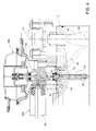
figure 1 , number 1 indicates a supply system (schematically shown) for supplying air and fuel into thecylinders 2 of an internal combustion engine 3 (schematically shown). - The system 1 comprises: an
intake conduit 5, which conveys combustion air from an external environment to the intake valves of thecylinders 2; and athrottle valve 10, for example a butterfly valve, of a type known per se, which is connected by way of amechanical transmission 14 to a control member 11 (shown schematically), for example an accelerator pedal, which is operable by a user. Thethrottle valve 10, when operated, varies the flow passage in aportion 13 of theintake conduit 5 and, therefore, regulates the combustion air flow rate towards the engine 3. In the case of a butterfly valve, theportion 13 is normally referred to as "throttle housing". Preferably, thetransmission 14 is of the type with Bowden cable. As an alternative to the mechanical transmission, an electric operation, also commonly called "fly by wire" can be provided. - The position of the movable element of the
throttle valve 10 is detected by aposition sensor 15, which emits a signal indicative of the restriction of the passage section. Said signal is received by anelectronic unit 16, which determines, in a known way and not described in detail, the flow rate of combustion air conveyed to the engine 3 and controls one or more electro-injectors 17 by way of electrical signals to adjust the dosage of fuel entering thecylinders 2. In the case of direct injection, eachcylinder 2 is provided with a respective electro-injector 17. In the case of indirect injection, a single electro-injector 17 can be provided which injects fuel into theintake conduit 5. - The electro-
injector 17 constitutes part of asupply circuit 18, which conveys fuel from atank 19. In parallel to thecircuit 18, the system 1 comprises asupply circuit 20, which is independent from thecircuit 18, and is adapted to convey fuel in theintake conduit 5 due to a depression into theintake conduit 5 itself. - In normal operating conditions, the system 1 operates according to a first configuration wherein the
circuit 18 of the "injection" type is active, for which the air/fuel mixture necessary for supplying the engine 3 is adjusted by way of theelectronic unit 16. In this configuration, thenozzle 25 is isolated and does not receive fuel, for example because thecircuit 20 is inhibited by aselector valve 22, which diverts the fuel from thetank 19 to thecircuit 18. - The system 1 can operate in a second configuration, wherein the
circuit 20 is active, while thecircuit 18 is isolated and does not receive fuel. To switch to the second configuration, thevalve 22 is switched so as to divert the fuel from thetank 19 to thecircuit 20 and isolate thecircuit 18. Alternatively to thevalve 22, other technical devices may be provided having the same function, for example appropriate shut-off valves adapted to change configuration of the system 1 and selectively activate one or the other of thecircuits - According to a preferred aspect of the invention, the
circuit 20 is activated automatically in the event of an interruption of power supply. In fact, in the example schematically illustrated, thevalve 22 is a two-position monostable electro-valve, controlled by thecontrol unit 16. In the absence of electrical signal from the control unit 16 (for example a power failure), thevalve 22 is automatically switched as a result of its ownelastic element 23, so as to supply fuel to thecircuit 20. - Alternatively or in combination with the automatic mechanical switching, the
circuit 20 can be forcibly manually activated by a user by way of acontrol member 24, which is mechanically connected to thevalve 22, in order to directly intervene in case of failure. - Furthermore, in combination or as an alternative to the above, to switch the system 1 in the second configuration a real-time control by the
control unit 16 can be provided, which comprises a diagnosis function of the system 1 and, in case of failure of thecircuit 18, controls the closing of thecircuit 18 and the opening of thecircuit 20. - With reference to
Figure 2 , thecircuit 20 ends with anozzle 25, which is arranged in theintake conduit 5 and has a function of atomizer, as it is provided with holes such as to atomize the flowing out fuel because of the depression in theintake conduit 5. The vacuum is generated by the fact that theportion 13 has a diffuser or Venturi shape and, preferably, thenozzle 25 is arranged in theportion 13 downstream of thethrottle valve 10. In the preferred embodiment shown inFigure 2 , thecircuit 20 also comprises apressure regulator 26 which is arranged between thevalve 22 and thenozzle 25 and operates according to the pressure in theintake conduit 5. - The fuel flow exiting from the
circuit 20 is adjusted by the movable element of avalve 27. This movable element is operated by amechanical transmission 28 in response to mechanical operation of the movable element of thethrottle valve 10. In particular, thetransmission 28 connects thethrottle valve 10 to the movable element of thevalve 27 and is arranged outside theintake conduit 5. Alternatively, thetransmission 28 connects thecontrol member 11 to the movable element of thevalve 27 and acts together and in parallel to thetransmission 14. - In particular, the movable element of the
valve 27 is of the sliding type. Conveniently, said movable element is defined by aneedle 29, which is coaxial to thenozzle 25, is arranged in a position diametrically opposed to thenozzle 25 with respect to the axis of theintake conduit 5 and is connected in fluid tight manner to theportion 14 by way of a guide andslide coupling 30. - In particular, the
portion 14 comprises anouter projection 32, which performs the guiding function on theneedle 29. According to the preferred embodiment shown, thetransmission 28 comprises anelastic element 33 which tends to open thenozzle 25 by exerting a thrust on theneedle 29 outwards and is defined, in particular, by a helical spring fitted around theportion 32. - The
transmission 28 comprises, moreover, acam 35 operated by the movable element of thethrottle valve 10, and atappet 36, which is pressed against thecam 35 and moves together with theneedle 29. In particular, thecam 35 rotates together with the butterfly element of thethrottle valve 10 about anaxis 38 parallel to the translation axis of theneedle 29, and is defined by a ramp which extends in the form of an arc of a circle around the axis 38 (Fig. 3 ). Thetappet 36 is maintained by theelastic element 33 against the ramp:Figure 2 shows the two end positions assumed by thetappet 36 due to the rotation of theramp 35. -
Figure 4 shows some variants that may be provided in combination or alternatively to one another: - the
valve 27 is arranged upstream of thethrottle valve 10; - the
pressure regulator 26 is replaced by apressure regulator 26a, which comprises abody 39 fixed to theportion 13, in particular by way of a connectingelement 40, and ashutter 41 coaxial to thenozzle 25; theshutter 41 operates as a function of the pressure difference between upstream and downstream of thethrottle valve 10; - the
valve 22 is replaced by avalve 22a, which is also fixed to theportion 13; in particular, thevalve 22a is integrated in thepressure regulator 26, as it comprises an electro-actuator 42 fixed to thebody 39; the electro-actuator 42 operates ashutter 43 so as to open/close the fuel passage by way of avalve seat 44 obtained in thebody 39; - the
circuit 20 comprises a system 45 (partially shown) for the so-called "minimum" supply. - The advantage of system 1 is to use under normal conditions an "injection" supply system that ensures optimum performance with respect to efficiency, fuel consumption, emissions, etc..., but to be able to exploit a supply system similar to that of a carburetor when the "injection" supply system suffers failure.
- The combination of the two systems provides a redundancy that ensures the safety in case of application of the system 1 on an airplane, in the event of failures, without having a simple duplication of an "injection" supply system or a simple duplication of a carburetor supply system.
- The characteristics of the system 1 allows to limit constructive complications and consequently the costs of the system 1 itself, and are designed to switch the configuration to the
circuit 20 in case of necessity in a simple and/or automatic way. - In particular, even in the complete absence of power supply, the engine 3 continues to regularly operate, without causing inconvenience to the flight on the aircraft upon which it is installed.
- Other advantages of the features described above are then obvious for a person skilled in the art, in particular with regard to the compactness and simplicity of construction.
- From the above it is, finally, clear that the system 1 described can be subject to modifications and variants which do not depart from the scope of protection of the present invention, as defined in the appended claims.
- In particular, in the
circuit 20, thepressure regulator 26 may be absent, and/or a fuel tank with floats can be provided. - Moreover, the
valves transmission 28 could be different from that indicated by way of example, as a function of available spaces and/or as a function of the type ofvalves
Claims (10)
- A supply system (1) for supplying an internal combustion engine (3) with air and fuel, the system comprising:- a first fuel supply circuit (18), comprising at least one electro-injector (17) controlled, in use, by electrical signals emitted by an electronic unit (16) so as to inject pressurized fuel;- an intake conduit (5) for conveying combustion air to said engine (3);- a throttle valve (10) operable for varying the combustion air flow rate in said intake conduit (5);- a second fuel supply circuit (20), comprising a nozzle (25) configured to atomize fuel into said intake conduit (5) due to a depression in said intake conduit (5);- a flow rate adjusting valve (27) for varying the fuel flow rate exiting from said nozzle (25);- a mechanical transmission (28) which mechanically operates said flow rate adjusting valve (27) according to the operation of said throttle valve (10); and- switching means (22,24,16) that selectively activate either one or the other of said first and second fuel supply circuit (18,20);
characterized in that said switching means (22,24,16) comprise control means (23,24,16) configured so as to activate said second fuel supply circuit (20) in case of failure. - The system according to claim 1, characterized in that said control means are configured so as to activate said second fuel supply circuit (20) automatically and by way of mechanical elements (23) in the absence of electrical power.
- The system according to claim 2, characterized in that said switching means (22,24,16) comprise at least one solenoid valve (22) provided with an elastic element (23) which activates said second fuel supply circuit (20) automatically in the absence of electrical control signals.
- The system according to any one of the previous claims, characterized in that said control means comprise a manually operable control element (24) for activating said second fuel supply circuit (20).
- The system according to any one of the previous claims, characterized in that said control means comprise an electronic unit (16) configured so as to perform a system diagnosis and control the activation of said second fuel supply circuit (20) in case of failure.
- The system according to any one of the previous claims, characterized in that said switching means comprise at least one solenoid valve (22a) fixed to said intake conduit (5).
- The system according to claim 6, characterized in that said solenoid valve (22a) is integral with a pressure regulator (26a) fixed to said intake conduit (5).
- The system according to any one of the previous claims, characterized in that said mechanical transmission (28) connects said throttle valve (10) to said flow rate adjusting valve (27).
- The system according to claim 8, characterized in that said throttle valve (10) is defined by a butterfly valve, and in that said mechanical transmission (28) comprises:- a cam (35) set in rotation by said butterfly valve (10);- a tappet (36), which rests against said cam (35) and operates a sliding shutter of said flow rate adjusting valve (27).
- The system according to any one of the previous claims, characterized in that said flow rate adjusting valve (27) comprises a needle (29), which is coaxial to said nozzle (25) and is placed in a diametrically opposite position to said nozzle (25) with respect to the axis of said intake conduit (5).
Applications Claiming Priority (1)
| Application Number | Priority Date | Filing Date | Title |
|---|---|---|---|
| IT000005A ITTO20120005A1 (en) | 2012-01-09 | 2012-01-09 | POWER SUPPLY SYSTEM FOR POWERING AIR AND FUEL IN AN INTERNAL COMBUSTION ENGINE |
Publications (1)
| Publication Number | Publication Date |
|---|---|
| EP2613045A1 true EP2613045A1 (en) | 2013-07-10 |
Family
ID=45814618
Family Applications (1)
| Application Number | Title | Priority Date | Filing Date |
|---|---|---|---|
| EP13150712.1A Withdrawn EP2613045A1 (en) | 2012-01-09 | 2013-01-09 | Supply system for supplying an internal combustion engine with air and fuel |
Country Status (5)
| Country | Link |
|---|---|
| US (1) | US20140026850A1 (en) |
| EP (1) | EP2613045A1 (en) |
| AU (1) | AU2013200113A1 (en) |
| CA (1) | CA2801683A1 (en) |
| IT (1) | ITTO20120005A1 (en) |
Cited By (1)
| Publication number | Priority date | Publication date | Assignee | Title |
|---|---|---|---|---|
| CN109519315A (en) * | 2018-10-16 | 2019-03-26 | 安徽省飞腾航空科技有限公司 | A kind of light aircraft two stroke engine atomizer and its working method |
Citations (5)
| Publication number | Priority date | Publication date | Assignee | Title |
|---|---|---|---|---|
| US2246408A (en) * | 1938-08-03 | 1941-06-17 | Hammond Company | Carburetor |
| JPS5815760A (en) * | 1981-07-21 | 1983-01-29 | Aisan Ind Co Ltd | Fuel feed device having low speed injector |
| GB2171147A (en) * | 1985-02-15 | 1986-08-20 | Teledyne Ind | Fuel injection system for internal combustion engines |
| US20010018900A1 (en) * | 2000-03-03 | 2001-09-06 | Kawasaki Jukogyo Kabushiki Kaisha | Fuel controlling apparartus for internal combustion engine |
| WO2010114438A1 (en) * | 2009-03-31 | 2010-10-07 | Husqvarna Ab | Two-stroke internal combustion engine |
Family Cites Families (1)
| Publication number | Priority date | Publication date | Assignee | Title |
|---|---|---|---|---|
| GB1123998A (en) * | 1966-04-27 | 1968-08-14 | Stuart Garfield Hilborn | Fuel injection system |
-
2012
- 2012-01-09 IT IT000005A patent/ITTO20120005A1/en unknown
-
2013
- 2013-01-08 AU AU2013200113A patent/AU2013200113A1/en not_active Abandoned
- 2013-01-09 CA CA2801683A patent/CA2801683A1/en not_active Abandoned
- 2013-01-09 US US13/737,751 patent/US20140026850A1/en not_active Abandoned
- 2013-01-09 EP EP13150712.1A patent/EP2613045A1/en not_active Withdrawn
Patent Citations (5)
| Publication number | Priority date | Publication date | Assignee | Title |
|---|---|---|---|---|
| US2246408A (en) * | 1938-08-03 | 1941-06-17 | Hammond Company | Carburetor |
| JPS5815760A (en) * | 1981-07-21 | 1983-01-29 | Aisan Ind Co Ltd | Fuel feed device having low speed injector |
| GB2171147A (en) * | 1985-02-15 | 1986-08-20 | Teledyne Ind | Fuel injection system for internal combustion engines |
| US20010018900A1 (en) * | 2000-03-03 | 2001-09-06 | Kawasaki Jukogyo Kabushiki Kaisha | Fuel controlling apparartus for internal combustion engine |
| WO2010114438A1 (en) * | 2009-03-31 | 2010-10-07 | Husqvarna Ab | Two-stroke internal combustion engine |
Cited By (1)
| Publication number | Priority date | Publication date | Assignee | Title |
|---|---|---|---|---|
| CN109519315A (en) * | 2018-10-16 | 2019-03-26 | 安徽省飞腾航空科技有限公司 | A kind of light aircraft two stroke engine atomizer and its working method |
Also Published As
| Publication number | Publication date |
|---|---|
| CA2801683A1 (en) | 2013-07-09 |
| US20140026850A1 (en) | 2014-01-30 |
| ITTO20120005A1 (en) | 2013-07-10 |
| AU2013200113A1 (en) | 2013-07-25 |
Similar Documents
| Publication | Publication Date | Title |
|---|---|---|
| US9777689B2 (en) | Valve for injecting gas | |
| US20020195088A1 (en) | Dual fuel metering and supply system for internal combustion engines | |
| ATE537352T1 (en) | FUEL INJECTOR | |
| JPH10231755A (en) | Fuel injector for liquefied fuel | |
| US6880812B2 (en) | Carburetor | |
| US9328673B2 (en) | Engine | |
| DK201100479A (en) | A fuel valve for large turbocharged two stroke diesel engines | |
| EP2613045A1 (en) | Supply system for supplying an internal combustion engine with air and fuel | |
| DE602005000060D1 (en) | injection | |
| US4559185A (en) | Variable venturi type carburetor | |
| ATE552419T1 (en) | FUEL INJECTOR | |
| US20050241623A1 (en) | Gas feeding system for an internal combustion engine, having an improved pressure reducing valve | |
| KR100362546B1 (en) | Fuel supplying device for engine | |
| US7284542B2 (en) | Tapered toroidal flow control valve and fuel metering device | |
| US5685280A (en) | Fuel injection device for an internal combustion engine | |
| US6860254B2 (en) | Carburetor | |
| KR20140063864A (en) | Pressure control system and pressure control valve | |
| US7124746B2 (en) | Method and apparatus for controlling a fuel injector | |
| EP1967727A3 (en) | Fuel injector with improved implementation of a control valve for controlling an injection needle | |
| JP2004003811A (en) | Temperature controlled fuel valves, especially for fuel-operated heating burners in vehicle heating systems | |
| EP2705239A1 (en) | Fuel injection unit and system | |
| EP1860314A3 (en) | A device for quick and fine metering of gas, especially for metering fuel to combustion engines | |
| US7213775B2 (en) | Fuel injector device for an internal combustion engine | |
| US6883316B2 (en) | Control system for a turbo-charged diesel aircraft engine | |
| EP2917554B1 (en) | Fuel injection arrangement |
Legal Events
| Date | Code | Title | Description |
|---|---|---|---|
| PUAI | Public reference made under article 153(3) epc to a published international application that has entered the european phase |
Free format text: ORIGINAL CODE: 0009012 |
|
| AK | Designated contracting states |
Kind code of ref document: A1 Designated state(s): AL AT BE BG CH CY CZ DE DK EE ES FI FR GB GR HR HU IE IS IT LI LT LU LV MC MK MT NL NO PL PT RO RS SE SI SK SM TR |
|
| AX | Request for extension of the european patent |
Extension state: BA ME |
|
| 17P | Request for examination filed |
Effective date: 20140109 |
|
| RBV | Designated contracting states (corrected) |
Designated state(s): AL AT BE BG CH CY CZ DE DK EE ES FI FR GB GR HR HU IE IS IT LI LT LU LV MC MK MT NL NO PL PT RO RS SE SI SK SM TR |
|
| 17Q | First examination report despatched |
Effective date: 20140409 |
|
| STAA | Information on the status of an ep patent application or granted ep patent |
Free format text: STATUS: THE APPLICATION IS DEEMED TO BE WITHDRAWN |
|
| 18D | Application deemed to be withdrawn |
Effective date: 20141021 |