EP2613031A1 - Hydraulic working machine - Google Patents
Hydraulic working machine Download PDFInfo
- Publication number
- EP2613031A1 EP2613031A1 EP11821645.6A EP11821645A EP2613031A1 EP 2613031 A1 EP2613031 A1 EP 2613031A1 EP 11821645 A EP11821645 A EP 11821645A EP 2613031 A1 EP2613031 A1 EP 2613031A1
- Authority
- EP
- European Patent Office
- Prior art keywords
- exhaust gas
- engine
- determination means
- hydraulic
- assist motor
- Prior art date
- Legal status (The legal status is an assumption and is not a legal conclusion. Google has not performed a legal analysis and makes no representation as to the accuracy of the status listed.)
- Granted
Links
Images


Classifications
-
- F—MECHANICAL ENGINEERING; LIGHTING; HEATING; WEAPONS; BLASTING
- F04—POSITIVE - DISPLACEMENT MACHINES FOR LIQUIDS; PUMPS FOR LIQUIDS OR ELASTIC FLUIDS
- F04B—POSITIVE-DISPLACEMENT MACHINES FOR LIQUIDS; PUMPS
- F04B7/00—Piston machines or pumps characterised by having positively-driven valving
-
- F—MECHANICAL ENGINEERING; LIGHTING; HEATING; WEAPONS; BLASTING
- F01—MACHINES OR ENGINES IN GENERAL; ENGINE PLANTS IN GENERAL; STEAM ENGINES
- F01N—GAS-FLOW SILENCERS OR EXHAUST APPARATUS FOR MACHINES OR ENGINES IN GENERAL; GAS-FLOW SILENCERS OR EXHAUST APPARATUS FOR INTERNAL-COMBUSTION ENGINES
- F01N3/00—Exhaust or silencing apparatus having means for purifying, rendering innocuous, or otherwise treating exhaust
- F01N3/02—Exhaust or silencing apparatus having means for purifying, rendering innocuous, or otherwise treating exhaust for cooling, or for removing solid constituents of, exhaust
-
- B—PERFORMING OPERATIONS; TRANSPORTING
- B60—VEHICLES IN GENERAL
- B60K—ARRANGEMENT OR MOUNTING OF PROPULSION UNITS OR OF TRANSMISSIONS IN VEHICLES; ARRANGEMENT OR MOUNTING OF PLURAL DIVERSE PRIME-MOVERS IN VEHICLES; AUXILIARY DRIVES FOR VEHICLES; INSTRUMENTATION OR DASHBOARDS FOR VEHICLES; ARRANGEMENTS IN CONNECTION WITH COOLING, AIR INTAKE, GAS EXHAUST OR FUEL SUPPLY OF PROPULSION UNITS IN VEHICLES
- B60K6/00—Arrangement or mounting of plural diverse prime-movers for mutual or common propulsion, e.g. hybrid propulsion systems comprising electric motors and internal combustion engines
- B60K6/20—Arrangement or mounting of plural diverse prime-movers for mutual or common propulsion, e.g. hybrid propulsion systems comprising electric motors and internal combustion engines the prime-movers consisting of electric motors and internal combustion engines, e.g. HEVs
- B60K6/22—Arrangement or mounting of plural diverse prime-movers for mutual or common propulsion, e.g. hybrid propulsion systems comprising electric motors and internal combustion engines the prime-movers consisting of electric motors and internal combustion engines, e.g. HEVs characterised by apparatus, components or means specially adapted for HEVs
-
- B—PERFORMING OPERATIONS; TRANSPORTING
- B60—VEHICLES IN GENERAL
- B60K—ARRANGEMENT OR MOUNTING OF PROPULSION UNITS OR OF TRANSMISSIONS IN VEHICLES; ARRANGEMENT OR MOUNTING OF PLURAL DIVERSE PRIME-MOVERS IN VEHICLES; AUXILIARY DRIVES FOR VEHICLES; INSTRUMENTATION OR DASHBOARDS FOR VEHICLES; ARRANGEMENTS IN CONNECTION WITH COOLING, AIR INTAKE, GAS EXHAUST OR FUEL SUPPLY OF PROPULSION UNITS IN VEHICLES
- B60K6/00—Arrangement or mounting of plural diverse prime-movers for mutual or common propulsion, e.g. hybrid propulsion systems comprising electric motors and internal combustion engines
- B60K6/20—Arrangement or mounting of plural diverse prime-movers for mutual or common propulsion, e.g. hybrid propulsion systems comprising electric motors and internal combustion engines the prime-movers consisting of electric motors and internal combustion engines, e.g. HEVs
- B60K6/42—Arrangement or mounting of plural diverse prime-movers for mutual or common propulsion, e.g. hybrid propulsion systems comprising electric motors and internal combustion engines the prime-movers consisting of electric motors and internal combustion engines, e.g. HEVs characterised by the architecture of the hybrid electric vehicle
- B60K6/48—Parallel type
- B60K6/485—Motor-assist type
-
- B—PERFORMING OPERATIONS; TRANSPORTING
- B60—VEHICLES IN GENERAL
- B60W—CONJOINT CONTROL OF VEHICLE SUB-UNITS OF DIFFERENT TYPE OR DIFFERENT FUNCTION; CONTROL SYSTEMS SPECIALLY ADAPTED FOR HYBRID VEHICLES; ROAD VEHICLE DRIVE CONTROL SYSTEMS FOR PURPOSES NOT RELATED TO THE CONTROL OF A PARTICULAR SUB-UNIT
- B60W10/00—Conjoint control of vehicle sub-units of different type or different function
- B60W10/04—Conjoint control of vehicle sub-units of different type or different function including control of propulsion units
- B60W10/06—Conjoint control of vehicle sub-units of different type or different function including control of propulsion units including control of combustion engines
-
- B—PERFORMING OPERATIONS; TRANSPORTING
- B60—VEHICLES IN GENERAL
- B60W—CONJOINT CONTROL OF VEHICLE SUB-UNITS OF DIFFERENT TYPE OR DIFFERENT FUNCTION; CONTROL SYSTEMS SPECIALLY ADAPTED FOR HYBRID VEHICLES; ROAD VEHICLE DRIVE CONTROL SYSTEMS FOR PURPOSES NOT RELATED TO THE CONTROL OF A PARTICULAR SUB-UNIT
- B60W10/00—Conjoint control of vehicle sub-units of different type or different function
- B60W10/04—Conjoint control of vehicle sub-units of different type or different function including control of propulsion units
- B60W10/08—Conjoint control of vehicle sub-units of different type or different function including control of propulsion units including control of electric propulsion units, e.g. motors or generators
-
- F—MECHANICAL ENGINEERING; LIGHTING; HEATING; WEAPONS; BLASTING
- F01—MACHINES OR ENGINES IN GENERAL; ENGINE PLANTS IN GENERAL; STEAM ENGINES
- F01N—GAS-FLOW SILENCERS OR EXHAUST APPARATUS FOR MACHINES OR ENGINES IN GENERAL; GAS-FLOW SILENCERS OR EXHAUST APPARATUS FOR INTERNAL-COMBUSTION ENGINES
- F01N3/00—Exhaust or silencing apparatus having means for purifying, rendering innocuous, or otherwise treating exhaust
-
- F—MECHANICAL ENGINEERING; LIGHTING; HEATING; WEAPONS; BLASTING
- F01—MACHINES OR ENGINES IN GENERAL; ENGINE PLANTS IN GENERAL; STEAM ENGINES
- F01N—GAS-FLOW SILENCERS OR EXHAUST APPARATUS FOR MACHINES OR ENGINES IN GENERAL; GAS-FLOW SILENCERS OR EXHAUST APPARATUS FOR INTERNAL-COMBUSTION ENGINES
- F01N3/00—Exhaust or silencing apparatus having means for purifying, rendering innocuous, or otherwise treating exhaust
- F01N3/02—Exhaust or silencing apparatus having means for purifying, rendering innocuous, or otherwise treating exhaust for cooling, or for removing solid constituents of, exhaust
- F01N3/021—Exhaust or silencing apparatus having means for purifying, rendering innocuous, or otherwise treating exhaust for cooling, or for removing solid constituents of, exhaust by means of filters
-
- F—MECHANICAL ENGINEERING; LIGHTING; HEATING; WEAPONS; BLASTING
- F01—MACHINES OR ENGINES IN GENERAL; ENGINE PLANTS IN GENERAL; STEAM ENGINES
- F01N—GAS-FLOW SILENCERS OR EXHAUST APPARATUS FOR MACHINES OR ENGINES IN GENERAL; GAS-FLOW SILENCERS OR EXHAUST APPARATUS FOR INTERNAL-COMBUSTION ENGINES
- F01N9/00—Electrical control of exhaust gas treating apparatus
-
- B—PERFORMING OPERATIONS; TRANSPORTING
- B60—VEHICLES IN GENERAL
- B60W—CONJOINT CONTROL OF VEHICLE SUB-UNITS OF DIFFERENT TYPE OR DIFFERENT FUNCTION; CONTROL SYSTEMS SPECIALLY ADAPTED FOR HYBRID VEHICLES; ROAD VEHICLE DRIVE CONTROL SYSTEMS FOR PURPOSES NOT RELATED TO THE CONTROL OF A PARTICULAR SUB-UNIT
- B60W2710/00—Output or target parameters relating to a particular sub-units
- B60W2710/08—Electric propulsion units
- B60W2710/083—Torque
-
- B—PERFORMING OPERATIONS; TRANSPORTING
- B60—VEHICLES IN GENERAL
- B60Y—INDEXING SCHEME RELATING TO ASPECTS CROSS-CUTTING VEHICLE TECHNOLOGY
- B60Y2300/00—Purposes or special features of road vehicle drive control systems
- B60Y2300/47—Engine emissions
- B60Y2300/476—Regeneration of particle filters
-
- Y—GENERAL TAGGING OF NEW TECHNOLOGICAL DEVELOPMENTS; GENERAL TAGGING OF CROSS-SECTIONAL TECHNOLOGIES SPANNING OVER SEVERAL SECTIONS OF THE IPC; TECHNICAL SUBJECTS COVERED BY FORMER USPC CROSS-REFERENCE ART COLLECTIONS [XRACs] AND DIGESTS
- Y02—TECHNOLOGIES OR APPLICATIONS FOR MITIGATION OR ADAPTATION AGAINST CLIMATE CHANGE
- Y02T—CLIMATE CHANGE MITIGATION TECHNOLOGIES RELATED TO TRANSPORTATION
- Y02T10/00—Road transport of goods or passengers
- Y02T10/60—Other road transportation technologies with climate change mitigation effect
- Y02T10/62—Hybrid vehicles
-
- Y—GENERAL TAGGING OF NEW TECHNOLOGICAL DEVELOPMENTS; GENERAL TAGGING OF CROSS-SECTIONAL TECHNOLOGIES SPANNING OVER SEVERAL SECTIONS OF THE IPC; TECHNICAL SUBJECTS COVERED BY FORMER USPC CROSS-REFERENCE ART COLLECTIONS [XRACs] AND DIGESTS
- Y02—TECHNOLOGIES OR APPLICATIONS FOR MITIGATION OR ADAPTATION AGAINST CLIMATE CHANGE
- Y02T—CLIMATE CHANGE MITIGATION TECHNOLOGIES RELATED TO TRANSPORTATION
- Y02T10/00—Road transport of goods or passengers
- Y02T10/80—Technologies aiming to reduce greenhouse gasses emissions common to all road transportation technologies
- Y02T10/92—Energy efficient charging or discharging systems for batteries, ultracapacitors, supercapacitors or double-layer capacitors specially adapted for vehicles
Definitions
- This invention relates to a hydraulic working machine, such as a hydraulic excavator, provided with an exhaust gas purification system for trapping particulate matter in exhaust gas produced from an engine.
- Patent Document 1 As a conventional technology of this kind, there is one disclosed in Patent Document 1.
- the conventional technology disclosed in Patent Document 1 is provided with an engine, a variable displacement hydraulic pump drivable by power transmitted from the engine, and a hydraulic actuator drivable by pressure oil delivered from the variable displacement hydraulic pump.
- the conventional technology is also provided with an actuator control valve and an exhaust gas purification system.
- the actuator control valve controls a flow of pressure oil to be fed from the variable displacement hydraulic pump to the hydraulic actuator, and is switchable between a feed state in which the pressure oil delivered from the variable displacement hydraulic pump is to be fed to the hydraulic actuator and a non-feed state in which the pressure oil is returned to a hydraulic oil reservoir without feeding it to the hydraulic actuator.
- the exhaust gas purification system has a filter for trapping particulate matter in exhaust gas produced from the engine. Further, this conventional technology is also provided with an exhaust gas temperature raising processing means for performing, when the actuator control valve is in the above-mentioned non-feed state and clogging has occurred on the filter of the exhaust gas purification system, processing to increase a load acting on the engine such that a temperature of the exhaust gas is raised to a temperature needed to burn the particulate matter.
- This exhaust gas temperature raising processing means is configured to include a selector valve, which is openable or closable to communicate or cut off a line through which the pressure oil delivered from the variable displacement hydraulic pump is guided to the hydraulic oil reservoir.
- the selector valve is switchingly controlled to a closed position.
- the line that connects the variable displacement hydraulic pump and the hydraulic oil reservoir to each other is cut off, so that the pressure in a line section that connects the selector valve and the variable displacement hydraulic pump to each other, in other words, the pump delivery pressure becomes high, and therefore, the load acting on the engine increases.
- the temperature of exhaust gas from the engine rises to burn particulate matter contained in the exhaust gas.
- Patent Document 1 JP-B-3073380
- the above-mentioned conventional technology increases the load on the engine to raise the temperature of the exhaust gas so that the particulate matter in the exhaust gas can be burnt.
- the non-feed state of the actuator control valve corresponds to a non-working state in which work is not being performed by an actuation of the hydraulic actuator. Considering from the viewpoint of energy savings, it is, therefore, not desired to increase the load on the engine to increase the output of the engine in such a non-working state. With the foregoing in view, it has been desired to reduce an energy loss upon increasing the load on the engine to burn particulate matter during the non-feed state of the actuator control valve.
- the present invention has as an object thereof the provision of a hydraulic working machine capable of recovering, as electric power, energy to be used to increase a load on an engine upon burning particulate matter in exhaust gas.
- the present invention is characterized in that in a hydraulic working machine provided with an engine, a variable displacement hydraulic pump drivable by power transmitted from the engine, a hydraulic actuator drivable by pressure oil delivered from the variable displacement hydraulic pump, an actuator control valve for controlling a flow of pressure oil, which is to be fed from the variable displacement hydraulic pump to the hydraulic actuator, topermit switching between a feed state inwhichpressure oil delivered from the variable displacement hydraulic pump is to be fed to the hydraulic actuator and a non-feed state in which the pressure oil is returned to a hydraulic oil reservoir without feeding the pressure oil to the hydraulic actuator, an exhaust gas purification system having a filter for trapping particulate matter in exhaust gas produced from the engine, and an exhaust gas temperature raising processing means for performing, when the actuator control valve is in the non-feed state and clogging has occurred on the filter, processing to increase a load acting on the engine such that a temperature of the exhaust gas is raised to a temperature needed to burn the particulate matter, the exhaust gas temperature raising processing means comprises an electric assist motor connected to an output
- the main controller drives the electric assist motor to increase the load acting on the engine.
- the generation of electric power is performed by the electric assist motor. Accordingly, the electric power by the electric power generation, in other words, the energy to be used to increase the load on the engine upon burning particulate matter in exhaust gas can be recovered as electric power and the electric power can be utilized for driving the hydraulic working machine.
- the minimum necessary temperature depends on the magnitude of a load on the engine, and the magnitude of the load on the engine can be controlled with high accuracy by controlling the torque of the electric assist motor.
- the present invention can control the load on the engine with high accuracy such that a minimum necessary temperature sufficient to burn the particulate matter can be maintained.
- the present invention may also be characterized in that in the above-described invention, the hydraulic working machine further comprises a capacitor for storing the electric power generated by the electric assist motor.
- the present invention constructed as described above can drive the electric assist motor to assist the driving of the engine by feeding the electric power, which is stored in the capacitor, to the electric assist motor via the inverter.
- the hydraulic working machine further comprises a resistance wire arranged in the exhaust gas purification system to burn the particulate matter in the exhaust gas, current branch circuits for selectively connecting the inverter and one of the capacitor and resistance wire to each other, and a branch control device connected to the main controller for controlling an operation of the current branch circuits, wherein the main controller comprises a third determination means for determining whether or not the capacitor is overcharged and, when the capacitor is determined to be overcharged by the third determination means, the main controller performs processing to control the branch control device such that the inverter and the resistance wire are connected to each other.
- the resistance wire arranged in the exhaust gas purification system can be made to generate heat by the electric power generated by the electric assist motor when the storage level of the capacitor exceeds the upper limit storage capacity. Therefore, the particulate matter in the exhaust gas can also be burnt by the production of heat from the resistance wire.
- the exhaust gas temperature raising processing means is configured to comprise the electric assist motor connected to the output shaft of the engine, the inverter for adjusting the torque of the electric assist motor, the inverter control device for controlling the inverter, and the main controller for controlling the inverter control device
- the present invention makes it possible to recover, as electric power available from electric power generation by the electric assist motor, energy to be used to increase the load on the engine upon burning the particulate matter in exhaust gas. Therefore, this electric power can be utilized for driving the hydraulic working machine, thereby making it possible to reduce, compared with before, the energy loss upon increasing the load on the engine to burn the particulate matter.
- the output of the engine can be controlled with high accuracy to maintain a minimum necessary temperature sufficient to burn the particulate matter in the exhaust gas by controlling the electric assist motor via the inverter. In this respect, it is also possible to reduce, compared with before, the energy loss upon increasing the load on the engine to burn the particulate matter.
- FIG. 1 is a side view showing a hydraulic excavator as one embodiment of the hydraulic working machine.
- the hydraulic excavator according to this embodiment is provided with a travel base 30, an upperstructure 31 arranged on the travel base 30, and working equipment 32 attached tiltably in an up-and-down direction to the upperstructure 31.
- the working equipment 32 includes a boom 33 attached tiltably in the up-and-down direction to the upperstructure 31, an arm 34 attached tiltably in the up-and-down direction to a free end of the boom 33, and a bucket 35 attached tiltably in the up-and-down direction to a free end of the arm 34.
- the working equipment 32 also includes hydraulic cylinders, specifically hydraulic actuators such as a boom cylinder 33a for actuating the boom 33, an arm cylinder 34a for actuating the arm 34, and a bucket cylinder 35a for actuating the bucket 35.
- An operator's cab 36 is arranged on the upperstructure 31 at a forward position thereof, and a counterweight 37 is arranged on the upperstructure 31 at a rear position thereof.
- an engine compartment 38 Arranged between the operator's cab 36 and the counterweight 37 is an engine compartment 38, in which an engine 2, a variable displacement hydraulic pump 4 and the like, which will be described subsequently herein, are accommodated.
- FIG. 2 is a circuit diagram illustrating a drive system arranged in the hydraulic excavator according to this embodiment
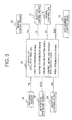
- FIG. 3 is a block diagram depicting the construction of an essential part of the drive system illustrated in FIG. 2 .
- the drive system 1 arranged in the hydraulic excavator is provided with the engine 2 electronically controlled in fuel injection quantity by an engine controller 3, the variable displacement hydraulic pump 4 drivable by power transmitted from the engine 2, and a pilot pump 6.
- the drive system 1 is also provided with a hydraulic actuator 7 drivable by pressure oil delivered from the variable displacement hydraulic pump 4 and an actuator control valve 8 for controlling pressure oil to be fed from the variable displacement hydraulic pump 4 to the hydraulic actuator 7.
- the actuator control valve 8 is switchable between a feed state, in which the pressure oil delivered from the variable displacement hydraulic pump 4 is fed to the hydraulic actuator 7, and a non-feed state, in which the pressure oil is not fed to the hydraulic actuator 7 but is returned to a hydraulic oil reservoir 9.
- the actuator control valve 8 is a 3-position valve. In a neutral position S out of its three valve positions, the actuator control valve 8 is in the non-feed state in which as illustrated in FIG. 1 , the pressure oil delivered from the variable displacement hydraulic pump 4 is returned to the hydraulic oil reservoir 9. In each of valve positions L,R on left and right sides of the neutral position S, the actuator control valve 8 is in the feed state in which the pressure oil delivered from the variable displacement hydraulic pump 4 is fed to the hydraulic actuator 7.
- the actuator control valve 8 is also a hydraulically-piloted valve.
- a pilot pressure to be applied to the actuator control valve 8 is produced by a control device 10, which includes a pilot valve, while using as a primary pressure a delivery pressure of the pilot pump 6.
- the actuator control valve 8 is switched from the neutral position S toward the valve position L when a pilot pressure is applied from the control device 10 to a first pressure receiving portion 8a via a first pilot line 11, but is conversely switched from the neutral position S toward the valve position R when a pilot pressure produced by the control device 10 is applied to a second pressure receiving portion 8b via a second pilot line 12.
- the first and second pilot lines 11,12 are connected to a high pressure selector valve 13.
- a pressure on a high pressure side as selected by the high pressure selector valve 13 is detected by a pressure sensor 14.
- This pressure sensor 14 is constructed to convert a detected pressure Pp to a pilot pressure signal (electrical signal), and is arranged to input this pilot pressure signal to a main controller 15.
- the engine 2 is provided with an exhaust pipe 16 through which exhaust gas is guided to an exterior of the hydraulic excavator.
- This exhaust pipe 16 is provided at an intermediate position thereof with an exhaust gas purification system 17 which traps, on a filter, particulate matter in exhaust gas produced by combustion in the engine 2.
- the exhaust pipe 16 is provided with a sensor means for detecting clogging of the filter of the exhaust gas purification system 17, specifically a differential pressure sensor 18 for detecting a differential pressure between an exhaust gas pressure on an upstream side of the exhaust gas purification system 17 and an exhaust gas pressure on a downstream side of the exhaust gas purification system 17.
- a sensor means for detecting clogging of the filter of the exhaust gas purification system 17 specifically a differential pressure sensor 18 for detecting a differential pressure between an exhaust gas pressure on an upstream side of the exhaust gas purification system 17 and an exhaust gas pressure on a downstream side of the exhaust gas purification system 17.
- the differential pressure sensor 18 detects a differential pressure indicating that the exhaust gas pressure on the upstream side is higher than that on the downstream side.
- the differential pressure sensor 18 is constructed to convert a detected differential pressure APe to a differential pressure signal (electrical signal). This differential pressure signal is inputted to the main controller 15.
- the variable displacement hydraulic pump 4 has a displacement varying mechanism 4a and a hydraulically-piloted regulator 4b.
- the displacement varying mechanism 4a enables to vary the displacement of the variable displacement hydraulic pump 4, and the hydraulically-piloted regulator 4b controls this displacement varying mechanism 4a.
- a pilot pressure to be applied to the regulator 4b is produced by a displacement control valve 19.
- the displacement control valve 19 Using a delivery pressure of the pilot pump 6 as a primary pressure, the displacement control valve 19 produces the pilot pressure.
- This displacement control valve 19 is a solenoid valve, and responsive to a displacement control signal (electric current) from the main controller 15, varies the pilot pressure to be applied to the regulator 4b.
- the hydraulic excavator according this embodiment is provided with an exhaust gas temperature raising processing means.
- the exhaust gas temperature raising processing means performs processing to increase a load acting on the engine 2 such that the temperature of the exhaust gas is raised to a temperature needed to burn the particulate matter contained in the exhaust gas.
- This exhaust gas temperature raising processing means includes an electric assist motor 5 connected to an output shaft of the engine 2, an inverter 20 for adjusting a torque of the electric assist motor 5, an inverter control device 21 drivable by a signal le outputted from the main controller 15 to control the inverter 20, and the above-mentioned main controller.
- the main controller 15 has CPU, ROM and RAM, and is provided with a first determination means and second determination means constructed by these CPU, ROM and RAM.
- the first determination means determines whether or not the actuator control valve 8 is in the non-feed state, while the second determination means determines whether or not clogging has occurred on the filter of the exhaust gas purification system 17.
- the main controller 15 outputs, to the inverter control device 21, a control signal for driving the electric assist motor 5 to increase the load acting on the engine 2 and another control signal for generating electric power by the electric assist motor 5.
- the inverter 20 converts, to a direct current, an alternating current generated by the electric assist motor 5, and also controls the output of electric power from the electric assist motor 5 by an electrical signal from the main controller 15 via the inverter control device 21.
- the hydraulic excavator according to this embodiment is also provided with a capacitor 24, a resistance wire (heating wire) 26, current branch circuits 22, and a branch control device 23.
- the capacitor 24 stores the electric power generated by the electric assist motor 5.
- the resistance wire (heating wire) 26 is arranged in the exhaust gas purification system 17 to heat and burn the particulate matter in the exhaust gas.
- the current branch circuits 22 selectively connect the inverter 20 and one of the capacitor 24 and resistance wire 26 to each other.
- the branch control device 23 is connected to the main controller 15 to control an operation of the current branch circuits 22.
- the main controller 15 includes a third determination means for determining whether or not the capacitor 24 is overcharged and, when the capacitor 24 is determined to be overcharged by the third determination means, performs processing to control the branch control device 23 such that the inverter 20 and the resistance wire 26 are connected to each other.
- the main controller 15 is provided, as mentioned above, with the first determination means for determining whether or not the actuator control valve 8 is in the non-feed state.
- This first determination means determines whether or not a detected pressure Pp indicated by a pilot pressure signal from the pressure sensor 14 is lower than a preset pressure Pps below which the actuator control valve 8 is to be actuated, in other words, whether a state of the actuator control valve 8 is the feed state, in which pressure oil from the variable displacement hydraulic pump 4 is fed to the hydraulic actuator 7, or the non-feed state, in which the pressure oil is not fed to the hydraulic actuator 7.
- the feed state corresponds to a working state in which work is being performed by the hydraulic excavator
- the non-feed state corresponds to a non-working state in which work is not being performed by the hydraulic excavator. It is, therefore, designed such that whether the hydraulic excavator is in a working state or in a non-working state can be detected by the high pressure selector valve 13, pressure sensor 14 and main controller 15.
- the main controller 15 is also provided with the second determination means for determining whether or not clogging has occurred on the filter of the exhaust gas purification system 17 as mentioned above.
- This second determination means determines whether or not a detected differential pressure ⁇ Pe indicated by a differential pressure signal from the differential pressure sensor 18 is not lower than a preset reference differential pressure APes.
- a detected differential pressure ⁇ Pe indicated by a differential pressure signal from the differential pressure sensor 18 is not lower than a preset reference differential pressure APes.
- a preset reference differential pressure APes As a result of clogging of the filter of the exhaust gas purification system 17, the flow path resistance to exhaust gas increases so that the detected differential pressure ⁇ Pe becomes higher. It is, therefore, designed such that clogging of the filter of the exhaust gas purification system 17 can be detected by the differential pressure sensor 18 and main controller 15.
- the main controller 15 is also provided with an engine rpm instruction means.
- This engine rpm instruction means delivers a preset first target rpm signal R1 to the engine controller 3.
- the first target rpm is, with a view to energy savings, an rpm set to lower the rpm of the engine 2 to a level needed for the variable displacement hydraulic pump 4 to deliver pressure oil at a lowest delivery rate required for cooling and lubricating a hydraulic circuit included in the drive system 1.
- the main controller 15 is also provided with a control means for the displacement control valve.
- This control means for the displacement control valve delivers a first displacement control signal DS1, which corresponds to a preset first displacement, to the displacement control valve 19.
- the regulator 4b operates the displacement varying mechanism 4a to set the displacement of the variable displacement hydraulic pump 4 at the first displacement.
- the variable displacement hydraulic pump 4 is driven by the engine 2 operated at the above-mentioned first target rpm in the state in which the variable displacement hydraulic pump 4 is set at the first displacement volume, the variable displacement hydraulic pump 4 delivers pressure oil at the above-mentioned lowest delivery rate.
- the main controller 15 is also provided with the third determination means for determining whether or not the capacitor 24 is overcharged as mentioned above.
- This third determination means determines whether or not the value We of a storage level signal Ce from a capacitor control device 25 is not smaller than an upper limit storage capacity Wes. In other words, the capacitor 24 is detected to be in a fully charged state by the main controller 15 and capacitor control device 25.
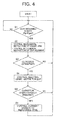
- FIG. 4 is a flow chart showing a processing routine in a main controller arranged in the drive system illustrated in FIG. 2 .
- the main controller 15 first functions as the first determination means for determining whether or not the actuator control valve 8 is in the non-feed state, and determines whether or not a detected pressure Pp indicated by a pilot pressure signal from the pilot pressure sensor 14 is lower than a preset pressure Pps (step S1). The main controller 15 repeatedly performs this determination at the first determination means in step S1 unless the detected pressure Pp drops below the preset pressure Pps, in other words, until the hydraulic excavator can be considered to be in the non-working state.
- the main controller 15 functions as the engine rpm instruction means and the control means for the displacement control valve, and delivers a first target rpm signal R1 to the engine controller 3 and also delivers a first displacement control signal DS1 to the displacement control valve 19 (step S2).
- the valve position of the actuator control valve 8 is the neutral position S.
- the main controller 15 functions as the second determination means for determining whether or not clogging has occurred on the filter of the exhaust gas purification system 17, and determines whether or not a detected differential pressure ⁇ Pe indicated by a differential pressure signal from the differential pressure sensor 18 is not smaller than the reference differential pressure ⁇ Pes (step S3).
- step S1 ⁇ step S2 ⁇ step S3 ⁇ step S1 is repeated.
- the main controller 15 delivers to the inverter control device 21 a target torque signal le for the electric assist motor, and increases the torque of the electric assist motor 5 to a preset target torque (step S4) .
- the load on the engine 2 increases so that the temperature of exhaust gas from the engine 2 rises, for example, to a lowest temperature needed to burn particulate matter trapped in the filter of the exhaust gas purification system 17.
- the electric assist motor 5 generates electric power by the load applied to the engine 2, and the resulting alternating current is converted by the inverter 20 to a direct current, which is then stored in the capacitor 24.
- the main controller 15 functions as the third determination means for determining whether or not the capacitor 24 is overcharged.
- the main controller 15 delivers a control signal to the branch control device 23 to perform control such that the inverter 20 and the resistance wire 26, which is arranged in the exhaust gas purification system 17, are connected to each other via the current branch circuits 22 (step S6).
- the resistance wire 26 generates heat, which is then utilized to burn the particulate matter in the exhaust gas as clogged on the filter of the exhaust gas purification system 17.
- the routine returns again to step S1, and the above-mentioned respective determinations and respective controls are continued.
- the main controller 15 drives the electric assist motor 5 such that the load acting on the engine 2 is increased.
- the generation of electric power is performed by the electric assist motor 5. Accordingly, the electric power by the electric power generation, in other words, the energy used to increase the load on the engine 2 upon burning the particulate matter in the exhaust gas can be recovered as electric power.
- the electric power can, therefore, be utilized to drive the hydraulic working machine, thereby making it possible to reduce the energy loss upon increasing the load on the engine 2 to burn the particulate matter.
- the lowest exhaust gas temperature sufficient to burn the particulate matter in the exhaust gas in other words, the minimum necessary temperature depends on the magnitude of the load on the engine 2, and the magnitude of the load on the engine 2 can be controlled with high accuracy by controlling the torque of the electric assist motor 5.
- this embodiment can, therefore, control the magnitude of the load on the engine 2 such that the minimum necessary temperature sufficient to burn the particulate matter can be maintained. In this respect, it is also possible to reduce the energy loss upon increasing the load on the engine 2 to burn the particulate matter.
- This embodiment can also drive the electric assist motor 5 to assist the driving of the engine 2 by feeding the electric power, which is stored in the capacitor 24, to the electric assist motor 5 via the inverter 20.
- the energy which is required to increase the load on the engine 2 upon burning the particulate matter, can be stored as electric power in the capacitor 24, and therefore, the electric power can be effectively utilized.
- This embodiment can also make the resistance wire 26, which is arranged in the exhaust gas purification system 17, generate heat by the electric power generated by the electric assist motor 5 when the storage level We of the capacitor 24 exceeds the upper limit storage capacity Wes. Therefore, the particulate matter in the exhaust gas can also be burnt with the heat generated by the resistance wire 26, thereby making it possible to improve the burning efficiency of the particulate matter in the exhaust gas.
Landscapes
- Engineering & Computer Science (AREA)
- Chemical & Material Sciences (AREA)
- Combustion & Propulsion (AREA)
- Mechanical Engineering (AREA)
- Transportation (AREA)
- General Engineering & Computer Science (AREA)
- Processes For Solid Components From Exhaust (AREA)
- Operation Control Of Excavators (AREA)
- Control Of Driving Devices And Active Controlling Of Vehicle (AREA)
- Component Parts Of Construction Machinery (AREA)
- Hybrid Electric Vehicles (AREA)
- Fluid-Pressure Circuits (AREA)
- Control Of Vehicle Engines Or Engines For Specific Uses (AREA)
Abstract
Description
- This invention relates to a hydraulic working machine, such as a hydraulic excavator, provided with an exhaust gas purification system for trapping particulate matter in exhaust gas produced from an engine.
- As a conventional technology of this kind, there is one disclosed in
Patent Document 1. The conventional technology disclosed inPatent Document 1 is provided with an engine, a variable displacement hydraulic pump drivable by power transmitted from the engine, and a hydraulic actuator drivable by pressure oil delivered from the variable displacement hydraulic pump. In addition, the conventional technology is also provided with an actuator control valve and an exhaust gas purification system. The actuator control valve controls a flow of pressure oil to be fed from the variable displacement hydraulic pump to the hydraulic actuator, and is switchable between a feed state in which the pressure oil delivered from the variable displacement hydraulic pump is to be fed to the hydraulic actuator and a non-feed state in which the pressure oil is returned to a hydraulic oil reservoir without feeding it to the hydraulic actuator. The exhaust gas purification system has a filter for trapping particulate matter in exhaust gas produced from the engine. Further, this conventional technology is also provided with an exhaust gas temperature raising processing means for performing, when the actuator control valve is in the above-mentioned non-feed state and clogging has occurred on the filter of the exhaust gas purification system, processing to increase a load acting on the engine such that a temperature of the exhaust gas is raised to a temperature needed to burn the particulate matter. This exhaust gas temperature raising processing means is configured to include a selector valve, which is openable or closable to communicate or cut off a line through which the pressure oil delivered from the variable displacement hydraulic pump is guided to the hydraulic oil reservoir. - According to this conventional technology, when the actuator control valve is in the non-feed state and clogging has occurred on the filter of the exhaust gas purification system, the selector valve is switchingly controlled to a closed position. As a consequence, the line that connects the variable displacement hydraulic pump and the hydraulic oil reservoir to each other is cut off, so that the pressure in a line section that connects the selector valve and the variable displacement hydraulic pump to each other, in other words, the pump delivery pressure becomes high, and therefore, the load acting on the engine increases. As a result, the temperature of exhaust gas from the engine rises to burn particulate matter contained in the exhaust gas.
- Patent Document 1:
JP-B-3073380 - When the burning of particulate matter in exhaust gas is needed, the above-mentioned conventional technology increases the load on the engine to raise the temperature of the exhaust gas so that the particulate matter in the exhaust gas can be burnt. However, the non-feed state of the actuator control valve corresponds to a non-working state in which work is not being performed by an actuation of the hydraulic actuator. Considering from the viewpoint of energy savings, it is, therefore, not desired to increase the load on the engine to increase the output of the engine in such a non-working state. With the foregoing in view, it has been desired to reduce an energy loss upon increasing the load on the engine to burn particulate matter during the non-feed state of the actuator control valve.
- It is also desired to raise the temperature of exhaust gas to a minimum necessary temperature sufficient to burn particulate matter upon increasing the load on the engine to raise the temperature of exhaust gas as mentioned above. With a technology that increases the pressure in a line section by closing control of a selector valve as in the conventional technology, there is, however, a tendency that the load on the engine increases more than necessary and the temperature of exhaust gas rises to a temperature higher than the minimum necessary temperature. In this respect, the conventional technology tends to produce an energy loss.
- With the above-mentioned actual situation of the conventional technology in view, the present invention has as an object thereof the provision of a hydraulic working machine capable of recovering, as electric power, energy to be used to increase a load on an engine upon burning particulate matter in exhaust gas.
- To achieve this object, the present invention is characterized in that in a hydraulic working machine provided with an engine, a variable displacement hydraulic pump drivable by power transmitted from the engine, a hydraulic actuator drivable by pressure oil delivered from the variable displacement hydraulic pump, an actuator control valve for controlling a flow of pressure oil, which is to be fed from the variable displacement hydraulic pump to the hydraulic actuator, topermit switching between a feed state inwhichpressure oil delivered from the variable displacement hydraulic pump is to be fed to the hydraulic actuator and a non-feed state in which the pressure oil is returned to a hydraulic oil reservoir without feeding the pressure oil to the hydraulic actuator, an exhaust gas purification system having a filter for trapping particulate matter in exhaust gas produced from the engine, and an exhaust gas temperature raising processing means for performing, when the actuator control valve is in the non-feed state and clogging has occurred on the filter, processing to increase a load acting on the engine such that a temperature of the exhaust gas is raised to a temperature needed to burn the particulate matter, the exhaust gas temperature raising processing means comprises an electric assist motor connected to an output shaft of the engine, an inverter for adjusting a torque of the electric assist motor, and an inverter control device for controlling the inverter; and a main controller having a first determination means for determining whether or not the actuator control valve is in the non-feed state and a second determination means for determining whether or not clogging has occurred on the filter of the exhaust gas purification system, wherein, when the non-feed state is determined by the first determination means and clogging is determined to have occurred on the filter by the second determination means , the main controller outputs, to the inverter control device, a control signal for driving the electric assist motor to increase the load acting on the engine and another control signal for generating electric power by the electric assist motor.
- According to the present invention constructed as described above, when the actuator control valve is determined to be in the non-feed state by the first determination means of the main controller, in other words, the hydraulic working machine is determined to be in a non-working state in which the hydraulic working machine is not performing work and clogging is determined to have occurred on the filter of the exhaust gas purification system by the second determination means, the main controller drives the electric assist motor to increase the load acting on the engine. At this time, the generation of electric power is performed by the electric assist motor. Accordingly, the electric power by the electric power generation, in other words, the energy to be used to increase the load on the engine upon burning particulate matter in exhaust gas can be recovered as electric power and the electric power can be utilized for driving the hydraulic working machine. Further, the lowest exhaust gas temperature sufficient to burn particulate matter in exhaust gas, in other words, the minimum necessary temperature depends on the magnitude of a load on the engine, and the magnitude of the load on the engine can be controlled with high accuracy by controlling the torque of the electric assist motor. In other words, upon burning particulate matter in exhaust gas as mentioned above, the present invention can control the load on the engine with high accuracy such that a minimum necessary temperature sufficient to burn the particulate matter can be maintained.
- The present invention may also be characterized in that in the above-described invention, the hydraulic working machine further comprises a capacitor for storing the electric power generated by the electric assist motor. The present invention constructed as described above can drive the electric assist motor to assist the driving of the engine by feeding the electric power, which is stored in the capacitor, to the electric assist motor via the inverter.
- The present invention may also be characterized in that in the above-described invention, the hydraulic working machine further comprises a resistance wire arranged in the exhaust gas purification system to burn the particulate matter in the exhaust gas, current branch circuits for selectively connecting the inverter and one of the capacitor and resistance wire to each other, and a branch control device connected to the main controller for controlling an operation of the current branch circuits, wherein the main controller comprises a third determination means for determining whether or not the capacitor is overcharged and, when the capacitor is determined to be overcharged by the third determination means, the main controller performs processing to control the branch control device such that the inverter and the resistance wire are connected to each other.
- According to the present invention constructed as described above, the resistance wire arranged in the exhaust gas purification system can be made to generate heat by the electric power generated by the electric assist motor when the storage level of the capacitor exceeds the upper limit storage capacity. Therefore, the particulate matter in the exhaust gas can also be burnt by the production of heat from the resistance wire.
- As the exhaust gas temperature raising processing means is configured to comprise the electric assist motor connected to the output shaft of the engine, the inverter for adjusting the torque of the electric assist motor, the inverter control device for controlling the inverter, and the main controller for controlling the inverter control device, the present invention makes it possible to recover, as electric power available from electric power generation by the electric assist motor, energy to be used to increase the load on the engine upon burning the particulate matter in exhaust gas. Therefore, this electric power can be utilized for driving the hydraulic working machine, thereby making it possible to reduce, compared with before, the energy loss upon increasing the load on the engine to burn the particulate matter. Upon burning the particulate matter in the exhaust gas, the output of the engine can be controlled with high accuracy to maintain a minimum necessary temperature sufficient to burn the particulate matter in the exhaust gas by controlling the electric assist motor via the inverter. In this respect, it is also possible to reduce, compared with before, the energy loss upon increasing the load on the engine to burn the particulate matter.
-
-
FIG. 1 is a side view showing a hydraulic excavator as one embodiment of the hydraulic working machine. -
FIG. 2 is a circuit diagram illustrating a drive system arranged in the hydraulic excavator according to this embodiment. -
FIG. 3 is a block diagram depicting the construction of an essential part of the drive system illustrated inFIG. 2 . -
FIG. 4 is a flow chart showing a processing routine in a main controller arranged in the drive system illustrated inFIG. 2 . - One embodiment of the hydraulic working machine according to the present invention will hereinafter be described with reference to the drawings.
-
FIG. 1 is a side view showing a hydraulic excavator as one embodiment of the hydraulic working machine. As shown inFIG. 1 , the hydraulic excavator according to this embodiment is provided with atravel base 30, anupperstructure 31 arranged on thetravel base 30, andworking equipment 32 attached tiltably in an up-and-down direction to theupperstructure 31. Theworking equipment 32 includes aboom 33 attached tiltably in the up-and-down direction to theupperstructure 31, anarm 34 attached tiltably in the up-and-down direction to a free end of theboom 33, and abucket 35 attached tiltably in the up-and-down direction to a free end of thearm 34. In addition, theworking equipment 32 also includes hydraulic cylinders, specifically hydraulic actuators such as aboom cylinder 33a for actuating theboom 33, anarm cylinder 34a for actuating thearm 34, and abucket cylinder 35a for actuating thebucket 35. An operator'scab 36 is arranged on theupperstructure 31 at a forward position thereof, and acounterweight 37 is arranged on theupperstructure 31 at a rear position thereof. Arranged between the operator'scab 36 and thecounterweight 37 is anengine compartment 38, in which anengine 2, a variable displacementhydraulic pump 4 and the like, which will be described subsequently herein, are accommodated. -
FIG. 2 is a circuit diagram illustrating a drive system arranged in the hydraulic excavator according to this embodiment, andFIG. 3 is a block diagram depicting the construction of an essential part of the drive system illustrated inFIG. 2 . - As shown in
FIG. 2 , thedrive system 1 arranged in the hydraulic excavator according to this embodiment is provided with theengine 2 electronically controlled in fuel injection quantity by anengine controller 3, the variable displacementhydraulic pump 4 drivable by power transmitted from theengine 2, and apilot pump 6. In addition, thedrive system 1 is also provided with a hydraulic actuator 7 drivable by pressure oil delivered from the variable displacementhydraulic pump 4 and anactuator control valve 8 for controlling pressure oil to be fed from the variable displacementhydraulic pump 4 to the hydraulic actuator 7. Theactuator control valve 8 is switchable between a feed state, in which the pressure oil delivered from the variable displacementhydraulic pump 4 is fed to the hydraulic actuator 7, and a non-feed state, in which the pressure oil is not fed to the hydraulic actuator 7 but is returned to ahydraulic oil reservoir 9. It is to be noted that only the single actuator 7 is illustrated to facilitate the description although the hydraulic excavator is provided with various hydraulic actuators such as unillustrated swing motor and travel motors in addition to hydraulic cylinders such as the above-mentionedboom cylinder 33a andarm cylinder 34a. Concerning actuator control valves actually arranged for the hydraulic actuators, respectively, only the singleactuator control valve 8 is correspondingly illustrated to facilitate the description. - The
actuator control valve 8 is a 3-position valve. In a neutral position S out of its three valve positions, theactuator control valve 8 is in the non-feed state in which as illustrated inFIG. 1 , the pressure oil delivered from the variable displacementhydraulic pump 4 is returned to thehydraulic oil reservoir 9. In each of valve positions L,R on left and right sides of the neutral position S, theactuator control valve 8 is in the feed state in which the pressure oil delivered from the variable displacementhydraulic pump 4 is fed to the hydraulic actuator 7. - The
actuator control valve 8 is also a hydraulically-piloted valve. A pilot pressure to be applied to theactuator control valve 8 is produced by a control device 10, which includes a pilot valve, while using as a primary pressure a delivery pressure of thepilot pump 6. Theactuator control valve 8 is switched from the neutral position S toward the valve position L when a pilot pressure is applied from the control device 10 to a firstpressure receiving portion 8a via afirst pilot line 11, but is conversely switched from the neutral position S toward the valve position R when a pilot pressure produced by the control device 10 is applied to a secondpressure receiving portion 8b via asecond pilot line 12. - The first and
second pilot lines pressure selector valve 13. A pressure on a high pressure side as selected by the highpressure selector valve 13 is detected by apressure sensor 14. Thispressure sensor 14 is constructed to convert a detected pressure Pp to a pilot pressure signal (electrical signal), and is arranged to input this pilot pressure signal to amain controller 15. - The
engine 2 is provided with anexhaust pipe 16 through which exhaust gas is guided to an exterior of the hydraulic excavator. Thisexhaust pipe 16 is provided at an intermediate position thereof with an exhaustgas purification system 17 which traps, on a filter, particulate matter in exhaust gas produced by combustion in theengine 2. - The
exhaust pipe 16 is provided with a sensor means for detecting clogging of the filter of the exhaustgas purification system 17, specifically adifferential pressure sensor 18 for detecting a differential pressure between an exhaust gas pressure on an upstream side of the exhaustgas purification system 17 and an exhaust gas pressure on a downstream side of the exhaustgas purification system 17. When the clogging amount of the filter of the exhaustgas purification system 17 increases, the flow path resistance to the exhaust gas increases so that the exhaust gas pressure on the upstream side becomes higher than the exhaust gas pressure on the downstream side. Accordingly, thedifferential pressure sensor 18 detects a differential pressure indicating that the exhaust gas pressure on the upstream side is higher than that on the downstream side. Thedifferential pressure sensor 18 is constructed to convert a detected differential pressure APe to a differential pressure signal (electrical signal). This differential pressure signal is inputted to themain controller 15. - The variable displacement
hydraulic pump 4 has adisplacement varying mechanism 4a and a hydraulically-pilotedregulator 4b. Thedisplacement varying mechanism 4a enables to vary the displacement of the variable displacementhydraulic pump 4, and the hydraulically-pilotedregulator 4b controls thisdisplacement varying mechanism 4a. A pilot pressure to be applied to theregulator 4b is produced by adisplacement control valve 19. Using a delivery pressure of thepilot pump 6 as a primary pressure, thedisplacement control valve 19 produces the pilot pressure. Thisdisplacement control valve 19 is a solenoid valve, and responsive to a displacement control signal (electric current) from themain controller 15, varies the pilot pressure to be applied to theregulator 4b. - The hydraulic excavator according this embodiment is provided with an exhaust gas temperature raising processing means. When the
actuator control valve 8 is in the non-feed state and clogging has occurred on the filter of the exhaustgas purification system 17, the exhaust gas temperature raising processing means performs processing to increase a load acting on theengine 2 such that the temperature of the exhaust gas is raised to a temperature needed to burn the particulate matter contained in the exhaust gas. This exhaust gas temperature raising processing means includes anelectric assist motor 5 connected to an output shaft of theengine 2, aninverter 20 for adjusting a torque of theelectric assist motor 5, aninverter control device 21 drivable by a signal le outputted from themain controller 15 to control theinverter 20, and the above-mentioned main controller. Themain controller 15 has CPU, ROM and RAM, and is provided with a first determination means and second determination means constructed by these CPU, ROM and RAM. The first determination means determines whether or not theactuator control valve 8 is in the non-feed state, while the second determination means determines whether or not clogging has occurred on the filter of the exhaustgas purification system 17. When the non-feed state is determined by the first determination means and clogging is determined to have occurred on the filter by the second determination means, themain controller 15 outputs, to theinverter control device 21, a control signal for driving theelectric assist motor 5 to increase the load acting on theengine 2 and another control signal for generating electric power by theelectric assist motor 5. - The
inverter 20 converts, to a direct current, an alternating current generated by theelectric assist motor 5, and also controls the output of electric power from theelectric assist motor 5 by an electrical signal from themain controller 15 via theinverter control device 21. - Further, the hydraulic excavator according to this embodiment is also provided with a
capacitor 24, a resistance wire (heating wire) 26,current branch circuits 22, and abranch control device 23. Thecapacitor 24 stores the electric power generated by theelectric assist motor 5. The resistance wire (heating wire) 26 is arranged in the exhaustgas purification system 17 to heat and burn the particulate matter in the exhaust gas. Thecurrent branch circuits 22 selectively connect theinverter 20 and one of thecapacitor 24 andresistance wire 26 to each other. Thebranch control device 23 is connected to themain controller 15 to control an operation of thecurrent branch circuits 22. In addition, themain controller 15 includes a third determination means for determining whether or not thecapacitor 24 is overcharged and, when thecapacitor 24 is determined to be overcharged by the third determination means, performs processing to control thebranch control device 23 such that theinverter 20 and theresistance wire 26 are connected to each other. - The
main controller 15 is provided, as mentioned above, with the first determination means for determining whether or not theactuator control valve 8 is in the non-feed state. This first determination means determines whether or not a detected pressure Pp indicated by a pilot pressure signal from thepressure sensor 14 is lower than a preset pressure Pps below which theactuator control valve 8 is to be actuated, in other words, whether a state of theactuator control valve 8 is the feed state, in which pressure oil from the variable displacementhydraulic pump 4 is fed to the hydraulic actuator 7, or the non-feed state, in which the pressure oil is not fed to the hydraulic actuator 7. The feed state corresponds to a working state in which work is being performed by the hydraulic excavator, while the non-feed state corresponds to a non-working state in which work is not being performed by the hydraulic excavator. It is, therefore, designed such that whether the hydraulic excavator is in a working state or in a non-working state can be detected by the highpressure selector valve 13,pressure sensor 14 andmain controller 15. - Further, the
main controller 15 is also provided with the second determination means for determining whether or not clogging has occurred on the filter of the exhaustgas purification system 17 as mentioned above. This second determination means determines whether or not a detected differential pressure ΔPe indicated by a differential pressure signal from thedifferential pressure sensor 18 is not lower than a preset reference differential pressure APes. As a result of clogging of the filter of the exhaustgas purification system 17, the flow path resistance to exhaust gas increases so that the detected differential pressure ΔPe becomes higher. It is, therefore, designed such that clogging of the filter of the exhaustgas purification system 17 can be detected by thedifferential pressure sensor 18 andmain controller 15. - The
main controller 15 is also provided with an engine rpm instruction means. This engine rpm instruction means delivers a preset first target rpm signal R1 to theengine controller 3. The first target rpm is, with a view to energy savings, an rpm set to lower the rpm of theengine 2 to a level needed for the variable displacementhydraulic pump 4 to deliver pressure oil at a lowest delivery rate required for cooling and lubricating a hydraulic circuit included in thedrive system 1. - The
main controller 15 is also provided with a control means for the displacement control valve. This control means for the displacement control valve delivers a first displacement control signal DS1, which corresponds to a preset first displacement, to thedisplacement control valve 19. When thedisplacement control valve 19 applies to theregulator 4b a pilot pressure responsive to the first displacement control signal DS1, theregulator 4b operates thedisplacement varying mechanism 4a to set the displacement of the variable displacementhydraulic pump 4 at the first displacement. When the variable displacementhydraulic pump 4 is driven by theengine 2 operated at the above-mentioned first target rpm in the state in which the variable displacementhydraulic pump 4 is set at the first displacement volume, the variable displacementhydraulic pump 4 delivers pressure oil at the above-mentioned lowest delivery rate. - The
main controller 15 is also provided with the third determination means for determining whether or not thecapacitor 24 is overcharged as mentioned above. This third determination means determines whether or not the value We of a storage level signal Ce from acapacitor control device 25 is not smaller than an upper limit storage capacity Wes. In other words, thecapacitor 24 is detected to be in a fully charged state by themain controller 15 andcapacitor control device 25. -
FIG. 4 is a flow chart showing a processing routine in a main controller arranged in the drive system illustrated inFIG. 2 . - The
main controller 15 first functions as the first determination means for determining whether or not theactuator control valve 8 is in the non-feed state, and determines whether or not a detected pressure Pp indicated by a pilot pressure signal from thepilot pressure sensor 14 is lower than a preset pressure Pps (step S1). Themain controller 15 repeatedly performs this determination at the first determination means in step S1 unless the detected pressure Pp drops below the preset pressure Pps, in other words, until the hydraulic excavator can be considered to be in the non-working state. - When the determination at the first determination means results in "YES" and the non-working state is indicated, the
main controller 15 functions as the engine rpm instruction means and the control means for the displacement control valve, and delivers a first target rpm signal R1 to theengine controller 3 and also delivers a first displacement control signal DS1 to the displacement control valve 19 (step S2). At this time, the valve position of theactuator control valve 8 is the neutral position S. When the rpm of theengine 2 reaches the first target rpm and the displacement reaches the first displacement, the variable displacementhydraulic pump 4 is, therefore, brought to a state in which pressure oil is delivered at a lowest delivery pressure and a lowest delivery rate required for cooling and lubricating the hydraulic circuit included in thedrive system 1. - In the state as described above, the
main controller 15 functions as the second determination means for determining whether or not clogging has occurred on the filter of the exhaustgas purification system 17, and determines whether or not a detected differential pressure ΔPe indicated by a differential pressure signal from thedifferential pressure sensor 18 is not smaller than the reference differential pressure ΔPes (step S3). When no clogging has occurred on the filter of the exhaustgas purification system 17, step S1→step S2→step S3→step S1 is repeated. - When the detected differential pressure ΔPe is determined to be not lower than the reference differential pressure APes in step S3, that is, clogging has occurred on the filter of the exhaust
gas purification system 17, themain controller 15 delivers to the inverter control device 21 a target torque signal le for the electric assist motor, and increases the torque of theelectric assist motor 5 to a preset target torque (step S4) . As a result of the increase in the torque of theelectric assist motor 5, the load on theengine 2 increases so that the temperature of exhaust gas from theengine 2 rises, for example, to a lowest temperature needed to burn particulate matter trapped in the filter of the exhaustgas purification system 17. During this time, theelectric assist motor 5 generates electric power by the load applied to theengine 2, and the resulting alternating current is converted by theinverter 20 to a direct current, which is then stored in thecapacitor 24. - In the state as described above, the
main controller 15 functions as the third determination means for determining whether or not thecapacitor 24 is overcharged. When a detected storage level We of thecapacitor 24 exceeds the upper limit storage capacity Wes, themain controller 15 delivers a control signal to thebranch control device 23 to perform control such that theinverter 20 and theresistance wire 26, which is arranged in the exhaustgas purification system 17, are connected to each other via the current branch circuits 22 (step S6). As a result, theresistance wire 26 generates heat, which is then utilized to burn the particulate matter in the exhaust gas as clogged on the filter of the exhaustgas purification system 17. After this step S6, the routine returns again to step S1, and the above-mentioned respective determinations and respective controls are continued. - According to the hydraulic excavator of this embodiment constructed as described above, when the
actuator control valve 8 is determined to be in the non-feed state by the first determination means of themain controller 15, in other words, the hydraulic excavator is determined to be in the non-working state and clogging is determined to have occurred on the filter of the exhaustgas purification system 17 by the second determination means, themain controller 15 drives theelectric assist motor 5 such that the load acting on theengine 2 is increased. At this time, the generation of electric power is performed by theelectric assist motor 5. Accordingly, the electric power by the electric power generation, in other words, the energy used to increase the load on theengine 2 upon burning the particulate matter in the exhaust gas can be recovered as electric power. The electric power can, therefore, be utilized to drive the hydraulic working machine, thereby making it possible to reduce the energy loss upon increasing the load on theengine 2 to burn the particulate matter. The lowest exhaust gas temperature sufficient to burn the particulate matter in the exhaust gas, in other words, the minimum necessary temperature depends on the magnitude of the load on theengine 2, and the magnitude of the load on theengine 2 can be controlled with high accuracy by controlling the torque of theelectric assist motor 5. Upon burning the particulate matter in the exhaust gas as mentioned above, this embodiment can, therefore, control the magnitude of the load on theengine 2 such that the minimum necessary temperature sufficient to burn the particulate matter can be maintained. In this respect, it is also possible to reduce the energy loss upon increasing the load on theengine 2 to burn the particulate matter. - This embodiment can also drive the
electric assist motor 5 to assist the driving of theengine 2 by feeding the electric power, which is stored in thecapacitor 24, to theelectric assist motor 5 via theinverter 20. In other words, the energy, which is required to increase the load on theengine 2 upon burning the particulate matter, can be stored as electric power in thecapacitor 24, and therefore, the electric power can be effectively utilized. - This embodiment can also make the
resistance wire 26, which is arranged in the exhaustgas purification system 17, generate heat by the electric power generated by theelectric assist motor 5 when the storage level We of thecapacitor 24 exceeds the upper limit storage capacity Wes. Therefore, the particulate matter in the exhaust gas can also be burnt with the heat generated by theresistance wire 26, thereby making it possible to improve the burning efficiency of the particulate matter in the exhaust gas. - 1
Legend 1 Drive system 2 Engine 4 Variable displacement hydraulic pump 5 Electric assist motor 7 Hydraulic actuator 8 Actuator control valve 9 Hydraulic oil reservoir 10 Control device 11 First pilot line 12 Second pilot line 13 High pressure selector valve 14 Pressure sensor 15 Main controller 16 Exhaust pipe 17 Exhaust gas purification system 18 Differential pressure sensor 20 Inverter 21 Inverter control device 22 Current branch circuits 23 Branch control device 24 Capacitor 25 Capacitor control device 26 Resistance wire 30 Travel base 31 Upperstructure 32 Working equipment We Storage level Wes Upper limit storage capacity Pp Detected pressure Pps Preset pressure APe Detected differential pressure APes Reference differential pressure
Claims (3)
- A hydraulic working machine provided with an engine, a variable displacement hydraulic pump drivable by power transmitted from the engine, a hydraulic actuator drivable by pressure oil delivered from the variable displacement hydraulic pump, an actuator control valve for controlling a flow of pressure oil, which is to be fed from the variable displacement hydraulic pump to the hydraulic actuator, to permit switching between a feed state in which pressure oil delivered from the variable displacement hydraulic pump is to be fed to the hydraulic actuator and a non-feed state in which the pressure oil is returned to a hydraulic oil reservoir without feeding the pressure oil to the hydraulic actuator, an exhaust gas purification system having a filter for trapping particulate matter in exhaust gas produced from the engine, and an exhaust gas temperature raising processing means for performing, when the actuator control valve is in the non-feed state and clogging has occurred on the filter, processing to increase a load acting on the engine such that a temperature of the exhaust gas is raised to a temperature needed to burn the particulate matter, wherein the exhaust gas temperature raising processing means comprises:an electric assist motor connected to an output shaft of the engine, an inverter for adjusting a torque of the electric assist motor, and an inverter control device for controlling the inverter; anda main controller having a first determination means for determining whether or not the actuator control valve is in the non-feed state and a second determination means for determining whether or not clogging has occurred on the filter of the exhaust gas purification system, wherein, when the non-feed state is determined by the first determination means and clogging is determined to have occurred on the filter by the second determination means, the main controller outputs, to the inverter control device, a control signal for driving the electric assist motor to increase the load acting on the engine and another control signal for generating electric power by the electric assist motor.
- The hydraulic working machine according to claim 1, further comprising a capacitor for storing the electric power generated by the electric assist motor.
- The hydraulic working machine according to claim 2, further comprising:a resistance wire arranged in the exhaust gas purification system to burn the particulate matter in the exhaust gas,current branch circuits for selectively connecting the inverter and one of the capacitor and resistance wire to each other, anda branch control device connected to the main controller for controlling an operation of the current branch circuits,wherein the main controller comprises a third determination means for determining whether or not the capacitor is overcharged and, when the capacitor is determined to be overcharged by the third determination means, performing processing to control the branch control device such that the inverter and the resistance wire are connected to each other.
Applications Claiming Priority (2)
| Application Number | Priority Date | Filing Date | Title |
|---|---|---|---|
| JP2010194193A JP5539116B2 (en) | 2010-08-31 | 2010-08-31 | Hydraulic working machine |
| PCT/JP2011/069185 WO2012029628A1 (en) | 2010-08-31 | 2011-08-25 | Hydraulic working machine |
Publications (3)
| Publication Number | Publication Date |
|---|---|
| EP2613031A1 true EP2613031A1 (en) | 2013-07-10 |
| EP2613031A4 EP2613031A4 (en) | 2018-01-03 |
| EP2613031B1 EP2613031B1 (en) | 2022-03-02 |
Family
ID=45772720
Family Applications (1)
| Application Number | Title | Priority Date | Filing Date |
|---|---|---|---|
| EP11821645.6A Not-in-force EP2613031B1 (en) | 2010-08-31 | 2011-08-25 | Hydraulic working machine |
Country Status (6)
| Country | Link |
|---|---|
| US (1) | US9038375B2 (en) |
| EP (1) | EP2613031B1 (en) |
| JP (1) | JP5539116B2 (en) |
| KR (1) | KR101759763B1 (en) |
| CN (1) | CN103080487B (en) |
| WO (1) | WO2012029628A1 (en) |
Cited By (2)
| Publication number | Priority date | Publication date | Assignee | Title |
|---|---|---|---|---|
| EP3366508A1 (en) * | 2017-02-24 | 2018-08-29 | Toyota Jidosha Kabushiki Kaisha | Hybrid vehicle |
| EP3269953A4 (en) * | 2015-03-13 | 2018-10-31 | Hitachi Construction Machinery Co., Ltd. | Control device for hybrid construction machine |
Families Citing this family (5)
| Publication number | Priority date | Publication date | Assignee | Title |
|---|---|---|---|---|
| JP5248377B2 (en) * | 2009-03-16 | 2013-07-31 | 日立建機株式会社 | Hydraulic drive device for work machine |
| JP5998095B2 (en) * | 2013-03-29 | 2016-09-28 | ヤンマー株式会社 | Hybrid drive |
| US10989052B2 (en) * | 2017-02-14 | 2021-04-27 | Kolberg-Pioneer, Inc. | Apparatus and method for a dual power system |
| EP3863043A4 (en) | 2018-10-04 | 2021-11-03 | Toyo Tanso Co., Ltd. | SUSCEPTOR |
| GB2598352B (en) * | 2020-08-27 | 2024-07-17 | Bamford Excavators Ltd | A control system |
Family Cites Families (13)
| Publication number | Priority date | Publication date | Assignee | Title |
|---|---|---|---|---|
| JPS62251110A (en) | 1986-04-25 | 1987-10-31 | Eagle Ind Co Ltd | Forming method for wax prototype of sliding ring of floating seal |
| JPH06212949A (en) | 1993-01-20 | 1994-08-02 | Isuzu Ceramics Kenkyusho:Kk | Diesel particulate filter and power supply |
| JP3073380B2 (en) * | 1993-12-17 | 2000-08-07 | 日立建機株式会社 | Hydraulic working machine equipped with exhaust gas purification device |
| JP2001011888A (en) | 1999-06-29 | 2001-01-16 | Kobe Steel Ltd | Excavator |
| US20050155345A1 (en) * | 2002-03-29 | 2005-07-21 | Tokyo Electron Limited | Device and method for purifying exhaust gas from industrial vehicle engine |
| JP2004092428A (en) * | 2002-08-29 | 2004-03-25 | Fuji Heavy Ind Ltd | Hybrid vehicle control device |
| JP4100440B2 (en) * | 2006-09-26 | 2008-06-11 | トヨタ自動車株式会社 | Control device for hybrid vehicle |
| JP4897612B2 (en) * | 2007-08-13 | 2012-03-14 | 日立建機株式会社 | Work machine |
| JP4257800B1 (en) * | 2007-10-09 | 2009-04-22 | アイシン・エィ・ダブリュ株式会社 | Hybrid drive device |
| JP4806390B2 (en) * | 2007-12-04 | 2011-11-02 | 日立建機株式会社 | Work machine |
| JP5101436B2 (en) * | 2008-08-26 | 2012-12-19 | ヤンマー株式会社 | diesel engine |
| JP5293009B2 (en) * | 2008-09-01 | 2013-09-18 | コベルコ建機株式会社 | Construction machine control equipment |
| JP5160359B2 (en) * | 2008-09-26 | 2013-03-13 | 住友重機械工業株式会社 | Hybrid construction machine |
-
2010
- 2010-08-31 JP JP2010194193A patent/JP5539116B2/en not_active Expired - Fee Related
-
2011
- 2011-08-25 WO PCT/JP2011/069185 patent/WO2012029628A1/en not_active Ceased
- 2011-08-25 KR KR1020137007677A patent/KR101759763B1/en not_active Expired - Fee Related
- 2011-08-25 US US13/819,375 patent/US9038375B2/en active Active
- 2011-08-25 CN CN201180041814.4A patent/CN103080487B/en not_active Expired - Fee Related
- 2011-08-25 EP EP11821645.6A patent/EP2613031B1/en not_active Not-in-force
Non-Patent Citations (1)
| Title |
|---|
| See references of WO2012029628A1 * |
Cited By (3)
| Publication number | Priority date | Publication date | Assignee | Title |
|---|---|---|---|---|
| EP3269953A4 (en) * | 2015-03-13 | 2018-10-31 | Hitachi Construction Machinery Co., Ltd. | Control device for hybrid construction machine |
| US10538236B2 (en) | 2015-03-13 | 2020-01-21 | Hitachi Construction Machinery Co., Ltd. | Control apparatus for hybrid construction machine |
| EP3366508A1 (en) * | 2017-02-24 | 2018-08-29 | Toyota Jidosha Kabushiki Kaisha | Hybrid vehicle |
Also Published As
| Publication number | Publication date |
|---|---|
| US20130209283A1 (en) | 2013-08-15 |
| WO2012029628A1 (en) | 2012-03-08 |
| KR20130138224A (en) | 2013-12-18 |
| JP5539116B2 (en) | 2014-07-02 |
| JP2012052442A (en) | 2012-03-15 |
| KR101759763B1 (en) | 2017-07-19 |
| EP2613031A4 (en) | 2018-01-03 |
| CN103080487B (en) | 2015-06-17 |
| US9038375B2 (en) | 2015-05-26 |
| EP2613031B1 (en) | 2022-03-02 |
| CN103080487A (en) | 2013-05-01 |
Similar Documents
| Publication | Publication Date | Title |
|---|---|---|
| EP2613031B1 (en) | Hydraulic working machine | |
| US9010088B2 (en) | Working machine | |
| CN103991378B (en) | Control method of hybrid type working machine | |
| US9637890B2 (en) | Power transmission device and hybrid construction machine provided therewith | |
| EP2320093B1 (en) | Engine lug-down suppressing device for hydraulic work machinery | |
| CN103765019B (en) | The fluid pressure drive device of engineering machinery | |
| KR101429375B1 (en) | Drive control method for operating machine | |
| EP2407648B1 (en) | Hydraulic driving device for work machine | |
| US8695566B2 (en) | Engine control apparatus | |
| EP2730704B1 (en) | Regenerative hydraulic circuit for a shovel and method for controlling a shovel | |
| JP6022461B2 (en) | Excavator and control method of excavator | |
| EP3578830A1 (en) | Construction machine | |
| KR101948322B1 (en) | Power regeneration device for work machine | |
| EP3358201B1 (en) | Pressure oil energy regeneration device of work machine | |
| KR101590277B1 (en) | Engine control apparatus and construction machine | |
| EP2770119A1 (en) | Hybrid-driven hydraulic work machine | |
| EP2474739A1 (en) | Hydraulic drive device of hydraulic operating machine | |
| CN107429714B (en) | Hydraulic drive system for construction machinery | |
| EP3591241A1 (en) | Work machine | |
| KR20120110153A (en) | Hybrid construction machine | |
| JP7460604B2 (en) | excavator | |
| CN110506165B (en) | Construction machine |
Legal Events
| Date | Code | Title | Description |
|---|---|---|---|
| PUAI | Public reference made under article 153(3) epc to a published international application that has entered the european phase |
Free format text: ORIGINAL CODE: 0009012 |
|
| 17P | Request for examination filed |
Effective date: 20130402 |
|
| AK | Designated contracting states |
Kind code of ref document: A1 Designated state(s): AL AT BE BG CH CY CZ DE DK EE ES FI FR GB GR HR HU IE IS IT LI LT LU LV MC MK MT NL NO PL PT RO RS SE SI SK SM TR |
|
| DAX | Request for extension of the european patent (deleted) | ||
| RA4 | Supplementary search report drawn up and despatched (corrected) |
Effective date: 20171201 |
|
| RIC1 | Information provided on ipc code assigned before grant |
Ipc: F04B 7/00 20060101ALI20171127BHEP Ipc: B60K 6/485 20071001ALI20171127BHEP Ipc: F01N 3/02 20060101AFI20171127BHEP Ipc: B60W 10/20 20060101ALI20171127BHEP Ipc: B60W 10/06 20060101ALI20171127BHEP Ipc: B60K 6/22 20071001ALI20171127BHEP Ipc: B60W 10/08 20060101ALI20171127BHEP Ipc: F01N 9/00 20060101ALI20171127BHEP |
|
| RIC1 | Information provided on ipc code assigned before grant |
Ipc: F04B 7/00 20060101ALI20171127BHEP Ipc: F01N 3/02 20060101AFI20171127BHEP Ipc: B60W 10/08 20060101ALI20171127BHEP Ipc: B60K 6/485 20071001ALI20171127BHEP Ipc: F01N 9/00 20060101ALI20171127BHEP Ipc: B60K 6/22 20071001ALI20171127BHEP Ipc: B60W 10/20 20060101ALI20171127BHEP Ipc: B60W 10/06 20060101ALI20171127BHEP |
|
| STAA | Information on the status of an ep patent application or granted ep patent |
Free format text: STATUS: EXAMINATION IS IN PROGRESS |
|
| 17Q | First examination report despatched |
Effective date: 20201105 |
|
| GRAP | Despatch of communication of intention to grant a patent |
Free format text: ORIGINAL CODE: EPIDOSNIGR1 |
|
| STAA | Information on the status of an ep patent application or granted ep patent |
Free format text: STATUS: GRANT OF PATENT IS INTENDED |
|
| INTG | Intention to grant announced |
Effective date: 20210909 |
|
| GRAS | Grant fee paid |
Free format text: ORIGINAL CODE: EPIDOSNIGR3 |
|
| GRAA | (expected) grant |
Free format text: ORIGINAL CODE: 0009210 |
|
| STAA | Information on the status of an ep patent application or granted ep patent |
Free format text: STATUS: THE PATENT HAS BEEN GRANTED |
|
| AK | Designated contracting states |
Kind code of ref document: B1 Designated state(s): AL AT BE BG CH CY CZ DE DK EE ES FI FR GB GR HR HU IE IS IT LI LT LU LV MC MK MT NL NO PL PT RO RS SE SI SK SM TR |
|
| REG | Reference to a national code |
Ref country code: GB Ref legal event code: FG4D |
|
| REG | Reference to a national code |
Ref country code: CH Ref legal event code: EP Ref country code: AT Ref legal event code: REF Ref document number: 1472403 Country of ref document: AT Kind code of ref document: T Effective date: 20220315 |
|
| REG | Reference to a national code |
Ref country code: DE Ref legal event code: R096 Ref document number: 602011072564 Country of ref document: DE |
|
| REG | Reference to a national code |
Ref country code: IE Ref legal event code: FG4D |
|
| REG | Reference to a national code |
Ref country code: LT Ref legal event code: MG9D |
|
| REG | Reference to a national code |
Ref country code: NL Ref legal event code: MP Effective date: 20220302 |
|
| PG25 | Lapsed in a contracting state [announced via postgrant information from national office to epo] |
Ref country code: SE Free format text: LAPSE BECAUSE OF FAILURE TO SUBMIT A TRANSLATION OF THE DESCRIPTION OR TO PAY THE FEE WITHIN THE PRESCRIBED TIME-LIMIT Effective date: 20220302 Ref country code: RS Free format text: LAPSE BECAUSE OF FAILURE TO SUBMIT A TRANSLATION OF THE DESCRIPTION OR TO PAY THE FEE WITHIN THE PRESCRIBED TIME-LIMIT Effective date: 20220302 Ref country code: NO Free format text: LAPSE BECAUSE OF FAILURE TO SUBMIT A TRANSLATION OF THE DESCRIPTION OR TO PAY THE FEE WITHIN THE PRESCRIBED TIME-LIMIT Effective date: 20220602 Ref country code: LT Free format text: LAPSE BECAUSE OF FAILURE TO SUBMIT A TRANSLATION OF THE DESCRIPTION OR TO PAY THE FEE WITHIN THE PRESCRIBED TIME-LIMIT Effective date: 20220302 Ref country code: HR Free format text: LAPSE BECAUSE OF FAILURE TO SUBMIT A TRANSLATION OF THE DESCRIPTION OR TO PAY THE FEE WITHIN THE PRESCRIBED TIME-LIMIT Effective date: 20220302 Ref country code: ES Free format text: LAPSE BECAUSE OF FAILURE TO SUBMIT A TRANSLATION OF THE DESCRIPTION OR TO PAY THE FEE WITHIN THE PRESCRIBED TIME-LIMIT Effective date: 20220302 Ref country code: BG Free format text: LAPSE BECAUSE OF FAILURE TO SUBMIT A TRANSLATION OF THE DESCRIPTION OR TO PAY THE FEE WITHIN THE PRESCRIBED TIME-LIMIT Effective date: 20220602 |
|
| REG | Reference to a national code |
Ref country code: AT Ref legal event code: MK05 Ref document number: 1472403 Country of ref document: AT Kind code of ref document: T Effective date: 20220302 |
|
| PG25 | Lapsed in a contracting state [announced via postgrant information from national office to epo] |
Ref country code: PL Free format text: LAPSE BECAUSE OF FAILURE TO SUBMIT A TRANSLATION OF THE DESCRIPTION OR TO PAY THE FEE WITHIN THE PRESCRIBED TIME-LIMIT Effective date: 20220302 Ref country code: LV Free format text: LAPSE BECAUSE OF FAILURE TO SUBMIT A TRANSLATION OF THE DESCRIPTION OR TO PAY THE FEE WITHIN THE PRESCRIBED TIME-LIMIT Effective date: 20220302 Ref country code: GR Free format text: LAPSE BECAUSE OF FAILURE TO SUBMIT A TRANSLATION OF THE DESCRIPTION OR TO PAY THE FEE WITHIN THE PRESCRIBED TIME-LIMIT Effective date: 20220603 Ref country code: FI Free format text: LAPSE BECAUSE OF FAILURE TO SUBMIT A TRANSLATION OF THE DESCRIPTION OR TO PAY THE FEE WITHIN THE PRESCRIBED TIME-LIMIT Effective date: 20220302 |
|
| PG25 | Lapsed in a contracting state [announced via postgrant information from national office to epo] |
Ref country code: NL Free format text: LAPSE BECAUSE OF FAILURE TO SUBMIT A TRANSLATION OF THE DESCRIPTION OR TO PAY THE FEE WITHIN THE PRESCRIBED TIME-LIMIT Effective date: 20220302 |
|
| PG25 | Lapsed in a contracting state [announced via postgrant information from national office to epo] |
Ref country code: SM Free format text: LAPSE BECAUSE OF FAILURE TO SUBMIT A TRANSLATION OF THE DESCRIPTION OR TO PAY THE FEE WITHIN THE PRESCRIBED TIME-LIMIT Effective date: 20220302 Ref country code: SK Free format text: LAPSE BECAUSE OF FAILURE TO SUBMIT A TRANSLATION OF THE DESCRIPTION OR TO PAY THE FEE WITHIN THE PRESCRIBED TIME-LIMIT Effective date: 20220302 Ref country code: RO Free format text: LAPSE BECAUSE OF FAILURE TO SUBMIT A TRANSLATION OF THE DESCRIPTION OR TO PAY THE FEE WITHIN THE PRESCRIBED TIME-LIMIT Effective date: 20220302 Ref country code: PT Free format text: LAPSE BECAUSE OF FAILURE TO SUBMIT A TRANSLATION OF THE DESCRIPTION OR TO PAY THE FEE WITHIN THE PRESCRIBED TIME-LIMIT Effective date: 20220704 Ref country code: EE Free format text: LAPSE BECAUSE OF FAILURE TO SUBMIT A TRANSLATION OF THE DESCRIPTION OR TO PAY THE FEE WITHIN THE PRESCRIBED TIME-LIMIT Effective date: 20220302 Ref country code: CZ Free format text: LAPSE BECAUSE OF FAILURE TO SUBMIT A TRANSLATION OF THE DESCRIPTION OR TO PAY THE FEE WITHIN THE PRESCRIBED TIME-LIMIT Effective date: 20220302 Ref country code: AT Free format text: LAPSE BECAUSE OF FAILURE TO SUBMIT A TRANSLATION OF THE DESCRIPTION OR TO PAY THE FEE WITHIN THE PRESCRIBED TIME-LIMIT Effective date: 20220302 |
|
| PGFP | Annual fee paid to national office [announced via postgrant information from national office to epo] |
Ref country code: GB Payment date: 20220822 Year of fee payment: 12 |
|
| PG25 | Lapsed in a contracting state [announced via postgrant information from national office to epo] |
Ref country code: IS Free format text: LAPSE BECAUSE OF FAILURE TO SUBMIT A TRANSLATION OF THE DESCRIPTION OR TO PAY THE FEE WITHIN THE PRESCRIBED TIME-LIMIT Effective date: 20220702 Ref country code: AL Free format text: LAPSE BECAUSE OF FAILURE TO SUBMIT A TRANSLATION OF THE DESCRIPTION OR TO PAY THE FEE WITHIN THE PRESCRIBED TIME-LIMIT Effective date: 20220302 |
|
| REG | Reference to a national code |
Ref country code: DE Ref legal event code: R097 Ref document number: 602011072564 Country of ref document: DE |
|
| PLBE | No opposition filed within time limit |
Free format text: ORIGINAL CODE: 0009261 |
|
| STAA | Information on the status of an ep patent application or granted ep patent |
Free format text: STATUS: NO OPPOSITION FILED WITHIN TIME LIMIT |
|
| PG25 | Lapsed in a contracting state [announced via postgrant information from national office to epo] |
Ref country code: DK Free format text: LAPSE BECAUSE OF FAILURE TO SUBMIT A TRANSLATION OF THE DESCRIPTION OR TO PAY THE FEE WITHIN THE PRESCRIBED TIME-LIMIT Effective date: 20220302 |
|
| PGFP | Annual fee paid to national office [announced via postgrant information from national office to epo] |
Ref country code: DE Payment date: 20221027 Year of fee payment: 12 |
|
| 26N | No opposition filed |
Effective date: 20221205 |
|
| PG25 | Lapsed in a contracting state [announced via postgrant information from national office to epo] |
Ref country code: SI Free format text: LAPSE BECAUSE OF FAILURE TO SUBMIT A TRANSLATION OF THE DESCRIPTION OR TO PAY THE FEE WITHIN THE PRESCRIBED TIME-LIMIT Effective date: 20220302 |
|
| PG25 | Lapsed in a contracting state [announced via postgrant information from national office to epo] |
Ref country code: MC Free format text: LAPSE BECAUSE OF FAILURE TO SUBMIT A TRANSLATION OF THE DESCRIPTION OR TO PAY THE FEE WITHIN THE PRESCRIBED TIME-LIMIT Effective date: 20220302 |
|
| REG | Reference to a national code |
Ref country code: CH Ref legal event code: PL |
|
| PG25 | Lapsed in a contracting state [announced via postgrant information from national office to epo] |
Ref country code: LU Free format text: LAPSE BECAUSE OF NON-PAYMENT OF DUE FEES Effective date: 20220825 Ref country code: LI Free format text: LAPSE BECAUSE OF NON-PAYMENT OF DUE FEES Effective date: 20220831 Ref country code: CH Free format text: LAPSE BECAUSE OF NON-PAYMENT OF DUE FEES Effective date: 20220831 |
|
| REG | Reference to a national code |
Ref country code: BE Ref legal event code: MM Effective date: 20220831 |
|
| PG25 | Lapsed in a contracting state [announced via postgrant information from national office to epo] |
Ref country code: IT Free format text: LAPSE BECAUSE OF FAILURE TO SUBMIT A TRANSLATION OF THE DESCRIPTION OR TO PAY THE FEE WITHIN THE PRESCRIBED TIME-LIMIT Effective date: 20220302 Ref country code: IE Free format text: LAPSE BECAUSE OF NON-PAYMENT OF DUE FEES Effective date: 20220825 Ref country code: FR Free format text: LAPSE BECAUSE OF NON-PAYMENT OF DUE FEES Effective date: 20220831 |
|
| PG25 | Lapsed in a contracting state [announced via postgrant information from national office to epo] |
Ref country code: BE Free format text: LAPSE BECAUSE OF NON-PAYMENT OF DUE FEES Effective date: 20220831 |
|
| REG | Reference to a national code |
Ref country code: DE Ref legal event code: R119 Ref document number: 602011072564 Country of ref document: DE |
|
| PG25 | Lapsed in a contracting state [announced via postgrant information from national office to epo] |
Ref country code: HU Free format text: LAPSE BECAUSE OF FAILURE TO SUBMIT A TRANSLATION OF THE DESCRIPTION OR TO PAY THE FEE WITHIN THE PRESCRIBED TIME-LIMIT; INVALID AB INITIO Effective date: 20110825 |
|
| GBPC | Gb: european patent ceased through non-payment of renewal fee |
Effective date: 20230825 |
|
| PG25 | Lapsed in a contracting state [announced via postgrant information from national office to epo] |
Ref country code: CY Free format text: LAPSE BECAUSE OF FAILURE TO SUBMIT A TRANSLATION OF THE DESCRIPTION OR TO PAY THE FEE WITHIN THE PRESCRIBED TIME-LIMIT Effective date: 20220302 |
|
| PG25 | Lapsed in a contracting state [announced via postgrant information from national office to epo] |
Ref country code: MK Free format text: LAPSE BECAUSE OF FAILURE TO SUBMIT A TRANSLATION OF THE DESCRIPTION OR TO PAY THE FEE WITHIN THE PRESCRIBED TIME-LIMIT Effective date: 20220302 |
|
| PG25 | Lapsed in a contracting state [announced via postgrant information from national office to epo] |
Ref country code: TR Free format text: LAPSE BECAUSE OF FAILURE TO SUBMIT A TRANSLATION OF THE DESCRIPTION OR TO PAY THE FEE WITHIN THE PRESCRIBED TIME-LIMIT Effective date: 20220302 |
|
| PG25 | Lapsed in a contracting state [announced via postgrant information from national office to epo] |
Ref country code: GB Free format text: LAPSE BECAUSE OF NON-PAYMENT OF DUE FEES Effective date: 20230825 |
|
| PG25 | Lapsed in a contracting state [announced via postgrant information from national office to epo] |
Ref country code: GB Free format text: LAPSE BECAUSE OF NON-PAYMENT OF DUE FEES Effective date: 20230825 Ref country code: DE Free format text: LAPSE BECAUSE OF NON-PAYMENT OF DUE FEES Effective date: 20240301 |
|
| PG25 | Lapsed in a contracting state [announced via postgrant information from national office to epo] |
Ref country code: MT Free format text: LAPSE BECAUSE OF FAILURE TO SUBMIT A TRANSLATION OF THE DESCRIPTION OR TO PAY THE FEE WITHIN THE PRESCRIBED TIME-LIMIT Effective date: 20220302 |