EP2613020A2 - Turbine casing - Google Patents
Turbine casing Download PDFInfo
- Publication number
- EP2613020A2 EP2613020A2 EP20120198420 EP12198420A EP2613020A2 EP 2613020 A2 EP2613020 A2 EP 2613020A2 EP 20120198420 EP20120198420 EP 20120198420 EP 12198420 A EP12198420 A EP 12198420A EP 2613020 A2 EP2613020 A2 EP 2613020A2
- Authority
- EP
- European Patent Office
- Prior art keywords
- arc
- casing
- turbine
- flange
- rim
- Prior art date
- Legal status (The legal status is an assumption and is not a legal conclusion. Google has not performed a legal analysis and makes no representation as to the accuracy of the status listed.)
- Granted
Links
Images



Classifications
-
- F—MECHANICAL ENGINEERING; LIGHTING; HEATING; WEAPONS; BLASTING
- F01—MACHINES OR ENGINES IN GENERAL; ENGINE PLANTS IN GENERAL; STEAM ENGINES
- F01D—NON-POSITIVE DISPLACEMENT MACHINES OR ENGINES, e.g. STEAM TURBINES
- F01D25/00—Component parts, details, or accessories, not provided for in, or of interest apart from, other groups
- F01D25/24—Casings; Casing parts, e.g. diaphragms, casing fastenings
- F01D25/243—Flange connections; Bolting arrangements
-
- F—MECHANICAL ENGINEERING; LIGHTING; HEATING; WEAPONS; BLASTING
- F01—MACHINES OR ENGINES IN GENERAL; ENGINE PLANTS IN GENERAL; STEAM ENGINES
- F01D—NON-POSITIVE DISPLACEMENT MACHINES OR ENGINES, e.g. STEAM TURBINES
- F01D25/00—Component parts, details, or accessories, not provided for in, or of interest apart from, other groups
- F01D25/24—Casings; Casing parts, e.g. diaphragms, casing fastenings
- F01D25/26—Double casings; Measures against temperature strain in casings
-
- F—MECHANICAL ENGINEERING; LIGHTING; HEATING; WEAPONS; BLASTING
- F02—COMBUSTION ENGINES; HOT-GAS OR COMBUSTION-PRODUCT ENGINE PLANTS
- F02K—JET-PROPULSION PLANTS
- F02K3/00—Plants including a gas turbine driving a compressor or a ducted fan
- F02K3/02—Plants including a gas turbine driving a compressor or a ducted fan in which part of the working fluid by-passes the turbine and combustion chamber
- F02K3/04—Plants including a gas turbine driving a compressor or a ducted fan in which part of the working fluid by-passes the turbine and combustion chamber the plant including ducted fans, i.e. fans with high volume, low pressure outputs, for augmenting the jet thrust, e.g. of double-flow type
- F02K3/06—Plants including a gas turbine driving a compressor or a ducted fan in which part of the working fluid by-passes the turbine and combustion chamber the plant including ducted fans, i.e. fans with high volume, low pressure outputs, for augmenting the jet thrust, e.g. of double-flow type with front fan
-
- F—MECHANICAL ENGINEERING; LIGHTING; HEATING; WEAPONS; BLASTING
- F05—INDEXING SCHEMES RELATING TO ENGINES OR PUMPS IN VARIOUS SUBCLASSES OF CLASSES F01-F04
- F05D—INDEXING SCHEME FOR ASPECTS RELATING TO NON-POSITIVE-DISPLACEMENT MACHINES OR ENGINES, GAS-TURBINES OR JET-PROPULSION PLANTS
- F05D2240/00—Components
- F05D2240/10—Stators
- F05D2240/14—Casings or housings protecting or supporting assemblies within
Definitions
- the subject matter disclosed herein relates to a turbine.
- the subject matter disclosed herein relates to a turbine having an unbolted portion.
- a turbine includes a rotor and a casing surrounding the rotor.
- a fluid such as gas, air, or liquid, passes through blades of the rotor to drive a shaft of the turbine.
- the turbine is designed such that during operation, a clearance exists between the casing and blades, or buckets, of the rotor to prevent rubbing of the buckets against the casing. The clearance is maintained as small as possible to prevent fluid from passing around the outside of the buckets. Instead, the fluid is directed at the buckets of the turbine and between the buckets to allow the turbine to function efficiently.
- the components of the turbine expand and contract according to their thermal response characteristics. If the thermal response of the casing is too slow or uneven around the buckets of the rotor, the buckets rub against the casing. In particular, during start-up, before the casing has been heated and expanded sufficiently, the clearance is small, and uneven expansion of the casing results in rubbing of the buckets against the casing. Since the rubbing of the buckets against the casing leads to loss of material from the bucket tips, the rubbing leads to an increase in the clearance between the casing and the bucket tips, deteriorating performance of the turbine.
- a turbine includes a casing having a plurality of arc-shaped segments to together form a substantially circular cross-section shape of the casing, the casing having a front rim to define a front opening and a rear rim to define a rear opening, and the plurality of arc-shaped segments extending in a front-to-rear direction between the front rim and the rear rim; and an affixing protrusion extending radially from an outer surface of the casing at each junction of the plurality of arc-shaped segments to affix adjacent arc-shaped segments to each other.
- the casing includes an annular region on the outer surface of the casing having no affixing protrusion, the annular region having a thickness from an inside surface to the outside surface less than a thickness of the casing at the affixing protrusion from the inside surface to the outside surface.
- a turbine casing comprises a plurality of arc-shaped segments, each arc-shaped segment having a front rim at a front end, a rear rim at a rear end, and a flange at each side end to connect to a flange of an adjacent arc-shaped segment from among the plurality of arc-shaped segments, the flange extending outward from an outer surface of each arc-shaped segment and extending along the outer surface in a front-to-rear direction, each arc-shaped segment having a portion of the outer surface that is co-linear with the flange in a front-to-rear direction that does not include the flange, the portion that does not include the flange having a width from an inner surface of the arc-shaped segment to the outer surface of the arc-shaped segment that is less than a width of the arc-shaped segment at the flange from the inner surface of the arc-shaped segment to the outer surface of the arc-shaped segment.
- FIG. 1 illustrates a turbine 1 according to one embodiment.
- the turbine 1 comprises casing 10 made up of a plurality of segments 11a, 11b, 11c, and 11d having arc-shaped cross-sections.
- arc-shaped cross-sections refers to a cross-section of the segments 11a-11d as viewed from an intake end of the turbine 1.
- the segments 11a-11d are referred to throughout the specification and claims as arc-shaped segments.
- Affixing protrusions 12 protrude from the casing 10 of the turbine 1.
- the affixing protrusions 12 affix the arc-shaped segments 11a-11d to adjacent arc-shaped segments 11a, 11b, 11c, or 11d.
- the affixing protrusions 12 extend only part-way along a length of the outer surface of the casing 10.
- the turbine 1 further includes a rotor 20 having a shaft 21 and blades, or buckets, 22 extending from the shaft 21.
- An annular region R of the casing 10 encircles a portion of the casing 10 corresponding to the stage of buckets 22, and the annular region R does not include any affixing protrusions 12. Additional elements of the turbine 1, such as nozzles and stationary airfoils, are omitted for clarity in describing the present embodiment.
- FIG. 1 illustrates a turbine 1 comprising four arc-shaped segments 11a-11d, in alternative embodiments the turbine comprises two, three, or more than four connected arc-shaped segments.
- FIG. 2 illustrates one of the arc-shaped segments 11 of the casing 10.
- Each arc-shaped segment 11 includes an outer surface 31, an inner surface 38, a front rim 32, a rear rim 33, and side edges 34 and 35.
- Flanges 36a and 36b extend radially outward from the outer surface 31 of the segment 11.
- the flanges 36a and 36b are located at opposing side edges 34 and 35 to connect to adjacent flanges of adjacent arc-shaped segments 11.
- the arc-shaped segments 11 form the turbine 1 having a circular cross-sectional shape.
- the flanges 36a and 36b each have bolt holes 39 to have bolts inserted to affix the flanges 36a and 36b to adjacent flanges of adjacent arc-shaped segments 11.
- adjacent flanges 36 are connected to each other by clamps, welds, or other fixing devices.
- the flanges 36a and 36b extend along the outer surface 31 of the arc-shaped segment 11 in a front-to-rear direction 11. However, a portion of the outer surface 31 of the arc-shaped segment 11 that is in-line with the flanges 36a and 36b does not include a flange. In other words, as illustrated in FIG. 2 , no flange protrudes radially from the outer surface 31 of the arc-shaped segment 11 at an area adjacent to the front rim 32 of the arc-shaped segment 11 that is in-line with the flange 36a in a front-to-rear direction X.
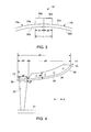
- FIG. 3 illustrates a front view of a connection portion C of the turbine 1.
- FIG. 3 illustrates a first arc-shaped segment 11a connected to a second arc-shaped segment 11b.
- the flange 36b at one end of the first arc-shaped segment 11a is connected to the flange 36a at an end of the second arc-shaped segment 11b.
- the flange 36b has a width d1, and the flange 36a has a width d2.
- the width d1 is the same as the width d2.
- the flanges 36a and 36b have different widths.
- connection region C extends along the length of the arc-shaped segments 11a and 11b, and according to an embodiment of the present invention, the connection region C includes both a first portion from which the flanges 36a and 36b extend, and a second portion adjacent to the front rims 32a and 32b of the arc-shaped segments 11a and 11b from which the flanges 36b and 36a do not protrude.
- FIG. 4 illustrates a side cross-section view of a portion of the turbine 1.
- the outer surface 31 of the arc-shaped segment 11 has a length d3 in a front-to-rear direction X.
- the flange 36 extends from the outer surface 31 along a length d4 of the arc-shaped segment 11.
- the length d4 is less than the entire length d3 of the outer surface 31, so that a region R of the outer surface 31 having a length d5 does not include the flange 36.
- the region R is aligned with the flange 36 in a front-to-rear direction. In other words, the region R having a length d5 lies within the connection region C illustrated in FIG. 3 .
- the region R has an annular shape that encircles the turbine 1.
- the region R corresponding to the length d5 extends around the entire turbine 1, as illustrated in FIG. 1 .
- the region R has a width d7 which corresponds to a width of the arc-shaped segment 11 without the flange 36.
- the portion of the arc-shaped segment 11 that includes the flange 36 has a width d8 that is greater than the width d7.
- FIG. 4 illustrates the region R having no protrusions, such as flanges, ribs, or mounting supports. Consequently, the thermal response of the region R is fast relative to the thermal response of the portion of the arc-shaped segment 11 including the flange 36.
- the region R includes one or more protrusions, such as mounting supports, but the protrusions have a small effect on the thermal response of the region R, and the protrusions have a width d7 less than the width d8 of the portion of the arc-shaped segment 11 including the flange 36.
- the region R corresponds to a stage of buckets 22 of the rotor 20, and the length d5 may be greater than a length of the bucket 22.
- the thermal response of the region R is relatively fast and even, as compared to the portion of the casing 10 having the flanges 36. Consequently, the portion of the casing 10 including the region R maintains a substantially circular shape and rubbing of the buckets 22 against the casing 10 is avoided.
- buckets 22 are arranged around the shaft 21 in an annular manner, and each annular arrangement of buckets 22 makes up part of a stage.
- the stage may also include stationary vanes to form nozzles with direct fluid onto the buckets at predetermined angles. The vanes are omitted from FIG. 4 for clarity.
- the turbine 1 may include any number of stages.
- FIGS. 5 and 6 illustrate comparative thermal responses of annular portions of a turbine 1 having four affixing protrusions 12 at 0 degrees, 90 degrees, 180 degrees, and 270 degrees, and a turbine 1 having no affixing protrusions in the annular portion, respectively.
- T1 represents a time after start-up and before the turbine 1 is at normal operating temperature.
- T2 represents a time when the turbine is at the normal operating temperature.
- T3 represents a time after a shut-down of the turbine 1 has been initiated, but before the temperature of the turbine has cooled to a non-heated state.
- FIG. 5 illustrates the thermal response of the annular portion of the turbine 1 having the affixing protrusions 12.
- the portions of the turbine 1 having the affixing protrusions 12 are heating up slower than the portions of the turbine 1 that do not include the affixing protrusions 12.
- the casing 10 of the turbine 1 warps, as illustrated by the protruding and recessed portions of the line representing T1.
- a physical result of the unequal heating illustrated by the line T1 of FIG. 5 is that the casing 10 becomes misshapen, and parts of the casing 10 bend outward and parts bend inward, resulting in rubbing of the buckets 22 against the casing 10.
- the casing 10 has expanded to have a substantially rounded shape.
- the portions of the casing 10 having the affixing protrusions 12 cool slower than the portions of the casing 10 that do not have the affixing protrusions 12. Consequently, the casing 10 becomes misshapen and out-of-round, as discussed above.
- FIG. 6 illustrates the thermal response of the annular portion of the turbine 1 that does not have the affixing protrusions 12.
- the casing 10 expands consistently around the entire annular portion, and the annular portion retains a round shape.
- the annular portion of the casing 10 that does not have the affixing protrusions 12 cools consistently, maintaining a substantially round shape. Because the casing 10 maintains a round shape during heating and cooling, clearances between tips of the buckets 22 and the inside surface of the casing 10 may be designed to be smaller than a turbine 1 having affixing protrusions 12 extending an entire length of the turbine, and the smaller clearances result in greater efficiency of the turbine 1.
- FIG. 7 illustrates a side cross-sectional view of a double-wall casing of the turbine 1.
- the turbine 1 includes an outer shell 71 and an inner shell 72.
- the inner shell 72 corresponds to the casing 10 of FIG. 1 , and includes the affixing protrusions 12 to connect segments of the inner shell 72 together, as illustrated in FIGS. 1-4 .
- the inner shell 72 includes a sloped portion and a plurality of cylindrical portions 74 at a rear end of the turbine 1.
- the cylindrical portions 74 include flanges 76.
- a cylindrical portion 75 between the cylindrical portions 74 does not include a flange 76, and a space 77 is located between the flanges 76.
- each of the cylindrical portions 74 and 75 includes flanges 76.
- each of the cylindrical portions 74 and 75 is formed as a single body without segments and without flanges 76.
- the outer shell 71 includes supports 73 to support the inner shell 72, while also allowing the inner shell 72 to expand and contract according to the thermal response characteristics of the inner shell 72.
- the supports 73 have an annular shape to encircle the inner shell 72 to provide an air-tight seal to prevent the escape of heated fluid from the turbine 1.
- An annular seal 78 is located at a rear-most portion of the affixing protrusion to further seal the turbine 1.
- the affixing protrusion 12 extends outward to the outer shell 71 and no annular seal 78 is provided.
Landscapes
- Engineering & Computer Science (AREA)
- Mechanical Engineering (AREA)
- General Engineering & Computer Science (AREA)
- Turbine Rotor Nozzle Sealing (AREA)
Abstract
Description
- The subject matter disclosed herein relates to a turbine. In particular, the subject matter disclosed herein relates to a turbine having an unbolted portion.
- A turbine includes a rotor and a casing surrounding the rotor. A fluid, such as gas, air, or liquid, passes through blades of the rotor to drive a shaft of the turbine. The turbine is designed such that during operation, a clearance exists between the casing and blades, or buckets, of the rotor to prevent rubbing of the buckets against the casing. The clearance is maintained as small as possible to prevent fluid from passing around the outside of the buckets. Instead, the fluid is directed at the buckets of the turbine and between the buckets to allow the turbine to function efficiently.
- When the turbine is heated and cooled, the components of the turbine, including the casing, expand and contract according to their thermal response characteristics. If the thermal response of the casing is too slow or uneven around the buckets of the rotor, the buckets rub against the casing. In particular, during start-up, before the casing has been heated and expanded sufficiently, the clearance is small, and uneven expansion of the casing results in rubbing of the buckets against the casing. Since the rubbing of the buckets against the casing leads to loss of material from the bucket tips, the rubbing leads to an increase in the clearance between the casing and the bucket tips, deteriorating performance of the turbine.
- According to one aspect of the invention, a turbine includes a casing having a plurality of arc-shaped segments to together form a substantially circular cross-section shape of the casing, the casing having a front rim to define a front opening and a rear rim to define a rear opening, and the plurality of arc-shaped segments extending in a front-to-rear direction between the front rim and the rear rim; and an affixing protrusion extending radially from an outer surface of the casing at each junction of the plurality of arc-shaped segments to affix adjacent arc-shaped segments to each other. The casing includes an annular region on the outer surface of the casing having no affixing protrusion, the annular region having a thickness from an inside surface to the outside surface less than a thickness of the casing at the affixing protrusion from the inside surface to the outside surface.
- According to another aspect of the invention, a turbine casing comprises a plurality of arc-shaped segments, each arc-shaped segment having a front rim at a front end, a rear rim at a rear end, and a flange at each side end to connect to a flange of an adjacent arc-shaped segment from among the plurality of arc-shaped segments, the flange extending outward from an outer surface of each arc-shaped segment and extending along the outer surface in a front-to-rear direction, each arc-shaped segment having a portion of the outer surface that is co-linear with the flange in a front-to-rear direction that does not include the flange, the portion that does not include the flange having a width from an inner surface of the arc-shaped segment to the outer surface of the arc-shaped segment that is less than a width of the arc-shaped segment at the flange from the inner surface of the arc-shaped segment to the outer surface of the arc-shaped segment.
- These and other advantages and features will become more apparent from the following description taken in conjunction with the drawings.
- The subject matter, which is regarded as the invention, is particularly pointed out and distinctly claimed in the claims at the conclusion of the specification. The foregoing and other features, and advantages of the invention are apparent from the following detailed description taken in conjunction with the accompanying drawings in which:
-
FIG. 1 is a turbine. -
FIG. 2 is an arc-segment of the turbine. -
FIG. 3 is a front plan view of a connection portion of the turbine casing. -
FIG. 4 is a side cross-section view of the connection portion of the casing. -
FIG. 5 is a diagram of casing deformation when flanges extend along the entire connection portion of the casing. -
FIG. 6 is a diagram of casing deformation when flanges extend only part-way along the length of the casing. -
FIG. 7 is a cross-section view of a double-wall casing of a turbine. - The detailed description explains embodiments of the invention, together with advantages and features, by way of example with reference to the drawings.
-
FIG. 1 illustrates a turbine 1 according to one embodiment. The turbine 1 comprisescasing 10 made up of a plurality ofsegments segments 11a-11d as viewed from an intake end of the turbine 1. In addition, thesegments 11a-11d are referred to throughout the specification and claims as arc-shaped segments. - Affixing
protrusions 12 protrude from thecasing 10 of the turbine 1. The affixingprotrusions 12 affix the arc-shaped segments 11a-11d to adjacent arc-shaped segments protrusions 12 extend only part-way along a length of the outer surface of thecasing 10. - The turbine 1 further includes a
rotor 20 having ashaft 21 and blades, or buckets, 22 extending from theshaft 21. An annular region R of thecasing 10 encircles a portion of thecasing 10 corresponding to the stage ofbuckets 22, and the annular region R does not include any affixingprotrusions 12. Additional elements of the turbine 1, such as nozzles and stationary airfoils, are omitted for clarity in describing the present embodiment. - Although
FIG. 1 illustrates a turbine 1 comprising four arc-shaped segments 11a-11d, in alternative embodiments the turbine comprises two, three, or more than four connected arc-shaped segments. -
FIG. 2 illustrates one of the arc-shaped segments 11 of thecasing 10. Each arc-shaped segment 11 includes anouter surface 31, aninner surface 38, afront rim 32, arear rim 33, andside edges Flanges outer surface 31 of thesegment 11. Theflanges opposing side edges shaped segments 11. When all of the arc-shaped segments 11 of the turbine 1 are connected by affixingadjacent flanges 36 to each other, the arc-shaped segments 11 form the turbine 1 having a circular cross-sectional shape. - The
flanges bolt holes 39 to have bolts inserted to affix theflanges shaped segments 11. According to alternative embodiments,adjacent flanges 36 are connected to each other by clamps, welds, or other fixing devices. - The
flanges outer surface 31 of the arc-shaped segment 11 in a front-to-rear direction 11. However, a portion of theouter surface 31 of the arc-shaped segment 11 that is in-line with theflanges FIG. 2 , no flange protrudes radially from theouter surface 31 of the arc-shaped segment 11 at an area adjacent to thefront rim 32 of the arc-shaped segment 11 that is in-line with theflange 36a in a front-to-rear direction X. -
FIG. 3 illustrates a front view of a connection portion C of the turbine 1.FIG. 3 illustrates a first arc-shaped segment 11a connected to a second arc-shaped segment 11b. Theflange 36b at one end of the first arc-shaped segment 11a is connected to theflange 36a at an end of the second arc-shaped segment 11b. Theflange 36b has a width d1, and theflange 36a has a width d2. According to the present embodiment, the width d1 is the same as the width d2. However, in alternative embodiments, theflanges - A combined area of the
outer surface 31a of the first arc-shaped segment 11a and an area of theouter surface 31b of the second arc-shaped segment 11b define a connection region C of thecasing 10. The connection region C extends along the length of the arc-shaped segments flanges front rims shaped segments flanges -
FIG. 4 illustrates a side cross-section view of a portion of the turbine 1. Theouter surface 31 of the arc-shaped segment 11 has a length d3 in a front-to-rear direction X. Theflange 36 extends from theouter surface 31 along a length d4 of the arc-shaped segment 11. The length d4 is less than the entire length d3 of theouter surface 31, so that a region R of theouter surface 31 having a length d5 does not include theflange 36. The region R is aligned with theflange 36 in a front-to-rear direction. In other words, the region R having a length d5 lies within the connection region C illustrated inFIG. 3 . In addition, the region R has an annular shape that encircles the turbine 1. In other words, while a cross-section of only one arc-shapedsegment 11 is illustrated inFIG. 4 , the region R corresponding to the length d5 extends around the entire turbine 1, as illustrated inFIG. 1 . - The region R has a width d7 which corresponds to a width of the arc-shaped
segment 11 without theflange 36. The portion of the arc-shapedsegment 11 that includes theflange 36 has a width d8 that is greater than the width d7.FIG. 4 illustrates the region R having no protrusions, such as flanges, ribs, or mounting supports. Consequently, the thermal response of the region R is fast relative to the thermal response of the portion of the arc-shapedsegment 11 including theflange 36. According to alternative embodiments, the region R includes one or more protrusions, such as mounting supports, but the protrusions have a small effect on the thermal response of the region R, and the protrusions have a width d7 less than the width d8 of the portion of the arc-shapedsegment 11 including theflange 36. - The region R corresponds to a stage of
buckets 22 of therotor 20, and the length d5 may be greater than a length of thebucket 22. When the region R heats up and cools down during operation of the turbine 1, the thermal response of the region R is relatively fast and even, as compared to the portion of thecasing 10 having theflanges 36. Consequently, the portion of thecasing 10 including the region R maintains a substantially circular shape and rubbing of thebuckets 22 against thecasing 10 is avoided. - Although only one
bucket 22 is illustrated inFIG. 4 for purposes of description, it is understood thatbuckets 22 are arranged around theshaft 21 in an annular manner, and each annular arrangement ofbuckets 22 makes up part of a stage. The stage may also include stationary vanes to form nozzles with direct fluid onto the buckets at predetermined angles. The vanes are omitted fromFIG. 4 for clarity. In addition, while only one stage ofbuckets 22 is illustrated inFIG. 4 for clarity, the turbine 1 may include any number of stages. - According to the present embodiment, the region R is a portion of the
outer surface 31 of the arc-shapedsegment 11 that is adjacent to thefront rim 32 in the front-to-rear direction X. However, according to alternative embodiments, the region R may be located adjacent to therear rim 33 of the arc-shapedsegment 11, or at any location between thefront rim 32 and therear rim 33 that corresponds to a stage ofbuckets 22. In addition, a plurality of regions R may be located on the arc-shapedsegment 11, such as adjacent to both thefront rim 32 and therear rim 33. -
FIGS. 5 and 6 illustrate comparative thermal responses of annular portions of a turbine 1 having four affixingprotrusions 12 at 0 degrees, 90 degrees, 180 degrees, and 270 degrees, and a turbine 1 having no affixing protrusions in the annular portion, respectively. T1 represents a time after start-up and before the turbine 1 is at normal operating temperature. T2 represents a time when the turbine is at the normal operating temperature. T3 represents a time after a shut-down of the turbine 1 has been initiated, but before the temperature of the turbine has cooled to a non-heated state. -
FIG. 5 illustrates the thermal response of the annular portion of the turbine 1 having the affixingprotrusions 12. At time T1, the portions of the turbine 1 having the affixingprotrusions 12 are heating up slower than the portions of the turbine 1 that do not include the affixingprotrusions 12. As a result, thecasing 10 of the turbine 1 warps, as illustrated by the protruding and recessed portions of the line representing T1. A physical result of the unequal heating illustrated by the line T1 ofFIG. 5 is that thecasing 10 becomes misshapen, and parts of thecasing 10 bend outward and parts bend inward, resulting in rubbing of thebuckets 22 against thecasing 10. - At time T2, the
casing 10 has expanded to have a substantially rounded shape. At time T3, the portions of thecasing 10 having the affixingprotrusions 12 cool slower than the portions of thecasing 10 that do not have the affixingprotrusions 12. Consequently, thecasing 10 becomes misshapen and out-of-round, as discussed above. -
FIG. 6 illustrates the thermal response of the annular portion of the turbine 1 that does not have the affixingprotrusions 12. At time T1, thecasing 10 expands consistently around the entire annular portion, and the annular portion retains a round shape. Similarly, at time T3, after the shut-down has been initiated, the annular portion of thecasing 10 that does not have the affixingprotrusions 12 cools consistently, maintaining a substantially round shape. Because thecasing 10 maintains a round shape during heating and cooling, clearances between tips of thebuckets 22 and the inside surface of thecasing 10 may be designed to be smaller than a turbine 1 having affixingprotrusions 12 extending an entire length of the turbine, and the smaller clearances result in greater efficiency of the turbine 1. -
FIG. 7 illustrates a side cross-sectional view of a double-wall casing of the turbine 1. The turbine 1 includes anouter shell 71 and aninner shell 72. Theinner shell 72 corresponds to thecasing 10 ofFIG. 1 , and includes the affixingprotrusions 12 to connect segments of theinner shell 72 together, as illustrated inFIGS. 1-4 . - The
inner shell 72 includes a sloped portion and a plurality ofcylindrical portions 74 at a rear end of the turbine 1. Thecylindrical portions 74 includeflanges 76. Acylindrical portion 75 between thecylindrical portions 74 does not include aflange 76, and aspace 77 is located between theflanges 76. According to alternative embodiments, each of thecylindrical portions flanges 76. In yet other embodiments, each of thecylindrical portions flanges 76. - The
outer shell 71 includessupports 73 to support theinner shell 72, while also allowing theinner shell 72 to expand and contract according to the thermal response characteristics of theinner shell 72. The supports 73 have an annular shape to encircle theinner shell 72 to provide an air-tight seal to prevent the escape of heated fluid from the turbine 1. - An
annular seal 78 is located at a rear-most portion of the affixing protrusion to further seal the turbine 1. According to alternative embodiments, the affixingprotrusion 12 extends outward to theouter shell 71 and noannular seal 78 is provided. - While the invention has been described in detail in connection with only a limited number of embodiments, it should be readily understood that the invention is not limited to such disclosed embodiments. Rather, the invention can be modified to incorporate any number of variations, alterations, substitutions or equivalent arrangements not heretofore described, but which are commensurate with the spirit and scope of the invention. Additionally, while various embodiments of the invention have been described, it is to be understood that aspects of the invention may include only some of the described embodiments. Accordingly, the invention is not to be seen as limited by the foregoing description, but is only limited by the scope of the appended claims.
Claims (15)
- A turbine, comprising:a casing (10) having a plurality of arc-shaped segments (11a,11b,11c,11d) to together form a substantially circular cross-section shape of the casing, the casing having a front rim (32) to define a front opening and a rear rim (33) to define a rear opening, and the plurality of arc-shaped segments extending in a front-to-rear direction between the front rim and the rear rim; andan affixing protrusion (12) extending radially from an outer surface (31) of the casing at each junction of the plurality of arc-shaped segments to affix adjacent arc-shaped segments (11) to each other,wherein the casing includes an annular region (R) on the outer surface (31) of the casing having no affixing protrusion, the annular region having a thickness from an inside surface (38) to the outside surface (31) less than a thickness of the casing (10) at the affixing protrusion (12) from the inside surface to the outside surface.
- The turbine of claim 1, wherein the annular region is located adjacent to the front rim of the casing.
- The turbine of claim 1 or claim 2, wherein the affixing protrusion extends in the front-to-rear direction on the outer surface of the casing from the rear rim of the casing to the annular region.
- The turbine of any preceding claim, wherein the affixing protrusion includes flanges radially extending from adjacent arc-shaped segments from among the plurality of arc-shaped segments.
- The turbine of any preceding claim, further comprising:a rotor comprising a plurality of annular stages of buckets,wherein the annular region of the casing corresponds to a location of at least one of the annular stages of buckets.
- The turbine of claim 5, wherein the annular region of the casing has a width greater than a width of bucket tips of the at least one annular stage of buckets.
- The turbine of claim 5 or claim 6, wherein the annular region of the casing extends at least from the front rim of the casing to a rear side of the at least one annular stage of buckets.
- The turbine of any preceding claim, wherein the casing comprises:an inner shell including the plurality of arc-shaped segments; andan outer shell surrounding the inner shell to provide an air-tight seal around the inner shell.
- A turbine casing, comprising:a plurality of arc-shaped segments, each arc-shaped segment having a front rim at a front end, a rear rim at a rear end, and a flange at each side end to connect to a flange of an adjacent arc-shaped segment from among the plurality of arc-shaped segments, the flange extending outward from an outer surface of each arc-shaped segment and extending along the outer surface in a front-to-rear direction, each arc-shaped segment having a portion of the outer surface that is co-linear with the flange in the front-to-rear direction that does not include the flange, the portion of each arc-shaped segment that does not include the flange having a width from an inner surface of the arc-shaped segment to the outer surface of the arc-shaped segment that is less than a width of the arc-shaped segment at the flange from the inner surface of the arc-shaped segment to the outer surface of the arc-shaped segment.
- The turbine casing of claim 9, wherein the portion of the outer surface of each of the plurality of arc-shaped segments that does not include the flange is located adjacent to the front rim.
- The turbine casing of claim 9 or claim 10, wherein the flange extends from the rear rim to the portion of the outer surface that does not include the flange.
- The turbine casing of any one of claims 9 to 11, wherein the flange extends contiguously from the rear rim to the portion of the outer surface that does not include the flange
- The turbine casing of any one of claims 9 to 12, wherein the portion of each of the plurality of arc-shaped segments that does not include the flange has a width corresponding to a predetermined width of a turbine bucket.
- The turbine casing of any one of claims 9 to 13, wherein the front rim has a diameter smaller than the rear rim.
- The turbine casing of claim 14, wherein each of the plurality of arc-shaped segments is curved between the front rim and the rear rim.
Applications Claiming Priority (1)
| Application Number | Priority Date | Filing Date | Title |
|---|---|---|---|
| US13/343,322 US9127568B2 (en) | 2012-01-04 | 2012-01-04 | Turbine casing |
Publications (3)
| Publication Number | Publication Date |
|---|---|
| EP2613020A2 true EP2613020A2 (en) | 2013-07-10 |
| EP2613020A3 EP2613020A3 (en) | 2017-05-17 |
| EP2613020B1 EP2613020B1 (en) | 2021-03-03 |
Family
ID=47603059
Family Applications (1)
| Application Number | Title | Priority Date | Filing Date |
|---|---|---|---|
| EP12198420.7A Active EP2613020B1 (en) | 2012-01-04 | 2012-12-20 | Turbine casing |
Country Status (5)
| Country | Link |
|---|---|
| US (1) | US9127568B2 (en) |
| EP (1) | EP2613020B1 (en) |
| JP (1) | JP6154608B2 (en) |
| CN (1) | CN103195509B (en) |
| RU (1) | RU2603885C2 (en) |
Families Citing this family (4)
| Publication number | Priority date | Publication date | Assignee | Title |
|---|---|---|---|---|
| US9127568B2 (en) * | 2012-01-04 | 2015-09-08 | General Electric Company | Turbine casing |
| FR3008912B1 (en) * | 2013-07-29 | 2017-12-15 | Snecma | TURBOMACHINE CASING AND METHOD OF MANUFACTURE |
| FR3051840B1 (en) * | 2016-05-31 | 2020-01-10 | Safran Aircraft Engines | INTERMEDIATE CRANKCASE OF TURBOMACHINE, EQUIPPED WITH A SEALING PART WITH ARM / CRANK INTERFACE |
| FR3098547B1 (en) * | 2019-07-08 | 2022-04-29 | Safran Aircraft Engines | HOLDING ASSEMBLY FOR A GEAR TRAIN IN A TURBOMACHINE |
Family Cites Families (25)
| Publication number | Priority date | Publication date | Assignee | Title |
|---|---|---|---|---|
| US1957699A (en) | 1930-04-25 | 1934-05-08 | Allis Chalmers Mfg Co | Flange connection |
| US1957700A (en) | 1931-04-16 | 1934-05-08 | Allis Chalmers Mfg Co | Flange connection |
| US4492517A (en) * | 1983-01-06 | 1985-01-08 | General Electric Company | Segmented inlet nozzle for gas turbine, and methods of installation |
| US4840026A (en) * | 1988-02-24 | 1989-06-20 | The United States Of America As Represented By The Secretary Of The Air Force | Band clamp apparatus |
| US5133641A (en) | 1991-02-01 | 1992-07-28 | Westinghouse Electric Corp. | Support arrangement for optimizing a low pressure steam turbine inner cylinder structural performance |
| US5320486A (en) * | 1993-01-21 | 1994-06-14 | General Electric Company | Apparatus for positioning compressor liner segments |
| US5593276A (en) * | 1995-06-06 | 1997-01-14 | General Electric Company | Turbine shroud hanger |
| US5605438A (en) * | 1995-12-29 | 1997-02-25 | General Electric Co. | Casing distortion control for rotating machinery |
| DE69824925T2 (en) * | 1997-09-17 | 2005-08-25 | Mitsubishi Heavy Industries, Ltd. | Leitschaufelpaar |
| US5961278A (en) * | 1997-12-17 | 1999-10-05 | Pratt & Whitney Canada Inc. | Housing for turbine assembly |
| RU2135782C1 (en) * | 1998-04-24 | 1999-08-27 | Государственное унитарное предприятие Тушинское машиностроительное конструкторское бюро "Союз" | Gas-turbine plant |
| JP3697093B2 (en) * | 1998-12-08 | 2005-09-21 | 三菱重工業株式会社 | Gas turbine combustor |
| US6352404B1 (en) * | 2000-02-18 | 2002-03-05 | General Electric Company | Thermal control passages for horizontal split-line flanges of gas turbine engine casings |
| DE10051223A1 (en) * | 2000-10-16 | 2002-04-25 | Alstom Switzerland Ltd | Connectable stator elements |
| US7037065B2 (en) | 2002-03-20 | 2006-05-02 | Alstom Technology Ltd | Flange bolt for turbines |
| US7419121B2 (en) * | 2004-12-09 | 2008-09-02 | Honeywell International Inc. | Integrated mount duct for use with airborne auxiliary power units and other turbomachines |
| US20060145001A1 (en) * | 2004-12-30 | 2006-07-06 | Smith Matthew C | Fan cowl door elimination |
| US8292571B2 (en) * | 2007-10-12 | 2012-10-23 | General Electric Company | Apparatus and method for clearance control of turbine blade tip |
| US8021109B2 (en) * | 2008-01-22 | 2011-09-20 | General Electric Company | Turbine casing with false flange |
| US8128353B2 (en) * | 2008-09-30 | 2012-03-06 | General Electric Company | Method and apparatus for matching the thermal mass and stiffness of bolted split rings |
| US8092168B2 (en) * | 2009-04-10 | 2012-01-10 | General Electric Company | Patch plug repair of a compressor case stator ring hook, near the horizontal joint |
| US8197191B2 (en) * | 2009-04-14 | 2012-06-12 | Rohr, Inc. | Inlet section of an aircraft engine nacelle |
| JP2012112359A (en) * | 2010-11-26 | 2012-06-14 | Toshiba Corp | Bearing stand cover of axial-flow exhaust turbine and axial-flow exhaust turbine |
| US8668450B2 (en) * | 2010-12-29 | 2014-03-11 | General Electric Company | Removable upper steam guide segment for steam turbine |
| US9127568B2 (en) * | 2012-01-04 | 2015-09-08 | General Electric Company | Turbine casing |
-
2012
- 2012-01-04 US US13/343,322 patent/US9127568B2/en active Active
- 2012-12-20 EP EP12198420.7A patent/EP2613020B1/en active Active
- 2012-12-25 JP JP2012280450A patent/JP6154608B2/en active Active
- 2012-12-27 RU RU2012158305/06A patent/RU2603885C2/en not_active IP Right Cessation
-
2013
- 2013-01-04 CN CN201310001380.6A patent/CN103195509B/en active Active
Non-Patent Citations (1)
| Title |
|---|
| None |
Also Published As
| Publication number | Publication date |
|---|---|
| US20130170978A1 (en) | 2013-07-04 |
| EP2613020A3 (en) | 2017-05-17 |
| RU2603885C2 (en) | 2016-12-10 |
| CN103195509A (en) | 2013-07-10 |
| JP6154608B2 (en) | 2017-06-28 |
| RU2012158305A (en) | 2014-07-10 |
| CN103195509B (en) | 2016-02-17 |
| EP2613020B1 (en) | 2021-03-03 |
| US9127568B2 (en) | 2015-09-08 |
| JP2013139794A (en) | 2013-07-18 |
Similar Documents
| Publication | Publication Date | Title |
|---|---|---|
| JP5628190B2 (en) | Ring segment positioning member | |
| JP5717904B1 (en) | Stator blade, gas turbine, split ring, stator blade remodeling method, and split ring remodeling method | |
| US10612397B2 (en) | Insert assembly, airfoil, gas turbine, and airfoil manufacturing method | |
| US6514041B1 (en) | Carrier for guide vane and heat shield segment | |
| EP2546471B1 (en) | Tip clearance control for turbine blades | |
| JP5995958B2 (en) | Sealing device for turbomachine turbine nozzle | |
| CN101852097B (en) | Systems, methods, and apparatus for passive purge flow control in a turbine | |
| JP6399894B2 (en) | Exhaust device and gas turbine | |
| US8662823B2 (en) | Flow path for steam turbine outer casing and flow barrier apparatus | |
| EP2613020B1 (en) | Turbine casing | |
| EP2636851B1 (en) | Turbine assembly and method for supporting turbine components | |
| CN109184808A (en) | Segmented turbine guider link construction, installation method and gas-turbine unit | |
| RU2645892C2 (en) | Turbine | |
| US9382807B2 (en) | Non-axisymmetric rim cavity features to improve sealing efficiencies | |
| EP2514942B1 (en) | Vehicle heat- exchange module | |
| JP2022502599A (en) | Circular assembly for turbomachinery | |
| US12372012B2 (en) | Rotating-machine casing support structure and rotating machine | |
| JP2018159301A (en) | Rotary machine | |
| JP2005194914A (en) | Seal structure and turbine nozzle | |
| JP2010001841A (en) | Moving blade and gas turbine |
Legal Events
| Date | Code | Title | Description |
|---|---|---|---|
| PUAI | Public reference made under article 153(3) epc to a published international application that has entered the european phase |
Free format text: ORIGINAL CODE: 0009012 |
|
| AK | Designated contracting states |
Kind code of ref document: A2 Designated state(s): AL AT BE BG CH CY CZ DE DK EE ES FI FR GB GR HR HU IE IS IT LI LT LU LV MC MK MT NL NO PL PT RO RS SE SI SK SM TR |
|
| AX | Request for extension of the european patent |
Extension state: BA ME |
|
| PUAL | Search report despatched |
Free format text: ORIGINAL CODE: 0009013 |
|
| AK | Designated contracting states |
Kind code of ref document: A3 Designated state(s): AL AT BE BG CH CY CZ DE DK EE ES FI FR GB GR HR HU IE IS IT LI LT LU LV MC MK MT NL NO PL PT RO RS SE SI SK SM TR |
|
| AX | Request for extension of the european patent |
Extension state: BA ME |
|
| RIC1 | Information provided on ipc code assigned before grant |
Ipc: F01D 25/24 20060101AFI20170410BHEP Ipc: F01D 25/26 20060101ALI20170410BHEP Ipc: F02K 3/06 20060101ALI20170410BHEP |
|
| STAA | Information on the status of an ep patent application or granted ep patent |
Free format text: STATUS: REQUEST FOR EXAMINATION WAS MADE |
|
| 17P | Request for examination filed |
Effective date: 20171117 |
|
| RBV | Designated contracting states (corrected) |
Designated state(s): AL AT BE BG CH CY CZ DE DK EE ES FI FR GB GR HR HU IE IS IT LI LT LU LV MC MK MT NL NO PL PT RO RS SE SI SK SM TR |
|
| STAA | Information on the status of an ep patent application or granted ep patent |
Free format text: STATUS: EXAMINATION IS IN PROGRESS |
|
| 17Q | First examination report despatched |
Effective date: 20200403 |
|
| GRAP | Despatch of communication of intention to grant a patent |
Free format text: ORIGINAL CODE: EPIDOSNIGR1 |
|
| STAA | Information on the status of an ep patent application or granted ep patent |
Free format text: STATUS: GRANT OF PATENT IS INTENDED |
|
| INTG | Intention to grant announced |
Effective date: 20201009 |
|
| GRAS | Grant fee paid |
Free format text: ORIGINAL CODE: EPIDOSNIGR3 |
|
| GRAA | (expected) grant |
Free format text: ORIGINAL CODE: 0009210 |
|
| STAA | Information on the status of an ep patent application or granted ep patent |
Free format text: STATUS: THE PATENT HAS BEEN GRANTED |
|
| AK | Designated contracting states |
Kind code of ref document: B1 Designated state(s): AL AT BE BG CH CY CZ DE DK EE ES FI FR GB GR HR HU IE IS IT LI LT LU LV MC MK MT NL NO PL PT RO RS SE SI SK SM TR |
|
| REG | Reference to a national code |
Ref country code: GB Ref legal event code: FG4D |
|
| REG | Reference to a national code |
Ref country code: AT Ref legal event code: REF Ref document number: 1367428 Country of ref document: AT Kind code of ref document: T Effective date: 20210315 Ref country code: CH Ref legal event code: EP |
|
| REG | Reference to a national code |
Ref country code: DE Ref legal event code: R096 Ref document number: 602012074596 Country of ref document: DE |
|
| REG | Reference to a national code |
Ref country code: IE Ref legal event code: FG4D |
|
| REG | Reference to a national code |
Ref country code: LT Ref legal event code: MG9D |
|
| PG25 | Lapsed in a contracting state [announced via postgrant information from national office to epo] |
Ref country code: NO Free format text: LAPSE BECAUSE OF FAILURE TO SUBMIT A TRANSLATION OF THE DESCRIPTION OR TO PAY THE FEE WITHIN THE PRESCRIBED TIME-LIMIT Effective date: 20210603 Ref country code: BG Free format text: LAPSE BECAUSE OF FAILURE TO SUBMIT A TRANSLATION OF THE DESCRIPTION OR TO PAY THE FEE WITHIN THE PRESCRIBED TIME-LIMIT Effective date: 20210603 Ref country code: FI Free format text: LAPSE BECAUSE OF FAILURE TO SUBMIT A TRANSLATION OF THE DESCRIPTION OR TO PAY THE FEE WITHIN THE PRESCRIBED TIME-LIMIT Effective date: 20210303 Ref country code: HR Free format text: LAPSE BECAUSE OF FAILURE TO SUBMIT A TRANSLATION OF THE DESCRIPTION OR TO PAY THE FEE WITHIN THE PRESCRIBED TIME-LIMIT Effective date: 20210303 Ref country code: GR Free format text: LAPSE BECAUSE OF FAILURE TO SUBMIT A TRANSLATION OF THE DESCRIPTION OR TO PAY THE FEE WITHIN THE PRESCRIBED TIME-LIMIT Effective date: 20210604 Ref country code: LT Free format text: LAPSE BECAUSE OF FAILURE TO SUBMIT A TRANSLATION OF THE DESCRIPTION OR TO PAY THE FEE WITHIN THE PRESCRIBED TIME-LIMIT Effective date: 20210303 |
|
| REG | Reference to a national code |
Ref country code: NL Ref legal event code: MP Effective date: 20210303 |
|
| REG | Reference to a national code |
Ref country code: AT Ref legal event code: MK05 Ref document number: 1367428 Country of ref document: AT Kind code of ref document: T Effective date: 20210303 |
|
| PG25 | Lapsed in a contracting state [announced via postgrant information from national office to epo] |
Ref country code: RS Free format text: LAPSE BECAUSE OF FAILURE TO SUBMIT A TRANSLATION OF THE DESCRIPTION OR TO PAY THE FEE WITHIN THE PRESCRIBED TIME-LIMIT Effective date: 20210303 Ref country code: LV Free format text: LAPSE BECAUSE OF FAILURE TO SUBMIT A TRANSLATION OF THE DESCRIPTION OR TO PAY THE FEE WITHIN THE PRESCRIBED TIME-LIMIT Effective date: 20210303 Ref country code: PL Free format text: LAPSE BECAUSE OF FAILURE TO SUBMIT A TRANSLATION OF THE DESCRIPTION OR TO PAY THE FEE WITHIN THE PRESCRIBED TIME-LIMIT Effective date: 20210303 Ref country code: SE Free format text: LAPSE BECAUSE OF FAILURE TO SUBMIT A TRANSLATION OF THE DESCRIPTION OR TO PAY THE FEE WITHIN THE PRESCRIBED TIME-LIMIT Effective date: 20210303 |
|
| PG25 | Lapsed in a contracting state [announced via postgrant information from national office to epo] |
Ref country code: NL Free format text: LAPSE BECAUSE OF FAILURE TO SUBMIT A TRANSLATION OF THE DESCRIPTION OR TO PAY THE FEE WITHIN THE PRESCRIBED TIME-LIMIT Effective date: 20210303 |
|
| PG25 | Lapsed in a contracting state [announced via postgrant information from national office to epo] |
Ref country code: EE Free format text: LAPSE BECAUSE OF FAILURE TO SUBMIT A TRANSLATION OF THE DESCRIPTION OR TO PAY THE FEE WITHIN THE PRESCRIBED TIME-LIMIT Effective date: 20210303 Ref country code: CZ Free format text: LAPSE BECAUSE OF FAILURE TO SUBMIT A TRANSLATION OF THE DESCRIPTION OR TO PAY THE FEE WITHIN THE PRESCRIBED TIME-LIMIT Effective date: 20210303 Ref country code: SM Free format text: LAPSE BECAUSE OF FAILURE TO SUBMIT A TRANSLATION OF THE DESCRIPTION OR TO PAY THE FEE WITHIN THE PRESCRIBED TIME-LIMIT Effective date: 20210303 Ref country code: AT Free format text: LAPSE BECAUSE OF FAILURE TO SUBMIT A TRANSLATION OF THE DESCRIPTION OR TO PAY THE FEE WITHIN THE PRESCRIBED TIME-LIMIT Effective date: 20210303 |
|
| PG25 | Lapsed in a contracting state [announced via postgrant information from national office to epo] |
Ref country code: IS Free format text: LAPSE BECAUSE OF FAILURE TO SUBMIT A TRANSLATION OF THE DESCRIPTION OR TO PAY THE FEE WITHIN THE PRESCRIBED TIME-LIMIT Effective date: 20210703 Ref country code: RO Free format text: LAPSE BECAUSE OF FAILURE TO SUBMIT A TRANSLATION OF THE DESCRIPTION OR TO PAY THE FEE WITHIN THE PRESCRIBED TIME-LIMIT Effective date: 20210303 Ref country code: PT Free format text: LAPSE BECAUSE OF FAILURE TO SUBMIT A TRANSLATION OF THE DESCRIPTION OR TO PAY THE FEE WITHIN THE PRESCRIBED TIME-LIMIT Effective date: 20210705 Ref country code: ES Free format text: LAPSE BECAUSE OF FAILURE TO SUBMIT A TRANSLATION OF THE DESCRIPTION OR TO PAY THE FEE WITHIN THE PRESCRIBED TIME-LIMIT Effective date: 20210303 Ref country code: SK Free format text: LAPSE BECAUSE OF FAILURE TO SUBMIT A TRANSLATION OF THE DESCRIPTION OR TO PAY THE FEE WITHIN THE PRESCRIBED TIME-LIMIT Effective date: 20210303 |
|
| REG | Reference to a national code |
Ref country code: DE Ref legal event code: R097 Ref document number: 602012074596 Country of ref document: DE |
|
| PLBE | No opposition filed within time limit |
Free format text: ORIGINAL CODE: 0009261 |
|
| STAA | Information on the status of an ep patent application or granted ep patent |
Free format text: STATUS: NO OPPOSITION FILED WITHIN TIME LIMIT |
|
| PG25 | Lapsed in a contracting state [announced via postgrant information from national office to epo] |
Ref country code: DK Free format text: LAPSE BECAUSE OF FAILURE TO SUBMIT A TRANSLATION OF THE DESCRIPTION OR TO PAY THE FEE WITHIN THE PRESCRIBED TIME-LIMIT Effective date: 20210303 Ref country code: AL Free format text: LAPSE BECAUSE OF FAILURE TO SUBMIT A TRANSLATION OF THE DESCRIPTION OR TO PAY THE FEE WITHIN THE PRESCRIBED TIME-LIMIT Effective date: 20210303 |
|
| 26N | No opposition filed |
Effective date: 20211206 |
|
| PG25 | Lapsed in a contracting state [announced via postgrant information from national office to epo] |
Ref country code: SI Free format text: LAPSE BECAUSE OF FAILURE TO SUBMIT A TRANSLATION OF THE DESCRIPTION OR TO PAY THE FEE WITHIN THE PRESCRIBED TIME-LIMIT Effective date: 20210303 |
|
| PG25 | Lapsed in a contracting state [announced via postgrant information from national office to epo] |
Ref country code: IS Free format text: LAPSE BECAUSE OF FAILURE TO SUBMIT A TRANSLATION OF THE DESCRIPTION OR TO PAY THE FEE WITHIN THE PRESCRIBED TIME-LIMIT Effective date: 20210703 |
|
| PG25 | Lapsed in a contracting state [announced via postgrant information from national office to epo] |
Ref country code: MC Free format text: LAPSE BECAUSE OF FAILURE TO SUBMIT A TRANSLATION OF THE DESCRIPTION OR TO PAY THE FEE WITHIN THE PRESCRIBED TIME-LIMIT Effective date: 20210303 |
|
| REG | Reference to a national code |
Ref country code: CH Ref legal event code: PL |
|
| GBPC | Gb: european patent ceased through non-payment of renewal fee |
Effective date: 20211220 |
|
| REG | Reference to a national code |
Ref country code: BE Ref legal event code: MM Effective date: 20211231 |
|
| PG25 | Lapsed in a contracting state [announced via postgrant information from national office to epo] |
Ref country code: LU Free format text: LAPSE BECAUSE OF NON-PAYMENT OF DUE FEES Effective date: 20211220 Ref country code: IE Free format text: LAPSE BECAUSE OF NON-PAYMENT OF DUE FEES Effective date: 20211220 Ref country code: GB Free format text: LAPSE BECAUSE OF NON-PAYMENT OF DUE FEES Effective date: 20211220 |
|
| PG25 | Lapsed in a contracting state [announced via postgrant information from national office to epo] |
Ref country code: FR Free format text: LAPSE BECAUSE OF NON-PAYMENT OF DUE FEES Effective date: 20211231 Ref country code: BE Free format text: LAPSE BECAUSE OF NON-PAYMENT OF DUE FEES Effective date: 20211231 |
|
| PG25 | Lapsed in a contracting state [announced via postgrant information from national office to epo] |
Ref country code: LI Free format text: LAPSE BECAUSE OF NON-PAYMENT OF DUE FEES Effective date: 20211231 Ref country code: CH Free format text: LAPSE BECAUSE OF NON-PAYMENT OF DUE FEES Effective date: 20211231 |
|
| PG25 | Lapsed in a contracting state [announced via postgrant information from national office to epo] |
Ref country code: HU Free format text: LAPSE BECAUSE OF FAILURE TO SUBMIT A TRANSLATION OF THE DESCRIPTION OR TO PAY THE FEE WITHIN THE PRESCRIBED TIME-LIMIT; INVALID AB INITIO Effective date: 20121220 Ref country code: CY Free format text: LAPSE BECAUSE OF FAILURE TO SUBMIT A TRANSLATION OF THE DESCRIPTION OR TO PAY THE FEE WITHIN THE PRESCRIBED TIME-LIMIT Effective date: 20210303 |
|
| REG | Reference to a national code |
Ref country code: DE Ref legal event code: R081 Ref document number: 602012074596 Country of ref document: DE Owner name: GENERAL ELECTRIC TECHNOLOGY GMBH, CH Free format text: FORMER OWNER: GENERAL ELECTRIC COMPANY, SCHENECTADY, NY, US |
|
| PG25 | Lapsed in a contracting state [announced via postgrant information from national office to epo] |
Ref country code: MK Free format text: LAPSE BECAUSE OF FAILURE TO SUBMIT A TRANSLATION OF THE DESCRIPTION OR TO PAY THE FEE WITHIN THE PRESCRIBED TIME-LIMIT Effective date: 20210303 |
|
| PG25 | Lapsed in a contracting state [announced via postgrant information from national office to epo] |
Ref country code: TR Free format text: LAPSE BECAUSE OF FAILURE TO SUBMIT A TRANSLATION OF THE DESCRIPTION OR TO PAY THE FEE WITHIN THE PRESCRIBED TIME-LIMIT Effective date: 20210303 |
|
| PG25 | Lapsed in a contracting state [announced via postgrant information from national office to epo] |
Ref country code: MT Free format text: LAPSE BECAUSE OF FAILURE TO SUBMIT A TRANSLATION OF THE DESCRIPTION OR TO PAY THE FEE WITHIN THE PRESCRIBED TIME-LIMIT Effective date: 20210303 |
|
| PGFP | Annual fee paid to national office [announced via postgrant information from national office to epo] |
Ref country code: DE Payment date: 20251126 Year of fee payment: 14 |
|
| PGFP | Annual fee paid to national office [announced via postgrant information from national office to epo] |
Ref country code: IT Payment date: 20251119 Year of fee payment: 14 |