EP2613001A2 - Turbine Rotor Rim Seal Axial Retention Assembly - Google Patents
Turbine Rotor Rim Seal Axial Retention Assembly Download PDFInfo
- Publication number
- EP2613001A2 EP2613001A2 EP12199292.9A EP12199292A EP2613001A2 EP 2613001 A2 EP2613001 A2 EP 2613001A2 EP 12199292 A EP12199292 A EP 12199292A EP 2613001 A2 EP2613001 A2 EP 2613001A2
- Authority
- EP
- European Patent Office
- Prior art keywords
- block
- seal
- spacer disk
- rim
- retention
- Prior art date
- Legal status (The legal status is an assumption and is not a legal conclusion. Google has not performed a legal analysis and makes no representation as to the accuracy of the status listed.)
- Granted
Links
Images




Classifications
-
- F—MECHANICAL ENGINEERING; LIGHTING; HEATING; WEAPONS; BLASTING
- F01—MACHINES OR ENGINES IN GENERAL; ENGINE PLANTS IN GENERAL; STEAM ENGINES
- F01D—NON-POSITIVE DISPLACEMENT MACHINES OR ENGINES, e.g. STEAM TURBINES
- F01D5/00—Blades; Blade-carrying members; Heating, heat-insulating, cooling or antivibration means on the blades or the members
- F01D5/30—Fixing blades to rotors; Blade roots ; Blade spacers
- F01D5/32—Locking, e.g. by final locking blades or keys
- F01D5/326—Locking of axial insertion type blades by other means
Definitions
- the present invention relates generally to turbine rotors and, more specifically, to a system for the axial retention of a turbine rotor rim seal mounted on a turbine rotor spacer disk.
- Turbine rotor spacer disks are provided with a plurality of rim seals in the form of arcuate seal segments, which, when installed, form a 360° seal.
- Each seal segment (or, simply, seal or rim seal) is secured to the spacer disk by means of mating dovetail surface features that are configured to enable axial loading of the rim seals onto the spacer disk.
- a retention device for maintaining a first rotary machine component axially loaded onto a second rotary machine component in a fixed axial position
- the retention device comprising a block sized and configured to move between first and second aligned recesses in the first and second rotary machine components, the aligned recesses shaped to prevent rotation of the block, the block having a threaded bore extending therethrough; and an actuator threadably mounted in the bore, such that rotation of the actuator will, in use, move the block from the first aligned recess at least partially into the second aligned recess.
- the invention resides in an axial retention system for a plurality of rim seals axially loaded onto a rotor spacer disk, the axial retention system comprising a shear key adapted to be inserted between an annular circumferential groove in the rotor spacer disk and a radial notch formed in a circumferential end face of the rim seal; and a lock block sized and configured to move between first and second recesses formed, respectively, in the rotor spacer disk and said rim seal when the rim seal is loaded axially onto the rotor spacer disk, the lock block provided with an actuator adapted to move the lock block into a position straddling the first and second recesses.
- the invention resides in an axial retention system for a plurality of rim seals axially loaded onto a rotor spacer disk, the axial retention system comprising for each rim seal except for a finally-installed locker seal, a shear key adapted to be inserted between an annular circumferential groove in the spacer disk and a radial notch formed in an end face of the rim seal; and a back-up stop pin extending from the end face and receivable in a notch formed in an end face of a next-adjacent rim seal.
- the axial retention system for the rotor spacer disk rim seals is made up of three components. As will be explained in further detail below, not all of the components are used with every rim seal. In this regard, it will be appreciated that the rim seals are loaded axially onto the spacer disk. The assembly is done in a sequential manner, and the system as disclosed herein utilizes at least two of the components for all but the finally-installed rim seal. A third component is employed with the finally-installed seal (also referred to as the "locker seal”) to effectively lock the entire array of seals to the spacer disk.
- a rim seal 10 is shown, in schematic form, axially loaded onto the rotor spacer disk 12.
- the rim seal 10 interfaces with adjacent turbine components 14, 16, as is well understood in the art. As illustrated, the loading or installation direction is from right-to-left.
- the three axial retention components in accordance with the exemplary but nonlimiting embodiment, include a shear key 18, a back-up pin 20 and a locker "puck" (also referred to herein as a lock block)22.
- FIGs. 1 and 2 are intended to show the components utilized during installation for convenience and ease of understanding but, for all but one of the rim seals 10 loaded onto the spacer disk 12, only the shear key 18 and back-up pin 20 are utilized.
- the last rim seal or locker seal 10 installed on the spacer disk utilizes the locker puck 22, but not the shear key 18 or back-up pin 20, as further explained below.
- one circumferential end face 24 of the rim seal 10 is formed with a radially-oriented notch 26 adjacent the entry end of the spacer disk slot 27, opening from the bottom surface 28 of a flange portion 30 of the rim seal as well as from the end face 24.
- the notch 26 is otherwise closed in circumferential and axial directions.
- the notch 26 is located to align radially with a discontinuous annular groove 34 formed in the spacer disk 12 upon installation of the rim seal 10 (sometimes referred to herein simply as "the seal 10"). It will be appreciated that the groove 34 and notch 26 may be located further away from the entry end of the disk slot 27 if desired.
- the L-shaped shear key 18 (see also FIG. 5 ) is located in the groove 34 and notch 26 as best seen in FIG. 3 .
- the dimensions and shape of the shear key 18 are such that it can be located in only one orientation, making installation fool-proof. More specifically, the radially outwardly extending leg or stem 36 of the L-shaped shear key is formed with an angled corner 38 that mates with a correspondingly-shaped angled corner 40 of the notch 26.
- the horizontal (or circumferential) leg or base 42 of the L-shaped shear key 18 sits in the groove 34.
- shear key 18 can be located in the groove 34 and notch 26 after the seal 10 is axially loaded onto the spacer disk 12 or, alternatively, the shear key 18 can be located in the groove 34, laterally away from the seal 10 and moved into engagement with the notch 26 after the seal 10 is installed.
- the circumferential end face 24 of the seal 10 is also formed with a blind bore 46 ( FIG. 6 ) at the opposite end of the face 24 from the shear key 18.
- the bore 46 receives the back-up stop pin 20 (cylindrical in the example embodiment) via a press fit, or by other suitable means, leaving a portion of the pin 20 exposed.
- the stop pin 20 prevents axial movement of the rim seal 10 in at least one axial direction, as described further below, thus providing a back-up function in the event that the shear key 18 has been inadvertently omitted during installation of the seal.
- next adjacent seal can be slid axially along its dovetail groove 48 formed in the spacer disk, passing by (and over) the base 42 of the shear key 18 and stopping when the axial stop pin 20 engages within an open notch 50 ( FIGs. 6 , 7 ) formed in the circumferential end face 52 of a next adjacent seal 54.
- the notch wall 56 thus serves as the stop limit for the axial installation movement in one direction of the next adjacent seal, and the next-installed shear key then also precludes any axial movement in both the installation and opposite directions.
- An oblong or oval locker "puck" 22 is shaped and sized to fit in and between vertically-adjacent, recesses 60, 62 formed in the spacer disk 12 and seal 58, respectively. More specifically, the oblong or oval recess 60 is formed in the upper (radially outer) surface 64 of the spacer disk post 66 ( FIG. 8 ). The recess 62 ( FIGs. 10-11 ) is formed in the radially inner surface 68 of the seal flange portion 70, the recesses 60 and 62 vertically (or radially) aligning when the seal 58 is loaded into the spacer disk 12.
- a threaded bore 72 extends vertically or radially through the puck 22 and a threaded adjustment stud or screw 74 extends through the puck 22.
- a bore 76 may be formed in the seal and extends radially outwardly to an access location, where a tool may be inserted.
- the tool is designed to engage a surface feature 78 (e.g., an Allen-wrench recess) formed in the end of the stud or screw 74.
- a surface feature 78 e.g., an Allen-wrench recess
- an elongated bolt 80 ( FIGs. 12, 13 ) with a threaded end 82 may be used to engage the puck 22.
- the bolt 80 will extend through the bore 76 and rotation of the bolt will cause the puck 22 to move axially along the threaded end 82 (and radially relative to the spacer disk) substantially as described above.
- a fail or weak point in the form of groove 84 may be provided in the bolt shank 86 adjacent the threaded end 82 to facilitate breaking and removal of the bolt shank after installation if desired.
- a frangible shim 88 is integrally attached to the lower part of the threaded shank 74 as shown in FIG. 14 , in conjunction with an extended receptacle portion 90 provided in the disk, radially inward of the recess 60. This allows the shank 74 to be punched radially into the receptacle portion 90, causing the puck 22 to fall back into the rotor disk, thus providing an alternative technique for releasing the rim seal for axial movement.
- the locker puck 22 may be utilized in the three-component system as described above, or, alternatively, as a stand-alone retention device used in connection with any one or all of the rim seals. Moreover, the locker puck 22 can be employed in any other application where retention of one component in a slot formed in a second component is desired.
Landscapes
- Engineering & Computer Science (AREA)
- Mechanical Engineering (AREA)
- General Engineering & Computer Science (AREA)
- Turbine Rotor Nozzle Sealing (AREA)
- Gasket Seals (AREA)
- Mechanical Sealing (AREA)
Abstract
Description
- The present invention relates generally to turbine rotors and, more specifically, to a system for the axial retention of a turbine rotor rim seal mounted on a turbine rotor spacer disk.
- Turbine rotor spacer disks are provided with a plurality of rim seals in the form of arcuate seal segments, which, when installed, form a 360° seal. Each seal segment (or, simply, seal or rim seal) is secured to the spacer disk by means of mating dovetail surface features that are configured to enable axial loading of the rim seals onto the spacer disk. Once the rim seals are installed on the spacer disk, there is only limited access to the dovetail area. At the same time, however, the rim seals must be retained axially to prevent slip particularly during engine shipment/operation. Because of the limited access, conventional axial retention schemes cannot be employed.
- There remains a need, therefore, for a simple, low-cost yet effective arrangement for retaining an entire circumferential set of rim seals individually and collectively on a rotor spacer disk so as to prevent undesirable axial shifting of any one or more of the seals.
- In a first aspect, there is provided a retention device for maintaining a first rotary machine component axially loaded onto a second rotary machine component in a fixed axial position, the retention device comprising a block sized and configured to move between first and second aligned recesses in the first and second rotary machine components, the aligned recesses shaped to prevent rotation of the block, the block having a threaded bore extending therethrough; and an actuator threadably mounted in the bore, such that rotation of the actuator will, in use, move the block from the first aligned recess at least partially into the second aligned recess.
- In another aspect, the invention resides in an axial retention system for a plurality of rim seals axially loaded onto a rotor spacer disk, the axial retention system comprising a shear key adapted to be inserted between an annular circumferential groove in the rotor spacer disk and a radial notch formed in a circumferential end face of the rim seal; and a lock block sized and configured to move between first and second recesses formed, respectively, in the rotor spacer disk and said rim seal when the rim seal is loaded axially onto the rotor spacer disk, the lock block provided with an actuator adapted to move the lock block into a position straddling the first and second recesses.
- In still another aspect, the invention resides in an axial retention system for a plurality of rim seals axially loaded onto a rotor spacer disk, the axial retention system comprising for each rim seal except for a finally-installed locker seal, a shear key adapted to be inserted between an annular circumferential groove in the spacer disk and a radial notch formed in an end face of the rim seal; and a back-up stop pin extending from the end face and receivable in a notch formed in an end face of a next-adjacent rim seal.
- Embodiments of the present invention will now be described, by way of example only, with reference to the accompanying drawings in which:
-
FIG. 1 is a schematic diagram illustrating a rotor spacer disk rim seal in combination with axial movement prevention devices selectively employed with rim seals installed about the spacer disk; -
FIG. 2 is an enlarged detail taken fromFIG. 1 ; -
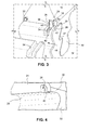
FIG. 3 is a partial perspective view of the turbine spacer disk with a rim seal installed, utilizing two of the three retention components shown inFIG. 1 ; -
FIG. 4 is a partial perspective view illustrating in isolation, a stop key notch formed in the end face of the rim seal shown inFIG. 3 ; -
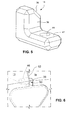
FIG. 5 is a perspective view of the stop key taken fromFIG. 3 ; -
FIG. 6 is a partial perspective view showing the interaction of a stop pin on one rim seal engaged within a notch formed in an adj acent rim seal; -
FIG. 7 is a partial perspective view illustrating the notch formed in the rim seal that receives the stop pin as shown inFIG. 6 ; -
FIG. 8 is a partial perspective view illustrating a locker puck recess formed in the spacer disk; -
FIG. 9 is a perspective view illustrating a locker puck partially received within the recess shown inFIG. 8 but from a different vantage point; -
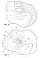
Fig 10 is a section view showing the locker puck ofFIG. 9 in combination with a rim seal installed on the spacer disk; -
FIG. 11 is a partial perspective view illustrating the locker puck located between the rim seal and the spacer disk; -
FIG. 12 illustrates a bolt actuator in accordance with another exemplary embodiment; -
FIG. 13 illustrates the bolt ofFIG. 12 with a locker puck attached; and -
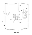
FIG. 14 illustrates an axial movement prevention device employed with rim seals installed about the spacer disk in accordance with an alternative exemplary embodiment. - In the exemplary but nonlimiting embodiment, the axial retention system for the rotor spacer disk rim seals is made up of three components. As will be explained in further detail below, not all of the components are used with every rim seal. In this regard, it will be appreciated that the rim seals are loaded axially onto the spacer disk. The assembly is done in a sequential manner, and the system as disclosed herein utilizes at least two of the components for all but the finally-installed rim seal. A third component is employed with the finally-installed seal (also referred to as the "locker seal") to effectively lock the entire array of seals to the spacer disk.
- Thus with reference initially to
FIGs. 1 and2 , arim seal 10 is shown, in schematic form, axially loaded onto therotor spacer disk 12. Therim seal 10 interfaces withadjacent turbine components shear key 18, a back-uppin 20 and a locker "puck" (also referred to herein as a lock block)22.FIGs. 1 and2 are intended to show the components utilized during installation for convenience and ease of understanding but, for all but one of therim seals 10 loaded onto thespacer disk 12, only theshear key 18 and back-uppin 20 are utilized. The last rim seal orlocker seal 10 installed on the spacer disk utilizes thelocker puck 22, but not theshear key 18 or back-uppin 20, as further explained below. - With reference now also to
FIGs. 3 and 4 , onecircumferential end face 24 of therim seal 10 is formed with a radially-oriented notch 26 adjacent the entry end of thespacer disk slot 27, opening from thebottom surface 28 of aflange portion 30 of the rim seal as well as from theend face 24. Thenotch 26 is otherwise closed in circumferential and axial directions. Thenotch 26 is located to align radially with a discontinuousannular groove 34 formed in thespacer disk 12 upon installation of the rim seal 10 (sometimes referred to herein simply as "theseal 10"). It will be appreciated that thegroove 34 andnotch 26 may be located further away from the entry end of thedisk slot 27 if desired. - The L-shaped shear key 18 (see also
FIG. 5 ) is located in thegroove 34 andnotch 26 as best seen inFIG. 3 . The dimensions and shape of theshear key 18 are such that it can be located in only one orientation, making installation fool-proof. More specifically, the radially outwardly extending leg orstem 36 of the L-shaped shear key is formed with anangled corner 38 that mates with a correspondingly-shapedangled corner 40 of thenotch 26. The horizontal (or circumferential) leg orbase 42 of the L-shaped shear key 18 sits in thegroove 34. It will be appreciated that theshear key 18 can be located in thegroove 34 andnotch 26 after theseal 10 is axially loaded onto thespacer disk 12 or, alternatively, theshear key 18 can be located in thegroove 34, laterally away from theseal 10 and moved into engagement with thenotch 26 after theseal 10 is installed. - Note also the
aperture 44 formed in thebase 42 of theshear key 18. This allows easy removal of the shear key with the use of a suitable tool (not shown). It is not necessary, however, to secure or fix theshear key 18 within thenotch 26 and/orgroove 34. Since the next adjacent rim seal abuts therim seal 10 and overlies thebase 42 of thekey 18, further movement of the shear key is precluded. Theshear key 18 thus prevents movement of therim seal 10 in either axial direction, and the shear key is itself locked into place by the next adjacent seal. - The
circumferential end face 24 of theseal 10 is also formed with a blind bore 46 (FIG. 6 ) at the opposite end of theface 24 from theshear key 18. Thebore 46 receives the back-up stop pin 20 (cylindrical in the example embodiment) via a press fit, or by other suitable means, leaving a portion of thepin 20 exposed. Like theshear key 18, thestop pin 20 prevents axial movement of therim seal 10 in at least one axial direction, as described further below, thus providing a back-up function in the event that theshear key 18 has been inadvertently omitted during installation of the seal. - With reference specifically to
FIGs. 3 and6 , it will be appreciated that the next adjacent seal can be slid axially along itsdovetail groove 48 formed in the spacer disk, passing by (and over) thebase 42 of theshear key 18 and stopping when theaxial stop pin 20 engages within an open notch 50 (FIGs. 6 ,7 ) formed in thecircumferential end face 52 of a nextadjacent seal 54. Thenotch wall 56 thus serves as the stop limit for the axial installation movement in one direction of the next adjacent seal, and the next-installed shear key then also precludes any axial movement in both the installation and opposite directions. - Now with reference to
FIGs. 8-11 in order to lock thefinal seal 58 in place, the third retention component is utilized. An oblong or oval locker "puck" 22 is shaped and sized to fit in and between vertically-adjacent,recesses spacer disk 12 andseal 58, respectively. More specifically, the oblong oroval recess 60 is formed in the upper (radially outer)surface 64 of the spacer disk post 66 (FIG. 8 ). The recess 62 (FIGs. 10-11 ) is formed in the radiallyinner surface 68 of theseal flange portion 70, therecesses seal 58 is loaded into thespacer disk 12. - A
threaded bore 72 extends vertically or radially through thepuck 22 and a threaded adjustment stud orscrew 74 extends through thepuck 22. Abore 76 may be formed in the seal and extends radially outwardly to an access location, where a tool may be inserted. The tool is designed to engage a surface feature 78 (e.g., an Allen-wrench recess) formed in the end of the stud orscrew 74. When thestud 74 is rotated by the tool, thepuck 22 moves along the stud because the puck is held in a non-round recess. Thus, rotation of thestud 74 in a clockwise direction causes thepuck 22 to move radially outward to the position shown inFIGs. 9-11 , where the puck is partially-engaged in bothrecesses locker puck 22 thus locks thefinal seal 58 in place and, in so doing, in combination with the shear keys and back-up pins, locks all of the rim seals against any axial movement within thespacer disk 12. Note in this regard that if all of the shear keys were omitted, all of the seals except the finally-installed seal would be locked in one axial direction only, because the back-up pins prevent axial movement in only one direction. - Note also that for the
final rim seal 58, neither shear key 18 nor the back uppin 20 are used. - Alternatively, an elongated bolt 80 (
FIGs. 12, 13 ) with a threadedend 82 may be used to engage thepuck 22. Thebolt 80 will extend through thebore 76 and rotation of the bolt will cause thepuck 22 to move axially along the threaded end 82 (and radially relative to the spacer disk) substantially as described above. A fail or weak point in the form ofgroove 84 may be provided in thebolt shank 86 adjacent the threadedend 82 to facilitate breaking and removal of the bolt shank after installation if desired. - In another alternative arrangement, a
frangible shim 88 is integrally attached to the lower part of the threadedshank 74 as shown inFIG. 14 , in conjunction with anextended receptacle portion 90 provided in the disk, radially inward of therecess 60. This allows theshank 74 to be punched radially into thereceptacle portion 90, causing thepuck 22 to fall back into the rotor disk, thus providing an alternative technique for releasing the rim seal for axial movement. - With the above-described arrangement, all components, i.e., the
shear key 36,locker puck 22 and stoppin 20 are enclosed within the rim seal/spacer disk so that in the event of failure, the components are substantially precluded from dropping into the internal wheel space of the rotor. - It will also be appreciated that the
locker puck 22 may be utilized in the three-component system as described above, or, alternatively, as a stand-alone retention device used in connection with any one or all of the rim seals. Moreover, thelocker puck 22 can be employed in any other application where retention of one component in a slot formed in a second component is desired. - While the invention has been described in connection with what is presently considered to be the most practical and preferred embodiment, it is to be understood that the invention is not to be limited to the disclosed embodiment, but on the contrary, is intended to cover various modifications and equivalent arrangements included within the spirit and scope of the appended claims.
Claims (12)
- A retention device for maintaining a first rotary machine component (10) axially loaded onto a second rotary machine component (12) in a fixed axial position, the retention device comprising:a block (22) sized and configured to move between first and second aligned recesses (60,62) in the first and second rotary machine components (10,12), the aligned recesses (60,62) shaped to prevent rotation of said block (22), said block (22) having a threaded bore (72) extending at least partially therethrough; andan actuator (74) threadably mounted in said bore (72), such that rotation of said actuator (74) will, in use, move said block (22) from the first aligned recess (60) at least partially into said second aligned recess (62).
- The retention device of claim 1, wherein said actuator (74) comprises a stud (74) engageable by a tool.
- The retention device of claim 1 or 2, wherein said actuator (74) comprises an elongated bolt with a threaded end adapted to be received in said bore (72).
- The retention device of any of claims 1 to 3, wherein said block (22) is oblong or oval-shaped.
- The retention device of any of claims 1 to 4, wherein said first rotary component (10) comprises a rotor spacer disk rim seal (10) and said second rotary component (12) comprises a rotor spacer disk (12).
- An axial retention system for a plurality of rim seals axially loaded onto a rotor spacer disk (12), the axial retention system comprising:a shear key (18) adapted to be inserted between an annular circumferential groove (34) in said rotor spacer disk (12) and a radial notch (26) formed in an end face (24) of said rim seal (10); andthe retention device of any of claims 1 to 5.
- The axial retention system of claim 6 and further comprising a back-up stop pin (20) extending from said end face (24) and receivable in a notch (26) formed in an end face (24) of a next adjacent rim seal (10).
- The axial retention system of claim 6 or 7, wherein said shear key (18) is substantially L-shaped, a base portion (42) received in said circumferential groove (34) and an upright stem portion (36) received in said radial notch (26).
- The axial retention system of claim 6, 7 or 8, wherein said first and second recesses (60,62) and said lock block (22) are shaped to prevent rotation of said block (22).
- The retention system of any of claims 6 to 9, wherein each rim seal (10) except for a finally-installed locker seal, comprises the shear key (98).
- The retention of claim 10, wherein said finally-installed locker seal includes the block (22).
- The retention system of any of claims 6 to 11, wherein said first recess (60) in said spacer disk (12) is provided with an extended receptacle portion (90) covered by a frangible shim, said extended receptacle (90) adapted to receive said stud (74) to thereby permit said block (22) to move from said position straddling said first and second recesses (60,62) to a release position where said block is seated entirely within said second recess (62).
Applications Claiming Priority (1)
| Application Number | Priority Date | Filing Date | Title |
|---|---|---|---|
| US13/344,296 US9890648B2 (en) | 2012-01-05 | 2012-01-05 | Turbine rotor rim seal axial retention assembly |
Publications (3)
| Publication Number | Publication Date |
|---|---|
| EP2613001A2 true EP2613001A2 (en) | 2013-07-10 |
| EP2613001A3 EP2613001A3 (en) | 2018-03-07 |
| EP2613001B1 EP2613001B1 (en) | 2020-07-01 |
Family
ID=47678525
Family Applications (1)
| Application Number | Title | Priority Date | Filing Date |
|---|---|---|---|
| EP12199292.9A Active EP2613001B1 (en) | 2012-01-05 | 2012-12-21 | Axial retention system for turbine rotor rim seals |
Country Status (5)
| Country | Link |
|---|---|
| US (1) | US9890648B2 (en) |
| EP (1) | EP2613001B1 (en) |
| JP (1) | JP6302160B2 (en) |
| CN (1) | CN103195514B (en) |
| RU (1) | RU2620463C2 (en) |
Cited By (1)
| Publication number | Priority date | Publication date | Assignee | Title |
|---|---|---|---|---|
| EP3128131A1 (en) * | 2015-08-03 | 2017-02-08 | Doosan Heavy Industries & Construction Co., Ltd. | Assembling method of turbine buckets and a fixture for turbine buckets |
Families Citing this family (4)
| Publication number | Priority date | Publication date | Assignee | Title |
|---|---|---|---|---|
| WO2015112238A1 (en) | 2014-01-24 | 2015-07-30 | United Technologies Corporation | Toggle seal for a rim seal |
| US10274016B2 (en) * | 2017-03-28 | 2019-04-30 | General Electric Company | Turbine engine bearing assembly and method for assembling the same |
| US10669874B2 (en) * | 2017-05-01 | 2020-06-02 | General Electric Company | Discourager for discouraging flow through flow path gaps |
| CN108798789B (en) * | 2018-06-07 | 2020-12-08 | 中国航发湖南动力机械研究所 | Locking plate stop mechanism and turbine disc assembly |
Family Cites Families (23)
| Publication number | Priority date | Publication date | Assignee | Title |
|---|---|---|---|---|
| JPS59192801A (en) * | 1983-04-15 | 1984-11-01 | Hitachi Ltd | Easily detachable moving blade fixing method |
| US4676723A (en) | 1986-03-26 | 1987-06-30 | Westinghouse Electric Corp. | Locking system for a turbine side entry blade |
| US4767275A (en) * | 1986-07-11 | 1988-08-30 | Westinghouse Electric Corp. | Locking pin system for turbine curved root side entry closing blades |
| US5080556A (en) * | 1990-09-28 | 1992-01-14 | General Electric Company | Thermal seal for a gas turbine spacer disc |
| US6042336A (en) * | 1998-11-25 | 2000-03-28 | United Technologies Corporation | Offset center of gravity radial damper |
| US6148518A (en) * | 1998-12-22 | 2000-11-21 | United Technologies Corporation | Method of assembling a rotary machine |
| JP2000303994A (en) * | 1999-04-26 | 2000-10-31 | Toshiba Corp | Axial compressor |
| US6190131B1 (en) | 1999-08-31 | 2001-02-20 | General Electric Co. | Non-integral balanced coverplate and coverplate centering slot for a turbine |
| DE10120532A1 (en) * | 2001-04-26 | 2002-10-31 | Alstom Switzerland Ltd | Device and method for fastening a rotor blade along a circumferential groove running within a rotor of an axially flowed through turbomachine |
| JP3762661B2 (en) * | 2001-05-31 | 2006-04-05 | 株式会社日立製作所 | Turbine rotor |
| ITMI20012783A1 (en) | 2001-12-21 | 2003-06-21 | Nuovo Pignone Spa | CONNECTION AND LOCKING SYSTEM OF ROTORIAL BLADES OF AN AXIAL COMPRESSOR |
| US6814538B2 (en) | 2003-01-22 | 2004-11-09 | General Electric Company | Turbine stage one shroud configuration and method for service enhancement |
| US7435055B2 (en) * | 2005-03-29 | 2008-10-14 | Siemens Power Generation, Inc. | Locking spacer assembly for a turbine engine |
| CN101258305B (en) | 2005-09-07 | 2011-06-15 | 西门子公司 | Device for axially securing moving blades in a rotor, seal for such a device and use of such a device |
| US7419355B2 (en) * | 2006-02-15 | 2008-09-02 | General Electric Company | Methods and apparatus for nozzle carrier with trapped shim adjustment |
| US7931442B1 (en) * | 2007-05-31 | 2011-04-26 | Florida Turbine Technologies, Inc. | Rotor blade assembly with de-coupled composite platform |
| US8007245B2 (en) | 2007-11-29 | 2011-08-30 | General Electric Company | Shank shape for a turbine blade and turbine incorporating the same |
| US8061995B2 (en) | 2008-01-10 | 2011-11-22 | General Electric Company | Machine component retention |
| JP4886735B2 (en) * | 2008-05-26 | 2012-02-29 | 株式会社東芝 | Turbine blade assembly and steam turbine |
| US8096775B2 (en) | 2008-09-08 | 2012-01-17 | General Electric Company | Steam turbine rotating blade for a low pressure section of a steam turbine engine |
| US8075272B2 (en) | 2008-10-14 | 2011-12-13 | General Electric Company | Steam turbine rotating blade for a low pressure section of a steam turbine engine |
| CN201339495Y (en) * | 2009-02-04 | 2009-11-04 | 陈熙祖 | Improved cushion block regulating structure of steam turbine half bearing |
| US8007230B2 (en) | 2010-01-05 | 2011-08-30 | General Electric Company | Turbine seal plate assembly |
-
2012
- 2012-01-05 US US13/344,296 patent/US9890648B2/en active Active
- 2012-12-19 JP JP2012276309A patent/JP6302160B2/en active Active
- 2012-12-21 EP EP12199292.9A patent/EP2613001B1/en active Active
- 2012-12-27 RU RU2012158311A patent/RU2620463C2/en active
-
2013
- 2013-01-04 CN CN201310001302.6A patent/CN103195514B/en active Active
Non-Patent Citations (1)
| Title |
|---|
| None |
Cited By (2)
| Publication number | Priority date | Publication date | Assignee | Title |
|---|---|---|---|---|
| EP3128131A1 (en) * | 2015-08-03 | 2017-02-08 | Doosan Heavy Industries & Construction Co., Ltd. | Assembling method of turbine buckets and a fixture for turbine buckets |
| US10358930B2 (en) | 2015-08-03 | 2019-07-23 | DOOSAN Heavy Industries Construction Co., LTD | Assembling method of a bucket and a fixture for a bucket for a turbine blade |
Also Published As
| Publication number | Publication date |
|---|---|
| CN103195514B (en) | 2016-08-31 |
| US9890648B2 (en) | 2018-02-13 |
| JP2013139777A (en) | 2013-07-18 |
| RU2620463C2 (en) | 2017-05-25 |
| US20130175230A1 (en) | 2013-07-11 |
| EP2613001B1 (en) | 2020-07-01 |
| CN103195514A (en) | 2013-07-10 |
| JP6302160B2 (en) | 2018-03-28 |
| RU2012158311A (en) | 2014-07-10 |
| EP2613001A3 (en) | 2018-03-07 |
Similar Documents
| Publication | Publication Date | Title |
|---|---|---|
| EP2613001A2 (en) | Turbine Rotor Rim Seal Axial Retention Assembly | |
| US9021843B2 (en) | Hybrid lock cylinder | |
| US20060073021A1 (en) | Remotely accessible locking system for turbine blades | |
| JP2010156337A (en) | Hook-to-hook engagement for rotor dovetail | |
| US20140348613A1 (en) | Nut And/Or Bolt Head With Jackscrew Actuated Lock Washer Stack | |
| KR101942209B1 (en) | Blade fastening mechanism with fasteners for turbine blades | |
| BR102016007846B1 (en) | ACTUATOR FOR VARIING A POSITION OF A FLIGHT CONTROL SURFACE ON AN AIRCRAFT, AND, METHOD FOR ADJUSTING CLEARANCE ON A FLIGHT CONTROL SURFACE ACTUATOR | |
| EP2163728B1 (en) | Load pin square base for compressor stator | |
| US9279458B2 (en) | Angular positioning arrangement | |
| US7704028B2 (en) | Bore serration for locking threaded inserts against rotation | |
| US20060291953A1 (en) | Device for rotationally locking a clamping nut for a component on a shaft, clamping nut and shaft comprising it, and aircraft engine equipped therewith | |
| US8834124B2 (en) | Device for attaching hammer clamp blades, associated compressor hub, compressor and turbine engine | |
| CN104213941B (en) | turbine blades | |
| US20160252124A1 (en) | Releasable fastener | |
| US11614112B2 (en) | Temporary clamping fastener with expandable clamp blade | |
| RU2700309C2 (en) | Turbomachine, locking device for blades and method of fixing blade | |
| US10801529B2 (en) | Magnetic failsafe piston retention assembly, and related components, systems, and methods | |
| US20170241276A1 (en) | Wheel disk assembly having sealing plates | |
| US9482335B2 (en) | No-back check device | |
| US6623242B2 (en) | Torque pin | |
| US20150089983A1 (en) | Lock Mechanism with a Key Removal Interlock and an Interlock of Key Removal from a Lock Mechanism | |
| JPS6229703A (en) | Locking mechanism for gas turbine bucket | |
| JP6430362B2 (en) | Equipment with adjustment bolt | |
| CN104160113B (en) | For the active wheel of the rotor of turbo machine and rotor and the turbo machine with this active wheel | |
| CN105569458A (en) | Door lock assembly and complete automobile test environment chamber |
Legal Events
| Date | Code | Title | Description |
|---|---|---|---|
| PUAI | Public reference made under article 153(3) epc to a published international application that has entered the european phase |
Free format text: ORIGINAL CODE: 0009012 |
|
| AK | Designated contracting states |
Kind code of ref document: A2 Designated state(s): AL AT BE BG CH CY CZ DE DK EE ES FI FR GB GR HR HU IE IS IT LI LT LU LV MC MK MT NL NO PL PT RO RS SE SI SK SM TR |
|
| AX | Request for extension of the european patent |
Extension state: BA ME |
|
| PUAL | Search report despatched |
Free format text: ORIGINAL CODE: 0009013 |
|
| AK | Designated contracting states |
Kind code of ref document: A3 Designated state(s): AL AT BE BG CH CY CZ DE DK EE ES FI FR GB GR HR HU IE IS IT LI LT LU LV MC MK MT NL NO PL PT RO RS SE SI SK SM TR |
|
| AX | Request for extension of the european patent |
Extension state: BA ME |
|
| RIC1 | Information provided on ipc code assigned before grant |
Ipc: F01D 5/32 20060101AFI20180201BHEP |
|
| STAA | Information on the status of an ep patent application or granted ep patent |
Free format text: STATUS: REQUEST FOR EXAMINATION WAS MADE |
|
| 17P | Request for examination filed |
Effective date: 20180907 |
|
| RBV | Designated contracting states (corrected) |
Designated state(s): AL AT BE BG CH CY CZ DE DK EE ES FI FR GB GR HR HU IE IS IT LI LT LU LV MC MK MT NL NO PL PT RO RS SE SI SK SM TR |
|
| STAA | Information on the status of an ep patent application or granted ep patent |
Free format text: STATUS: EXAMINATION IS IN PROGRESS |
|
| 17Q | First examination report despatched |
Effective date: 20190411 |
|
| GRAP | Despatch of communication of intention to grant a patent |
Free format text: ORIGINAL CODE: EPIDOSNIGR1 |
|
| STAA | Information on the status of an ep patent application or granted ep patent |
Free format text: STATUS: GRANT OF PATENT IS INTENDED |
|
| INTG | Intention to grant announced |
Effective date: 20200124 |
|
| GRAS | Grant fee paid |
Free format text: ORIGINAL CODE: EPIDOSNIGR3 |
|
| GRAA | (expected) grant |
Free format text: ORIGINAL CODE: 0009210 |
|
| STAA | Information on the status of an ep patent application or granted ep patent |
Free format text: STATUS: THE PATENT HAS BEEN GRANTED |
|
| AK | Designated contracting states |
Kind code of ref document: B1 Designated state(s): AL AT BE BG CH CY CZ DE DK EE ES FI FR GB GR HR HU IE IS IT LI LT LU LV MC MK MT NL NO PL PT RO RS SE SI SK SM TR |
|
| REG | Reference to a national code |
Ref country code: GB Ref legal event code: FG4D |
|
| REG | Reference to a national code |
Ref country code: AT Ref legal event code: REF Ref document number: 1286363 Country of ref document: AT Kind code of ref document: T Effective date: 20200715 Ref country code: CH Ref legal event code: EP |
|
| REG | Reference to a national code |
Ref country code: IE Ref legal event code: FG4D |
|
| REG | Reference to a national code |
Ref country code: DE Ref legal event code: R096 Ref document number: 602012070997 Country of ref document: DE |
|
| REG | Reference to a national code |
Ref country code: LT Ref legal event code: MG4D |
|
| PG25 | Lapsed in a contracting state [announced via postgrant information from national office to epo] |
Ref country code: BG Free format text: LAPSE BECAUSE OF FAILURE TO SUBMIT A TRANSLATION OF THE DESCRIPTION OR TO PAY THE FEE WITHIN THE PRESCRIBED TIME-LIMIT Effective date: 20201001 |
|
| REG | Reference to a national code |
Ref country code: NL Ref legal event code: MP Effective date: 20200701 |
|
| REG | Reference to a national code |
Ref country code: AT Ref legal event code: MK05 Ref document number: 1286363 Country of ref document: AT Kind code of ref document: T Effective date: 20200701 |
|
| PG25 | Lapsed in a contracting state [announced via postgrant information from national office to epo] |
Ref country code: CZ Free format text: LAPSE BECAUSE OF FAILURE TO SUBMIT A TRANSLATION OF THE DESCRIPTION OR TO PAY THE FEE WITHIN THE PRESCRIBED TIME-LIMIT Effective date: 20200701 Ref country code: PT Free format text: LAPSE BECAUSE OF FAILURE TO SUBMIT A TRANSLATION OF THE DESCRIPTION OR TO PAY THE FEE WITHIN THE PRESCRIBED TIME-LIMIT Effective date: 20201102 Ref country code: AT Free format text: LAPSE BECAUSE OF FAILURE TO SUBMIT A TRANSLATION OF THE DESCRIPTION OR TO PAY THE FEE WITHIN THE PRESCRIBED TIME-LIMIT Effective date: 20200701 Ref country code: ES Free format text: LAPSE BECAUSE OF FAILURE TO SUBMIT A TRANSLATION OF THE DESCRIPTION OR TO PAY THE FEE WITHIN THE PRESCRIBED TIME-LIMIT Effective date: 20200701 Ref country code: NO Free format text: LAPSE BECAUSE OF FAILURE TO SUBMIT A TRANSLATION OF THE DESCRIPTION OR TO PAY THE FEE WITHIN THE PRESCRIBED TIME-LIMIT Effective date: 20201001 Ref country code: GR Free format text: LAPSE BECAUSE OF FAILURE TO SUBMIT A TRANSLATION OF THE DESCRIPTION OR TO PAY THE FEE WITHIN THE PRESCRIBED TIME-LIMIT Effective date: 20201002 Ref country code: SE Free format text: LAPSE BECAUSE OF FAILURE TO SUBMIT A TRANSLATION OF THE DESCRIPTION OR TO PAY THE FEE WITHIN THE PRESCRIBED TIME-LIMIT Effective date: 20200701 Ref country code: HR Free format text: LAPSE BECAUSE OF FAILURE TO SUBMIT A TRANSLATION OF THE DESCRIPTION OR TO PAY THE FEE WITHIN THE PRESCRIBED TIME-LIMIT Effective date: 20200701 Ref country code: LT Free format text: LAPSE BECAUSE OF FAILURE TO SUBMIT A TRANSLATION OF THE DESCRIPTION OR TO PAY THE FEE WITHIN THE PRESCRIBED TIME-LIMIT Effective date: 20200701 Ref country code: FI Free format text: LAPSE BECAUSE OF FAILURE TO SUBMIT A TRANSLATION OF THE DESCRIPTION OR TO PAY THE FEE WITHIN THE PRESCRIBED TIME-LIMIT Effective date: 20200701 |
|
| PG25 | Lapsed in a contracting state [announced via postgrant information from national office to epo] |
Ref country code: IS Free format text: LAPSE BECAUSE OF FAILURE TO SUBMIT A TRANSLATION OF THE DESCRIPTION OR TO PAY THE FEE WITHIN THE PRESCRIBED TIME-LIMIT Effective date: 20201101 Ref country code: LV Free format text: LAPSE BECAUSE OF FAILURE TO SUBMIT A TRANSLATION OF THE DESCRIPTION OR TO PAY THE FEE WITHIN THE PRESCRIBED TIME-LIMIT Effective date: 20200701 Ref country code: PL Free format text: LAPSE BECAUSE OF FAILURE TO SUBMIT A TRANSLATION OF THE DESCRIPTION OR TO PAY THE FEE WITHIN THE PRESCRIBED TIME-LIMIT Effective date: 20200701 Ref country code: RS Free format text: LAPSE BECAUSE OF FAILURE TO SUBMIT A TRANSLATION OF THE DESCRIPTION OR TO PAY THE FEE WITHIN THE PRESCRIBED TIME-LIMIT Effective date: 20200701 |
|
| PG25 | Lapsed in a contracting state [announced via postgrant information from national office to epo] |
Ref country code: NL Free format text: LAPSE BECAUSE OF FAILURE TO SUBMIT A TRANSLATION OF THE DESCRIPTION OR TO PAY THE FEE WITHIN THE PRESCRIBED TIME-LIMIT Effective date: 20200701 |
|
| REG | Reference to a national code |
Ref country code: DE Ref legal event code: R097 Ref document number: 602012070997 Country of ref document: DE |
|
| PG25 | Lapsed in a contracting state [announced via postgrant information from national office to epo] |
Ref country code: SM Free format text: LAPSE BECAUSE OF FAILURE TO SUBMIT A TRANSLATION OF THE DESCRIPTION OR TO PAY THE FEE WITHIN THE PRESCRIBED TIME-LIMIT Effective date: 20200701 Ref country code: RO Free format text: LAPSE BECAUSE OF FAILURE TO SUBMIT A TRANSLATION OF THE DESCRIPTION OR TO PAY THE FEE WITHIN THE PRESCRIBED TIME-LIMIT Effective date: 20200701 Ref country code: IT Free format text: LAPSE BECAUSE OF FAILURE TO SUBMIT A TRANSLATION OF THE DESCRIPTION OR TO PAY THE FEE WITHIN THE PRESCRIBED TIME-LIMIT Effective date: 20200701 Ref country code: EE Free format text: LAPSE BECAUSE OF FAILURE TO SUBMIT A TRANSLATION OF THE DESCRIPTION OR TO PAY THE FEE WITHIN THE PRESCRIBED TIME-LIMIT Effective date: 20200701 Ref country code: DK Free format text: LAPSE BECAUSE OF FAILURE TO SUBMIT A TRANSLATION OF THE DESCRIPTION OR TO PAY THE FEE WITHIN THE PRESCRIBED TIME-LIMIT Effective date: 20200701 |
|
| PLBE | No opposition filed within time limit |
Free format text: ORIGINAL CODE: 0009261 |
|
| STAA | Information on the status of an ep patent application or granted ep patent |
Free format text: STATUS: NO OPPOSITION FILED WITHIN TIME LIMIT |
|
| PG25 | Lapsed in a contracting state [announced via postgrant information from national office to epo] |
Ref country code: AL Free format text: LAPSE BECAUSE OF FAILURE TO SUBMIT A TRANSLATION OF THE DESCRIPTION OR TO PAY THE FEE WITHIN THE PRESCRIBED TIME-LIMIT Effective date: 20200701 |
|
| 26N | No opposition filed |
Effective date: 20210406 |
|
| PG25 | Lapsed in a contracting state [announced via postgrant information from national office to epo] |
Ref country code: SK Free format text: LAPSE BECAUSE OF FAILURE TO SUBMIT A TRANSLATION OF THE DESCRIPTION OR TO PAY THE FEE WITHIN THE PRESCRIBED TIME-LIMIT Effective date: 20200701 |
|
| REG | Reference to a national code |
Ref country code: CH Ref legal event code: PL |
|
| GBPC | Gb: european patent ceased through non-payment of renewal fee |
Effective date: 20201221 |
|
| PG25 | Lapsed in a contracting state [announced via postgrant information from national office to epo] |
Ref country code: MC Free format text: LAPSE BECAUSE OF FAILURE TO SUBMIT A TRANSLATION OF THE DESCRIPTION OR TO PAY THE FEE WITHIN THE PRESCRIBED TIME-LIMIT Effective date: 20200701 Ref country code: SI Free format text: LAPSE BECAUSE OF FAILURE TO SUBMIT A TRANSLATION OF THE DESCRIPTION OR TO PAY THE FEE WITHIN THE PRESCRIBED TIME-LIMIT Effective date: 20200701 |
|
| REG | Reference to a national code |
Ref country code: BE Ref legal event code: MM Effective date: 20201231 |
|
| PG25 | Lapsed in a contracting state [announced via postgrant information from national office to epo] |
Ref country code: IE Free format text: LAPSE BECAUSE OF NON-PAYMENT OF DUE FEES Effective date: 20201221 Ref country code: LU Free format text: LAPSE BECAUSE OF NON-PAYMENT OF DUE FEES Effective date: 20201221 Ref country code: FR Free format text: LAPSE BECAUSE OF NON-PAYMENT OF DUE FEES Effective date: 20201231 |
|
| PG25 | Lapsed in a contracting state [announced via postgrant information from national office to epo] |
Ref country code: LI Free format text: LAPSE BECAUSE OF NON-PAYMENT OF DUE FEES Effective date: 20201231 Ref country code: CH Free format text: LAPSE BECAUSE OF NON-PAYMENT OF DUE FEES Effective date: 20201231 Ref country code: GB Free format text: LAPSE BECAUSE OF NON-PAYMENT OF DUE FEES Effective date: 20201221 |
|
| PG25 | Lapsed in a contracting state [announced via postgrant information from national office to epo] |
Ref country code: IS Free format text: LAPSE BECAUSE OF FAILURE TO SUBMIT A TRANSLATION OF THE DESCRIPTION OR TO PAY THE FEE WITHIN THE PRESCRIBED TIME-LIMIT Effective date: 20201101 Ref country code: TR Free format text: LAPSE BECAUSE OF FAILURE TO SUBMIT A TRANSLATION OF THE DESCRIPTION OR TO PAY THE FEE WITHIN THE PRESCRIBED TIME-LIMIT Effective date: 20200701 Ref country code: MT Free format text: LAPSE BECAUSE OF FAILURE TO SUBMIT A TRANSLATION OF THE DESCRIPTION OR TO PAY THE FEE WITHIN THE PRESCRIBED TIME-LIMIT Effective date: 20200701 Ref country code: CY Free format text: LAPSE BECAUSE OF FAILURE TO SUBMIT A TRANSLATION OF THE DESCRIPTION OR TO PAY THE FEE WITHIN THE PRESCRIBED TIME-LIMIT Effective date: 20200701 |
|
| PG25 | Lapsed in a contracting state [announced via postgrant information from national office to epo] |
Ref country code: MK Free format text: LAPSE BECAUSE OF FAILURE TO SUBMIT A TRANSLATION OF THE DESCRIPTION OR TO PAY THE FEE WITHIN THE PRESCRIBED TIME-LIMIT Effective date: 20200701 |
|
| PG25 | Lapsed in a contracting state [announced via postgrant information from national office to epo] |
Ref country code: BE Free format text: LAPSE BECAUSE OF NON-PAYMENT OF DUE FEES Effective date: 20201231 |
|
| P01 | Opt-out of the competence of the unified patent court (upc) registered |
Effective date: 20230522 |
|
| REG | Reference to a national code |
Ref country code: DE Ref legal event code: R081 Ref document number: 602012070997 Country of ref document: DE Owner name: GENERAL ELECTRIC TECHNOLOGY GMBH, CH Free format text: FORMER OWNER: GENERAL ELECTRIC COMPANY, SCHENECTADY, NY, US |
|
| PGFP | Annual fee paid to national office [announced via postgrant information from national office to epo] |
Ref country code: DE Payment date: 20251126 Year of fee payment: 14 |