EP2612841B1 - Constructed wetland wastewater treatment equipment for continuous operation at low temperatures - Google Patents
Constructed wetland wastewater treatment equipment for continuous operation at low temperatures Download PDFInfo
- Publication number
- EP2612841B1 EP2612841B1 EP20120171182 EP12171182A EP2612841B1 EP 2612841 B1 EP2612841 B1 EP 2612841B1 EP 20120171182 EP20120171182 EP 20120171182 EP 12171182 A EP12171182 A EP 12171182A EP 2612841 B1 EP2612841 B1 EP 2612841B1
- Authority
- EP
- European Patent Office
- Prior art keywords
- water
- pipe
- substrates
- constructed wetland
- wastewater treatment
- Prior art date
- Legal status (The legal status is an assumption and is not a legal conclusion. Google has not performed a legal analysis and makes no representation as to the accuracy of the status listed.)
- Not-in-force
Links
- 238000004065 wastewater treatment Methods 0.000 title claims description 19
- XLYOFNOQVPJJNP-UHFFFAOYSA-N water Substances O XLYOFNOQVPJJNP-UHFFFAOYSA-N 0.000 claims description 212
- 239000000758 substrate Substances 0.000 claims description 50
- 238000004321 preservation Methods 0.000 claims description 15
- 235000019738 Limestone Nutrition 0.000 claims description 9
- 230000020169 heat generation Effects 0.000 claims description 9
- 239000006028 limestone Substances 0.000 claims description 9
- 239000002245 particle Substances 0.000 claims description 7
- 238000009423 ventilation Methods 0.000 claims description 7
- OKTJSMMVPCPJKN-UHFFFAOYSA-N Carbon Chemical compound [C] OKTJSMMVPCPJKN-UHFFFAOYSA-N 0.000 claims description 3
- 229910021536 Zeolite Inorganic materials 0.000 claims description 3
- 230000004888 barrier function Effects 0.000 claims description 3
- 229910052799 carbon Inorganic materials 0.000 claims description 3
- HNPSIPDUKPIQMN-UHFFFAOYSA-N dioxosilane;oxo(oxoalumanyloxy)alumane Chemical compound O=[Si]=O.O=[Al]O[Al]=O HNPSIPDUKPIQMN-UHFFFAOYSA-N 0.000 claims description 3
- -1 gravel Substances 0.000 claims description 3
- 239000002893 slag Substances 0.000 claims description 3
- 239000000126 substance Substances 0.000 claims description 3
- 239000010457 zeolite Substances 0.000 claims description 3
- 238000005202 decontamination Methods 0.000 claims description 2
- 230000003588 decontaminative effect Effects 0.000 claims description 2
- 239000000203 mixture Substances 0.000 description 9
- 235000005324 Typha latifolia Nutrition 0.000 description 7
- 244000118869 coast club rush Species 0.000 description 7
- 230000000694 effects Effects 0.000 description 7
- 239000010802 sludge Substances 0.000 description 6
- QVGXLLKOCUKJST-UHFFFAOYSA-N atomic oxygen Chemical compound [O] QVGXLLKOCUKJST-UHFFFAOYSA-N 0.000 description 5
- 239000001301 oxygen Substances 0.000 description 5
- 229910052760 oxygen Inorganic materials 0.000 description 5
- 239000007789 gas Substances 0.000 description 4
- 244000005700 microbiome Species 0.000 description 3
- IJGRMHOSHXDMSA-UHFFFAOYSA-N Atomic nitrogen Chemical compound N#N IJGRMHOSHXDMSA-UHFFFAOYSA-N 0.000 description 2
- VNWKTOKETHGBQD-UHFFFAOYSA-N methane Chemical compound C VNWKTOKETHGBQD-UHFFFAOYSA-N 0.000 description 2
- 239000003895 organic fertilizer Substances 0.000 description 2
- 230000001131 transforming effect Effects 0.000 description 2
- 241000196324 Embryophyta Species 0.000 description 1
- OAICVXFJPJFONN-UHFFFAOYSA-N Phosphorus Chemical compound [P] OAICVXFJPJFONN-UHFFFAOYSA-N 0.000 description 1
- 238000010564 aerobic fermentation Methods 0.000 description 1
- 230000000903 blocking effect Effects 0.000 description 1
- 239000000356 contaminant Substances 0.000 description 1
- 238000011109 contamination Methods 0.000 description 1
- 238000000855 fermentation Methods 0.000 description 1
- 238000007710 freezing Methods 0.000 description 1
- 230000008014 freezing Effects 0.000 description 1
- 239000003673 groundwater Substances 0.000 description 1
- 239000011159 matrix material Substances 0.000 description 1
- 230000002503 metabolic effect Effects 0.000 description 1
- 238000000034 method Methods 0.000 description 1
- 229910052757 nitrogen Inorganic materials 0.000 description 1
- 230000006641 stabilisation Effects 0.000 description 1
- 238000011105 stabilization Methods 0.000 description 1
- 230000009466 transformation Effects 0.000 description 1
- 238000005406 washing Methods 0.000 description 1
- 239000002699 waste material Substances 0.000 description 1
- 239000002351 wastewater Substances 0.000 description 1
Images

Classifications
-
- C—CHEMISTRY; METALLURGY
- C02—TREATMENT OF WATER, WASTE WATER, SEWAGE, OR SLUDGE
- C02F—TREATMENT OF WATER, WASTE WATER, SEWAGE, OR SLUDGE
- C02F3/00—Biological treatment of water, waste water, or sewage
- C02F3/32—Biological treatment of water, waste water, or sewage characterised by the animals or plants used, e.g. algae
- C02F3/327—Biological treatment of water, waste water, or sewage characterised by the animals or plants used, e.g. algae characterised by animals and plants
-
- C—CHEMISTRY; METALLURGY
- C02—TREATMENT OF WATER, WASTE WATER, SEWAGE, OR SLUDGE
- C02F—TREATMENT OF WATER, WASTE WATER, SEWAGE, OR SLUDGE
- C02F2301/00—General aspects of water treatment
- C02F2301/04—Flow arrangements
-
- C—CHEMISTRY; METALLURGY
- C02—TREATMENT OF WATER, WASTE WATER, SEWAGE, OR SLUDGE
- C02F—TREATMENT OF WATER, WASTE WATER, SEWAGE, OR SLUDGE
- C02F3/00—Biological treatment of water, waste water, or sewage
- C02F3/02—Aerobic processes
- C02F3/06—Aerobic processes using submerged filters
-
- Y—GENERAL TAGGING OF NEW TECHNOLOGICAL DEVELOPMENTS; GENERAL TAGGING OF CROSS-SECTIONAL TECHNOLOGIES SPANNING OVER SEVERAL SECTIONS OF THE IPC; TECHNICAL SUBJECTS COVERED BY FORMER USPC CROSS-REFERENCE ART COLLECTIONS [XRACs] AND DIGESTS
- Y02—TECHNOLOGIES OR APPLICATIONS FOR MITIGATION OR ADAPTATION AGAINST CLIMATE CHANGE
- Y02W—CLIMATE CHANGE MITIGATION TECHNOLOGIES RELATED TO WASTEWATER TREATMENT OR WASTE MANAGEMENT
- Y02W10/00—Technologies for wastewater treatment
- Y02W10/10—Biological treatment of water, waste water, or sewage
Definitions
- the present invention relates to a heat preservation and temperature increasing equipment, and in particular, to a constructed wetland wastewater treatment equipment under low temperature for continuous operation.
- An object of the present invention is to provide a constructed wetland wastewater treatment equipment under low temperature for continuous operation to improve a high removal rate of nitrogen and phosphor, stabilization for a treatment effect and recycle of wastes. Further, the constructed wetland wastewater treatment equipment has a flow transformable function to ensure the constructed wetland to operate continuously and stably.
- the constructed wetland wastewater treatment equipment under low temperature for continuous operation mainly comprises:
- the substrates of the constructed wetland wastewater treatment equipment are a combination of one or more of zeolite, gravel, limestone, slag, active carbon.
- An upper section of substrates connected with the water inlet pipe is 10%-20% in length of a total length of the three-section substrates.
- a middle section of substrates is 70%-85% in length of the total length.
- a lower section of substrates connected with the water outlet pipe is 5%-10% in length of the total length.
- the height of the substrates is 1.6-1.8m, and the height of the bed is 2.2-2.5m.
- particle diameters of the upper section of substrates connected with the water inlet pipe and the lower section of substrates connected with the water outlet pipe are both 16-32 mm, and a particle diameter of the middle section of substrates is 8-16 mm.
- the water distributing pipe and the water inlet pipe are connected to the water head tank by respective water inlet valves.
- the water collecting pipe and the water outlet pipe are provided with respective main control valves and respective sub-control valves at different heights.
- Each of the water collecting pipe and the water outlet pipe is provided with three sub-control valves which are respectively mounted at a position higher than the height of the bed of the constructed wetland, in the middle of the substrates, and at the bottom of the bed of the constructed wetland.
- the water distributing pipe and the water collecting pipe are both made of a PVC pipe with diameters from 100mm to 200mm.
- the water distributing pipe uniformly distributes the water, apertures are arranged on the water distributing pipe at an interval of 10-20cm and a diameter of each of the apertures is 1-3cm.
- the water collecting pipe is provided with water collecting apertures corresponding to the middle section of substrates.
- the water collecting apertures are arranged on the water collecting pipe at an interval of 5-10cm and a diameter of each of the water collecting apertures is 1-3cm.
- the upper layer of the constructed wetland is planted with emerged plants having strong decontamination.
- a leakage-proof layer is coated at the bottom inside of the double wall.
- the flow transformable wetland can mutually transform the horizontal flow wetland and the vertical flow wetland therebetween by adjusting distributing pipes based on the change of the ambient temperature. This overcomes disadvantages that dissolved oxygen of incoming water is low in the horizontal flow wetland in summer and a thermal loss is much in the vertical flow wetland in winter. Thereby, the operating mode of the wetland can be flexibly adjusted in winter.
- the influence of the ambient temperature on the wetland is relieved by forming the heat preservation layer composed of the ice layer and the air layer, and the wetland can achieve a continuous heat preservation and temperature increase by a heat generated by metabolization of microorganism in the double wall, thereby ensuring the constructed wetland to continuously and stably operate under the low temperature.
- the flow transformable wetland has advantages of mutual transformation between the vertical flow wetland and the horizontal flow wetland, washing a matrix with water flowing in different directions, having a high organic substance decomposing effect and so on.
- the present invention can be applied widely in large-scale, middle-scale and small-scale constructed wetlands to preserve temperature in winter. Therefore, the present invention has features of operating without pollution, easily operating, saving costs, having a low operating cost, achieving a good heat preservation effect, circulating resources, having a strong processing ability, stably operating and so on.
- the present invention effectively combines the horizontal flow wetland and the vertical flow wetland so that the operating mode of the wetland can be flexibly adjusted in winter.
- the water temperature in the wetland is substantially not affected by the ambient temperature by using the ice layer and an insulating air layer in a heat preservation manner insulating from the heat generated by metabolization of microorganism in the double wall, thereby ensuring the constructed wetland to endure the entire winter.
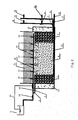
- FIGS 1 and 2 are schematically detailed structural views according to the present invention.
- a water head tank 1 discharges wastewater to be treated into a constructed wetland respectively by an upper water inlet pipe 2 and a top water distributing pipe 15.
- Substrates with different particle diameters are vertically filled and parallel to each other in the constructed wetland.
- the inside of the constructed wetland is divided into a left section 4, a middle section 5 and a right section 6.
- the substrates of the present invention may be zeolite, gravel, limestone, slag, active carbon and the like, and a combination of various substrates.
- the limestone is described simply by way of an example in the following context. Specifically, particle diameters of limestone substrates in the left and right sections 4, 6 are both 16-32 mm. A particle diameter of limestone substrate in the middle section 5 is 8-16 mm.
- the constructed wetland comprises the water inlet pipe 2 and the water distributing pipe 15, and a water outlet pipe 9 and a water collecting pipe 16 which are respectively controlled to introduce and discharge water by respective water inlet control valves and water outlet control valves.
- a top water inlet pipe 13 of the water head tank 1 and the left section 4 of the constructed wetland are connected with the water inlet pipe 2 by an upper water inlet valve 3, while the top water inlet pipe 13 is also connected with the water distributing pipe 15 by a top water inlet valve 14.
- the water outlet pipe 9 is mounted in a lower portion of the right section 6 on the other side of the constructed wetland.
- a main control valve 7and sub-control valves 8, 10, 11 are mounted on the water outlet pipe 9.
- the water collecting pipe 16 is mounted in a bottom layer of the constructed wetland.
- a main control valve 17 and sub-control valves 18, 19, 20 are mounted on the water collecting pipe 16.
- a water outlet of the water outlet pipe 9 and the water collecting pipe 16 is higher than a height of the bed of the constructed wetland.
- the highest sub-control valves 10 (19) of the sub-control valves 8, 10, 11 (18, 19, 20) must be located at a higher position than the height of the bed of the constructed wetland.
- the lowest sub-control valves 8 (18) of the sub-control valves 8, 10, 11 (18, 19, 20) are located at the bottom of the constructed wetland.
- the middle sub-control valves 11 (20) of the sub-control valves 8, 10, 11 (18, 19, 20) are located at a middle position of the limestone substrates.
- the sub-control valves are respectively designed to be located to have distances of 2.4m (the sub-control valves 10, 19), 1.3m (the sub-control valves 11, 20), 0.1m (the sub-control valves 8, 18) from the bottom layer of the bed in order to adjust water levels of the wetland cells, when the height of the substrates in the constructed wetland is 1.6-1.8m and the height of the bed is 2.2-2.5m.
- a barrier at periphery of the constructed wetland has a structure of a double wall 23 in which a uniformly mixed mixture of dejecta, bulrush and activated sludge is filled.
- a leakage-proof layer lies at a bottom inside of the double wall 23 to prevent a percolate generated by ferment of the mixture 23 of dejecta, bulrush and activated sludge from infiltrating underground to pollute ground water.
- the constructed wetland wastewater treatment equipment according to the present invention operates in the winter as described below.
- a top of the double wall 23 is opened as shown in FIG. 1 .
- the bulrush, dejecta and activated sludge are crushed by a crusher and then uniformly mixed.
- a water content of the mixture of bulrush, dejecta and activated sludge is adjusted by adding the water (this is known technology and not emphases of the present invention and thus is not described in detail).
- a height of the mixture is slightly higher than the height of the limestone substrates in the constructed wetland.
- the mixture leaves a height of 0.2 m at intervals of 1-2 m to form ventilation slots which have the same height as that of the mixture.
- the bulrush with a thickness of 0.1-0.2 m covers over the mixture to achieve a heat preservation effect.
- the main control valve 7 of the upper water inlet valve3 and the water outlet pipe 9 is closed and the top water inlet valve 14 is opened when the constructed wetland is a vertical down flow wetland.
- the top water inlet pipe 13 begins to uniformly distribute the water through the water distributing pipe 15. Meanwhile, the main control valve 17 and the sub-control valve 19 of the water collecting pipe16 at the bottom layer of the constructed wetland are opened so that the water level rises to 2.4m.
- the water collecting pipe 16 discharges the water (the water collecting pipe 16 of the present invention can be opened by a water aperture only at a position corresponding to the substrates in the middle section to enhance fluidity of the water flow in the constructed wetland) after water in the upper water level is froze (generally froze with a thickness of 0.4-0.6m).
- the sub-control valve 19 is then closed and the sub-control valve 18 is opened to rapidly lower the water level.
- the sub-control valve 18 is closed and the water outlet valve 20 is opened to discharge the water to the operating water level, thereby forming a heat preservation layer composed of an ice layer 21 and an air layer 22.
- top ventilation pipes 12 are opened to ensure concentration of dissolved oxygen under the ice.
- the top water inlet valve 14 and the main control valve 17 of the water collecting pipe 16 are closed, and the upper water inlet valve 3 and the main control valve 7 and the sub-control valve 10 of the water outlet pipe 9 are opened, when the constructed wetland is a horizontal flow.
- the water begins to enter the water inlet pipe 2 so that the water level rises to 2.4m.
- the water outlet pipe 9 discharges the water, the sub-control valve 10 is closed and the sub-control valve 8 is opened so as to rapidly lower the water level, after the upper water level is froze to 0.4-0.6m.
- the sub-control valve 8 When the operating water level of the wetland is reduced to 2.0m, the sub-control valve 8 is closed and the water outlet valve 11 is opened to discharge the water to the operating water level, thereby forming the heat preservation layer composed of the ice layer 21 and the air layer 22. At that time, the top ventilation pipes 12 are opened to ensure concentration of dissolved oxygen under the ice.
- the vertical flow and the horizontal flow can be mutually transformed.
- the transforming period depends on specific conditions. For example, the vertical flow operates in the early winter and the horizontal flow operates in the severe winter.
- the equipment of the present invention is started in the late autumn and continuously operates in the entire winter.
- the equipment collects products deriving from heat generation as an organic fertilizer used in a farmland after the heat generation is completed.
- the double wall 23 is under a sealed state in FIG. 2 .
- An anaerobic environment is formed inside the double wall 23 to facilitate to compatibility and metabolic heat generation of anaerobic microorganisms.
- the bulrush, dejecta and activated sludge are crushed by the crusher and then uniformly mixed.
- the water content of the mixture of bulrush, dejecta and activated sludge is adjusted by adding the water (this is known technology and not emphases of the present invention and thus is not described in detail).
- the height of the mixture is slightly higher than the height of the limestone substrates in the constructed wetland.
- the top of the double wall 23 is sealed and a gas transfer pipe 24 is arranged at the top thereof. A produced marsh gas enters the water head tank 1 through the gas transfer pipe 24 to thus ensure the anaerobic environment inside the double wall.
- the main control valve 7 of the upper water inlet valve3 and the water outlet pipe 9 is closed and the top water inlet valve 14 is opened when the constructed wetland is a vertical down flow wetland.
- the top water inlet pipe 13 begins to uniformly distribute the water through the water distributing pipe 15. Meanwhile, the main control valve 17 and the sub-control valve 19 of the water collecting pipe16 at the bottom layer of the constructed wetland are opened so that the water level rises to 2.4m.
- the water collecting pipe 16 discharges the water (the water collecting pipe 16 of the present invention can be opened by a water aperture only at a position corresponding to the substrates in the middle section to enhance fluidity of the water flow in the constructed wetland) after water in the upper water level is froze (generally froze with a thickness of 0.4-0.6m).
- the sub-control valve 19 is then closed and the sub-control valve 18 is opened to rapidly lower the water level.
- the sub-control valve 18 is closed and the water outlet valve 20 is opened to discharge the water to the operating water level, thereby forming the heat preservation layer composed of the ice layer 21 and the air layer 22.
- top ventilation pipes 12 are opened to ensure concentration of dissolved oxygen under the ice.
- the top water inlet valve 14 and the main control valve 17 of the water collecting pipe 16 are closed, and the upper water inlet valve 3 and the main control valve 7 and the sub-control valve 10 of the water outlet pipe 9 are opened, when the constructed wetland is a horizontal flow.
- the water begins to enter the water inlet pipe 2 so that the water level rises to 2.4m.
- the water outlet pipe 9 discharges the water, the sub-control valve 10 is closed and the sub-control valve 8 is opened so as to rapidly lower the water level, after the upper water level is froze to 0.4-0.6m.
- the sub-control valve 8 When the operating water level of the wetland is reduced to 2.0m, the sub-control valve 8 is closed and the water outlet valve 11 is opened to discharge the water to the operating water level, thereby forming the heat preservation layer composed of the ice layer 21 and the air layer 22. At that time, the top ventilation pipes 12 are opened to ensure concentration of dissolved oxygen under the ice.
- the vertical flow and the horizontal flow can be mutually transformed.
- the transforming period depends on specific conditions. For example, the vertical flow operates in the early winter and the horizontal flow operates in the severe winter.
- the equipment of the present invention is started in the late autumn and continuously operates in the entire winter.
- the equipment collects products deriving from heat generation as an organic fertilizer used in a farmland after the heat generation is completed.
Landscapes
- Life Sciences & Earth Sciences (AREA)
- Engineering & Computer Science (AREA)
- Hydrology & Water Resources (AREA)
- Botany (AREA)
- Biodiversity & Conservation Biology (AREA)
- Microbiology (AREA)
- Biotechnology (AREA)
- Environmental & Geological Engineering (AREA)
- Water Supply & Treatment (AREA)
- Chemical & Material Sciences (AREA)
- Organic Chemistry (AREA)
- Hydroponics (AREA)
- Biological Treatment Of Waste Water (AREA)
- Purification Treatments By Anaerobic Or Anaerobic And Aerobic Bacteria Or Animals (AREA)
Description
- The present invention relates to a heat preservation and temperature increasing equipment, and in particular, to a constructed wetland wastewater treatment equipment under low temperature for continuous operation.
- Environment, especially temperature, prominently influences removal efficiency of contaminants by constructed wetlands. Shihe Wang et al have found that a removal rate of TP by the constructed wetlands in winter is about 15% lower than a removal rate of TP by the constructed wetlands in summer. HuanShen et al have found in a demonstration project , in which scenic water body is purified by a subsurface flow type constructed wetland, that mean removal rates of TP and TN by the winter wetlands are 34% and 27% lower than those of TP and TN by the summer wetlands, respectively. Wallace et al consider that an over-low temperature not only affects an effect of contamination treatment by the constructed wetlands, but also may cause several disadvantageous effects such as freezing of a substrate layer, low concentration of the bed, pipe fracture and so on, thereby restricting application of the constructed wetlands in winter in cold regions. The current studies of wetland heat preservation drop behind since various methods cannot produce desirable effect.
- An object of the present invention is to provide a constructed wetland wastewater treatment equipment under low temperature for continuous operation to improve a high removal rate of nitrogen and phosphor, stabilization for a treatment effect and recycle of wastes. Further, the constructed wetland wastewater treatment equipment has a flow transformable function to ensure the constructed wetland to operate continuously and stably.
- To achieve the above object, the constructed wetland wastewater treatment equipment under low temperature for continuous operation according to the present invention mainly comprises:
- three-section substrates being vertically filled and parallel to each other in the constructed wetland, ventilation pipes being arranged in the substrates;
- a height of a bed of the constructed wetland being higher than a height of the substrates;
- a double wall used as a barrier at periphery of the constructed wetland, an organic substance being filled inside the double wall to perform a ferment heat generation, a top of the double wall being opened or sealed;
- a gas transfer pipe disposed at the top of the double wall when the top is sealed, the gas transfer pipe being connected to a water head tank of which a water pipe is connected to the constructed wetland;
- a water distributing pipe disposed at a top of the three-section substrates and a water collecting pipe disposed at a bottom of the three-section substrates, a water outlet of the water collecting pipe being higher than the height of the bed of the constructed wetland; and
- a water inlet pipe connected to an upper portion at one end of the three-section substrates and a water outlet pipe connected to a lower portion at the other end of the three-section substrates, a water outlet of the water outlet pipe being higher than the height of the bed of the constructed wetland;
- the constructed wetland wastewater treatment equipment being characterized in that the water distributing pipe and the water inlet pipe are respectively connected to the water head tank;
- the water inlet pipe and the water outlet pipe are closed when the water enters the water distributing pipe, the water is discharged through the highest water outlet of the water collecting pipe, and the water is adjusted to be discharged through a middle water outlet after a heat preservation layer composed of an ice layer and an air layer is formed;
- the water distributing pipe and the water collecting pipe at the bottom are closed when the water enters the water inlet pipe, the water is discharged through the highest water outlet of the water outlet pipe, and the water is adjusted to be discharged through the middle water outlet after the heat preservation layer composed of the ice layer and the air layer is formed; and
- the adjustment through the pipes for distributing the water is capable of making a mutual transform between a horizontal flow wetland and a vertical flow wetland.
- The substrates of the constructed wetland wastewater treatment equipment are a combination of one or more of zeolite, gravel, limestone, slag, active carbon.
- An upper section of substrates connected with the water inlet pipe is 10%-20% in length of a total length of the three-section substrates. A middle section of substrates is 70%-85% in length of the total length. A lower section of substrates connected with the water outlet pipe is 5%-10% in length of the total length.
- The height of the substrates is 1.6-1.8m, and the height of the bed is 2.2-2.5m.
- In the three-section substrates, particle diameters of the upper section of substrates connected with the water inlet pipe and the lower section of substrates connected with the water outlet pipe are both 16-32 mm, and a particle diameter of the middle section of substrates is 8-16 mm.
- The water distributing pipe and the water inlet pipe are connected to the water head tank by respective water inlet valves. The water collecting pipe and the water outlet pipe are provided with respective main control valves and respective sub-control valves at different heights.
- Each of the water collecting pipe and the water outlet pipe is provided with three sub-control valves which are respectively mounted at a position higher than the height of the bed of the constructed wetland, in the middle of the substrates, and at the bottom of the bed of the constructed wetland.
- The water distributing pipe and the water collecting pipe are both made of a PVC pipe with diameters from 100mm to 200mm. The water distributing pipe uniformly distributes the water, apertures are arranged on the water distributing pipe at an interval of 10-20cm and a diameter of each of the apertures is 1-3cm. The water collecting pipe is provided with water collecting apertures corresponding to the middle section of substrates. The water collecting apertures are arranged on the water collecting pipe at an interval of 5-10cm and a diameter of each of the water collecting apertures is 1-3cm.
- The upper layer of the constructed wetland is planted with emerged plants having strong decontamination.
- A leakage-proof layer is coated at the bottom inside of the double wall.
- The flow transformable wetland can mutually transform the horizontal flow wetland and the vertical flow wetland therebetween by adjusting distributing pipes based on the change of the ambient temperature. This overcomes disadvantages that dissolved oxygen of incoming water is low in the horizontal flow wetland in summer and a thermal loss is much in the vertical flow wetland in winter. Thereby, the operating mode of the wetland can be flexibly adjusted in winter. Further, the influence of the ambient temperature on the wetland is relieved by forming the heat preservation layer composed of the ice layer and the air layer, and the wetland can achieve a continuous heat preservation and temperature increase by a heat generated by metabolization of microorganism in the double wall, thereby ensuring the constructed wetland to continuously and stably operate under the low temperature. The flow transformable wetland has advantages of mutual transformation between the vertical flow wetland and the horizontal flow wetland, washing a matrix with water flowing in different directions, having a high organic substance decomposing effect and so on. Thus, the blocking problem can be relieved and even overcome. The present invention can be applied widely in large-scale, middle-scale and small-scale constructed wetlands to preserve temperature in winter. Therefore, the present invention has features of operating without pollution, easily operating, saving costs, having a low operating cost, achieving a good heat preservation effect, circulating resources, having a strong processing ability, stably operating and so on.
- The present invention effectively combines the horizontal flow wetland and the vertical flow wetland so that the operating mode of the wetland can be flexibly adjusted in winter. The water temperature in the wetland is substantially not affected by the ambient temperature by using the ice layer and an insulating air layer in a heat preservation manner insulating from the heat generated by metabolization of microorganism in the double wall, thereby ensuring the constructed wetland to endure the entire winter.
-
-
FIG. 1 is a schematically structural section view according to the present invention in which a double wall is an aerobic fermentation heat generation structure. -
FIG. 2 is a schematically structural section view according to the present invention in which a double wall is an anaerobic fermentation heat generation structure. - Exemplary embodiments of the present disclosure will be described hereinafter in detail with reference to the attached drawings, wherein the like reference numerals refer to the like elements.
- With reference to
FIGS 1 and2 , they are schematically detailed structural views according to the present invention. - It is noted that the terms used in the present invention, such as "left", "right", "upper", "down" and the like, employ the direction shown in
FIGS. 1 and2 as a reference basis, unless additionally stated. - A water head tank 1 discharges wastewater to be treated into a constructed wetland respectively by an upper
water inlet pipe 2 and a topwater distributing pipe 15. - Substrates with different particle diameters are vertically filled and parallel to each other in the constructed wetland. The inside of the constructed wetland is divided into a
left section 4, amiddle section 5 and aright section 6. The substrates of the present invention may be zeolite, gravel, limestone, slag, active carbon and the like, and a combination of various substrates. The limestone is described simply by way of an example in the following context. Specifically, particle diameters of limestone substrates in the left andright sections middle section 5 is 8-16 mm. - The constructed wetland comprises the
water inlet pipe 2 and thewater distributing pipe 15, and awater outlet pipe 9 and awater collecting pipe 16 which are respectively controlled to introduce and discharge water by respective water inlet control valves and water outlet control valves. Specifically, a topwater inlet pipe 13 of the water head tank 1 and theleft section 4 of the constructed wetland are connected with thewater inlet pipe 2 by an upperwater inlet valve 3, while the topwater inlet pipe 13 is also connected with thewater distributing pipe 15 by a topwater inlet valve 14. - The
water outlet pipe 9 is mounted in a lower portion of theright section 6 on the other side of the constructed wetland. A main control valve7and sub-control valves water outlet pipe 9. - The
water collecting pipe 16 is mounted in a bottom layer of the constructed wetland. Amain control valve 17 andsub-control valves water collecting pipe 16. - A water outlet of the
water outlet pipe 9 and thewater collecting pipe 16 is higher than a height of the bed of the constructed wetland. The highest sub-control valves 10 (19) of thesub-control valves sub-control valves sub-control valves sub-control valves 10, 19), 1.3m (thesub-control valves 11, 20), 0.1m (thesub-control valves 8, 18) from the bottom layer of the bed in order to adjust water levels of the wetland cells, when the height of the substrates in the constructed wetland is 1.6-1.8m and the height of the bed is 2.2-2.5m. - A barrier at periphery of the constructed wetland has a structure of a
double wall 23 in which a uniformly mixed mixture of dejecta, bulrush and activated sludge is filled. - A leakage-proof layer lies at a bottom inside of the
double wall 23 to prevent a percolate generated by ferment of themixture 23 of dejecta, bulrush and activated sludge from infiltrating underground to pollute ground water. - The constructed wetland wastewater treatment equipment according to the present invention operates in the winter as described below.
- A top of the
double wall 23 is opened as shown inFIG. 1 . The bulrush, dejecta and activated sludge are crushed by a crusher and then uniformly mixed. A water content of the mixture of bulrush, dejecta and activated sludge is adjusted by adding the water (this is known technology and not emphases of the present invention and thus is not described in detail). A height of the mixture is slightly higher than the height of the limestone substrates in the constructed wetland. The mixture leaves a height of 0.2 m at intervals of 1-2 m to form ventilation slots which have the same height as that of the mixture. The bulrush with a thickness of 0.1-0.2 m covers over the mixture to achieve a heat preservation effect. - The main control valve 7 of the upper water inlet valve3 and the
water outlet pipe 9 is closed and the topwater inlet valve 14 is opened when the constructed wetland is a vertical down flow wetland. The topwater inlet pipe 13 begins to uniformly distribute the water through thewater distributing pipe 15. Meanwhile, themain control valve 17 and thesub-control valve 19 of the water collecting pipe16 at the bottom layer of the constructed wetland are opened so that the water level rises to 2.4m. Thewater collecting pipe 16 discharges the water (thewater collecting pipe 16 of the present invention can be opened by a water aperture only at a position corresponding to the substrates in the middle section to enhance fluidity of the water flow in the constructed wetland) after water in the upper water level is froze (generally froze with a thickness of 0.4-0.6m). Thesub-control valve 19 is then closed and thesub-control valve 18 is opened to rapidly lower the water level. When the operating water level of the wetland is reduced to 2.0m, thesub-control valve 18 is closed and thewater outlet valve 20 is opened to discharge the water to the operating water level, thereby forming a heat preservation layer composed of anice layer 21 and anair layer 22. At that time,top ventilation pipes 12 are opened to ensure concentration of dissolved oxygen under the ice. - The top
water inlet valve 14 and themain control valve 17 of thewater collecting pipe 16 are closed, and the upperwater inlet valve 3 and the main control valve 7 and thesub-control valve 10 of thewater outlet pipe 9 are opened, when the constructed wetland is a horizontal flow. At that time, the water begins to enter thewater inlet pipe 2 so that the water level rises to 2.4m. Thewater outlet pipe 9 discharges the water, thesub-control valve 10 is closed and thesub-control valve 8 is opened so as to rapidly lower the water level, after the upper water level is froze to 0.4-0.6m. When the operating water level of the wetland is reduced to 2.0m, thesub-control valve 8 is closed and thewater outlet valve 11 is opened to discharge the water to the operating water level, thereby forming the heat preservation layer composed of theice layer 21 and theair layer 22. At that time, thetop ventilation pipes 12 are opened to ensure concentration of dissolved oxygen under the ice. - The vertical flow and the horizontal flow can be mutually transformed. The transforming period depends on specific conditions. For example, the vertical flow operates in the early winter and the horizontal flow operates in the severe winter.
- The equipment of the present invention is started in the late autumn and continuously operates in the entire winter. The equipment collects products deriving from heat generation as an organic fertilizer used in a farmland after the heat generation is completed.
- The
double wall 23 is under a sealed state inFIG. 2 . An anaerobic environment is formed inside thedouble wall 23 to facilitate to compatibility and metabolic heat generation of anaerobic microorganisms. - The bulrush, dejecta and activated sludge are crushed by the crusher and then uniformly mixed. The water content of the mixture of bulrush, dejecta and activated sludge is adjusted by adding the water (this is known technology and not emphases of the present invention and thus is not described in detail). The height of the mixture is slightly higher than the height of the limestone substrates in the constructed wetland. The top of the
double wall 23 is sealed and agas transfer pipe 24 is arranged at the top thereof. A produced marsh gas enters the water head tank 1 through thegas transfer pipe 24 to thus ensure the anaerobic environment inside the double wall. - The main control valve 7 of the upper water inlet valve3 and the
water outlet pipe 9 is closed and the topwater inlet valve 14 is opened when the constructed wetland is a vertical down flow wetland. The topwater inlet pipe 13 begins to uniformly distribute the water through thewater distributing pipe 15. Meanwhile, themain control valve 17 and thesub-control valve 19 of the water collecting pipe16 at the bottom layer of the constructed wetland are opened so that the water level rises to 2.4m. Thewater collecting pipe 16 discharges the water (thewater collecting pipe 16 of the present invention can be opened by a water aperture only at a position corresponding to the substrates in the middle section to enhance fluidity of the water flow in the constructed wetland) after water in the upper water level is froze (generally froze with a thickness of 0.4-0.6m). Thesub-control valve 19 is then closed and thesub-control valve 18 is opened to rapidly lower the water level. When the operating water level of the wetland is reduced to 2.0m, thesub-control valve 18 is closed and thewater outlet valve 20 is opened to discharge the water to the operating water level, thereby forming the heat preservation layer composed of theice layer 21 and theair layer 22. At that time,top ventilation pipes 12 are opened to ensure concentration of dissolved oxygen under the ice. - The top
water inlet valve 14 and themain control valve 17 of thewater collecting pipe 16 are closed, and the upperwater inlet valve 3 and the main control valve 7 and thesub-control valve 10 of thewater outlet pipe 9 are opened, when the constructed wetland is a horizontal flow. At that time, the water begins to enter thewater inlet pipe 2 so that the water level rises to 2.4m. Thewater outlet pipe 9 discharges the water, thesub-control valve 10 is closed and thesub-control valve 8 is opened so as to rapidly lower the water level, after the upper water level is froze to 0.4-0.6m. When the operating water level of the wetland is reduced to 2.0m, thesub-control valve 8 is closed and thewater outlet valve 11 is opened to discharge the water to the operating water level, thereby forming the heat preservation layer composed of theice layer 21 and theair layer 22. At that time, thetop ventilation pipes 12 are opened to ensure concentration of dissolved oxygen under the ice. - The vertical flow and the horizontal flow can be mutually transformed. The transforming period depends on specific conditions. For example, the vertical flow operates in the early winter and the horizontal flow operates in the severe winter.
- The equipment of the present invention is started in the late autumn and continuously operates in the entire winter. The equipment collects products deriving from heat generation as an organic fertilizer used in a farmland after the heat generation is completed.
Claims (10)
- A constructed wetland wastewater treatment equipment under a low temperature for continuous operation, comprising:three-section substrates (4, 5, 6) vertically filled and parallel to each other in the constructed wetland, ventilation pipes (12) being arranged in the substrates (4, 5, 6);a height of a bed of the constructed wetland being higher than a height of the substrates;a double wall (23) used as a barrier at periphery of the constructed wetland, an organic substance being filled inside the double wall (23) to perform a ferment heat generation, a top of the double wall (23) being opened or sealed;a gas transfer pipe (24) disposed at the top of the double wall (23) when the top is sealed by an ice layer (21), the gas transfer pipe (24) being connected to a water head tank (1) of which a water pipe (13) is connected to the constructed wetland;a water distributing pipe (15) disposed at a top of the three-section substrates (4, 5, 6) and a water collecting pipe (16) disposed at a bottom of the three-section substrates (4, 5, 6), a water outlet (19) of the water collecting pipe (16) being higher than the height of the bed of the constructed wetland; anda water inlet pipe (2) connected to an upper portion at one end of the three-section substrates (4, 5, 6) and a water outlet pipe (9) connected to a lower portion at the other end of the three-section substrates (4, 5, 6), a water outlet (10) of the water outlet pipe (9) being higher than the height of the bed of the constructed wetland;the constructed wetland wastewater treatment equipment being characterized in thatthe water distributing pipe (15) and the water inlet pipe (2) are respectively connected to the water head tank (1);the water inlet pipe (2) and the water outlet pipe (9) are closed when the water enters the water distributing pipe (15), the water is discharged through the highest water outlet (19) of the water collecting pipe (16), and the water is adjusted to be discharged through a middle water outlet (20) after a heat preservation layer composed of the ice layer (21) and an air layer is formed;the water distributing pipe (15) and the water collecting pipe (16) at the bottom are closed when the water enters the water inlet pipe (2), the water is discharged through the highest water outlet (10) of the water outlet pipe (9), and the water is adjusted to be discharged through the middle water outlet (11) after the heat preservation layer composed of the ice layer (21) and the air layer is formed; andthe adjustment of the pipes for distributing the water is capable of making a mutual transform between a horizontal flow wetland and a vertical flow wetland.
- The constructed wetland wastewater treatment equipment of claim 1, wherein the substrates are a combination of one or more of zeolite, gravel, limestone, slag, active carbon.
- The constructed wetland wastewater treatment equipment of claim 1, wherein an upper section of substrates connected with the water inlet pipe (2) is 10%-20% in length of a total length of the three-section substrates, a middle section of substrates is 70%-85% in length of the total length, and a lower section of substrates connected with the water outlet pipe is 5%-10% in length of the total length.
- The constructed wetland wastewater treatment equipment of claim 1, wherein the height of the substrates is 1.6-1.8m, and the height of the bed is 2.2-2.5m.
- The constructed wetland wastewater treatment equipment of claim 1, wherein in the three-section substrates (4, 5, 6), particle diameters of the upper section of substrates connected with the water inlet pipe and the lower section of substrates connected with the water outlet pipe are both 16-32 mm, and a particle diameter of the middle section of substrates is 8-16 mm.
- The constructed wetland wastewater treatment equipment of any of claims 1-5, wherein
the water distributing pipe (15) and the water inlet pipe (2) are connected to the water head tank (1) by respective water inlet valves (14, 3); and
the water collecting pipe (16) and the water outlet pipe (9) are provided with respective main control valves (17, 7) and respective sub-control valves (8, 10, 11 and 18, 19, 20) at different heights. - The constructed wetland wastewater treatment equipment of claim 6, wherein each of the water collecting pipe (16) and the water outlet pipe (9) is provided with three sub-control valves which are respectively mounted at a position higher (19, 10) than the height of the bed of the constructed wetland, in the middle (20, 11) of the substrates, and at the bottom (18, 8) of the bed of the constructed wetland.
- The constructed wetland wastewater treatment equipment of claim 1, 6 or 7, wherein the water distributing pipe (15) and the water collecting pipe (16) are both made of a PVC pipe with diameters from 100mm to 200mm, the water distributing pipe (15) uniformly distributes the water, apertures are arranged on the water distributing pipe (15) at an interval of 10-20cm, a diameter of each of the apertures is 1-3cm, the water collecting pipe is provided with water collecting apertures corresponding to the middle section of substrates (4, 5, 6), the water collecting apertures are arranged on the water collecting pipe (16) at an interval of 5-10cm and a diameter of each of the water collecting apertures is 1-3cm.
- The constructed wetland wastewater treatment equipment of claim 1, wherein the upper layer of the constructed wetland is planted with emerged plants having strong decontamination.
- The constructed wetland wastewater treatment equipment of claim 1, wherein a leakage-proof layer is coated at the bottom inside of the double wall (23).
Applications Claiming Priority (1)
| Application Number | Priority Date | Filing Date | Title |
|---|---|---|---|
| CN2012100042221A CN102633362B (en) | 2012-01-09 | 2012-01-09 | Artificial wetland sewage treatment device capable of running continuously at low temperature |
Publications (2)
| Publication Number | Publication Date |
|---|---|
| EP2612841A1 EP2612841A1 (en) | 2013-07-10 |
| EP2612841B1 true EP2612841B1 (en) | 2014-05-14 |
Family
ID=46229310
Family Applications (1)
| Application Number | Title | Priority Date | Filing Date |
|---|---|---|---|
| EP20120171182 Not-in-force EP2612841B1 (en) | 2012-01-09 | 2012-06-07 | Constructed wetland wastewater treatment equipment for continuous operation at low temperatures |
Country Status (3)
| Country | Link |
|---|---|
| US (1) | US8936725B2 (en) |
| EP (1) | EP2612841B1 (en) |
| CN (1) | CN102633362B (en) |
Families Citing this family (25)
| Publication number | Priority date | Publication date | Assignee | Title |
|---|---|---|---|---|
| CN102910787B (en) * | 2012-11-06 | 2014-03-19 | 重庆大学 | Garden-type rainwater processing and recycling integrated system in residential community |
| CN104031825B (en) * | 2013-03-07 | 2016-02-24 | 西北民族大学 | Anaerobic in low temperature marsh-gas fermentation tank |
| CN103332792B (en) * | 2013-07-19 | 2015-09-09 | 山东大学 | A kind of aerobic artificial wetland winter processing oil extraction-generated waste water is without support heat-insulation system |
| CN103936226B (en) * | 2014-04-04 | 2015-09-09 | 环境保护部南京环境科学研究所 | A kind of artificial wet land system and operation method thereof |
| FR3031516B1 (en) * | 2015-01-09 | 2018-09-14 | J Voisin | VERTICAL PERCOLATION PLANT FILTER TYPE WASTE TREATMENT DEVICE COMPRISING AN ACTIVE AERATION SYSTEM OF A SATURATED LOWER LAYER |
| FR3035103B1 (en) * | 2015-04-16 | 2024-01-26 | Sita Remediation | BIOFILTRATION DEVICE AND METHOD FOR THE TREATMENT OF WATER POLLUTED BY NITRATES AND/OR PERCHLORATES |
| CN105174430B (en) * | 2015-09-16 | 2019-03-26 | 中国科学院东北地理与农业生态研究所 | A kind of self-heating type cold operation Constructed Wetland For Purifying device and purification method |
| CN105461069B (en) * | 2015-12-02 | 2017-10-13 | 华北理工大学 | U-shape structure artificial swamp |
| CN106115927A (en) * | 2016-08-26 | 2016-11-16 | 北京顺景园林有限公司 | A kind of horizontal flow artificial wetland matrix structure system |
| CN206308130U (en) * | 2016-12-12 | 2017-07-07 | 深圳市山艺园林绿化有限公司 | A kind of artificial swamp resource recovery utilizes system |
| CN108569769B (en) * | 2017-08-28 | 2021-09-03 | 东北师范大学 | Vertical-flow constructed wetland biogas utilization system |
| CN107381787B (en) * | 2017-09-04 | 2023-05-16 | 北京东方园林环境股份有限公司 | Constructed wetland system suitable for low-temperature environment |
| CN107522287B (en) * | 2017-09-04 | 2020-01-21 | 北京东方园林环境股份有限公司 | Water purification method of constructed wetland system |
| CN108033566B (en) * | 2017-12-13 | 2018-12-07 | 中国科学院地理科学与资源研究所 | One heavy metal species prevention and control system and the heavy metal preventing control method for using it |
| CN109111017A (en) * | 2018-08-03 | 2019-01-01 | 西安科技大学 | A kind of rural sewage ecological circular treatment micro-loop system and its working method |
| CN109019863B (en) * | 2018-09-14 | 2021-08-31 | 浙江中誉生态环境科技有限公司 | Artificial wetland system and operation method |
| CN109179679A (en) * | 2018-10-30 | 2019-01-11 | 中国科学院水生生物研究所 | It is a kind of can alternate run artificial swamp and its workflow |
| CN109851175B (en) * | 2019-03-21 | 2023-10-27 | 金陵科技学院 | An ecological purification artificial canal island system |
| CN111056640A (en) * | 2019-12-17 | 2020-04-24 | 深圳市碧园环保技术有限公司 | A constructed wetland structure suitable for cold regions |
| CN111732198B (en) * | 2020-05-15 | 2024-06-04 | 中国矿业大学 | Multifunctional artificial wetland integrated simulation experiment device |
| CN112125412B (en) * | 2020-10-22 | 2025-01-28 | 中国科学院生态环境研究中心 | Water regulating pond system for reoxygenation, anti-clogging and/or anti-freezing of subsurface constructed wetlands |
| CN112551824B (en) * | 2020-12-23 | 2021-11-26 | 广东省水文局韶关水文分局 | Vertical subsurface flow type constructed wetland device and method for sludge treatment |
| CN112624516A (en) * | 2020-12-25 | 2021-04-09 | 广东中然水务科技有限公司 | Automatic purification and discharge system and device applied to rural sewage treatment |
| CN113200608A (en) * | 2021-05-17 | 2021-08-03 | 江苏大学 | Method for treating organic matters in artificial wetland |
| CN117658389B (en) * | 2024-01-29 | 2024-04-26 | 成都嘉德数源环保科技有限公司 | Highland high-cold sewage treatment method |
Family Cites Families (7)
| Publication number | Priority date | Publication date | Assignee | Title |
|---|---|---|---|---|
| JP4199075B2 (en) * | 2003-09-04 | 2008-12-17 | 株式会社奥村組 | Water purification facility |
| US7674378B2 (en) * | 2006-12-19 | 2010-03-09 | Modular Wetland Systems, Inc. | Wetland water treatment system |
| US8252182B1 (en) * | 2008-09-11 | 2012-08-28 | University Of Central Florida Research Foundation, Inc. | Subsurface upflow wetland system for nutrient and pathogen removal in wastewater treatment systems |
| CN102145956B (en) * | 2010-02-04 | 2013-04-03 | 山东大学 | Self-made heat bow-shaped shed rapid infiltration system |
| CN201882979U (en) * | 2010-12-15 | 2011-06-29 | 武汉昌宝环保工程有限公司 | Artificial double water inlet wetland device for circulating and reinforcing nitrogen removal |
| CN201952328U (en) * | 2011-01-10 | 2011-08-31 | 山东大学 | Landscape inverted biological quick filtration device |
| CN102260021A (en) * | 2011-06-01 | 2011-11-30 | 同济大学 | Process and device for deep denitrogenation of domestic wastewater without additional carbon source |
-
2012
- 2012-01-09 CN CN2012100042221A patent/CN102633362B/en not_active Expired - Fee Related
- 2012-06-07 EP EP20120171182 patent/EP2612841B1/en not_active Not-in-force
- 2012-06-07 US US13/491,124 patent/US8936725B2/en active Active
Also Published As
| Publication number | Publication date |
|---|---|
| EP2612841A1 (en) | 2013-07-10 |
| US20130175215A1 (en) | 2013-07-11 |
| US8936725B2 (en) | 2015-01-20 |
| CN102633362A (en) | 2012-08-15 |
| CN102633362B (en) | 2013-10-16 |
Similar Documents
| Publication | Publication Date | Title |
|---|---|---|
| US8936725B2 (en) | Engineered wetland device of continuous operation for wastewater treatment under low temperature | |
| CN103936226B (en) | A kind of artificial wet land system and operation method thereof | |
| CN105645677B (en) | A kind of level stream and vertical current integrated constructed wetland and its operation method | |
| CN102531185B (en) | Variable flow constructed wetland provided with winter temperature maintaining and raising device | |
| CN108558141B (en) | Biological-ecological combined treatment system and treatment method for rural sewage under low temperature conditions | |
| CN101880089A (en) | A baffle type artificial wetland device for treating low-concentration non-point source pollution | |
| CN103449608B (en) | Novel vertical flow automatic aeration annular artificial wetland system | |
| CN104828951B (en) | A kind of artificial wet land reinforced carbon nitrogen of ecological regulation and control type synchronously removes system | |
| CN102276110B (en) | Method for remedying micro-polluted water body and subsurface flow artificial wetland system | |
| CN106830545A (en) | A kind of combination type wetland drop water aeration sewage disposal system and method | |
| CN109607801B (en) | Composite constructed wetland sewage treatment system for denitrification and dephosphorization | |
| CN102557262B (en) | Winter heat-preserving device for constructed wetland sewage treatment system | |
| CN101786717B (en) | Excess sludge reduction bioreactor with variable aeration and worm attachment oblique plate | |
| CN206692517U (en) | A kind of integrated combination wetland domestic sewage processing system | |
| CN206692417U (en) | A kind of three-dimensional composite constructed wetland system | |
| CN102351381A (en) | Device and method for treating sulfate wastewater | |
| CN107512775A (en) | A kind of temperature adjusting method of artificial wet land system and strengthened artificial wet land system hypothermia operation | |
| CN105174468B (en) | A kind of cellular-type composite stereo artificial wet land system and sewage water treatment method | |
| CN103864214B (en) | A kind of buried sewage ecological treatment system | |
| CN101134623A (en) | Method for comprehensive treatment of polluted water by inhibiting growth of blue algae | |
| CN103086505A (en) | Device and method for strengthening impact resisting load of anaerobic treatment wastewater | |
| CN116354511A (en) | Nitrogen and phosphorus removal wetland system and its application | |
| CN110902937A (en) | Small self-supporting rural sewage treatment system and sewage treatment method | |
| CN105198080A (en) | Anaerobic particle sludge rapid culture method suitable for oil refining and chemical engineering wastewater treatment | |
| CN102586095B (en) | Gas stripping convective circulation anaerobic digestion reactor |
Legal Events
| Date | Code | Title | Description |
|---|---|---|---|
| PUAI | Public reference made under article 153(3) epc to a published international application that has entered the european phase |
Free format text: ORIGINAL CODE: 0009012 |
|
| 17P | Request for examination filed |
Effective date: 20120607 |
|
| AK | Designated contracting states |
Kind code of ref document: A1 Designated state(s): AL AT BE BG CH CY CZ DE DK EE ES FI FR GB GR HR HU IE IS IT LI LT LU LV MC MK MT NL NO PL PT RO RS SE SI SK SM TR |
|
| AX | Request for extension of the european patent |
Extension state: BA ME |
|
| RIC1 | Information provided on ipc code assigned before grant |
Ipc: C02F 3/06 20060101ALN20131121BHEP Ipc: C02F 3/32 20060101AFI20131121BHEP |
|
| GRAP | Despatch of communication of intention to grant a patent |
Free format text: ORIGINAL CODE: EPIDOSNIGR1 |
|
| GRAS | Grant fee paid |
Free format text: ORIGINAL CODE: EPIDOSNIGR3 |
|
| INTG | Intention to grant announced |
Effective date: 20140225 |
|
| GRAA | (expected) grant |
Free format text: ORIGINAL CODE: 0009210 |
|
| AK | Designated contracting states |
Kind code of ref document: B1 Designated state(s): AL AT BE BG CH CY CZ DE DK EE ES FI FR GB GR HR HU IE IS IT LI LT LU LV MC MK MT NL NO PL PT RO RS SE SI SK SM TR |
|
| REG | Reference to a national code |
Ref country code: GB Ref legal event code: FG4D |
|
| REG | Reference to a national code |
Ref country code: AT Ref legal event code: REF Ref document number: 668171 Country of ref document: AT Kind code of ref document: T Effective date: 20140615 |
|
| REG | Reference to a national code |
Ref country code: IE Ref legal event code: FG4D |
|
| REG | Reference to a national code |
Ref country code: DE Ref legal event code: R096 Ref document number: 602012001705 Country of ref document: DE Effective date: 20140626 |
|
| REG | Reference to a national code |
Ref country code: AT Ref legal event code: MK05 Ref document number: 668171 Country of ref document: AT Kind code of ref document: T Effective date: 20140514 Ref country code: NL Ref legal event code: VDEP Effective date: 20140514 |
|
| REG | Reference to a national code |
Ref country code: LT Ref legal event code: MG4D |
|
| PG25 | Lapsed in a contracting state [announced via postgrant information from national office to epo] |
Ref country code: FI Free format text: LAPSE BECAUSE OF FAILURE TO SUBMIT A TRANSLATION OF THE DESCRIPTION OR TO PAY THE FEE WITHIN THE PRESCRIBED TIME-LIMIT Effective date: 20140514 Ref country code: CY Free format text: LAPSE BECAUSE OF FAILURE TO SUBMIT A TRANSLATION OF THE DESCRIPTION OR TO PAY THE FEE WITHIN THE PRESCRIBED TIME-LIMIT Effective date: 20140514 Ref country code: LT Free format text: LAPSE BECAUSE OF FAILURE TO SUBMIT A TRANSLATION OF THE DESCRIPTION OR TO PAY THE FEE WITHIN THE PRESCRIBED TIME-LIMIT Effective date: 20140514 Ref country code: IS Free format text: LAPSE BECAUSE OF FAILURE TO SUBMIT A TRANSLATION OF THE DESCRIPTION OR TO PAY THE FEE WITHIN THE PRESCRIBED TIME-LIMIT Effective date: 20140914 Ref country code: NO Free format text: LAPSE BECAUSE OF FAILURE TO SUBMIT A TRANSLATION OF THE DESCRIPTION OR TO PAY THE FEE WITHIN THE PRESCRIBED TIME-LIMIT Effective date: 20140814 Ref country code: GR Free format text: LAPSE BECAUSE OF FAILURE TO SUBMIT A TRANSLATION OF THE DESCRIPTION OR TO PAY THE FEE WITHIN THE PRESCRIBED TIME-LIMIT Effective date: 20140815 |
|
| PG25 | Lapsed in a contracting state [announced via postgrant information from national office to epo] |
Ref country code: PL Free format text: LAPSE BECAUSE OF FAILURE TO SUBMIT A TRANSLATION OF THE DESCRIPTION OR TO PAY THE FEE WITHIN THE PRESCRIBED TIME-LIMIT Effective date: 20140514 Ref country code: AT Free format text: LAPSE BECAUSE OF FAILURE TO SUBMIT A TRANSLATION OF THE DESCRIPTION OR TO PAY THE FEE WITHIN THE PRESCRIBED TIME-LIMIT Effective date: 20140514 Ref country code: LV Free format text: LAPSE BECAUSE OF FAILURE TO SUBMIT A TRANSLATION OF THE DESCRIPTION OR TO PAY THE FEE WITHIN THE PRESCRIBED TIME-LIMIT Effective date: 20140514 Ref country code: HR Free format text: LAPSE BECAUSE OF FAILURE TO SUBMIT A TRANSLATION OF THE DESCRIPTION OR TO PAY THE FEE WITHIN THE PRESCRIBED TIME-LIMIT Effective date: 20140514 Ref country code: SE Free format text: LAPSE BECAUSE OF FAILURE TO SUBMIT A TRANSLATION OF THE DESCRIPTION OR TO PAY THE FEE WITHIN THE PRESCRIBED TIME-LIMIT Effective date: 20140514 Ref country code: ES Free format text: LAPSE BECAUSE OF FAILURE TO SUBMIT A TRANSLATION OF THE DESCRIPTION OR TO PAY THE FEE WITHIN THE PRESCRIBED TIME-LIMIT Effective date: 20140514 Ref country code: RS Free format text: LAPSE BECAUSE OF FAILURE TO SUBMIT A TRANSLATION OF THE DESCRIPTION OR TO PAY THE FEE WITHIN THE PRESCRIBED TIME-LIMIT Effective date: 20140514 |
|
| PG25 | Lapsed in a contracting state [announced via postgrant information from national office to epo] |
Ref country code: PT Free format text: LAPSE BECAUSE OF FAILURE TO SUBMIT A TRANSLATION OF THE DESCRIPTION OR TO PAY THE FEE WITHIN THE PRESCRIBED TIME-LIMIT Effective date: 20140915 |
|
| REG | Reference to a national code |
Ref country code: DE Ref legal event code: R119 Ref document number: 602012001705 Country of ref document: DE |
|
| PG25 | Lapsed in a contracting state [announced via postgrant information from national office to epo] |
Ref country code: EE Free format text: LAPSE BECAUSE OF FAILURE TO SUBMIT A TRANSLATION OF THE DESCRIPTION OR TO PAY THE FEE WITHIN THE PRESCRIBED TIME-LIMIT Effective date: 20140514 Ref country code: CZ Free format text: LAPSE BECAUSE OF FAILURE TO SUBMIT A TRANSLATION OF THE DESCRIPTION OR TO PAY THE FEE WITHIN THE PRESCRIBED TIME-LIMIT Effective date: 20140514 Ref country code: SK Free format text: LAPSE BECAUSE OF FAILURE TO SUBMIT A TRANSLATION OF THE DESCRIPTION OR TO PAY THE FEE WITHIN THE PRESCRIBED TIME-LIMIT Effective date: 20140514 Ref country code: BE Free format text: LAPSE BECAUSE OF FAILURE TO SUBMIT A TRANSLATION OF THE DESCRIPTION OR TO PAY THE FEE WITHIN THE PRESCRIBED TIME-LIMIT Effective date: 20140514 Ref country code: DK Free format text: LAPSE BECAUSE OF FAILURE TO SUBMIT A TRANSLATION OF THE DESCRIPTION OR TO PAY THE FEE WITHIN THE PRESCRIBED TIME-LIMIT Effective date: 20140514 Ref country code: RO Free format text: LAPSE BECAUSE OF FAILURE TO SUBMIT A TRANSLATION OF THE DESCRIPTION OR TO PAY THE FEE WITHIN THE PRESCRIBED TIME-LIMIT Effective date: 20140514 |
|
| PG25 | Lapsed in a contracting state [announced via postgrant information from national office to epo] |
Ref country code: NL Free format text: LAPSE BECAUSE OF FAILURE TO SUBMIT A TRANSLATION OF THE DESCRIPTION OR TO PAY THE FEE WITHIN THE PRESCRIBED TIME-LIMIT Effective date: 20140514 |
|
| PLBE | No opposition filed within time limit |
Free format text: ORIGINAL CODE: 0009261 |
|
| STAA | Information on the status of an ep patent application or granted ep patent |
Free format text: STATUS: NO OPPOSITION FILED WITHIN TIME LIMIT |
|
| REG | Reference to a national code |
Ref country code: IE Ref legal event code: MM4A |
|
| REG | Reference to a national code |
Ref country code: DE Ref legal event code: R119 Ref document number: 602012001705 Country of ref document: DE Effective date: 20150101 |
|
| REG | Reference to a national code |
Ref country code: FR Ref legal event code: ST Effective date: 20150227 |
|
| 26N | No opposition filed |
Effective date: 20150217 |
|
| PG25 | Lapsed in a contracting state [announced via postgrant information from national office to epo] |
Ref country code: DE Free format text: LAPSE BECAUSE OF NON-PAYMENT OF DUE FEES Effective date: 20150101 Ref country code: IT Free format text: LAPSE BECAUSE OF FAILURE TO SUBMIT A TRANSLATION OF THE DESCRIPTION OR TO PAY THE FEE WITHIN THE PRESCRIBED TIME-LIMIT Effective date: 20140514 Ref country code: IE Free format text: LAPSE BECAUSE OF NON-PAYMENT OF DUE FEES Effective date: 20140607 |
|
| PG25 | Lapsed in a contracting state [announced via postgrant information from national office to epo] |
Ref country code: FR Free format text: LAPSE BECAUSE OF NON-PAYMENT OF DUE FEES Effective date: 20140715 |
|
| PG25 | Lapsed in a contracting state [announced via postgrant information from national office to epo] |
Ref country code: SI Free format text: LAPSE BECAUSE OF FAILURE TO SUBMIT A TRANSLATION OF THE DESCRIPTION OR TO PAY THE FEE WITHIN THE PRESCRIBED TIME-LIMIT Effective date: 20140514 |
|
| REG | Reference to a national code |
Ref country code: CH Ref legal event code: PL |
|
| PG25 | Lapsed in a contracting state [announced via postgrant information from national office to epo] |
Ref country code: MT Free format text: LAPSE BECAUSE OF FAILURE TO SUBMIT A TRANSLATION OF THE DESCRIPTION OR TO PAY THE FEE WITHIN THE PRESCRIBED TIME-LIMIT Effective date: 20140514 |
|
| PG25 | Lapsed in a contracting state [announced via postgrant information from national office to epo] |
Ref country code: SM Free format text: LAPSE BECAUSE OF FAILURE TO SUBMIT A TRANSLATION OF THE DESCRIPTION OR TO PAY THE FEE WITHIN THE PRESCRIBED TIME-LIMIT Effective date: 20140514 Ref country code: CH Free format text: LAPSE BECAUSE OF NON-PAYMENT OF DUE FEES Effective date: 20150630 Ref country code: LI Free format text: LAPSE BECAUSE OF NON-PAYMENT OF DUE FEES Effective date: 20150630 Ref country code: MC Free format text: LAPSE BECAUSE OF FAILURE TO SUBMIT A TRANSLATION OF THE DESCRIPTION OR TO PAY THE FEE WITHIN THE PRESCRIBED TIME-LIMIT Effective date: 20140514 |
|
| PG25 | Lapsed in a contracting state [announced via postgrant information from national office to epo] |
Ref country code: BG Free format text: LAPSE BECAUSE OF FAILURE TO SUBMIT A TRANSLATION OF THE DESCRIPTION OR TO PAY THE FEE WITHIN THE PRESCRIBED TIME-LIMIT Effective date: 20140514 |
|
| PG25 | Lapsed in a contracting state [announced via postgrant information from national office to epo] |
Ref country code: LU Free format text: LAPSE BECAUSE OF NON-PAYMENT OF DUE FEES Effective date: 20140607 Ref country code: TR Free format text: LAPSE BECAUSE OF FAILURE TO SUBMIT A TRANSLATION OF THE DESCRIPTION OR TO PAY THE FEE WITHIN THE PRESCRIBED TIME-LIMIT Effective date: 20140514 Ref country code: HU Free format text: LAPSE BECAUSE OF FAILURE TO SUBMIT A TRANSLATION OF THE DESCRIPTION OR TO PAY THE FEE WITHIN THE PRESCRIBED TIME-LIMIT; INVALID AB INITIO Effective date: 20120607 |
|
| GBPC | Gb: european patent ceased through non-payment of renewal fee |
Effective date: 20160607 |
|
| PG25 | Lapsed in a contracting state [announced via postgrant information from national office to epo] |
Ref country code: GB Free format text: LAPSE BECAUSE OF NON-PAYMENT OF DUE FEES Effective date: 20160607 |
|
| PG25 | Lapsed in a contracting state [announced via postgrant information from national office to epo] |
Ref country code: MK Free format text: LAPSE BECAUSE OF FAILURE TO SUBMIT A TRANSLATION OF THE DESCRIPTION OR TO PAY THE FEE WITHIN THE PRESCRIBED TIME-LIMIT Effective date: 20140514 |
|
| PG25 | Lapsed in a contracting state [announced via postgrant information from national office to epo] |
Ref country code: AL Free format text: LAPSE BECAUSE OF FAILURE TO SUBMIT A TRANSLATION OF THE DESCRIPTION OR TO PAY THE FEE WITHIN THE PRESCRIBED TIME-LIMIT Effective date: 20140514 |