EP2612830A2 - Image forming apparatus - Google Patents
Image forming apparatus Download PDFInfo
- Publication number
- EP2612830A2 EP2612830A2 EP12182392.6A EP12182392A EP2612830A2 EP 2612830 A2 EP2612830 A2 EP 2612830A2 EP 12182392 A EP12182392 A EP 12182392A EP 2612830 A2 EP2612830 A2 EP 2612830A2
- Authority
- EP
- European Patent Office
- Prior art keywords
- unit
- main body
- plate
- paper feeding
- feeding device
- Prior art date
- Legal status (The legal status is an assumption and is not a legal conclusion. Google has not performed a legal analysis and makes no representation as to the accuracy of the status listed.)
- Granted
Links
Images



Classifications
-
- G—PHYSICS
- G03—PHOTOGRAPHY; CINEMATOGRAPHY; ANALOGOUS TECHNIQUES USING WAVES OTHER THAN OPTICAL WAVES; ELECTROGRAPHY; HOLOGRAPHY
- G03G—ELECTROGRAPHY; ELECTROPHOTOGRAPHY; MAGNETOGRAPHY
- G03G15/00—Apparatus for electrographic processes using a charge pattern
-
- G—PHYSICS
- G03—PHOTOGRAPHY; CINEMATOGRAPHY; ANALOGOUS TECHNIQUES USING WAVES OTHER THAN OPTICAL WAVES; ELECTROGRAPHY; HOLOGRAPHY
- G03G—ELECTROGRAPHY; ELECTROPHOTOGRAPHY; MAGNETOGRAPHY
- G03G15/00—Apparatus for electrographic processes using a charge pattern
- G03G15/65—Apparatus which relate to the handling of copy material
- G03G15/6502—Supplying of sheet copy material; Cassettes therefor
- G03G15/6511—Feeding devices for picking up or separation of copy sheets
-
- B—PERFORMING OPERATIONS; TRANSPORTING
- B41—PRINTING; LINING MACHINES; TYPEWRITERS; STAMPS
- B41J—TYPEWRITERS; SELECTIVE PRINTING MECHANISMS, i.e. MECHANISMS PRINTING OTHERWISE THAN FROM A FORME; CORRECTION OF TYPOGRAPHICAL ERRORS
- B41J13/00—Devices or arrangements of selective printing mechanisms, e.g. ink-jet printers or thermal printers, specially adapted for supporting or handling copy material in short lengths, e.g. sheets
- B41J13/10—Sheet holders, retainers, movable guides, or stationary guides
-
- B—PERFORMING OPERATIONS; TRANSPORTING
- B41—PRINTING; LINING MACHINES; TYPEWRITERS; STAMPS
- B41J—TYPEWRITERS; SELECTIVE PRINTING MECHANISMS, i.e. MECHANISMS PRINTING OTHERWISE THAN FROM A FORME; CORRECTION OF TYPOGRAPHICAL ERRORS
- B41J13/00—Devices or arrangements of selective printing mechanisms, e.g. ink-jet printers or thermal printers, specially adapted for supporting or handling copy material in short lengths, e.g. sheets
- B41J13/10—Sheet holders, retainers, movable guides, or stationary guides
- B41J13/103—Sheet holders, retainers, movable guides, or stationary guides for the sheet feeding section
-
- B—PERFORMING OPERATIONS; TRANSPORTING
- B65—CONVEYING; PACKING; STORING; HANDLING THIN OR FILAMENTARY MATERIAL
- B65H—HANDLING THIN OR FILAMENTARY MATERIAL, e.g. SHEETS, WEBS, CABLES
- B65H1/00—Supports or magazines for piles from which articles are to be separated
- B65H1/08—Supports or magazines for piles from which articles are to be separated with means for advancing the articles to present the articles to the separating device
- B65H1/12—Supports or magazines for piles from which articles are to be separated with means for advancing the articles to present the articles to the separating device comprising spring
-
- B—PERFORMING OPERATIONS; TRANSPORTING
- B65—CONVEYING; PACKING; STORING; HANDLING THIN OR FILAMENTARY MATERIAL
- B65H—HANDLING THIN OR FILAMENTARY MATERIAL, e.g. SHEETS, WEBS, CABLES
- B65H1/00—Supports or magazines for piles from which articles are to be separated
- B65H1/26—Supports or magazines for piles from which articles are to be separated with auxiliary supports to facilitate introduction or renewal of the pile
- B65H1/266—Support fully or partially removable from the handling machine, e.g. cassette, drawer
-
- B—PERFORMING OPERATIONS; TRANSPORTING
- B65—CONVEYING; PACKING; STORING; HANDLING THIN OR FILAMENTARY MATERIAL
- B65H—HANDLING THIN OR FILAMENTARY MATERIAL, e.g. SHEETS, WEBS, CABLES
- B65H2402/00—Constructional details of the handling apparatus
- B65H2402/50—Machine elements
- B65H2402/51—Joints, e.g. riveted or magnetic joints
-
- B—PERFORMING OPERATIONS; TRANSPORTING
- B65—CONVEYING; PACKING; STORING; HANDLING THIN OR FILAMENTARY MATERIAL
- B65H—HANDLING THIN OR FILAMENTARY MATERIAL, e.g. SHEETS, WEBS, CABLES
- B65H2402/00—Constructional details of the handling apparatus
- B65H2402/60—Coupling, adapter or locking means
-
- B—PERFORMING OPERATIONS; TRANSPORTING
- B65—CONVEYING; PACKING; STORING; HANDLING THIN OR FILAMENTARY MATERIAL
- B65H—HANDLING THIN OR FILAMENTARY MATERIAL, e.g. SHEETS, WEBS, CABLES
- B65H2405/00—Parts for holding the handled material
- B65H2405/10—Cassettes, holders, bins, decks, trays, supports or magazines for sheets stacked substantially horizontally
- B65H2405/11—Parts and details thereof
- B65H2405/111—Bottom
- B65H2405/1117—Bottom pivotable, e.g. around an axis perpendicular to transport direction, e.g. arranged at rear side of sheet support
-
- B—PERFORMING OPERATIONS; TRANSPORTING
- B65—CONVEYING; PACKING; STORING; HANDLING THIN OR FILAMENTARY MATERIAL
- B65H—HANDLING THIN OR FILAMENTARY MATERIAL, e.g. SHEETS, WEBS, CABLES
- B65H2601/00—Problem to be solved or advantage achieved
- B65H2601/20—Avoiding or preventing undesirable effects
- B65H2601/25—Damages to handled material
- B65H2601/255—Jam
-
- B—PERFORMING OPERATIONS; TRANSPORTING
- B65—CONVEYING; PACKING; STORING; HANDLING THIN OR FILAMENTARY MATERIAL
- B65H—HANDLING THIN OR FILAMENTARY MATERIAL, e.g. SHEETS, WEBS, CABLES
- B65H2801/00—Application field
- B65H2801/03—Image reproduction devices
- B65H2801/06—Office-type machines, e.g. photocopiers
Definitions
- the present invention relates to an image forming apparatus, and more particularly, to an image forming apparatus with an improved paper feeding device for feeding a recording medium.
- Image forming apparatuses are generally used to form an image on a recording medium. Examples thereof include printers, copy machines, facsimile machines, and all-in-one devices implemented by combining functions of a printer, a copy machine, and a facsimile machine.
- Such image forming apparatuses generally include a paper feeding device for feeding a recording medium to a printing unit included in the image forming apparatus.
- the recording medium accommodated in the paper feeding device is picked up by a pickup roller and fed to the printing unit along a predetermined path.
- the pickup roller picks up the recording medium by using a frictional force against the recording medium.
- a frictional force sufficient for the pick-up requires a predetermined pressure relationship between the recording medium and the pickup roller.
- a knock-up plate for pressing the recording medium against the pickup roller is used.
- the guide unit has a fixed structure and provides a constant slope regardless of the remaining number of recording media accommodated in the paper feeding device, a gap between the guide unit and the knock-up plate varies according to the remaining number of recording media.
- the gap between the guide unit and the knock-up plate is very large, and thus, the knock-up plate cannot be immediately lowered even when the paper feeding device is withdrawn and the pressure relationship is temporarily maintained, thereby resulting in a jam.
- One or more embodiments of the present invention relate to an image forming apparatus capable of preventing a jam in a withdrawal of a paper feeding device regardless of the remaining number of recording media.
- an image forming apparatus including: a main body including a printing unit for printing an image on a recording medium and a pickup roller for picking up the recording medium; a paper feeding device, which includes an elevatable knock-up plate on which recording media are stackable and a pressure member for elastically pressing the knock-up plate towards the pickup roller and is removably inserted into the main body; and a variable guide unit, which is supported by the main body, is fixed in a slope state to lower the knock-up plate in a direction against the pickup roller when the paper feeding device is withdrawn from the main body, and moves to maintain a contact state with the knock-up plate due to a rising state of the knock-up plate in a state in which the paper feeding device is inserted into the main body.
- the variable guide unit may include: a variable guide member, which has a slope unit downwardly sloped in a withdrawal direction to lower the knock-up plate in a direction against the pickup roller by contacting with a contact unit of the knock-up plate when the paper feeding device is withdrawn from the main body and is supported by the main body for the slope unit to maintain a contact state with the contact unit due to a rising state of the knock-up plate; and a fixing member, which is supported by the main body, moves to a fixing position for fixing the variable guide member to be coupled with the variable guide member when the paper feeding device is withdrawn from the main body, and moves to a release position for releasing the variable guide member to be decoupled from the variable guide member when the paper feeding device is inserted into the main body.
- the slope unit may include a release unit for allowing the contact unit to be released from the slope unit after the knock-up plate is lowered.
- the contact unit may be formed to protrude from the knock-up plate, and the release unit may be formed as a groove in the slope unit so that the contact unit passes through the release unit.
- the image forming apparatus may further include a first elastic member for providing an elastic force to the variable guide member in a direction in which the slope unit contacts the contact unit.
- the elastic force of the first elastic member may be less than a pressure of the pressure member.
- the image forming apparatus may further include: a second elastic member for providing an elastic force in a direction in which the fixing member moves to the fixing position; and a switching member for switching to the release position in contact with the fixing member when the paper feeding device is inserted into the main body.
- the switching member may maintain the fixing member at the release position by maintaining a contact state with the fixing member in a state in which the insertion of the paper feeding device is completed.
- the variable guide unit may include a first coupling unit
- the fixing member may include a second coupling unit having a shape complementary to the first coupling unit, the second coupling unit being coupled with the first coupling unit when the fixing member is located at the fixing position.
- the first and second coupling units may have gear shapes gearing with each other.
- a variable guide unit rotatably installed in a main body of a printing apparatus including: a paper feeding device with a pickup roller and a knock-up plate, the variable guide unit including: a variable guide member including a slope unit downwardly sloped in a withdrawal direction to lower the knock-up plate in a direction away from the pickup roller by contacting a contact unit of the knock-up plate when the paper feeding device is withdrawn from the main body and is supported by the main body for the slope unit to maintain a contact state with the contact unit due to a rising state of the knock-up plate; and a fixing member, which is supported by the main body, to move to a fixing position for fixing the variable guide member by coupling with the variable guide member when the paper feeding device is withdrawn from the main body and to move to a release position for releasing the variable guide member by decoupling from the variable guide member when the paper feeding device is inserted into the main body.
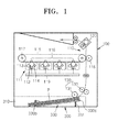
- FIG. 1 is a schematic configuration of an image forming apparatus according to an embodiment of the present invention.
- the image forming apparatus may include, for example, a main body 100 and a paper feeding device 300.
- the main body 100 may include, for example, a printing unit 110, a pickup unit 130, and a variable guide unit such as variable guide unit 150 of FIG. 2 .
- the printing unit 110 may form an image on a recording medium P.
- the printing unit 110 forms an image on the recording medium P by electrophotography.
- the printing unit 111 may include developers 111, an intermediate transfer belt 115, an intermediate transfer roller 116, a final transfer roller 118, a light-exposure unit 119, and a fuser 120.
- the printing unit 110 forms a color image by using cyan-, magenta-, yellow-, and black-colored toners. To do this, four developers 111 for accommodating the cyan-, magenta-, yellow-, and black-colored toners, respectively, are used.
- the light-exposure unit 119 forms a static latent image by radiating light modulated in correspondence with image information onto a photosensitive drum 112 of each of the developers 111.
- the light-exposure unit 119 may employ a Light Emitting Diode (LED) light-exposure unit in which a plurality of LEDs arranged in a main scanning direction selectively emit light.
- the light-exposure unit 119 may employ a Laser Scanning Unit (LSU) for deflecting light radiated from a laser diode in the main scanning direction by using a light deflector and radiating the deflected light onto the photosensitive drum 112.
- LSU Laser Scanning Unit
- the photosensitive drum 112 is an example of a photosensitive body on which a static latent image is formed.
- the photosensitive drum 112 may be formed by forming a photosensitive layer having light conductivity around a cylindrical metal pipe.
- the developer 111 forms a toner image by attaching a toner accommodated therein to the static latent image formed on the photosensitive drum 112.
- the developer 111 may include a developing roller 113 for supplying the toner accommodated in the developer 111 to the static latent image formed on the photosensitive drum 112 and an electrifying roller 114 for electrifying the surface of the photosensitive drum 112 with a uniform potential.
- a developing bias voltage for supplying a toner to a static latent image is applied to the developing roller 113, and an electrifying bias voltage is applied to the electrifying roller 114.
- a corona electrifying unit (not shown) may be employed instead of the electrifying roller 114.
- the intermediate transfer belt 115 is an intermediate transfer medium to which the toner image is temporarily transferred before the toner image is finally transferred to the recording medium P, and that is supported by supporting rollers 117 to be able to circulate.
- the intermediate transfer roller 116 is an example of an intermediate transfer member for transferring the toner image formed on the photosensitive drum 112 to the intermediate transfer belt 115.
- Four intermediate transfer rollers 116 face four photosensitive drums 112, respectively, with the intermediate transfer belt 115 therebetween.
- An intermediate transfer bias voltage for transferring the toner image formed on the photosensitive drum 112 to the intermediate transfer belt 115 is applied to the intermediate transfer roller 116.
- the cyan-, magenta-, yellow-, and black-colored toner images formed on the four photosensitive drums 112 in the four developers 111, respectively, are transferred to the intermediate transfer belt 115 by an intermediate transfer electric field formed by the intermediate transfer bias voltage.
- the final transfer roller 118 is an example of a final transfer unit for transferring the toner image on the intermediate transfer belt 115 to the recording medium P.
- a final transfer bias voltage for transferring the toner image on the intermediate transfer belt 115 to the recording medium P is applied to the final transfer roller 118.
- a corona transfer unit (not shown) may be employed instead of the final transfer roller 118. While the recording medium P is travelling between the intermediate transfer belt 115 and the final transfer roller 118, the toner image on the intermediate transfer belt 115 is transferred to the recording medium P by a final transfer electric field formed by the final transfer bias voltage.
- the fuser 120 fixes the toner image to the recording medium P by providing heat and pressure to the toner image transferred to the recording medium P.
- the recording medium P which has undergone the fixing process, is discharged from the main body 100.
- the pickup unit 130 picks up the recording medium P accommodated in the paper feeding device 300 and feeds the recording medium P to the printing unit 110.
- the pickup unit 130 may include a pickup roller 131 for directly contacting with and picking up the recording medium P accommodated in the paper feeding device 300 and a feed roller 133 for feeding the recording medium P picked up by the pickup roller 131 to the printing unit 110.
- the paper feeding device 300 accommodates the recording medium P on which an image is formed and is removably inserted into the main body 100.
- the paper feeding device 300 includes a paper feeding cassette 310 for accommodating the recording medium P.
- the paper feeding cassette 310 includes an elevation plate or elevatable knock-up plate 330.
- the recording media P are stacked on the knock-up plate 330.
- the knock-up plate 330 rises against the pickup roller 131 to contact the stacked recording medium P with the pickup roller 131.
- variable guide unit 150 may act as a guide to release a pressure relationship between the pickup roller 131 and the recording medium P when the paper feeding device 300 is withdrawn from the main body 100, as described below.
- the knock-up plate 330 may be rotatably assembled with the paper feeding cassette 310.
- the knock-up plate 330 may be assembled with the paper feeding cassette 310 by a hinge axis included in a rear end 330b of the knock-up plate 330, thereby making a front end 330a of the knock-up plate 330 rise upwards or lower downwards according to the number of stacked recording media P. That is, the front end 330a of the knock-up plate 330 rise upwards towards the pickup roller 131 or lowers downwards away from the pickup roller 131 according to the number of stacked recording media P.
- the knock-up plate 330 may be elastically pressed in a direction of the pickup roller 131, that is, towards the pickup roller 131, by a pressure member 331.
- the pressure member 331 may be, for example, a compression coil spring interposed between the knock-up plate 330 and the paper feeding cassette 310, however, the scope of the present invention is not limited thereto.
- the pressure member 331 may employ various members capable of pressing the knock-up plate 330 towards the pickup roller 131.
- the knock-up plate 330 rises to be nearer to the pickup roller 131 due to the elastic force of the pressure member 331, and when the remaining number of recording media P accommodated in the paper feeding cassette 310 is large, the knock-up plate 330 lowers in a direction opposing the elastic force of the pressure member 331, thereby distancing the knock-up plate 330 from the pickup roller 131. Accordingly, the uppermost or topmost one of the recording media P stacked on the knock-up plate 330 always maintains a contact state with the pickup roller 131.
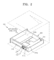
- FIG. 2 is a perspective view showing a state in which the paper feeding device 300 is inserted into the main body 100 in the image forming apparatus according to an embodiment of the present invention.
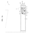
- FIG. 3A is a side view of the image forming apparatus according to an embodiment of the present invention.
- FIG. 3B is a detailed perspective view of the variable guide unit 150.
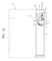
- FIG. 4A is a side view of the image forming apparatus to describe an operating state of the variable guide unit 150 when the number of recording media P remaining in the paper feeding device 300 is relatively large
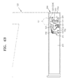
- FIG. 4B is a side view of the image forming apparatus illustrating an operating state of the variable guide unit 150 when the number of recording media P remaining in the paper feeding device 300 is relatively small.
- the variable guide unit 150 releases a pressure of the knock-up plate 330 towards the pickup roller 131 by lowering the knock-up plate 330 when the paper feeding device 300 is withdrawn from the main body 100. That is, the variable guide unit 150 moves the recording medium P stacked on the knock-up plate 330 away from the pickup roller 131 by lowering the knock-up plate 330 when the paper feeding device 300 is withdrawn from the main body 100. By doing this, a phenomenon in which the recording medium P stacked on the knock-up plate 330 remains in the main body 100 due to contact with the pickup roller 131 to cause a jam when the paper feeding device 300 is withdrawn from the main body 100 may be prevented.
- the variable guide unit 150 may be disposed on an insertion/withdrawal path of the paper feeding device 300 inside the main body 100, as shown in FIG. 2 .
- the variable guide unit 150 may be disposed on one side or on both sides of the insertion/withdrawal path so that the variable guide unit 150 accesses the knock-up plate 330 when the paper feeding device 300 is completely inserted into the main body 100.
- the variable guide unit 150 may include, for example, a variable guide member 151 that moves in response to a rising or a lowering, or both, of the knock-up plate 330 and a fixing member 155 for selectively allowing the movement of the variable guide member 151.
- variable guide member 151 may be, for example, rotatably assembled with the main body 100.
- the variable guide member 151 includes a slope unit 1511.
- the slope unit 1511 is fixed in a slope state based on a withdrawal direction of the paper feeding device 300 so as to lower the knock-up plate in a direction away from the pickup roller when the paper feeding device is being withdrawn from the main body.
- the knock-up plate 330 may include a contact unit 3301.
- the contact unit 3301 may be formed to protrude from the paper feeding cassette 310 through a hole 310a formed in a side of the paper feeding cassette 310 by, for example, extending from a side of the front end 330a of the knock-up plate 330.
- the slope unit 1511 contacts the contact unit 3301.
- the variable guide member 151 may rotate in a direction of the slope unit 1511 contacting the contact unit 3301 due to gravity.
- the variable guide member 151 may rotate in response to the rising or lowering of the knock-up plate 330 due to gravity, thereby maintaining a contact state of the slope unit 1511 with the contact unit 3301.
- the image forming apparatus may further include a first elastic member 152 for providing an elastic force to the variable guide member 151 in a direction in which the slope unit 1511 contacts the contact unit 3301.
- the first elastic member 152 may be a torsion spring, one end of which is supported by the main body 100 and the other end of which is supported by the variable guide member 151.
- the scope of the present invention is not limited thereto, and the first elastic member 152 may employ various elastic members, such as a compression coil spring, a tension coil spring, and a plate spring.
- the magnitude of the elastic force of the first elastic member 152 is less than the magnitude of the elastic force of the pressure member 331.
- the magnitude of the elastic force of the first elastic member 152 may be set sufficiently smaller than the magnitude of the elastic force of the pressure member 331 within a rotating limitation of the variable guide member 151 to contact the slope unit 1511 with the contact unit 3301.
- the variable guide member 151 is biased to rotate in the direction in which the slope unit 1511 contacts the contact unit 3301, by its own weight or the elastic force of the first elastic member 152.
- the knock-up plate 330 accordingly rises as shown in FIG. 4B , and the variable guide member 151 accordingly rotates in a counterclockwise direction while maintaining the contact state in which the slope unit 1511 contacts the contact unit 3301.
- the knock-up plate 330 accordingly lowers as shown in FIG.
- the variable guide member 151 accordingly rotates in a clockwise direction by gravity or the elastic force of the first elastic member 152 to maintain the state in which the slope unit 1511 contacts the contact unit 3301.
- the slope unit 1511 maintains the slope state based on the withdrawal direction in the states of FIGS. 4A and 4B . That is, the slope unit 1511 maintains the slope state based on the withdrawal direction even in a state in which a maximum number of recording media P are stacked on the knock-up plate 330 and a state in which no recording media P are stacked on the knock-up plate 330.
- the variable guide member 151 includes a release unit 1513.
- the release unit 1513 may be formed, for example, by grooving a lower side end of the slope unit 1511.
- the fixing member 155 allows the variable guide member 151 to move according to the rising or lowering of the knock-up plate 330 by being at a release position (refer to FIGS. 3A and 3B ) at which the fixing member 155 is released from the variable guide member 151 in a state where the paper feeding device 300 is inserted into the main body 100, and fixes the variable guide member 151 so as not to move by being at a fixing position (refer to FIG. 5B ) at which the fixing member 155 is coupled with the variable guide member 151 when the paper feeding device 300 is withdrawn from the main body.
- the fixing member 155 is rotatably assembled with the main body 100 to move to the fixing position or the release position.
- a second elastic member 156 provides an elastic force to the fixing member 155 in a direction in which the fixing member 155 moves to the fixing position.
- the second elastic member 156 may be a torsion spring, one end of which is supported by the main body 100 and the other end of which is supported by the fixing member 155.
- the scope of the present invention is not limited thereto, and the second elastic member 156 may employ various elastic members, such as a compression coil spring, a tension coil spring, and a plate spring.
- the paper feeding cassette 310 may include a switching member 311.
- the switching member 311 may be formed to protrude from a side of the paper feeding cassette 310.
- the fixing member 155 is located at the fixing position by the elastic force of the second elastic member 156.
- the switching member 311 contacts the fixing member 155 to push the fixing member 155 in a direction against the elastic force of the second elastic member 156. By doing so, the fixing member 155 may switch to the release position.
- the switching member 311 maintains a contact state with the fixing member 155, thereby maintaining the fixing member 155 at the release position.
- the variable guide member 151 includes a first coupling unit 1512
- the fixing member 155 includes a second coupling unit 1551.
- the first and second coupling units 1512 and 1551 may have complementary shapes.
- the first and second coupling units 1512 and 1551 may be a protrusion and a groove that can engage with each other, respectively.
- the first and second coupling units 1512 and 1551 may have gear shapes gearing or engaging with each other.
- the first and second coupling units 1512 and 1551 are engaged with each other to maintain the variable guide member 151 in a fixed state so as not to rotate.
- a position of the variable guide member 151 in relation to the fixing member 155 varies according to the number of recording media P stacked on the knock-up plate 330.
- the first and second coupling units 1512 and 1551 may have shapes including a plurality of gear teeth.
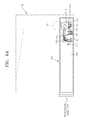
- FIGS. 6A and 6B are side views of the image forming apparatus to describe an operating state of the variable guide unit 150 in a withdrawal process of the paper feeding device 300.
- the slope unit 1511 of the variable guide member 151 maintains a contact state with the contact unit 3301 of the knock-up plate 330 by its own weight or the elastic force of the first elastic member 152. A process of withdrawing the paper feeding device 300 in this state is described.
- FIG. 6A illustrates the image forming apparatus immediately after pulling the paper feeding device 300 to withdraw the paper feeding device 300 from the main body 100.
- the fixing member 155 and the switching member 311 in a state where the paper feeding device 300 is inserted into the main body 100, are expressed as dotted lines for showing definitely an operating state of a variable guide unit 150.
- the switching member 311 formed on the paper feeding device 300 According to the movement of the paper feeding device 300 in a withdrawal direction to some degree in a state where the paper feeding device 300 is inserted into the main body 100, the switching member 311 formed on the paper feeding device 300 also moves in the withdrawal direction. According to the movement of the switching member 311 in the withdrawal direction, the contact between the fixing member 155 and the switching member 311 is released.
- the fixing member 155 rotates in a direction towards the variable guide member 151 by the elastic force of the second elastic member 156, thereby switching to the fixing position. Then, the first and second coupling units 1512 and 1551 are coupled with each other, and the variable guide member 151 is locked at a fixed position.
- FIG. 6B illustrates a state of the image forming apparatus in which the paper feeding device 300 moves further in the withdrawal direction in a locking state of the variable guide member 151.
- the switching member 311 and contact unit 3301 in a state of FIG. 6A are expressed as dotted lines for showing definitely an operating state of a variable guide unit 150.
- the knock-up plate 330 is a member disposed in the paper feeding device 300, the knock-up plate 330 moves according to the movement of the paper feeding device 300.
- the contact unit 3301 of the knock-up plate 330 contacts the slope unit 1511 of the variable guide member 151.
- the variable guide member 151 is locked by the fixing member 155.
- the contact unit 3301 is guided by the slope unit 1511 having a slope lowered in the withdrawal direction, thereby lowering the knock-up plate 330. Then, recording media P stacked on the knock-up plate 330 are separated from the pickup roller 131, thereby releasing the interference between the recording media P and the pickup roller 131.
- the contact unit 3301 lowers to some degree by being guided by the slope unit 1511 and enters into the release unit 1513 (refer to FIG. 3B ), thereby ending the contact between the contact unit 3301 and the slope unit 1511. Then, the paper feeding device 300 can be withdrawn from the main body 100.
- the variable guide member 151 is locked by the fixing member 155. Accordingly, when the paper feeding device 300 further moves in the withdrawal direction after the locking operation is completed, the knock-up plate 330 lowers due to the relationship between the slope unit 1511 and the contact unit 3301, thereby separating the stacked recording media P from the pickup roller 131.
- the knock-up plate 330 can lower at the same time as the withdrawal of the paper feeding device 300 regardless of the number of recording media P stacked on the knock-up plate 330, so that a problem in which the recording medium P remains inside the main body 100 due to the interference between the recording media P and the pickup roller 131 during withdrawal of the paper feeding device 300 can be solved.
- the knock-up plate 330 when the knock-up plate 330 lowers to a predetermined height, the knock-up plate 330 may be fixed to the paper feeding cassette 310 by a hooking member 333 included in the knock-up plate 330.
- the knock-up plate 330 lowers along the slope unit 1511 contacting with the contact unit 3301 and is fixed at the predetermined height in a process of withdrawing the paper feeding device 300, thereby preventing the knock-up plate 330 from rising even after the knock-up plate 330 passes through the release unit 1513.
- the knock-up plate 330 because the knock-up plate 330 is fixed to the paper feeding cassette 310 at the predetermined height, the paper feeding device 300 can be inserted again without the knock-up plate 330 being caught by the slope unit 1511.
- An image forming apparatus may prevent a jam due to a frictional force against a pickup roller by immediately removing a pressure relationship between the pickup roller and a recording medium during withdrawal of a paper feeding device regardless of the remaining number of recording media.
- the present invention has been particularly shown and described with reference to exemplary embodiments thereof, they are only illustrative.
- an image forming apparatus employing a printing unit for forming a color image by electrophotography using cyan-, magenta-, yellow-, and black-colored toners has been described in the exemplary embodiments, the present invention is not limited thereto.
- the image forming apparatus according to an embodiment of the present invention may be applied to image forming apparatuses for forming an image on a recording medium by using various methods, such as a printing unit for forming a single-colored image by electrophotography, a printing unit using ink-jet printing, and a printing unit using thermal transfer printing.
- various changes in form and details may be made therein without departing from the invention as defined by the following claims.
Landscapes
- Engineering & Computer Science (AREA)
- Mechanical Engineering (AREA)
- Physics & Mathematics (AREA)
- General Physics & Mathematics (AREA)
- Sheets, Magazines, And Separation Thereof (AREA)
Abstract
Description
- The present invention relates to an image forming apparatus, and more particularly, to an image forming apparatus with an improved paper feeding device for feeding a recording medium.
- Image forming apparatuses are generally used to form an image on a recording medium. Examples thereof include printers, copy machines, facsimile machines, and all-in-one devices implemented by combining functions of a printer, a copy machine, and a facsimile machine.
- Such image forming apparatuses generally include a paper feeding device for feeding a recording medium to a printing unit included in the image forming apparatus. The recording medium accommodated in the paper feeding device is picked up by a pickup roller and fed to the printing unit along a predetermined path. The pickup roller picks up the recording medium by using a frictional force against the recording medium. A frictional force sufficient for the pick-up requires a predetermined pressure relationship between the recording medium and the pickup roller. For the predetermined pressure relationship, a knock-up plate for pressing the recording medium against the pickup roller is used.
- However, because the knock-up plate presses the recording medium against the pickup roller even when the paper feeding device is withdrawn, a so-called jamming phenomenon occurs in which a portion of the recording medium is jammed because the recording medium remains due to the frictional force between the recording medium and the pickup roller, thereby resulting in faulty printing.
- To solve this problem, a method of releasing the pressure relationship between a recording medium and the pickup roller by lowering the knock-up plate when the paper feeding device is withdrawn has been proposed.
- Conventionally, by fixedly assembling a guide unit for guiding the knock-up plate to be lowered in a main body to lower the knock-up plate assembled with the paper feeding device along the fixed guide unit when the paper feeding device is withdrawn according to the method, a pressure relationship between the recording medium and the pickup roller can be released.
- However, because the guide unit has a fixed structure and provides a constant slope regardless of the remaining number of recording media accommodated in the paper feeding device, a gap between the guide unit and the knock-up plate varies according to the remaining number of recording media. In particular, when the remaining number of recording media is large, the gap between the guide unit and the knock-up plate is very large, and thus, the knock-up plate cannot be immediately lowered even when the paper feeding device is withdrawn and the pressure relationship is temporarily maintained, thereby resulting in a jam.
- One or more embodiments of the present invention relate to an image forming apparatus capable of preventing a jam in a withdrawal of a paper feeding device regardless of the remaining number of recording media.
- Additional aspects and/or advantages will be set forth in part in the description which follows and, in part, will be apparent from the description, or may be learned by practice of the embodiments described.
- According to an aspect of the present invention, there is provided an image forming apparatus including: a main body including a printing unit for printing an image on a recording medium and a pickup roller for picking up the recording medium; a paper feeding device, which includes an elevatable knock-up plate on which recording media are stackable and a pressure member for elastically pressing the knock-up plate towards the pickup roller and is removably inserted into the main body; and a variable guide unit, which is supported by the main body, is fixed in a slope state to lower the knock-up plate in a direction against the pickup roller when the paper feeding device is withdrawn from the main body, and moves to maintain a contact state with the knock-up plate due to a rising state of the knock-up plate in a state in which the paper feeding device is inserted into the main body.
- The variable guide unit may include: a variable guide member, which has a slope unit downwardly sloped in a withdrawal direction to lower the knock-up plate in a direction against the pickup roller by contacting with a contact unit of the knock-up plate when the paper feeding device is withdrawn from the main body and is supported by the main body for the slope unit to maintain a contact state with the contact unit due to a rising state of the knock-up plate; and a fixing member, which is supported by the main body, moves to a fixing position for fixing the variable guide member to be coupled with the variable guide member when the paper feeding device is withdrawn from the main body, and moves to a release position for releasing the variable guide member to be decoupled from the variable guide member when the paper feeding device is inserted into the main body.
- The slope unit may include a release unit for allowing the contact unit to be released from the slope unit after the knock-up plate is lowered.
- The contact unit may be formed to protrude from the knock-up plate, and the release unit may be formed as a groove in the slope unit so that the contact unit passes through the release unit.
- The image forming apparatus may further include a first elastic member for providing an elastic force to the variable guide member in a direction in which the slope unit contacts the contact unit.
- The elastic force of the first elastic member may be less than a pressure of the pressure member.
- The image forming apparatus may further include: a second elastic member for providing an elastic force in a direction in which the fixing member moves to the fixing position; and a switching member for switching to the release position in contact with the fixing member when the paper feeding device is inserted into the main body.
- The switching member may maintain the fixing member at the release position by maintaining a contact state with the fixing member in a state in which the insertion of the paper feeding device is completed.
- The variable guide unit may include a first coupling unit, and the fixing member may include a second coupling unit having a shape complementary to the first coupling unit, the second coupling unit being coupled with the first coupling unit when the fixing member is located at the fixing position.
- The first and second coupling units may have gear shapes gearing with each other.
- According to another aspect of the present invention, there is provided a variable guide unit rotatably installed in a main body of a printing apparatus including: a paper feeding device with a pickup roller and a knock-up plate, the variable guide unit including: a variable guide member including a slope unit downwardly sloped in a withdrawal direction to lower the knock-up plate in a direction away from the pickup roller by contacting a contact unit of the knock-up plate when the paper feeding device is withdrawn from the main body and is supported by the main body for the slope unit to maintain a contact state with the contact unit due to a rising state of the knock-up plate; and a fixing member, which is supported by the main body, to move to a fixing position for fixing the variable guide member by coupling with the variable guide member when the paper feeding device is withdrawn from the main body and to move to a release position for releasing the variable guide member by decoupling from the variable guide member when the paper feeding device is inserted into the main body.
- The above and other features and advantages of the present invention will become more apparent by describing in detail exemplary embodiments thereof with reference to the attached drawings in which:
-
FIG. 1 is a schematic configuration of an image forming apparatus according to an embodiment of the present invention; -
FIG. 2 is a perspective view showing a state in which a paper feeding device is inserted into a main body in the image forming apparatus according to an embodiment of the present invention; -
FIG. 3A is a side view of the image forming apparatus according to an embodiment of the present invention; -
FIG. 3B is a detailed perspective view of a variable guide unit; -
FIG. 4A is a side view of the image forming apparatus to describe an operating state of the variable guide unit when the remaining number of recording media in the paper feeding device is relatively large; -
FIG. 4B is a side view of the image forming apparatus to describe an operating state of the variable guide unit when the remaining number of recording media in the paper feeding device is relatively small; -
FIGS. 5A and 5B are rear views of the variable guide unit showing a state in which a fixing member is coupled with a variable guide member and released from a variable guide member; -
FIGS. 6A and6B are side views of the image forming apparatus to describe an operating state of the variable guide unit in a process of withdrawing the paper feeding device in a state of the image forming apparatus shown inFIG. 4A . - One or more embodiments of the present invention will now be described more fully with reference to the accompanying drawings, in which exemplary embodiments are shown.
-
FIG. 1 is a schematic configuration of an image forming apparatus according to an embodiment of the present invention. - As shown in
FIG. 1 , the image forming apparatus may include, for example, amain body 100 and apaper feeding device 300. - The
main body 100 may include, for example, aprinting unit 110, apickup unit 130, and a variable guide unit such asvariable guide unit 150 ofFIG. 2 . - The
printing unit 110 may form an image on a recording medium P. In detail, theprinting unit 110 forms an image on the recording medium P by electrophotography. Theprinting unit 111 may includedevelopers 111, anintermediate transfer belt 115, anintermediate transfer roller 116, afinal transfer roller 118, a light-exposure unit 119, and afuser 120. Theprinting unit 110 forms a color image by using cyan-, magenta-, yellow-, and black-colored toners. To do this, fourdevelopers 111 for accommodating the cyan-, magenta-, yellow-, and black-colored toners, respectively, are used. - The light-
exposure unit 119 forms a static latent image by radiating light modulated in correspondence with image information onto aphotosensitive drum 112 of each of thedevelopers 111. The light-exposure unit 119 may employ a Light Emitting Diode (LED) light-exposure unit in which a plurality of LEDs arranged in a main scanning direction selectively emit light. Alternatively, the light-exposure unit 119 may employ a Laser Scanning Unit (LSU) for deflecting light radiated from a laser diode in the main scanning direction by using a light deflector and radiating the deflected light onto thephotosensitive drum 112. - The
photosensitive drum 112 is an example of a photosensitive body on which a static latent image is formed. Thephotosensitive drum 112 may be formed by forming a photosensitive layer having light conductivity around a cylindrical metal pipe. - The
developer 111 forms a toner image by attaching a toner accommodated therein to the static latent image formed on thephotosensitive drum 112. Thedeveloper 111 may include a developingroller 113 for supplying the toner accommodated in thedeveloper 111 to the static latent image formed on thephotosensitive drum 112 and anelectrifying roller 114 for electrifying the surface of thephotosensitive drum 112 with a uniform potential. - A developing bias voltage for supplying a toner to a static latent image is applied to the developing
roller 113, and an electrifying bias voltage is applied to theelectrifying roller 114. Here, a corona electrifying unit (not shown) may be employed instead of theelectrifying roller 114. - The
intermediate transfer belt 115 is an intermediate transfer medium to which the toner image is temporarily transferred before the toner image is finally transferred to the recording medium P, and that is supported by supportingrollers 117 to be able to circulate. - The
intermediate transfer roller 116 is an example of an intermediate transfer member for transferring the toner image formed on thephotosensitive drum 112 to theintermediate transfer belt 115. Fourintermediate transfer rollers 116 face fourphotosensitive drums 112, respectively, with theintermediate transfer belt 115 therebetween. An intermediate transfer bias voltage for transferring the toner image formed on thephotosensitive drum 112 to theintermediate transfer belt 115 is applied to theintermediate transfer roller 116. The cyan-, magenta-, yellow-, and black-colored toner images formed on the fourphotosensitive drums 112 in the fourdevelopers 111, respectively, are transferred to theintermediate transfer belt 115 by an intermediate transfer electric field formed by the intermediate transfer bias voltage. - The
final transfer roller 118 is an example of a final transfer unit for transferring the toner image on theintermediate transfer belt 115 to the recording medium P. A final transfer bias voltage for transferring the toner image on theintermediate transfer belt 115 to the recording medium P is applied to thefinal transfer roller 118. A corona transfer unit (not shown) may be employed instead of thefinal transfer roller 118. While the recording medium P is travelling between theintermediate transfer belt 115 and thefinal transfer roller 118, the toner image on theintermediate transfer belt 115 is transferred to the recording medium P by a final transfer electric field formed by the final transfer bias voltage. - The
fuser 120 fixes the toner image to the recording medium P by providing heat and pressure to the toner image transferred to the recording medium P. The recording medium P, which has undergone the fixing process, is discharged from themain body 100. - The
pickup unit 130 picks up the recording medium P accommodated in thepaper feeding device 300 and feeds the recording medium P to theprinting unit 110. Thepickup unit 130 may include apickup roller 131 for directly contacting with and picking up the recording medium P accommodated in thepaper feeding device 300 and a feed roller 133 for feeding the recording medium P picked up by thepickup roller 131 to theprinting unit 110. - The
paper feeding device 300 accommodates the recording medium P on which an image is formed and is removably inserted into themain body 100. - The
paper feeding device 300 includes apaper feeding cassette 310 for accommodating the recording medium P. Thepaper feeding cassette 310 includes an elevation plate or elevatable knock-upplate 330. The recording media P are stacked on the knock-upplate 330. The knock-upplate 330 rises against thepickup roller 131 to contact the stacked recording medium P with thepickup roller 131. - Referring now to
FIG. 2 , thevariable guide unit 150 may act as a guide to release a pressure relationship between thepickup roller 131 and the recording medium P when thepaper feeding device 300 is withdrawn from themain body 100, as described below. - In an embodiment, the knock-up
plate 330 may be rotatably assembled with thepaper feeding cassette 310. The knock-upplate 330 may be assembled with thepaper feeding cassette 310 by a hinge axis included in arear end 330b of the knock-upplate 330, thereby making afront end 330a of the knock-upplate 330 rise upwards or lower downwards according to the number of stacked recording media P. That is, thefront end 330a of the knock-upplate 330 rise upwards towards thepickup roller 131 or lowers downwards away from thepickup roller 131 according to the number of stacked recording media P. The knock-upplate 330 may be elastically pressed in a direction of thepickup roller 131, that is, towards thepickup roller 131, by apressure member 331. Thepressure member 331 may be, for example, a compression coil spring interposed between the knock-upplate 330 and thepaper feeding cassette 310, however, the scope of the present invention is not limited thereto. Thepressure member 331 may employ various members capable of pressing the knock-upplate 330 towards thepickup roller 131. When the remaining number of recording media P accommodated in thepaper feeding cassette 310 is small, the knock-upplate 330 rises to be nearer to thepickup roller 131 due to the elastic force of thepressure member 331, and when the remaining number of recording media P accommodated in thepaper feeding cassette 310 is large, the knock-upplate 330 lowers in a direction opposing the elastic force of thepressure member 331, thereby distancing the knock-upplate 330 from thepickup roller 131. Accordingly, the uppermost or topmost one of the recording media P stacked on the knock-upplate 330 always maintains a contact state with thepickup roller 131. -
FIG. 2 is a perspective view showing a state in which thepaper feeding device 300 is inserted into themain body 100 in the image forming apparatus according to an embodiment of the present invention.FIG. 3A is a side view of the image forming apparatus according to an embodiment of the present invention.FIG. 3B is a detailed perspective view of thevariable guide unit 150.FIG. 4A is a side view of the image forming apparatus to describe an operating state of thevariable guide unit 150 when the number of recording media P remaining in thepaper feeding device 300 is relatively large, andFIG. 4B is a side view of the image forming apparatus illustrating an operating state of thevariable guide unit 150 when the number of recording media P remaining in thepaper feeding device 300 is relatively small. - The
variable guide unit 150 releases a pressure of the knock-upplate 330 towards thepickup roller 131 by lowering the knock-upplate 330 when thepaper feeding device 300 is withdrawn from themain body 100. That is, thevariable guide unit 150 moves the recording medium P stacked on the knock-upplate 330 away from thepickup roller 131 by lowering the knock-upplate 330 when thepaper feeding device 300 is withdrawn from themain body 100. By doing this, a phenomenon in which the recording medium P stacked on the knock-upplate 330 remains in themain body 100 due to contact with thepickup roller 131 to cause a jam when thepaper feeding device 300 is withdrawn from themain body 100 may be prevented. - The
variable guide unit 150 may be disposed on an insertion/withdrawal path of thepaper feeding device 300 inside themain body 100, as shown inFIG. 2 . For example, thevariable guide unit 150 may be disposed on one side or on both sides of the insertion/withdrawal path so that thevariable guide unit 150 accesses the knock-upplate 330 when thepaper feeding device 300 is completely inserted into themain body 100. - The
variable guide unit 150 may include, for example, avariable guide member 151 that moves in response to a rising or a lowering, or both, of the knock-upplate 330 and a fixingmember 155 for selectively allowing the movement of thevariable guide member 151. - Referring to
FIGS. 3A and3B , thevariable guide member 151 may be, for example, rotatably assembled with themain body 100. Thevariable guide member 151 includes aslope unit 1511. Theslope unit 1511 is fixed in a slope state based on a withdrawal direction of thepaper feeding device 300 so as to lower the knock-up plate in a direction away from the pickup roller when the paper feeding device is being withdrawn from the main body. - The knock-up
plate 330 may include acontact unit 3301. Thecontact unit 3301 may be formed to protrude from thepaper feeding cassette 310 through ahole 310a formed in a side of thepaper feeding cassette 310 by, for example, extending from a side of thefront end 330a of the knock-upplate 330. - The
slope unit 1511 contacts thecontact unit 3301. Thevariable guide member 151 may rotate in a direction of theslope unit 1511 contacting thecontact unit 3301 due to gravity. When the knock-upplate 330 rises or lowers according to the effect of gravity on the number of recording media P stacked on the knock-upplate 330, thevariable guide member 151 may rotate in response to the rising or lowering of the knock-upplate 330 due to gravity, thereby maintaining a contact state of theslope unit 1511 with thecontact unit 3301. The image forming apparatus may further include a firstelastic member 152 for providing an elastic force to thevariable guide member 151 in a direction in which theslope unit 1511 contacts thecontact unit 3301. For example, the firstelastic member 152 may be a torsion spring, one end of which is supported by themain body 100 and the other end of which is supported by thevariable guide member 151. However, the scope of the present invention is not limited thereto, and the firstelastic member 152 may employ various elastic members, such as a compression coil spring, a tension coil spring, and a plate spring. The magnitude of the elastic force of the firstelastic member 152 is less than the magnitude of the elastic force of thepressure member 331. Not to obstruct rising of the knock-upplate 330, the magnitude of the elastic force of the firstelastic member 152 may be set sufficiently smaller than the magnitude of the elastic force of thepressure member 331 within a rotating limitation of thevariable guide member 151 to contact theslope unit 1511 with thecontact unit 3301. - The
variable guide member 151 is biased to rotate in the direction in which theslope unit 1511 contacts thecontact unit 3301, by its own weight or the elastic force of the firstelastic member 152. When the number of recording media P stacked on the knock-upplate 330 is gradually reduced by performing a printing operation in this biased state, the knock-upplate 330 accordingly rises as shown inFIG. 4B , and thevariable guide member 151 accordingly rotates in a counterclockwise direction while maintaining the contact state in which theslope unit 1511 contacts thecontact unit 3301. In addition, if additional recording media P are stacked on the knock-upplate 330, the knock-upplate 330 accordingly lowers as shown inFIG. 4A , and thevariable guide member 151 accordingly rotates in a clockwise direction by gravity or the elastic force of the firstelastic member 152 to maintain the state in which theslope unit 1511 contacts thecontact unit 3301. In addition, theslope unit 1511 maintains the slope state based on the withdrawal direction in the states ofFIGS. 4A and4B . That is, theslope unit 1511 maintains the slope state based on the withdrawal direction even in a state in which a maximum number of recording media P are stacked on the knock-upplate 330 and a state in which no recording media P are stacked on the knock-upplate 330. - Referring to
FIG. 3B again, when the knock-upplate 330 lowers to some degree with an interference between theslope unit 1511 and thecontact unit 3301 in a withdrawal process of thepaper feeding device 300, thepaper feeding device 300 is completely withdrawn from themain body 100 only if the interference between theslope unit 1511 and thecontact unit 3301 is released. To do this, thevariable guide member 151 includes arelease unit 1513. Therelease unit 1513 may be formed, for example, by grooving a lower side end of theslope unit 1511. When thecontact unit 3301 lowers to some degree by being guided by theslope unit 1511, thecontact unit 3301 enters into therelease unit 1513, thereby ending the contact between thecontact unit 3301 and theslope unit 1511. Then, thepaper feeding device 300 can be withdrawn from themain body 100. - Referring to
FIGS. 3A and3B again, the fixingmember 155 allows thevariable guide member 151 to move according to the rising or lowering of the knock-upplate 330 by being at a release position (refer toFIGS. 3A and3B ) at which the fixingmember 155 is released from thevariable guide member 151 in a state where thepaper feeding device 300 is inserted into themain body 100, and fixes thevariable guide member 151 so as not to move by being at a fixing position (refer toFIG. 5B ) at which the fixingmember 155 is coupled with thevariable guide member 151 when thepaper feeding device 300 is withdrawn from the main body. - For example, the fixing
member 155 is rotatably assembled with themain body 100 to move to the fixing position or the release position. A secondelastic member 156 provides an elastic force to the fixingmember 155 in a direction in which the fixingmember 155 moves to the fixing position. For example, the secondelastic member 156 may be a torsion spring, one end of which is supported by themain body 100 and the other end of which is supported by the fixingmember 155. However, the scope of the present invention is not limited thereto, and the secondelastic member 156 may employ various elastic members, such as a compression coil spring, a tension coil spring, and a plate spring. - Switching of the fixing
member 155 to the release position may be performed in connection with an insertion process of thepaper feeding device 300. Thepaper feeding cassette 310 may include a switchingmember 311. For example, as shown inFIG. 3B , the switchingmember 311 may be formed to protrude from a side of thepaper feeding cassette 310. In a state where thepaper feeding device 300 is withdrawn from themain body 100, the fixingmember 155 is located at the fixing position by the elastic force of the secondelastic member 156. When thepaper feeding device 300 is inserted into themain body 100, the switchingmember 311 contacts the fixingmember 155 to push the fixingmember 155 in a direction against the elastic force of the secondelastic member 156. By doing so, the fixingmember 155 may switch to the release position. In a state where thepaper feeding device 300 is inserted into themain body 100, the switchingmember 311 maintains a contact state with the fixingmember 155, thereby maintaining the fixingmember 155 at the release position. - At the fixing position, the fixing
member 155 is coupled with thevariable guide member 151 to lock thevariable guide member 151 so that thevariable guide member 151 does not rotate. Referring toFIGS. 3B ,5A, and 5B , thevariable guide member 151 includes afirst coupling unit 1512, and the fixingmember 155 includes asecond coupling unit 1551. The first andsecond coupling units second coupling units FIG. 5A , the first andsecond coupling units FIG. 5B , when the fixingmember 155 is located at the fixing position, the first andsecond coupling units variable guide member 151 in a fixed state so as not to rotate. A position of thevariable guide member 151 in relation to the fixingmember 155 varies according to the number of recording media P stacked on the knock-upplate 330. In order for the fixingmember 155 to easily lock thevariable guide member 151 even in this case, the first andsecond coupling units -
FIGS. 6A and6B are side views of the image forming apparatus to describe an operating state of thevariable guide unit 150 in a withdrawal process of thepaper feeding device 300. - Even though the number of recording media P stacked on the knock-up
plate 330 varies, theslope unit 1511 of thevariable guide member 151 maintains a contact state with thecontact unit 3301 of the knock-upplate 330 by its own weight or the elastic force of the firstelastic member 152. A process of withdrawing thepaper feeding device 300 in this state is described. -
FIG. 6A illustrates the image forming apparatus immediately after pulling thepaper feeding device 300 to withdraw thepaper feeding device 300 from themain body 100. InFIG. 6A , the fixingmember 155 and the switchingmember 311, in a state where thepaper feeding device 300 is inserted into themain body 100, are expressed as dotted lines for showing definitely an operating state of avariable guide unit 150. According to the movement of thepaper feeding device 300 in a withdrawal direction to some degree in a state where thepaper feeding device 300 is inserted into themain body 100, the switchingmember 311 formed on thepaper feeding device 300 also moves in the withdrawal direction. According to the movement of the switchingmember 311 in the withdrawal direction, the contact between the fixingmember 155 and the switchingmember 311 is released. Accordingly, the fixingmember 155 rotates in a direction towards thevariable guide member 151 by the elastic force of the secondelastic member 156, thereby switching to the fixing position. Then, the first andsecond coupling units variable guide member 151 is locked at a fixed position. -
FIG. 6B illustrates a state of the image forming apparatus in which thepaper feeding device 300 moves further in the withdrawal direction in a locking state of thevariable guide member 151. InFIG. 6B , the switchingmember 311 andcontact unit 3301 in a state ofFIG. 6A are expressed as dotted lines for showing definitely an operating state of avariable guide unit 150. Referring toFIG. 6B , because the knock-upplate 330 is a member disposed in thepaper feeding device 300, the knock-upplate 330 moves according to the movement of thepaper feeding device 300. Thecontact unit 3301 of the knock-upplate 330 contacts theslope unit 1511 of thevariable guide member 151. In addition, thevariable guide member 151 is locked by the fixingmember 155. According to the movement of thepaper feeding device 300 in the withdrawal direction, thecontact unit 3301 is guided by theslope unit 1511 having a slope lowered in the withdrawal direction, thereby lowering the knock-upplate 330. Then, recording media P stacked on the knock-upplate 330 are separated from thepickup roller 131, thereby releasing the interference between the recording media P and thepickup roller 131. - If the
paper feeding device 300 further moves in the withdrawal direction in the interference release state, even though not shown, thecontact unit 3301 lowers to some degree by being guided by theslope unit 1511 and enters into the release unit 1513 (refer toFIG. 3B ), thereby ending the contact between thecontact unit 3301 and theslope unit 1511. Then, thepaper feeding device 300 can be withdrawn from themain body 100. - As described above, according to an embodiment of the present invention, as soon as the
paper feeding device 300 starts to be withdrawn in a state where theslope unit 1511 of thevariable guide member 151 contacts thecontact unit 3301 of the knock-upplate 330, thevariable guide member 151 is locked by the fixingmember 155. Accordingly, when thepaper feeding device 300 further moves in the withdrawal direction after the locking operation is completed, the knock-upplate 330 lowers due to the relationship between theslope unit 1511 and thecontact unit 3301, thereby separating the stacked recording media P from thepickup roller 131. Accordingly, when thepaper feeding device 300 is withdrawn, the knock-upplate 330 can lower at the same time as the withdrawal of thepaper feeding device 300 regardless of the number of recording media P stacked on the knock-upplate 330, so that a problem in which the recording medium P remains inside themain body 100 due to the interference between the recording media P and thepickup roller 131 during withdrawal of thepaper feeding device 300 can be solved. - Although not shown, when the knock-up
plate 330 lowers to a predetermined height, the knock-upplate 330 may be fixed to thepaper feeding cassette 310 by a hookingmember 333 included in the knock-upplate 330. The knock-upplate 330 lowers along theslope unit 1511 contacting with thecontact unit 3301 and is fixed at the predetermined height in a process of withdrawing thepaper feeding device 300, thereby preventing the knock-upplate 330 from rising even after the knock-upplate 330 passes through therelease unit 1513. In addition, because the knock-upplate 330 is fixed to thepaper feeding cassette 310 at the predetermined height, thepaper feeding device 300 can be inserted again without the knock-upplate 330 being caught by theslope unit 1511. - An image forming apparatus according to an embodiment of the present invention may prevent a jam due to a frictional force against a pickup roller by immediately removing a pressure relationship between the pickup roller and a recording medium during withdrawal of a paper feeding device regardless of the remaining number of recording media.
- While the present invention has been particularly shown and described with reference to exemplary embodiments thereof, they are only illustrative. For example, although an image forming apparatus employing a printing unit for forming a color image by electrophotography using cyan-, magenta-, yellow-, and black-colored toners has been described in the exemplary embodiments, the present invention is not limited thereto. The image forming apparatus according to an embodiment of the present invention may be applied to image forming apparatuses for forming an image on a recording medium by using various methods, such as a printing unit for forming a single-colored image by electrophotography, a printing unit using ink-jet printing, and a printing unit using thermal transfer printing. Further, it will be understood by those of ordinary skill in the art that various changes in form and details may be made therein without departing from the invention as defined by the following claims.
Claims (11)
- An image forming apparatus comprising:a main body comprising a printing unit for printing an image on a recording medium and a pickup roller for picking up the recording medium;a paper feeding device, which comprises an elevatable plate on which recording media are stackable and a pressure member for elastically pressing the plate towards the pickup roller, and is removably inserted into the main body; anda variable guide unit, which is supported by the main body, is fixed in a slope state so as to lower the plate in a direction away from the pickup roller when the paper feeding device is being withdrawn from the main body, and moves to maintain a contact state with the plate when the paper feeding device is inserted into the main body.
- The image forming apparatus of claim 1, wherein the variable guide unit comprises:a variable guide member, which has a slope unit downwardly sloped in a withdrawal direction to lower the plate in a direction away from the pickup roller by contacting a contact unit of the plate when the paper feeding device is withdrawn from the main body and is supported by the main body for the slope unit to maintain a contact state with the contact unit due to a rising state of the plate; anda fixing member, which is supported by the main body, moves to a fixing position for fixing the variable guide member by coupling with the variable guide member when the paper feeding device is withdrawn from the main body and moves to a release position for releasing the variable guide member by decoupling from the variable guide member when the paper feeding device is inserted into the main body.
- The image forming apparatus of claim 2, wherein the slope unit comprises a release unit for allowing the contact unit to be released from the slope unit after the plate is lowered.
- The image forming apparatus of claim 3, wherein the contact unit is formed to protrude from the plate, and the release unit is formed as a groove in the slope unit so that the contact unit passes through the release unit.
- The image forming apparatus of claim 2, further comprising a first elastic member for providing an elastic force to the variable guide member in a direction in which the slope unit contacts the contact unit.
- The image forming apparatus of claim 5, wherein the elastic force of the first elastic member is less than a pressure exerted by the pressure member.
- The image forming apparatus of claim 2, further comprising:a second elastic member for providing an elastic force in a direction in which the fixing member moves to the fixing position; anda switching member for switching to the release position in contact with the fixing member when the paper feeding device is inserted into the main body.
- The image forming apparatus of claim 7, wherein the switching member maintains the fixing member at the release position by maintaining a contact state with the fixing member in a state in which the insertion of the paper feeding device is completed.
- The image forming apparatus of claim 2, wherein the variable guide unit comprises a first coupling unit, and the fixing member comprises a second coupling unit having a shape complementary to the first coupling unit, the second coupling unit being coupled with the first coupling unit when the fixing member is located at the fixing position.
- The image forming apparatus of claim 9, wherein the first and second coupling units have gear shapes that gear with each other.
- A variable guide unit rotatably installed in a main body of a printing apparatus including a paper feeding device with a pickup roller and an elevatable plate, the variable guide unit comprising:a variable guide member comprising a slope unit downwardly sloped in a withdrawal direction to lower the plate in a direction away from the pickup roller by contacting a contact unit of the plate when the paper feeding device is withdrawn from the main body and is supported by the main body for the slope unit to maintain a contact state with the contact unit due to a rising state of the plate; anda fixing member, which is supported by the main body, to move to a fixing position for fixing the variable guide member by coupling with the variable guide member when the paper feeding device is withdrawn from the main body and to move to a release position for releasing the variable guide member by decoupling from the variable guide member when the paper feeding device is inserted into the main body.
Applications Claiming Priority (1)
| Application Number | Priority Date | Filing Date | Title |
|---|---|---|---|
| KR1020110134463A KR101813642B1 (en) | 2011-12-14 | 2011-12-14 | image forming apparatus |
Publications (3)
| Publication Number | Publication Date |
|---|---|
| EP2612830A2 true EP2612830A2 (en) | 2013-07-10 |
| EP2612830A3 EP2612830A3 (en) | 2013-10-02 |
| EP2612830B1 EP2612830B1 (en) | 2019-08-21 |
Family
ID=46727150
Family Applications (1)
| Application Number | Title | Priority Date | Filing Date |
|---|---|---|---|
| EP12182392.6A Not-in-force EP2612830B1 (en) | 2011-12-14 | 2012-08-30 | Image forming apparatus |
Country Status (3)
| Country | Link |
|---|---|
| US (1) | US8910933B2 (en) |
| EP (1) | EP2612830B1 (en) |
| KR (1) | KR101813642B1 (en) |
Cited By (1)
| Publication number | Priority date | Publication date | Assignee | Title |
|---|---|---|---|---|
| EP3643649A1 (en) * | 2018-10-26 | 2020-04-29 | Toshiba Tec Kabushiki Kaisha | Image processing apparatus comprising a sheet feed cassette |
Families Citing this family (7)
| Publication number | Priority date | Publication date | Assignee | Title |
|---|---|---|---|---|
| JP6428303B2 (en) * | 2015-01-24 | 2018-11-28 | 株式会社リコー | Paper feeding device, image forming device |
| JP6274137B2 (en) * | 2015-03-13 | 2018-02-07 | 京セラドキュメントソリューションズ株式会社 | Conveying device and image forming apparatus having the same |
| JP2018095412A (en) * | 2016-12-14 | 2018-06-21 | コニカミノルタ株式会社 | Image forming apparatus |
| JP6819434B2 (en) * | 2017-04-18 | 2021-01-27 | 株式会社リコー | Image forming device and storage device |
| KR20200011809A (en) * | 2018-07-25 | 2020-02-04 | 휴렛-팩커드 디벨롭먼트 컴퍼니, 엘.피. | Pickup roller rotated by driving force for moving knock-up plate |
| JP7159724B2 (en) * | 2018-09-12 | 2022-10-25 | 富士フイルムビジネスイノベーション株式会社 | Media feeding device and image forming device |
| CN111127740B (en) * | 2020-01-02 | 2022-05-31 | 山东新北洋信息技术股份有限公司 | Sheet-like medium dispensing device and cash recycling apparatus |
Family Cites Families (10)
| Publication number | Priority date | Publication date | Assignee | Title |
|---|---|---|---|---|
| JPS55151445A (en) * | 1979-05-07 | 1980-11-26 | Ricoh Co Ltd | Fitting and removing device for leverless cassette in copying machine |
| US4540169A (en) * | 1983-10-03 | 1985-09-10 | Xerox Corporation | Cassette sheet feed apparatus |
| EP0204227B1 (en) * | 1985-05-24 | 1990-09-12 | Mita Industrial Co. Ltd. | Paper feeding device |
| JPS63218437A (en) * | 1987-03-03 | 1988-09-12 | Seikosha Co Ltd | Sheet feeding device for printer |
| JP2634972B2 (en) * | 1991-07-24 | 1997-07-30 | 三田工業株式会社 | Paper feeder |
| DE69321771T2 (en) * | 1992-06-24 | 1999-05-06 | Canon K.K., Tokio/Tokyo | Apparatus for feeding sheets |
| US6106178A (en) * | 1999-04-12 | 2000-08-22 | Hewlett-Packard Company | Printer and printer paper tray |
| US7448613B2 (en) * | 2006-02-28 | 2008-11-11 | Canon Kabushiki Kaisha | Sheet feeding apparatus and image forming apparatus |
| JP5511348B2 (en) | 2009-12-10 | 2014-06-04 | キヤノン株式会社 | Sheet feeding apparatus and image forming apparatus provided with the sheet feeding apparatus |
| KR101758626B1 (en) | 2010-11-18 | 2017-07-17 | 에스프린팅솔루션 주식회사 | Image forming apparatus |
-
2011
- 2011-12-14 KR KR1020110134463A patent/KR101813642B1/en not_active Expired - Fee Related
-
2012
- 2012-08-30 EP EP12182392.6A patent/EP2612830B1/en not_active Not-in-force
- 2012-10-31 US US13/665,050 patent/US8910933B2/en not_active Expired - Fee Related
Non-Patent Citations (1)
| Title |
|---|
| None |
Cited By (1)
| Publication number | Priority date | Publication date | Assignee | Title |
|---|---|---|---|---|
| EP3643649A1 (en) * | 2018-10-26 | 2020-04-29 | Toshiba Tec Kabushiki Kaisha | Image processing apparatus comprising a sheet feed cassette |
Also Published As
| Publication number | Publication date |
|---|---|
| US8910933B2 (en) | 2014-12-16 |
| EP2612830A3 (en) | 2013-10-02 |
| EP2612830B1 (en) | 2019-08-21 |
| KR20130067667A (en) | 2013-06-25 |
| US20130154184A1 (en) | 2013-06-20 |
| KR101813642B1 (en) | 2017-12-29 |
Similar Documents
| Publication | Publication Date | Title |
|---|---|---|
| EP2612830B1 (en) | Image forming apparatus | |
| EP2612831B1 (en) | Paper feeding apparatus and image forming apparatus adopting the same | |
| KR101402546B1 (en) | Electrophotographic image forming apparatus | |
| EP2725428B1 (en) | Image forming apparatus, and method of transmitting power and method of mounting developing unit in the same | |
| KR101521076B1 (en) | Image forming apparatus and paper feeding device thereof | |
| US20140140745A1 (en) | Power transmitting apparatus and image forming apparatus adopting the same | |
| US9126788B2 (en) | Image forming apparatus | |
| US20120061907A1 (en) | Sheet supplying device and image forming apparatus incorporating same | |
| US9731918B2 (en) | Roller separation device and image forming apparatus using the same | |
| US8185037B2 (en) | Sheet feeding device and image forming apparatus including the same | |
| US9067735B2 (en) | Paper feeding apparatus and image forming apparatus including the same | |
| US9533846B2 (en) | Drawer unit, and image forming apparatus using the drawer unit | |
| US7600749B2 (en) | Paper feeding device and image forming apparatus including the same | |
| KR101638880B1 (en) | Image forming apparatus | |
| JP5504947B2 (en) | Paper feeding device and image forming apparatus having the same | |
| JP5007847B2 (en) | Paper feeding mechanism and image forming apparatus | |
| JP6143801B2 (en) | Image forming apparatus | |
| JP6558143B2 (en) | Image forming apparatus | |
| JP6277742B2 (en) | Paper feeding device and image forming apparatus | |
| JP5421168B2 (en) | Paper feeding device and image forming apparatus having the same | |
| JPH0710298A (en) | Paper feeder | |
| JP2017210315A (en) | Sheet feeding cassette and image formation apparatus |
Legal Events
| Date | Code | Title | Description |
|---|---|---|---|
| PUAI | Public reference made under article 153(3) epc to a published international application that has entered the european phase |
Free format text: ORIGINAL CODE: 0009012 |
|
| AK | Designated contracting states |
Kind code of ref document: A2 Designated state(s): AL AT BE BG CH CY CZ DE DK EE ES FI FR GB GR HR HU IE IS IT LI LT LU LV MC MK MT NL NO PL PT RO RS SE SI SK SM TR |
|
| AX | Request for extension of the european patent |
Extension state: BA ME |
|
| PUAL | Search report despatched |
Free format text: ORIGINAL CODE: 0009013 |
|
| AK | Designated contracting states |
Kind code of ref document: A3 Designated state(s): AL AT BE BG CH CY CZ DE DK EE ES FI FR GB GR HR HU IE IS IT LI LT LU LV MC MK MT NL NO PL PT RO RS SE SI SK SM TR |
|
| AX | Request for extension of the european patent |
Extension state: BA ME |
|
| RIC1 | Information provided on ipc code assigned before grant |
Ipc: B41J 13/10 20060101ALI20130823BHEP Ipc: B65H 1/12 20060101AFI20130823BHEP Ipc: G03G 15/00 20060101ALI20130823BHEP |
|
| 17P | Request for examination filed |
Effective date: 20140321 |
|
| RBV | Designated contracting states (corrected) |
Designated state(s): AL AT BE BG CH CY CZ DE DK EE ES FI FR GB GR HR HU IE IS IT LI LT LU LV MC MK MT NL NO PL PT RO RS SE SI SK SM TR |
|
| RAP1 | Party data changed (applicant data changed or rights of an application transferred) |
Owner name: S-PRINTING SOLUTION CO., LTD. |
|
| RAP1 | Party data changed (applicant data changed or rights of an application transferred) |
Owner name: HP PRINTING KOREA CO., LTD. |
|
| STAA | Information on the status of an ep patent application or granted ep patent |
Free format text: STATUS: EXAMINATION IS IN PROGRESS |
|
| 17Q | First examination report despatched |
Effective date: 20181114 |
|
| GRAP | Despatch of communication of intention to grant a patent |
Free format text: ORIGINAL CODE: EPIDOSNIGR1 |
|
| STAA | Information on the status of an ep patent application or granted ep patent |
Free format text: STATUS: GRANT OF PATENT IS INTENDED |
|
| INTG | Intention to grant announced |
Effective date: 20190527 |
|
| GRAS | Grant fee paid |
Free format text: ORIGINAL CODE: EPIDOSNIGR3 |
|
| GRAA | (expected) grant |
Free format text: ORIGINAL CODE: 0009210 |
|
| STAA | Information on the status of an ep patent application or granted ep patent |
Free format text: STATUS: THE PATENT HAS BEEN GRANTED |
|
| AK | Designated contracting states |
Kind code of ref document: B1 Designated state(s): AL AT BE BG CH CY CZ DE DK EE ES FI FR GB GR HR HU IE IS IT LI LT LU LV MC MK MT NL NO PL PT RO RS SE SI SK SM TR |
|
| REG | Reference to a national code |
Ref country code: GB Ref legal event code: FG4D |
|
| REG | Reference to a national code |
Ref country code: CH Ref legal event code: EP |
|
| REG | Reference to a national code |
Ref country code: DE Ref legal event code: R096 Ref document number: 602012063094 Country of ref document: DE |
|
| REG | Reference to a national code |
Ref country code: AT Ref legal event code: REF Ref document number: 1169512 Country of ref document: AT Kind code of ref document: T Effective date: 20190915 |
|
| REG | Reference to a national code |
Ref country code: IE Ref legal event code: FG4D |
|
| RAP2 | Party data changed (patent owner data changed or rights of a patent transferred) |
Owner name: HEWLETT-PACKARD DEVELOPMENT COMPANY, L.P. |
|
| REG | Reference to a national code |
Ref country code: DE Ref legal event code: R082 Ref document number: 602012063094 Country of ref document: DE Representative=s name: SCHOPPE, ZIMMERMANN, STOECKELER, ZINKLER, SCHE, DE Ref country code: DE Ref legal event code: R081 Ref document number: 602012063094 Country of ref document: DE Owner name: HEWLETT-PACKARD DEVELOPMENT COMPANY, L.P., SPR, US Free format text: FORMER OWNER: HP PRINTING KOREA CO., LTD., SUWON-SI, GYEONGGI-DO, KR |
|
| REG | Reference to a national code |
Ref country code: LT Ref legal event code: MG4D |
|
| REG | Reference to a national code |
Ref country code: NL Ref legal event code: MP Effective date: 20190821 |
|
| PG25 | Lapsed in a contracting state [announced via postgrant information from national office to epo] |
Ref country code: NO Free format text: LAPSE BECAUSE OF FAILURE TO SUBMIT A TRANSLATION OF THE DESCRIPTION OR TO PAY THE FEE WITHIN THE PRESCRIBED TIME-LIMIT Effective date: 20191121 Ref country code: BG Free format text: LAPSE BECAUSE OF FAILURE TO SUBMIT A TRANSLATION OF THE DESCRIPTION OR TO PAY THE FEE WITHIN THE PRESCRIBED TIME-LIMIT Effective date: 20191121 Ref country code: SE Free format text: LAPSE BECAUSE OF FAILURE TO SUBMIT A TRANSLATION OF THE DESCRIPTION OR TO PAY THE FEE WITHIN THE PRESCRIBED TIME-LIMIT Effective date: 20190821 Ref country code: NL Free format text: LAPSE BECAUSE OF FAILURE TO SUBMIT A TRANSLATION OF THE DESCRIPTION OR TO PAY THE FEE WITHIN THE PRESCRIBED TIME-LIMIT Effective date: 20190821 Ref country code: LT Free format text: LAPSE BECAUSE OF FAILURE TO SUBMIT A TRANSLATION OF THE DESCRIPTION OR TO PAY THE FEE WITHIN THE PRESCRIBED TIME-LIMIT Effective date: 20190821 Ref country code: PT Free format text: LAPSE BECAUSE OF FAILURE TO SUBMIT A TRANSLATION OF THE DESCRIPTION OR TO PAY THE FEE WITHIN THE PRESCRIBED TIME-LIMIT Effective date: 20191223 Ref country code: HR Free format text: LAPSE BECAUSE OF FAILURE TO SUBMIT A TRANSLATION OF THE DESCRIPTION OR TO PAY THE FEE WITHIN THE PRESCRIBED TIME-LIMIT Effective date: 20190821 Ref country code: FI Free format text: LAPSE BECAUSE OF FAILURE TO SUBMIT A TRANSLATION OF THE DESCRIPTION OR TO PAY THE FEE WITHIN THE PRESCRIBED TIME-LIMIT Effective date: 20190821 |
|
| PG25 | Lapsed in a contracting state [announced via postgrant information from national office to epo] |
Ref country code: GR Free format text: LAPSE BECAUSE OF FAILURE TO SUBMIT A TRANSLATION OF THE DESCRIPTION OR TO PAY THE FEE WITHIN THE PRESCRIBED TIME-LIMIT Effective date: 20191122 Ref country code: AL Free format text: LAPSE BECAUSE OF FAILURE TO SUBMIT A TRANSLATION OF THE DESCRIPTION OR TO PAY THE FEE WITHIN THE PRESCRIBED TIME-LIMIT Effective date: 20190821 Ref country code: LV Free format text: LAPSE BECAUSE OF FAILURE TO SUBMIT A TRANSLATION OF THE DESCRIPTION OR TO PAY THE FEE WITHIN THE PRESCRIBED TIME-LIMIT Effective date: 20190821 Ref country code: ES Free format text: LAPSE BECAUSE OF FAILURE TO SUBMIT A TRANSLATION OF THE DESCRIPTION OR TO PAY THE FEE WITHIN THE PRESCRIBED TIME-LIMIT Effective date: 20190821 Ref country code: IS Free format text: LAPSE BECAUSE OF FAILURE TO SUBMIT A TRANSLATION OF THE DESCRIPTION OR TO PAY THE FEE WITHIN THE PRESCRIBED TIME-LIMIT Effective date: 20191221 Ref country code: RS Free format text: LAPSE BECAUSE OF FAILURE TO SUBMIT A TRANSLATION OF THE DESCRIPTION OR TO PAY THE FEE WITHIN THE PRESCRIBED TIME-LIMIT Effective date: 20190821 |
|
| REG | Reference to a national code |
Ref country code: AT Ref legal event code: MK05 Ref document number: 1169512 Country of ref document: AT Kind code of ref document: T Effective date: 20190821 |
|
| PG25 | Lapsed in a contracting state [announced via postgrant information from national office to epo] |
Ref country code: TR Free format text: LAPSE BECAUSE OF FAILURE TO SUBMIT A TRANSLATION OF THE DESCRIPTION OR TO PAY THE FEE WITHIN THE PRESCRIBED TIME-LIMIT Effective date: 20190821 |
|
| REG | Reference to a national code |
Ref country code: GB Ref legal event code: 732E Free format text: REGISTERED BETWEEN 20200319 AND 20200325 |
|
| PG25 | Lapsed in a contracting state [announced via postgrant information from national office to epo] |
Ref country code: AT Free format text: LAPSE BECAUSE OF FAILURE TO SUBMIT A TRANSLATION OF THE DESCRIPTION OR TO PAY THE FEE WITHIN THE PRESCRIBED TIME-LIMIT Effective date: 20190821 Ref country code: RO Free format text: LAPSE BECAUSE OF FAILURE TO SUBMIT A TRANSLATION OF THE DESCRIPTION OR TO PAY THE FEE WITHIN THE PRESCRIBED TIME-LIMIT Effective date: 20190821 Ref country code: EE Free format text: LAPSE BECAUSE OF FAILURE TO SUBMIT A TRANSLATION OF THE DESCRIPTION OR TO PAY THE FEE WITHIN THE PRESCRIBED TIME-LIMIT Effective date: 20190821 Ref country code: PL Free format text: LAPSE BECAUSE OF FAILURE TO SUBMIT A TRANSLATION OF THE DESCRIPTION OR TO PAY THE FEE WITHIN THE PRESCRIBED TIME-LIMIT Effective date: 20190821 Ref country code: IT Free format text: LAPSE BECAUSE OF FAILURE TO SUBMIT A TRANSLATION OF THE DESCRIPTION OR TO PAY THE FEE WITHIN THE PRESCRIBED TIME-LIMIT Effective date: 20190821 Ref country code: DK Free format text: LAPSE BECAUSE OF FAILURE TO SUBMIT A TRANSLATION OF THE DESCRIPTION OR TO PAY THE FEE WITHIN THE PRESCRIBED TIME-LIMIT Effective date: 20190821 |
|
| PG25 | Lapsed in a contracting state [announced via postgrant information from national office to epo] |
Ref country code: MC Free format text: LAPSE BECAUSE OF FAILURE TO SUBMIT A TRANSLATION OF THE DESCRIPTION OR TO PAY THE FEE WITHIN THE PRESCRIBED TIME-LIMIT Effective date: 20190821 Ref country code: IS Free format text: LAPSE BECAUSE OF FAILURE TO SUBMIT A TRANSLATION OF THE DESCRIPTION OR TO PAY THE FEE WITHIN THE PRESCRIBED TIME-LIMIT Effective date: 20200224 Ref country code: SM Free format text: LAPSE BECAUSE OF FAILURE TO SUBMIT A TRANSLATION OF THE DESCRIPTION OR TO PAY THE FEE WITHIN THE PRESCRIBED TIME-LIMIT Effective date: 20190821 Ref country code: LU Free format text: LAPSE BECAUSE OF NON-PAYMENT OF DUE FEES Effective date: 20190830 Ref country code: LI Free format text: LAPSE BECAUSE OF NON-PAYMENT OF DUE FEES Effective date: 20190831 Ref country code: CH Free format text: LAPSE BECAUSE OF NON-PAYMENT OF DUE FEES Effective date: 20190831 Ref country code: SK Free format text: LAPSE BECAUSE OF FAILURE TO SUBMIT A TRANSLATION OF THE DESCRIPTION OR TO PAY THE FEE WITHIN THE PRESCRIBED TIME-LIMIT Effective date: 20190821 Ref country code: CZ Free format text: LAPSE BECAUSE OF FAILURE TO SUBMIT A TRANSLATION OF THE DESCRIPTION OR TO PAY THE FEE WITHIN THE PRESCRIBED TIME-LIMIT Effective date: 20190821 |
|
| REG | Reference to a national code |
Ref country code: BE Ref legal event code: MM Effective date: 20190831 |
|
| REG | Reference to a national code |
Ref country code: DE Ref legal event code: R097 Ref document number: 602012063094 Country of ref document: DE |
|
| PLBE | No opposition filed within time limit |
Free format text: ORIGINAL CODE: 0009261 |
|
| STAA | Information on the status of an ep patent application or granted ep patent |
Free format text: STATUS: NO OPPOSITION FILED WITHIN TIME LIMIT |
|
| PG2D | Information on lapse in contracting state deleted |
Ref country code: IS |
|
| PG25 | Lapsed in a contracting state [announced via postgrant information from national office to epo] |
Ref country code: IE Free format text: LAPSE BECAUSE OF NON-PAYMENT OF DUE FEES Effective date: 20190830 |
|
| 26N | No opposition filed |
Effective date: 20200603 |
|
| PG25 | Lapsed in a contracting state [announced via postgrant information from national office to epo] |
Ref country code: BE Free format text: LAPSE BECAUSE OF NON-PAYMENT OF DUE FEES Effective date: 20190831 Ref country code: SI Free format text: LAPSE BECAUSE OF FAILURE TO SUBMIT A TRANSLATION OF THE DESCRIPTION OR TO PAY THE FEE WITHIN THE PRESCRIBED TIME-LIMIT Effective date: 20190821 |
|
| PGFP | Annual fee paid to national office [announced via postgrant information from national office to epo] |
Ref country code: FR Payment date: 20201214 Year of fee payment: 10 |
|
| PG25 | Lapsed in a contracting state [announced via postgrant information from national office to epo] |
Ref country code: CY Free format text: LAPSE BECAUSE OF FAILURE TO SUBMIT A TRANSLATION OF THE DESCRIPTION OR TO PAY THE FEE WITHIN THE PRESCRIBED TIME-LIMIT Effective date: 20190821 |
|
| PG25 | Lapsed in a contracting state [announced via postgrant information from national office to epo] |
Ref country code: HU Free format text: LAPSE BECAUSE OF FAILURE TO SUBMIT A TRANSLATION OF THE DESCRIPTION OR TO PAY THE FEE WITHIN THE PRESCRIBED TIME-LIMIT; INVALID AB INITIO Effective date: 20120830 Ref country code: MT Free format text: LAPSE BECAUSE OF FAILURE TO SUBMIT A TRANSLATION OF THE DESCRIPTION OR TO PAY THE FEE WITHIN THE PRESCRIBED TIME-LIMIT Effective date: 20190821 |
|
| PGFP | Annual fee paid to national office [announced via postgrant information from national office to epo] |
Ref country code: DE Payment date: 20201214 Year of fee payment: 10 Ref country code: GB Payment date: 20210720 Year of fee payment: 10 |
|
| PG25 | Lapsed in a contracting state [announced via postgrant information from national office to epo] |
Ref country code: MK Free format text: LAPSE BECAUSE OF FAILURE TO SUBMIT A TRANSLATION OF THE DESCRIPTION OR TO PAY THE FEE WITHIN THE PRESCRIBED TIME-LIMIT Effective date: 20190821 |
|
| REG | Reference to a national code |
Ref country code: DE Ref legal event code: R119 Ref document number: 602012063094 Country of ref document: DE |
|
| GBPC | Gb: european patent ceased through non-payment of renewal fee |
Effective date: 20220830 |
|
| PG25 | Lapsed in a contracting state [announced via postgrant information from national office to epo] |
Ref country code: FR Free format text: LAPSE BECAUSE OF NON-PAYMENT OF DUE FEES Effective date: 20220831 Ref country code: DE Free format text: LAPSE BECAUSE OF NON-PAYMENT OF DUE FEES Effective date: 20230301 |
|
| PG25 | Lapsed in a contracting state [announced via postgrant information from national office to epo] |
Ref country code: GB Free format text: LAPSE BECAUSE OF NON-PAYMENT OF DUE FEES Effective date: 20220830 |