EP2612797A1 - Vehicle control system and control device - Google Patents
Vehicle control system and control device Download PDFInfo
- Publication number
- EP2612797A1 EP2612797A1 EP10856734.8A EP10856734A EP2612797A1 EP 2612797 A1 EP2612797 A1 EP 2612797A1 EP 10856734 A EP10856734 A EP 10856734A EP 2612797 A1 EP2612797 A1 EP 2612797A1
- Authority
- EP
- European Patent Office
- Prior art keywords
- temperature
- tire
- vehicle
- wheel
- control system
- Prior art date
- Legal status (The legal status is an assumption and is not a legal conclusion. Google has not performed a legal analysis and makes no representation as to the accuracy of the status listed.)
- Granted
Links
- 230000008859 change Effects 0.000 claims abstract description 192
- 230000007423 decrease Effects 0.000 claims description 62
- 239000000725 suspension Substances 0.000 claims description 10
- 239000013256 coordination polymer Substances 0.000 description 98
- 238000010586 diagram Methods 0.000 description 34
- 230000033001 locomotion Effects 0.000 description 11
- 230000003247 decreasing effect Effects 0.000 description 6
- 238000000034 method Methods 0.000 description 6
- 230000008569 process Effects 0.000 description 6
- 230000006866 deterioration Effects 0.000 description 5
- 238000006243 chemical reaction Methods 0.000 description 4
- 238000001514 detection method Methods 0.000 description 3
- 230000000694 effects Effects 0.000 description 3
- WQAQPCDUOCURKW-UHFFFAOYSA-N butanethiol Chemical compound CCCCS WQAQPCDUOCURKW-UHFFFAOYSA-N 0.000 description 2
- 239000012530 fluid Substances 0.000 description 2
- 238000010438 heat treatment Methods 0.000 description 2
- 239000007788 liquid Substances 0.000 description 2
- 230000001133 acceleration Effects 0.000 description 1
- 238000002485 combustion reaction Methods 0.000 description 1
- 238000001816 cooling Methods 0.000 description 1
- 230000006872 improvement Effects 0.000 description 1
- 230000004048 modification Effects 0.000 description 1
- 238000012986 modification Methods 0.000 description 1
- 230000009467 reduction Effects 0.000 description 1
Images



Classifications
-
- B—PERFORMING OPERATIONS; TRANSPORTING
- B60—VEHICLES IN GENERAL
- B60W—CONJOINT CONTROL OF VEHICLE SUB-UNITS OF DIFFERENT TYPE OR DIFFERENT FUNCTION; CONTROL SYSTEMS SPECIALLY ADAPTED FOR HYBRID VEHICLES; ROAD VEHICLE DRIVE CONTROL SYSTEMS FOR PURPOSES NOT RELATED TO THE CONTROL OF A PARTICULAR SUB-UNIT
- B60W30/00—Purposes of road vehicle drive control systems not related to the control of a particular sub-unit, e.g. of systems using conjoint control of vehicle sub-units
- B60W30/02—Control of vehicle driving stability
-
- B—PERFORMING OPERATIONS; TRANSPORTING
- B60—VEHICLES IN GENERAL
- B60C—VEHICLE TYRES; TYRE INFLATION; TYRE CHANGING; CONNECTING VALVES TO INFLATABLE ELASTIC BODIES IN GENERAL; DEVICES OR ARRANGEMENTS RELATED TO TYRES
- B60C23/00—Devices for measuring, signalling, controlling, or distributing tyre pressure or temperature, specially adapted for mounting on vehicles; Arrangement of tyre inflating devices on vehicles, e.g. of pumps or of tanks; Tyre cooling arrangements
- B60C23/20—Devices for measuring or signalling tyre temperature only
-
- B—PERFORMING OPERATIONS; TRANSPORTING
- B60—VEHICLES IN GENERAL
- B60W—CONJOINT CONTROL OF VEHICLE SUB-UNITS OF DIFFERENT TYPE OR DIFFERENT FUNCTION; CONTROL SYSTEMS SPECIALLY ADAPTED FOR HYBRID VEHICLES; ROAD VEHICLE DRIVE CONTROL SYSTEMS FOR PURPOSES NOT RELATED TO THE CONTROL OF A PARTICULAR SUB-UNIT
- B60W10/00—Conjoint control of vehicle sub-units of different type or different function
- B60W10/20—Conjoint control of vehicle sub-units of different type or different function including control of steering systems
-
- B—PERFORMING OPERATIONS; TRANSPORTING
- B60—VEHICLES IN GENERAL
- B60W—CONJOINT CONTROL OF VEHICLE SUB-UNITS OF DIFFERENT TYPE OR DIFFERENT FUNCTION; CONTROL SYSTEMS SPECIALLY ADAPTED FOR HYBRID VEHICLES; ROAD VEHICLE DRIVE CONTROL SYSTEMS FOR PURPOSES NOT RELATED TO THE CONTROL OF A PARTICULAR SUB-UNIT
- B60W10/00—Conjoint control of vehicle sub-units of different type or different function
- B60W10/22—Conjoint control of vehicle sub-units of different type or different function including control of suspension systems
-
- B—PERFORMING OPERATIONS; TRANSPORTING
- B62—LAND VEHICLES FOR TRAVELLING OTHERWISE THAN ON RAILS
- B62D—MOTOR VEHICLES; TRAILERS
- B62D5/00—Power-assisted or power-driven steering
- B62D5/008—Changing the transfer ratio between the steering wheel and the steering gear by variable supply of energy, e.g. by using a superposition gear
-
- B—PERFORMING OPERATIONS; TRANSPORTING
- B62—LAND VEHICLES FOR TRAVELLING OTHERWISE THAN ON RAILS
- B62D—MOTOR VEHICLES; TRAILERS
- B62D6/00—Arrangements for automatically controlling steering depending on driving conditions sensed and responded to, e.g. control circuits
-
- B—PERFORMING OPERATIONS; TRANSPORTING
- B62—LAND VEHICLES FOR TRAVELLING OTHERWISE THAN ON RAILS
- B62D—MOTOR VEHICLES; TRAILERS
- B62D6/00—Arrangements for automatically controlling steering depending on driving conditions sensed and responded to, e.g. control circuits
- B62D6/002—Arrangements for automatically controlling steering depending on driving conditions sensed and responded to, e.g. control circuits computing target steering angles for front or rear wheels
-
- B—PERFORMING OPERATIONS; TRANSPORTING
- B60—VEHICLES IN GENERAL
- B60W—CONJOINT CONTROL OF VEHICLE SUB-UNITS OF DIFFERENT TYPE OR DIFFERENT FUNCTION; CONTROL SYSTEMS SPECIALLY ADAPTED FOR HYBRID VEHICLES; ROAD VEHICLE DRIVE CONTROL SYSTEMS FOR PURPOSES NOT RELATED TO THE CONTROL OF A PARTICULAR SUB-UNIT
- B60W2530/00—Input parameters relating to vehicle conditions or values, not covered by groups B60W2510/00 or B60W2520/00
- B60W2530/20—Tyre data
Definitions
- Patent Literature 1 describes a vehicle motion control device that estimates a temperature and an amount of deformation of a tire by using a camera mounted to a vehicle body, determines a turning state of the vehicle, e.g., determines whether understeer or oversteer occurs or not, based upon the obtained temperature and the amount of deformation of the tire, and decides a control amount of a steering angle.
- a vehicle control system includes an actuator capable of adjusting a behavior of a vehicle; a temperature detecting device configured to detect a temperature of a tire on a wheel of the vehicle; and a control device configured to control the actuator according to the temperature of the tire detected by the temperature detecting device so as to change a degree of suppressing a behavior change of the vehicle by the actuator.
- control device increases the degree of suppressing the behavior change of the vehicle by the actuator, when the temperature of the tire detected by the temperature detecting device is relatively high, compared to a case where the temperature of the tire is relatively low.
- control device increases the degree of suppressing the behavior change of the vehicle by the actuator, as the temperature of the tire detected by the temperature detecting device is high, and decreases the degree of suppressing the behavior change of the vehicle by the actuator, as the temperature of the tire detected by the temperature detecting device is low.
- the temperature detecting device detects a temperature in a tread of the tire.
- the actuator can change the degree of suppressing the behavior change of the vehicle by changing a steering characteristic of the vehicle.
- the actuator can change the degree of suppressing the behavior change of the vehicle by changing a suspension characteristic of the vehicle.
- the actuator can steer the wheel according to a steering torque inputted to a steering member, and the control device controls the actuator so as to decrease a turning amount of the wheel to the steering torque inputted to the steering member, when the temperature of the tire detected by the temperature detecting device is relatively high, compared to the case in which the temperature of the tire is relatively low.
- the actuator can change a slip angle balance between a slip angle of a front wheel and a slip angle of a rear wheel of the vehicle, and the control device controls the actuator so as to adjust the slip angle balance, and increases the degree of suppressing the behavior change of the vehicle by the actuator, when the temperature of the tire detected by the temperature detecting device is relatively high, compared to the case in which the temperature of the tire is relatively low.
- the actuator can change the slip angle of the rear wheel of the vehicle, and the control device controls the actuator so as to increase the slip angle of the rear wheel of the vehicle, when the temperature of the tire detected by the temperature detecting device is relatively high, compared to the case in which the temperature of the tire is relatively low.
- control device controls the actuator so as to change the degree of suppressing the behavior change of the vehicle based on cornering power or self-aligning power of the wheel that reduces with the increase in the temperature of the tire.
- the vehicle control system it is possible to further include an adjusting device capable of adjusting the temperature of the tire, and it is possible to configure that the control device controls the adjusting device so as to adjust the temperature of the tire to be a temperature equal to or higher than a predetermined temperature set in advance.
- a vehicle control system includes an adjusting device capable of adjusting a temperature of a tire on a wheel of a vehicle; and a control device configured to control the adjusting device so as to adjust the temperature of the tire to be a temperature equal to or higher than a predetermined temperature set in advance.
- a control device that controls an adjusting device that can adjust a temperature of a tire on a wheel of a vehicle, in order to adjust the temperature of the tire to be a temperature equal to or higher than a predetermined temperature set in advance.
- the vehicle control system and the control device according to the present invention provides an effect of suppressing the variation in driving feeling.
- FIG. 1 is a schematic diagram illustrating a schematic configuration of a vehicle control system according to a first embodiment
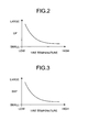
- FIG. 2 is a diagram explaining a relationship between a temperature of a tire and cornering power
- FIG. 3 is a diagram explaining a relationship between a temperature of a tire and self-aligning power
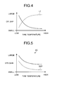
- FIG. 4 is a diagram explaining one example of a relationship between a tire characteristic and a degree of suppressing a behavior change
- FIG. 5 is a diagram illustrating one example of an EPS gain map
- FIG. 6 is a flowchart illustrating one example of EPS control.
- a vehicle control system 1 is mounted to a vehicle 2 for controlling the vehicle 2 as illustrated in FIG. 1 , and it is a vehicle behavior control device for controlling the behavior of the vehicle 2.
- the vehicle control system 1 typically varies the characteristic of the vehicle 2 based upon a temperature of a tire 4 on a wheel 3, thereby suppressing variation in the driving feeling involved with the change in the temperature of the tire 4, and preventing a drive's feeling of strangeness during the driving.
- the vehicle 2 includes a front-left wheel 3FL, a front-right wheel 3FR, a rear-left wheel 3RL, and a rear-right wheel 3RR as the wheels 3. When it is unnecessary to distinguish these wheels, they are merely referred to as the wheel 3. Power generated from a drive source (prime mover), e.g., an internal combustion engine or electric motor, is applied to the wheel 3 (e.g., a front-left wheel 3FL, and a front-right wheel 3FR), so that the vehicle 2 generates drive force [N] on a contact surface between the wheel 3 and a road surface, and hence, the vehicle 2 can run.
- a drive source primary mover
- the wheel 3 e.g., a front-left wheel 3FL, and a front-right wheel 3FR
- the wheel 3 (e.g., the front-left wheel 3FL and the front-right wheel 3FR) serving as a steered wheel can be steered, whereby the vehicle 2 can turn.
- a tire characteristic including cornering power (hereinafter referred to as "CP”, unless otherwise specified) or self-aligning power (hereinafter referred to as "SAP”, unless otherwise specified) of the tire 4 mounted to the wheel 3 tends to have relatively high temperature dependency. Therefore, the tire characteristic of the tire 4, such as CP or SAP, varies according to the temperature of the tire 4, even in the same tire 4.
- the CP of the tire 4 corresponds to cornering force CF per a unit slip angle (sideslip angle) ⁇ illustrated in FIG. 1 .
- the slip angle ⁇ is an angle made by the advancing direction of the tire 4 and the center plane of the tire.
- the cornering force CF is component force applied to the direction perpendicular to the advancing direction of the tire during the cornering (turn) of the vehicle 2.
- the SAP of the tire 4 corresponds to self-aligning torque SAT per the unit slip angle ⁇ illustrated in FIG. 1 .
- the self-aligning torque SAT is a moment around the contact point of the tire 4 (around a vertical axis), and corresponds to restoring force for returning the steering wheel 5 to the straight position.
- an abscissa axis indicates a tire temperature
- an ordinate axis indicates CP of the tire 4.
- an abscissa axis indicates a tire temperature
- an ordinate axis indicates SAP of the tire 4.
- the vehicle 2 when the CP or SAP varies due to the change in the temperature of the tire 4, the vehicle 2 might cause a variation in a driving feeling of a driver driving the vehicle 2, for example. Specifically, the vehicle 2 might provide a different driving feeling to the driver between a period of starting the drive when the tire 4 is cold, and a period of a predetermined time elapsed from the start of the drive when the tire 4 is warm.
- the motion of the vehicle 2 tends to be large with respect to an operation input or disturbance input, having an equivalent amount, i.e., the behavior of the vehicle 2 tends to be easily changed, as the CP and SAP reduces because of the increased temperature of the tire 4.
- the vehicle control system 1 of the present embodiment changes the characteristic of the vehicle 2 to suppress more the behavior change of the vehicle 2 to the equivalent input, as the temperature of the tire 4 relatively increases.
- the vehicle control system 1 changes the characteristic of the vehicle 2 to allow more the behavior change of the vehicle 2 to the equivalent input, as the temperature of the tire 4 relatively decreases.
- the vehicle control system 1 increases a degree L1 of suppressing the behavior change of the vehicle 2 with the increase in the tire temperature, in order to compensate the deterioration in the tire characteristic (CP, SAP, etc.) caused by the increased tire temperature by the change in the characteristic of the vehicle.
- a later-described ECU 8 increases the degree of suppressing the behavior change of the vehicle 2 by a later-described actuator, as the temperature of the tire detected by a later-described temperature sensor 7 is high, and decreases the degree of suppressing the behavior change of the vehicle 2 by the actuator, as the temperature of the tire detected by the temperature sensor 7 is low.
- the vehicle control system 1 prevents the generation of difference between a driving feeling during the driving with the tire 4 having low temperature, and a driving feeling during the driving with the tire 4 having high temperature, thereby suppressing the variation in the driving feeling.
- the vehicle control system 1 includes an electronic power steering (EPS) device (hereinafter referred to as "EPS device", unless otherwise specified) 6 serving as the actuator as illustrated in FIG. 1 .
- EPS device electronic power steering
- the ECU 8 serving as the control device controls the EPS device 6 according to the temperature of the tire 4, whereby the vehicle control system 1 suppresses the variation in the driving feeling.
- the vehicle control system 1 includes the EPS device 6, the temperature sensor 7 serving as a temperature detecting device, and the ECU 8 serving as the control device.
- the temperature sensor 7 detects the temperature of the tire 4 on the wheel 3 of the vehicle 2, and a thermocouple or thermistor can be used for the temperature sensor 7. More specifically, the temperature sensor 7 detects the temperature in the tread of the tire 4, e.g., the temperature of a carcass layer, a belt layer, or a tread rubber, which are the components in the tread. Preferably, the temperature sensor 7 detects the temperature in the tread rubber between the tread surface of the tire 4 and the top surface of the belt layer. In the present embodiment, only one temperature sensor 7 is illustrated. However, the temperature sensor 7 may be provided for each of four wheels 3. The temperature sensor 7 is electrically connected to the ECU 8, and transmits a signal of the detected temperature of the tire 4 to the ECU 8. A contactless temperature sensor utilizing infrared ray can be used as the temperature sensor 7. The temperature sensor 7 may detect the temperature of a wheel to which the tire is mounted, and detect and estimate the temperature in the tread of the tire 4 based upon the detected temperature, for example.
- the ECU 8 controls the EPS device 6 to adjust the assist torque based upon the steering torque to the steering wheel 5 detected by the torque sensor included in the EPS device 6.
- the wheel 3 serving as the steered wheel is steered with a predetermined turning amount by axial force generated on a tie rod with a magnitude according to the steering torque inputted to the steering wheel by the driver and the assist torque generated by the EPS device 6.
- the ECU 8 decreases the assist torque by the EPS device 6 to the equivalent steering input, as the temperature of the tire 4 relatively increases.
- the degree of suppressing the behavior change of the vehicle 2 by the EPS device 6 can be increased, which prevents the behavior change in the turning direction of the vehicle 2 to the equivalent operation input from becoming large, compared to the case where the temperature of the tire 4 is low.
- the behavior change to the equivalent operation input during when the temperature of the tire 4 is relatively high and the behavior change to the equivalent operation input during when the temperature of the tire 4 is relatively low can be set to be almost the same.
- FIG. 7 is a schematic diagram illustrating a schematic configuration of a vehicle control system according to a second embodiment
- FIG. 8 is a diagram explaining a relationship between a temperature of a tire and normalized cornering power
- FIG. 9 is a flowchart illustrating one example of VGRS control
- FIG. 10 is a diagram illustrating one example of a CP/W map.
- the configuration of the actuator is different from that in the first embodiment. The redundant description for the configuration, operation, and effect same as those in the first embodiment will be skipped as much as possible (the same applies to the embodiments described later).
- a vehicle control system 201 includes a variable gear ratio steering (VGRS) device (hereinafter referred to as "VGRS device", unless otherwise specified) 206 as the actuator as illustrated in FIG. 7 .
- VGRS device variable gear ratio steering
- the vehicle control system 201 compensates the deterioration in the tire characteristic caused by the increased temperature of the tire by the change in the vehicle characteristic, in order to suppress the variation in the driving feeling.
- the VGRS device 206 is arranged on a steering system between the steering wheel 5 and the wheel 3 (e.g., the front-left wheel 3FL, the front-right wheel 3FR) serving as the steered wheel, and it can change a steering gear ratio (hereinafter referred to as "gear ratio", unless otherwise specified) of the steering wheel 5.
- the VGRS device 206 changes the gear ratio according to the driving condition, thereby being capable of changing the turning amount (steering angle) of the steered wheel or the turning speed (steering speed) to the input of the steering torque to the steering wheel 5.
- the VGRS device 206 is connected to the ECU 8, and controlled by the ECU 8.
- the VGRS device 206 can adjust the behavior of the vehicle 2, in other words.
- the VGRS device 206 can change the degree of suppressing the behavior change of the vehicle 2.
- the VGRS device 206 can change the degree of the behavior change of the vehicle 2, i.e., the degree of suppressing the behavior change of the vehicle 2, by changing the steering characteristic of the vehicle 2.
- the VGRS device 206 changes the gear ratio to change the steering characteristic of the vehicle 2, thereby being capable of changing a balance between slip angles of the front-left wheel 3FL and the front-right wheel 3FR and slip angles of the rear-left wheel 3RL and the rear-right wheel 3RR during when the equivalent steering torque is applied to the steering wheel 5 by the driver.
- the VGRS device 206 can adjust the degree of suppressing the behavior change of the vehicle 2.
- the ECU 8 in the present embodiment controls the VGRS device 206 according to the temperature of the tire 4 detected by the temperature sensor 7, i.e., based upon the CP of the wheel 3 that is according to the temperature of the tire 4 detected by the temperature sensor 7 and that reduces with the increase in the temperature of the tire 4, thereby changing the degree of suppressing the behavior change of the vehicle 2.
- the ECU 8 controls the VGRS device 206 to adjust the slip angle balance between the front wheels and rear wheels, thereby increasing the degree of suppressing the behavior change of the vehicle 2 by the VGRS device 206, compared to the case where the temperature of the tire 4 is relatively low.
- normalized CP normalized cornering power
- the normalized CP can be expressed by "CP/W”, when the axle load is defined as "W”.
- the range of the decrease in the normalized CP with the temperature rise of the tire 4 is different depending upon the axle load W, and hence, it is different between the front wheels and the rear wheels of the vehicle 2.
- a stability factor Kh has been known as a parameter indicating the turning characteristic of the vehicle 2 or driving stability.
- the stability factor Kh can be represented by a formula (1) described below, for example.
- "g” represents gravitational acceleration
- "1” represents a wheel base of the vehicle 2
- "equivalent CPf” represents an equivalent CP on the front wheels of the vehicle 2
- "equivalent CPr” represents an equivalent CP on the rear wheels of the vehicle 2
- Wf represents the axle load on the front wheels of the vehicle 2
- “Wr” represents the axle load on the rear wheels of the vehicle 2.
- “equivalent CPf/Wf” and “equivalent CPr/Wr” respectively correspond to the normalized equivalent CP.
- Kh 1 / g ⁇ l ⁇ 1 / equivalent CPf / Wf - 1 / equivalent CPr / Wr
- the above-mentioned equivalent CP is the CP considering the influence of a so-called roll steer and compliance steer, and in other words, the CP when the roll characteristic or suspension characteristic of the vehicle 2 is supposed to be taken into the tire characteristic.
- the suspension of the vehicle 2 is a suspension device present between the wheel 3 and a vehicle body 2A, and eases impact or vibration transmitted to the vehicle body 2A from the road surface.
- the roll steer of the vehicle 2 corresponds to a toe angle change (or slip angle change) generated with a roll motion of the vehicle body 2A of the vehicle 2 in the roll direction
- the compliance steer of the vehicle 2 corresponds to a toe angle change (or slip angle change) generated due to a deformation of each unit such as a suspension bush of the vehicle 2.
- the motion of the vehicle 2 in the yaw direction increases by the amount of the relative decrease in the stability factor Kh, i.e., the behavior change of the vehicle 2 in the yaw direction might increase, compared to the case in which the temperature of the tire 4 is low.
- the vehicle control system 201 controls the gear ratio of the VGRS device 206 to adjust the slip angle balance between the front wheels and the rear wheels, thereby increasing the degree of suppressing the behavior change of the vehicle by the VGRS device 206, compared to the case in which the temperature of the tire 4 is relatively low. Accordingly, the vehicle control system 201 can appropriately adjust the balance between the equivalent CPf and the equivalent CPr in the formula (1).
- the ECU 8 controls the gear ratio of the VGRS device 206 to equivalently adjust the [CPf/Wf] on the front wheel according to the change in the temperature of the tire 4, in order that the stability factor Kh becomes constant with respect to the change in the temperature of the tire 4.
- the vehicle control system 201 controls the VGRS device 206 to adjust the slip angle balance between the front wheels and the rear wheels according to the change in the temperature of the tire 4, it can appropriately adjust the balance between the equivalent CPf and the equivalent CPr according to the change in the normalized CP, even if the normalized CP is changed due to the change in the temperature of the tire 4.
- the vehicle control system 201 can make the stability factor Kh when the temperature of the tire 4 is relatively high and the stability factor Kh when the temperature of the tire 4 is relatively low almost equal to each other. Therefore, the vehicle control system 201 can stabilize the stability factor Kh, regardless of the temperature of the tire 4. Consequently, the vehicle control system 201 can perform the temperature compensation of the stability factor Kh to the temperature dependency of the tire characteristic in order to prevent the stability factor Kh from varying according to the temperature.
- the vehicle control system 201 can stabilize the stability factor Kh, regardless of the temperature of the tire 4. Therefore, the vehicle control system 201 can suppress the behavior change of the vehicle, in the present embodiment, can suppress the increase in the motion in the yaw direction, to the equivalent operation input, compared to the case where the temperature is low. As a result, the vehicle control system 201 can make the behavior change when the temperature of the tire is relatively high and the behavior change when the temperature of the tire is relatively low almost equal to each other to the equivalent operation input.
- the vehicle control system 201 can suppress the variation in the driving feeling involved with the change in the temperature of the tire 4, and hence, can suppress the sense of strangeness of the driver during the drive, for example.
- the vehicle control system 201 includes the VGRS device 206 that can adjust the behavior of the vehicle 2, the temperature sensor 7 that detects the temperature of the tire 4 on the wheel 3 of the vehicle 2, and the ECU 8 that controls the VGRS device 206 according to the temperature of the tire 4 detected by the temperature sensor 7 so as to change the degree of suppressing the behavior change of the vehicle 2 by the VGRS device 206. Accordingly, the vehicle control system 201 and the ECU 8 can suppress the variation in the driving feeling.
- FIG. 11 is a schematic diagram illustrating a schematic configuration of a vehicle control system according to a third embodiment
- FIG. 12 is a flowchart illustrating one example of ARS control.
- the structure of the actuator is different from that in the second embodiment.
- the ARS device 306 can adjust the behavior of the vehicle 2, in other words.
- the ARS device 306 can change the degree of suppressing the behavior change of the vehicle 2.
- the ARS device 306 adjusts the steering angles and the turning amounts of the rear-left wheel 3RL and the rear-right wheel 3RR to the steering torque applied to the steering wheel by the driver, thereby being capable of changing the slip angle balance between the slip angles of the front-left wheel 3FL and the front-right wheel 3FR and the slip angles of the rear-left wheel 3RL and the rear-right wheel 3RR when the equivalent steering torque is applied to the steering wheel 5 by the driver.
- the ARS device 306 can change the degree of suppressing the behavior change of the vehicle 2.
- the ECU 8 increases the degree of suppressing the behavior change of the vehicle 2 by the ARS device 306, as the temperature of the tire 4 relatively increases, and decreases the degree of suppressing the behavior change of the vehicle 2 by the ARS device 306, as the temperature of the tire 4 relatively decreases.
- the vehicle control system 301 can make the stability factor Kh when the temperature of the tire 4 is relatively high and the stability factor Kh when the temperature of the tire 4 is relatively low almost equal to each other. Therefore, the vehicle control system 301 can perform the temperature compensation of the stability factor Kh to the temperature dependency of the tire characteristic in order to prevent the stability factor Kh from varying according to the temperature.
- the vehicle control system 301 can make the behavior change when the temperature of the tire is relatively high and the behavior change when the temperature of the tire is relatively low, i.e., the motions in the yaw direction, almost equal to each other to the equivalent operation input. Accordingly, the vehicle control system 301 can suppress the variation in the driving feeling involved with the change in the temperature of the tire 4, and hence, can suppress the sense of strangeness of the driver during the drive, for example.
- the ECU 8 acquires the temperature of the tire 4 detected by the temperature sensor 7 (ST301). Then, the ECU 8 calculates the normalized CPf of the front wheel from the temperature of the tire 4 of the front wheel acquired in ST301 based upon the CP/W map m2 (see FIG. 10 ) for the front wheel and the normalized CPr of the rear wheel from the temperature of the tire 4 on the rear wheel acquired in ST301 based upon the CP/W map m2 for the rear wheel (ST302).
- the ECU 8 then acquires the target normalized CPrt of the rear wheel based upon the normalized CPf acquired in ST302 and the target stability factor Kht (ST303).
- the ECU 8 controls the ARS device 306 based upon the target rear-wheel steering angle acquired in ST304 to adjust the slip angle balance between the front wheel and the rear wheel by the ARS device 306, thereby adjusting the balance between the equivalent CPf and the equivalent CPr (ST305). Then the ECU 8 ends the current control cycle, and moves to the next control cycle.
- the vehicle control system 301 includes the ARS device 306 that can adjust the behavior of the vehicle 2, the temperature sensor 7 that detects the temperature of the tire 4 on the wheel 3 of the vehicle 2, and the ECU 8 that controls the ARS device 306 according to the temperature of the tire 4 detected by the temperature sensor 7 so as to change the degree of suppressing the behavior change of the vehicle 2 by the ARS device 306. Accordingly, the vehicle control system 301 and the ECU 8 can suppress the variation in the driving feeling.
- FIG. 13 is a schematic diagram illustrating a schematic configuration of a vehicle control system according to a fourth embodiment
- FIG. 14 is a diagram illustrating one example of an ARS gain
- FIG. 15 is a flowchart illustrating one example of ARS control.
- the structure of the actuator is different from that in the third embodiment.
- a vehicle control system 401 includes an ARS device 306 as the actuator as illustrated in FIG. 13 .
- the ECU 8 serving as the control device controls the ARS device 306 according to the temperature of the tire 4, whereby the vehicle control system 301 compensates the deterioration in the tire characteristic due to the increased tire temperature by the change in the characteristic of the vehicle, so as to suppress the variation in the driving feeling.
- the ARS device 306 can change the slip angles of the rear-left wheel 3RL and the rear-right wheel 3RR of the vehicle 2 by adjusting the steering angles and the turning amounts of the rear-left wheel 3RL and the rear-right wheel 3RR to the steering torque applied to the steering wheel 5 by the driver.
- the ARS device 306 can adjust the degree of suppressing the behavior change of the vehicle 2.
- the ECU 8 increases the degree of suppressing the behavior change of the vehicle 2 by the ARS device 306, compared to the case where the temperature of the tire 4 is relatively low. Specifically, in this case, the ECU 8 controls the ARS device 306 to increase the slip angle of the rear wheel of the vehicle 2, compared to the case where the temperature of the tire 4 is relatively low, thereby increasing the degree of suppressing the behavior change of the vehicle 2 by the ARS device 306 to the equivalent input.
- the ECU 8 decreases the degree of suppressing the behavior change of the vehicle 2 by the ARS device 306, compared to the case where the temperature of the tire 4 is relatively high. Specifically, in this case, the ECU 8 controls the ARS device 306 to decrease the slip angle of the rear wheel of the vehicle 2, compared to the case where the temperature of the tire 4 is relatively high, thereby decreasing the degree of suppressing the behavior change of the vehicle 2 by the ARS device 306 to the equivalent input.
- the ECU 8 obtains an ARS gain based upon an ARS gain map m3 illustrated in FIG. 14 , for example.
- an abscissa axis indicates the temperature of the tire 4
- an ordinate axis indicates the ARS gain.
- the ARS device 306 increases the rear-wheel steering angle of the vehicle 2 to increase the slip angle of the rear wheel, as the ARS gain increases, and decreases the rear-wheel steering angle of the vehicle 2 to decrease the slip angle of the rear wheel, as the ARS gain decreases.
- the ARS gain map m3 indicates the relationship between the temperature of the tire 4 (in other words, the CP according to the tire temperature) and the ARS gain.
- the relationship between the temperature of the tire and the ARS gain is set in advance in the ARS gain map m3 in consideration of the temperature dependency of the tire characteristic, and with this state, the ARS gain map m3 is stored in a storage unit of the ECU 8.
- the ARS gain map m3 the ARS gain increases with the increase in the tire temperature, i.e., with the decrease in the CP.
- the ECU 8 acquires the ARS gain from the temperature of the tire 4 detected by the temperature sensor 7 based upon the ARS gain map m3.
- the ECU 8 controls the ARS device 306 to adjust the slip angle of the rear wheel of the vehicle 2 based upon the acquired ARS gain, thereby adjusting the degree of suppressing the behavior change of the vehicle 2.
- the ECU 8 increases the slip angle of the rear wheel of the vehicle 2 by the ARS device 306, and as the temperature of the tire 4 relatively decreases, the ECU 8 decreases the slip angle of the rear wheel of the vehicle 2 by the ARS device 306.
- the ECU 8 increases the degree of suppressing the behavior change of the vehicle 2 by the ARS device 306, as the temperature of the tire 4 relatively increases, and decreases the degree of suppressing the behavior change of the vehicle 2 by the ARS device 306, as the temperature of the tire 4 relatively decreases.
- the equivalent CP of the rear wheel of the vehicle 2 when the roll characteristic or suspension characteristic of the vehicle 2 considering the influence of a so-called roll steer and compliance steer is supposed to be taken into the tire characteristic might be reduced. Therefore, when disturbance input such as an operation input or crosswind is exerted on the vehicle body 2A in case where the temperature of the tire 4 is relatively high, the motion of the vehicle 2 in the yaw direction increases by the relative decrease in the equivalent CP on the rear wheel, compared to the case where the temperature of the tire 4 is low, i.e., the behavior change of the vehicle 2 in the yaw direction might increase.
- the vehicle control system 401 when the temperature of the tire 4 detected by the temperature sensor 7 becomes relatively high, the vehicle control system 401 according to the present embodiment increases the rear-wheel steering angle by the ARS device 306 to increase the slip angle of the rear wheel, thereby increasing the degree of suppressing the behavior change of the vehicle by the ARS device 306. Therefore, the vehicle control system 401 can prevent the behavior change of the vehicle 2 from increasing to the equivalent input, compared to the case in which the temperature of the tire 4 is relatively low.
- the ECU 8 acquires the temperature of the tire 4 detected by the temperature sensor 7 (ST401).
- the ECU 8 obtains the ARS gain based upon the ARS gain map m3 illustrated in FIG. 14 , for example, based upon the temperature of the tire 4 on the rear wheel acquired in ST401 (ST402).
- the ECU 8 controls the ARS device 306 based upon the ARS gain determined in ST402 to adjust the rear-wheel steering angle by the ARS device 306 for adjusting the slip angle of the rear wheel (ST403), ends the current control cycle, and moves to the next control cycle.
- the compliance steer generated on the rear-left wheel 3RL and the rear-right wheel 3RR is adjusted, whereby the CP on the rear wheels is equivalently adjusted in order that the equivalent CP on the rear wheel of the vehicle 2 becomes constant with respect to the change in the temperature of the tire 4.
- the vehicle control system 501 controls the bush stiffness by the active bush device 506 for adjusting the slip angle of the rear wheel according to the change in the temperature of the tire 4, it can appropriately adjust the slip angle of the rear wheel according to the change in the CP to make the equivalent CP on the rear wheel of the vehicle 2 almost constant, even if the CP is changed due to the change in the temperature of the tire 4.
- the vehicle control system 501 can make the equivalent CP on the rear wheel when the temperature of the tire 4 is relatively high and the equivalent CP on the rear wheel when the temperature of the tire 4 is relatively low almost equal to each other. Therefore, the vehicle control system 501 can perform the temperature compensation of the equivalent CP on the rear wheel to the temperature dependency of the tire characteristic in order to prevent the equivalent CP on the rear wheel from varying according to the temperature.
- the vehicle control system 501 can make the behavior change when the temperature of the tire is relatively high and the behavior change when the temperature of the tire is relatively low, i.e., the motions in the yaw direction, almost equal to each other to the equivalent operation input. Accordingly, the vehicle control system 501 can suppress the variation in the driving feeling involved with the change in the temperature of the tire 4, and hence, can suppress the sense of strangeness of the driver during the drive, for example.
- the active bush gain map m4 in FIG. 19 may describe the relationship between the CP according to the temperature of the tire 4 and the active bush gain.
- the ECU 8 acquires the temperature of the tire 4 in ST501, and then, estimates the current CP based upon the temperature of the tire.
- the ECU 8 may calculate the difference (deviation) between a reference CP that is a reference set in advance and the estimated CP, and may calculate the active bush gain by using this difference and the map (e.g., active bush gain ⁇ reference CP - estimated CP).
- the vehicle control system 501 includes the active bush device 506 that can adjust the behavior of the vehicle 2, the temperature sensor 7 that detects the temperature of the tire 4 on the wheel 3 of the vehicle 2, and the ECU 8 that controls the active bush device 506 according to the temperature of the tire 4 detected by the temperature sensor 7 so as to change the degree of suppressing the behavior change of the vehicle 2 by the active bush device 506. Accordingly, the vehicle control system 501 and the ECU 8 can suppress the variation in the driving feeling.
- a vehicle control system 601 includes an adjusting device 606 as illustrated in FIG. 21 . Since the ECU 8 serving as the control device controls the adjusting device 606 according to the temperature of the tire 4, the vehicle control system 601 keeps the tire temperature appropriate, thereby effectively suppressing the variation in the driving feeling.
- the adjusting device 606 can adjust the temperature of the tire 4.
- the adjusting device 606 ejects air from an air conditioner or exhaust gas to a tire housing of the tire 4 to adjust the tire temperature, for example.
- the adjusting device 606 blows the air or exhaust gas to the tire 4 to increase the tire temperature, or keep the tire temperature to a temperature equal to or higher than a predetermined temperature.
- the adjusting device 606 is connected to the ECU 8, and controlled by the ECU 8.
Landscapes
- Engineering & Computer Science (AREA)
- Mechanical Engineering (AREA)
- Transportation (AREA)
- Chemical & Material Sciences (AREA)
- Combustion & Propulsion (AREA)
- Automation & Control Theory (AREA)
- Physics & Mathematics (AREA)
- Mathematical Physics (AREA)
- Steering Control In Accordance With Driving Conditions (AREA)
- Control Of Driving Devices And Active Controlling Of Vehicle (AREA)
- Vehicle Body Suspensions (AREA)
- Regulating Braking Force (AREA)
Abstract
Description
- The present invention relates to a vehicle control system and a control device.
- As a conventional vehicle control system or a control device,
Patent Literature 1 describes a vehicle motion control device that estimates a temperature and an amount of deformation of a tire by using a camera mounted to a vehicle body, determines a turning state of the vehicle, e.g., determines whether understeer or oversteer occurs or not, based upon the obtained temperature and the amount of deformation of the tire, and decides a control amount of a steering angle. - Patent Literature 1: Japanese Patent Application Laid-open No.
2006-142895 - The vehicle motion control device described in
Patent Literature 1 has a room for improvement to suppress variation in driving feeling, for example. - The present invention is accomplished in view of the above-mentioned circumstance, and aims to provide a vehicle control system and a control device that can suppress variation in driving feeling.
- In order to achieve the above mentioned object, a vehicle control system according to the present invention includes an actuator capable of adjusting a behavior of a vehicle; a temperature detecting device configured to detect a temperature of a tire on a wheel of the vehicle; and a control device configured to control the actuator according to the temperature of the tire detected by the temperature detecting device so as to change a degree of suppressing a behavior change of the vehicle by the actuator.
- Further, in the vehicle control system, it is possible to configure that the control device increases the degree of suppressing the behavior change of the vehicle by the actuator, when the temperature of the tire detected by the temperature detecting device is relatively high, compared to a case where the temperature of the tire is relatively low.
- Further, in the vehicle control system, it is possible to configure that the control device decreases the degree of suppressing the behavior change of the vehicle by the actuator, when the temperature of the tire detected by the temperature detecting device is relatively low, compared to a case where the temperature of the tire is relatively high.
- Further, in the vehicle control system, it is possible to configure that the control device increases the degree of suppressing the behavior change of the vehicle by the actuator, as the temperature of the tire detected by the temperature detecting device is high, and decreases the degree of suppressing the behavior change of the vehicle by the actuator, as the temperature of the tire detected by the temperature detecting device is low.
- Further, in the vehicle control system, it is possible to configure that the temperature detecting device detects a temperature in a tread of the tire.
- Further, in the vehicle control system, it is possible to configure that the actuator can change the degree of suppressing the behavior change of the vehicle by changing a steering characteristic of the vehicle.
- Further, in the vehicle control system, it is possible to configure that the actuator can change the degree of suppressing the behavior change of the vehicle by changing a suspension characteristic of the vehicle.
- Further, in the vehicle control system, it is possible to configure that the actuator can steer the wheel according to a steering torque inputted to a steering member, and the control device controls the actuator so as to decrease a turning amount of the wheel to the steering torque inputted to the steering member, when the temperature of the tire detected by the temperature detecting device is relatively high, compared to the case in which the temperature of the tire is relatively low.
- Further, in the vehicle control system, it is possible to configure that the actuator can change a slip angle balance between a slip angle of a front wheel and a slip angle of a rear wheel of the vehicle, and the control device controls the actuator so as to adjust the slip angle balance, and increases the degree of suppressing the behavior change of the vehicle by the actuator, when the temperature of the tire detected by the temperature detecting device is relatively high, compared to the case in which the temperature of the tire is relatively low.
- Further, in the vehicle control system, it is possible to configure that the actuator can change the slip angle of the rear wheel of the vehicle, and the control device controls the actuator so as to increase the slip angle of the rear wheel of the vehicle, when the temperature of the tire detected by the temperature detecting device is relatively high, compared to the case in which the temperature of the tire is relatively low.
- Further, in the vehicle control system, it is possible to configure that the control device controls the actuator so as to change the degree of suppressing the behavior change of the vehicle based on cornering power or self-aligning power of the wheel that reduces with the increase in the temperature of the tire.
- Further, in the vehicle control system, it is possible to further include an adjusting device capable of adjusting the temperature of the tire, and it is possible to configure that the control device controls the adjusting device so as to adjust the temperature of the tire to be a temperature equal to or higher than a predetermined temperature set in advance.
- In order to achieve the above mentioned object, a vehicle control system according to the present invention includes an adjusting device capable of adjusting a temperature of a tire on a wheel of a vehicle; and a control device configured to control the adjusting device so as to adjust the temperature of the tire to be a temperature equal to or higher than a predetermined temperature set in advance.
- In order to achieve the above mentioned object, a control device according to the present invention that controls an actuator, which can adjust a behavior of a vehicle, according to a temperature of a tire detected by a temperature detecting device that detects the temperature of the tire on a wheel of the vehicle, in order to change a degree of suppressing a behavior change of the vehicle by the actuator.
- In order to achieve the above mentioned object, a control device according to the present invention that controls an adjusting device that can adjust a temperature of a tire on a wheel of a vehicle, in order to adjust the temperature of the tire to be a temperature equal to or higher than a predetermined temperature set in advance. Advantageous Effects of Invention
- The vehicle control system and the control device according to the present invention provides an effect of suppressing the variation in driving feeling.
-
-
FIG. 1 is a schematic diagram illustrating a schematic configuration of a vehicle control system according to a first embodiment. -
FIG. 2 is a diagram explaining a relationship between a temperature of a tire and cornering power. -
FIG. 3 is a diagram explaining a relationship between a temperature of a tire and self-aligning power. -
FIG. 4 is a diagram explaining one example of a relationship between a tire characteristic and a degree of suppressing a behavior change. -
FIG. 5 is a diagram illustrating one example of an EPS gain map. -
FIG. 6 is a flowchart illustrating one example of EPS control. -
FIG. 7 is a schematic diagram illustrating a schematic configuration of a vehicle control system according to a second embodiment. -
FIG. 8 is a diagram explaining a relationship between a temperature of a tire and normalized cornering power. -
FIG. 9 is a flowchart illustrating one example of VGRS control. -
FIG. 10 is a diagram illustrating one example of a CP/W map. -
FIG. 11 is a schematic diagram illustrating a schematic configuration of a vehicle control system according to a third embodiment. -
FIG. 12 is a flowchart illustrating one example of ARS control. -
FIG. 13 is a schematic diagram illustrating a schematic configuration of a vehicle control system according to a fourth embodiment. -
FIG. 14 is a diagram illustrating one example of an ARS gain. -
FIG. 15 is a flowchart illustrating one example of ARS control. -
FIG. 16 is a schematic diagram illustrating a schematic configuration of a vehicle control system according to a fifth embodiment. -
FIG. 17 is a schematic diagram illustrating a schematic configuration of an active bush device. -
FIG. 18 is a diagram illustrating one example of a relationship between a bush temperature and bush stiffness. -
FIG. 19 is a diagram illustrating one example of an active bush gain map. -
FIG. 20 is a flowchart illustrating one example of active bush control. -
FIG. 21 is a schematic diagram illustrating a schematic configuration of a vehicle control system according to a sixth embodiment. -
FIG. 22 is a diagram explaining a stabilized region of a tire characteristic. - Embodiments of the present invention will be described below in detail with reference to the drawings. The present invention is not limited by these embodiments. The components in the embodiments described below include those that can be replaced or easily made by a person skilled in the art, and those substantially equivalent.
-
FIG. 1 is a schematic diagram illustrating a schematic configuration of a vehicle control system according to a first embodiment,FIG. 2 is a diagram explaining a relationship between a temperature of a tire and cornering power,FIG. 3 is a diagram explaining a relationship between a temperature of a tire and self-aligning power,FIG. 4 is a diagram explaining one example of a relationship between a tire characteristic and a degree of suppressing a behavior change,FIG. 5 is a diagram illustrating one example of an EPS gain map, andFIG. 6 is a flowchart illustrating one example of EPS control. - A
vehicle control system 1 according to the present embodiment is mounted to avehicle 2 for controlling thevehicle 2 as illustrated inFIG. 1 , and it is a vehicle behavior control device for controlling the behavior of thevehicle 2. Thevehicle control system 1 typically varies the characteristic of thevehicle 2 based upon a temperature of atire 4 on awheel 3, thereby suppressing variation in the driving feeling involved with the change in the temperature of thetire 4, and preventing a drive's feeling of strangeness during the driving. - The
vehicle 2 includes a front-left wheel 3FL, a front-right wheel 3FR, a rear-left wheel 3RL, and a rear-right wheel 3RR as thewheels 3. When it is unnecessary to distinguish these wheels, they are merely referred to as thewheel 3. Power generated from a drive source (prime mover), e.g., an internal combustion engine or electric motor, is applied to the wheel 3 (e.g., a front-left wheel 3FL, and a front-right wheel 3FR), so that thevehicle 2 generates drive force [N] on a contact surface between thewheel 3 and a road surface, and hence, thevehicle 2 can run. When a driver operates to rotate asteering wheel 5 serving as a steering member (steering operation), the wheel 3 (e.g., the front-left wheel 3FL and the front-right wheel 3FR) serving as a steered wheel can be steered, whereby thevehicle 2 can turn. - The longitudinal direction of the
vehicle 2 described below is the direction along the traveling direction of thevehicle 2, and the lateral direction of thevehicle 2 is the widthwise direction of thevehicle 2 perpendicular to the longitudinal direction and the vertical direction. A roll direction is a direction around a longitudinal axis that is an axis along the longitudinal direction of the vehicle, and a yaw direction is a direction around a vertical axis along the vertical direction of the vehicle. - A tire characteristic including cornering power (hereinafter referred to as "CP", unless otherwise specified) or self-aligning power (hereinafter referred to as "SAP", unless otherwise specified) of the
tire 4 mounted to thewheel 3 tends to have relatively high temperature dependency. Therefore, the tire characteristic of thetire 4, such as CP or SAP, varies according to the temperature of thetire 4, even in thesame tire 4. - The CP of the
tire 4 corresponds to cornering force CF per a unit slip angle (sideslip angle) β illustrated inFIG. 1 . The slip angle β is an angle made by the advancing direction of thetire 4 and the center plane of the tire. The cornering force CF is component force applied to the direction perpendicular to the advancing direction of the tire during the cornering (turn) of thevehicle 2. The SAP of thetire 4 corresponds to self-aligning torque SAT per the unit slip angle β illustrated inFIG. 1 . The self-aligning torque SAT is a moment around the contact point of the tire 4 (around a vertical axis), and corresponds to restoring force for returning thesteering wheel 5 to the straight position. When thetire 4 rolls with the predetermined slip angle β, a point of load of the cornering force CF is shifted from the center of the contact point of thetire 4. Therefore, force (torque) is exerted in the direction of reducing the slip angle β around the center of the contact point. This force corresponds to the self-aligning force SAT. The self-aligning torque SAT affects straight line stability and heaviness of thesteering wheel 5. - In
FIG. 2 , an abscissa axis indicates a tire temperature, and an ordinate axis indicates CP of thetire 4. InFIG. 3 , an abscissa axis indicates a tire temperature, and an ordinate axis indicates SAP of thetire 4. As illustrated inFIG. 2 , if the vertical load is equal, a tread rubber of thetire 4 becomes soft to be easily deformed, as the tire temperature becomes higher. Therefore, there is a tendency that the higher the tire temperature becomes, the smaller the CP of thetire 4 becomes, and the lower the tire temperature becomes, the larger the CP of thetire 4 becomes. Similarly, if the vertical load is equal, there is a tendency that the higher the tire temperature becomes, the smaller the SAP of thetire 4 becomes, and the lower the tire temperature becomes, the larger the SAP of thetire 4 becomes. - As a result, when the CP or SAP varies due to the change in the temperature of the
tire 4, thevehicle 2 might cause a variation in a driving feeling of a driver driving thevehicle 2, for example. Specifically, thevehicle 2 might provide a different driving feeling to the driver between a period of starting the drive when thetire 4 is cold, and a period of a predetermined time elapsed from the start of the drive when thetire 4 is warm. Typically, the motion of thevehicle 2 tends to be large with respect to an operation input or disturbance input, having an equivalent amount, i.e., the behavior of thevehicle 2 tends to be easily changed, as the CP and SAP reduces because of the increased temperature of thetire 4. - In view of this, the
vehicle control system 1 of the present embodiment changes the characteristic of thevehicle 2 to suppress more the behavior change of thevehicle 2 to the equivalent input, as the temperature of thetire 4 relatively increases. In other words, thevehicle control system 1 changes the characteristic of thevehicle 2 to allow more the behavior change of thevehicle 2 to the equivalent input, as the temperature of thetire 4 relatively decreases. Specifically, as illustrated inFIG. 4 , thevehicle control system 1 increases a degree L1 of suppressing the behavior change of thevehicle 2 with the increase in the tire temperature, in order to compensate the deterioration in the tire characteristic (CP, SAP, etc.) caused by the increased tire temperature by the change in the characteristic of the vehicle. In other words, in thevehicle control system 1, a later-describedECU 8 increases the degree of suppressing the behavior change of thevehicle 2 by a later-described actuator, as the temperature of the tire detected by a later-describedtemperature sensor 7 is high, and decreases the degree of suppressing the behavior change of thevehicle 2 by the actuator, as the temperature of the tire detected by thetemperature sensor 7 is low. By virtue of this process, thevehicle control system 1 prevents the generation of difference between a driving feeling during the driving with thetire 4 having low temperature, and a driving feeling during the driving with thetire 4 having high temperature, thereby suppressing the variation in the driving feeling. - In the present embodiment, the
vehicle control system 1 includes an electronic power steering (EPS) device (hereinafter referred to as "EPS device", unless otherwise specified) 6 serving as the actuator as illustrated inFIG. 1 . TheECU 8 serving as the control device controls theEPS device 6 according to the temperature of thetire 4, whereby thevehicle control system 1 suppresses the variation in the driving feeling. - Specifically, the
vehicle control system 1 includes theEPS device 6, thetemperature sensor 7 serving as a temperature detecting device, and theECU 8 serving as the control device. - The
EPS device 6 can steer thewheel 3, which is the steered wheel, in a predetermined turning amount according to the steering torque, which is steering force, inputted to thesteering wheel 5 serving as the steering member from a driver. TheEPS device 6 assists the driver's operation of thesteering wheel 5 by power such as the electric motor. TheEPS device 6 outputs assist torque that is steering assist force for assisting the steering torque inputted to thesteering wheel 5 by the driver, and steers the steered wheel (that is mechanically coupled to the steering wheel 5) by the steering torque and the assist torque. TheEPS device 6 applies the assist torque to a rotation shaft of thesteering wheel 5 to assist the driver's steering operation, for example. TheEPS device 6 is connected to theECU 8, and controlled by theECU 8. - In other words, the
EPS device 6 can adjust the behavior of thevehicle 2, and in the present embodiment, it can change the degree of suppressing the behavior change of thevehicle 2. TheEPS device 6 changes the steering characteristic of thevehicle 2, thereby being capable of changing the degree of the behavior change of thevehicle 2, i.e., the degree of suppressing the behavior change of thevehicle 2. TheEPS device 6 adjusts the degree of the assist to the steering torque applied to thesteering wheel 5 by the driver, thereby being capable of adjusting the turning amount of the steered wheel to the steering torque inputted to thesteering wheel 5, e.g., the amount of change of the turning angle of the steered wheel. By utilizing this, the degree of suppressing the behavior change of thevehicle 2 can be adjusted. - For example, the
EPS device 6 relatively decreases the assist torque (assist amount) when the equivalent steering torque is applied to thesteering wheel 5 by the driver, thereby being capable of relatively decreasing the turning amount of thewheel 3 to the equivalent steering torque. With this process, theEPS device 6 can relatively reduce the behavior change of thevehicle 2 to the equivalent steering torque. In other words, theEPS device 6 relatively decreases the assist torque, thereby being capable of increasing the degree of suppressing the behavior change of thevehicle 2 to the equivalent steering input. On the other hand, theEPS device 6 relatively increases the assist torque (assist amount) when the equivalent steering torque is applied to thesteering wheel 5 by the driver, thereby being capable of relatively increasing the turning amount of thewheel 3 to the equivalent steering torque. With this process, theEPS device 6 can relatively increase the behavior change of thevehicle 2 to the equivalent steering torque. In other words, theEPS device 6 relatively increases the assist torque, thereby being capable of decreasing the degree of suppressing the behavior change of thevehicle 2 to the equivalent steering input. - The
temperature sensor 7 detects the temperature of thetire 4 on thewheel 3 of thevehicle 2, and a thermocouple or thermistor can be used for thetemperature sensor 7. More specifically, thetemperature sensor 7 detects the temperature in the tread of thetire 4, e.g., the temperature of a carcass layer, a belt layer, or a tread rubber, which are the components in the tread. Preferably, thetemperature sensor 7 detects the temperature in the tread rubber between the tread surface of thetire 4 and the top surface of the belt layer. In the present embodiment, only onetemperature sensor 7 is illustrated. However, thetemperature sensor 7 may be provided for each of fourwheels 3. Thetemperature sensor 7 is electrically connected to theECU 8, and transmits a signal of the detected temperature of thetire 4 to theECU 8. A contactless temperature sensor utilizing infrared ray can be used as thetemperature sensor 7. Thetemperature sensor 7 may detect the temperature of a wheel to which the tire is mounted, and detect and estimate the temperature in the tread of thetire 4 based upon the detected temperature, for example. - The
ECU 8 controls the drive of each unit of thevehicle 2. TheECU 8 is an electric circuit mainly composed of known microcomputer including a CPU, ROM, RAM, and interface. Various sensors, such as the above-mentioned temperature sensor, mounted to each unit of thevehicle 2, and detecting devices are electrically connected to theECU 8, and each unit of thevehicle 2 such as theEPS device 6 is electrically connected to theECU 8. TheECU 8 receives electric signals corresponding to detection results detected by the various sensors and detecting devices, outputs a drive signal to each unit of thevehicle 2 according to the inputted detection results, and controls the drive of the respective units. - As basic control, the
ECU 8 controls theEPS device 6 to adjust the assist torque based upon the steering torque to thesteering wheel 5 detected by the torque sensor included in theEPS device 6. In thevehicle 2, thewheel 3 serving as the steered wheel is steered with a predetermined turning amount by axial force generated on a tie rod with a magnitude according to the steering torque inputted to the steering wheel by the driver and the assist torque generated by theEPS device 6. - The
ECU 8 in the present embodiment controls theEPS device 6 according to the temperature of thetire 4 detected by thetemperature sensor 7, i.e., based upon the SAP of thewheel 3 that is according to the temperature of thetire 4 detected by thetemperature sensor 7 and that reduces with the increase in the temperature of thetire 4, thereby changing the degree of suppressing the behavior change of thevehicle 2. When using the temperature of thetire 4 detected by thetemperature sensor 7, theECU 8 may use an average of temperatures of four wheels, or use the temperature of any one of four wheels. - When the temperature of the
tire 4 detected by thetemperature sensor 7 is relatively high, theECU 8 increases the degree of suppressing the behavior change of thevehicle 2 by theEPS device 6, compared to the case where the temperature of thetire 4 is relatively low. Specifically, in this case, theECU 8 controls theEPS device 6 to relatively decrease the assist torque, thereby increasing the degree of suppressing the behavior change of thevehicle 2 to the equivalent steering input. In other words, when the temperature of thetire 4 detected by thetemperature sensor 7 is relatively low, theECU 8 decreases the degree of suppressing the behavior change of thevehicle 2 to the equivalent steering input, compared to the case where the temperature of thetire 4 is relatively high. Specifically, in this case, theECU 8 controls theEPS device 6 to relatively increase the assist torque, thereby decreasing the degree of suppressing the behavior change of thevehicle 2 to the equivalent steering input. - The
ECU 8 obtains an EPS gain based upon an EPS gain map m1 illustrated inFIG. 5 , for example. In the EPS gain map m1, an abscissa axis indicates the temperature of thetire 4, and an ordinate axis indicates the EPS gain. TheEPS device 6 increases the applied assist torque, as the EPS gain increases, and decreases the applied assist torque, as the EPS gain decreases. The EPS gain map m1 indicates the relationship between the temperature of the tire 4 (in other words, the SAP according to the tire temperature) and the EPS gain. The relationship between the temperature of the tire and the EPS gain is set in advance in the EPS gain map m1 in consideration of the temperature dependency of the tire characteristic, and with this state, the EPS gain map m1 is stored in a storage unit of theECU 8. In the EPS gain map m1, the EPS gain decreases with the increase in the tire temperature, i.e., with the decrease in the SAP. TheECU 8 acquires the EPS gain from the temperature of thetire 4 detected by thetemperature sensor 7 based upon the EPS gain map m1. TheECU 8 controls theEPS device 6 to adjust the assist torque based upon the acquired EPS gain, thereby adjusting the degree of suppressing the behavior change of thevehicle 2. - Specifically, as the temperature of the
tire 4 relatively increases, theECU 8 decreases the assist torque by theEPS device 6 to the equivalent steering input, and as the temperature of thetire 4 relatively decreases, theECU 8 increases the assist torque by theEPS device 6 to the equivalent steering input. Thus, theECU 8 increases the degree of suppressing the behavior change of thevehicle 2 by theEPS device 6, as the temperature of thetire 4 relatively increases, and decreases the degree of suppressing the behavior change of thevehicle 2 by theEPS device 6, as the temperature of thetire 4 relatively decreases. - When the SAP of the
tire 4 decreases with the increase in the temperature of thetire 4, reaction force exerted from thewheel 3 that is the steered wheel toward thesteering wheel 5 relatively decreases in thevehicle control system 1. Therefore, in thevehicle control system 1, in case where the driver operates thesteering wheel 5 with the steering torque (operation input) equivalent to the steering torque during when the temperature of thetire 4 is relatively low, when the temperature of thetire 4 is relatively high, the turning amount increases, compared to the case of the low temperature, by the amount of the decrease in the reaction force exerted to thesteering wheel 5, so that the behavior change of thevehicle 2 might be increased. - However, in the
vehicle control system 1 according to the present embodiment, theECU 8 decreases the assist torque by theEPS device 6 to the equivalent steering input, as the temperature of thetire 4 relatively increases. With this process, the degree of suppressing the behavior change of thevehicle 2 by theEPS device 6 can be increased, which prevents the behavior change in the turning direction of thevehicle 2 to the equivalent operation input from becoming large, compared to the case where the temperature of thetire 4 is low. As a result, according to thevehicle control system 1, the behavior change to the equivalent operation input during when the temperature of thetire 4 is relatively high and the behavior change to the equivalent operation input during when the temperature of thetire 4 is relatively low can be set to be almost the same. - Accordingly, the
vehicle control system 1 can suppress the variation in the driving feeling involved with the change in the temperature of thetire 4, and hence, can suppress the sense of strangeness of the driver during the drive, for example. Specifically, thevehicle control system 1 can realize the uniform driving feeling, regardless of the change in the temperature of thetire 4, so that the driver can feel almost uniform driving feeling, even if the temperature of thetire 4 changes. - When the SAP of the
tire 4 decreases with the increase in the temperature of thetire 4, reaction force exerted to thesteering wheel 5 relatively decreases in thevehicle control system 1. Therefore, in thevehicle control system 1, in case where the driver operates thesteering wheel 5 during when the temperature of thetire 4 is relatively high, the driver might feel as if thesteering wheel 5 becomes light, compared to the case in which the temperature of thetire 4 is low. On the contrary, in case where the driver operates thesteering wheel 5 during when the temperature of thetire 4 is relatively low, the driver might feel as if thesteering wheel 5 becomes heavy, compared to the case in which the temperature of thetire 4 is high. - However, in the
vehicle control system 1 according to the present embodiment, theECU 8 decreases the assist torque by theEPS device 6 to the equivalent steering input, as the temperature of thetire 4 relatively increases. With this process, thevehicle control system 1 can reduce the assist torque according to the amount of the relative reduction in the reaction force exerted to thesteering wheel 5 according to the increase in the temperature of the tire. - As a result, according to the
vehicle control system 1, when the driver operates thesteering wheel 5, the heaviness of thesteering wheel 5, i.e., the resistance of thesteering wheel 5 in the turning direction, can be set to be almost equal to each other between the case where the temperature of thetire 4 is relatively high and the case where the temperature of thetire 4 is relatively low. Specifically, thevehicle control system 1 can prevent that the steering torque that can be inputted to thesteering wheel 5 for turning thewheel 3 with the same turning amount is different between the case where the temperature of thetire 4 is relatively high and the case where the temperature of thetire 4 is relatively low. Accordingly, thevehicle control system 1 can perform the temperature compensation of the steering torque to the temperature dependency of the tire characteristic in order to prevent the required steering torque from varying according to the temperature. In this viewpoint, thevehicle control system 1 can also suppress the variation in the driving feeling involved with the change in the temperature of thetire 4. - In the
vehicle control system 1, thetemperature sensor 7 detects the temperature in the tread, which is easy to exert influence on the tire characteristic including the CP or SAP of thetire 4, and which is less changed than the temperature on the surface of thetire 4, typically the temperature in the tread rubber, and this detected temperature is used for the control of adjusting the degree of suppressing the behavior change of thevehicle 2. Therefore, thevehicle control system 1 can enhance control precision, and effectively suppress the variation in the driving feeling. - One example of the EPS control in the
vehicle control system 1 will next be described with reference to a flowchart inFIG. 6 . The control routine is repeatedly executed with a control cycle of several microseconds to several tens of microseconds (the same applies to the embodiments described later). Firstly, theECU 8 acquires the temperature of thetire 4 detected by the temperature sensor 7 (ST1). Then, theECU 8 obtains the EPS gain from the EPS gain map m1 inFIG. 5 based upon the temperature of thetire 4 acquired in ST1 (ST2). TheECU 8 then controls theEPS device 6 based upon the EPS gain determined in ST2, thereby adjusting the assist torque by the EPS device 6 (ST3). TheECU 8 then ends the current control cycle, and moves to the next control cycle. - In the present embodiment, the
ECU 8 obtains the EPS gain by using the EPS gain map m1 illustrated inFIG. 5 . However, the present embodiment is not limited thereto. TheECU 8 may obtain the EPS gain based upon a formula corresponding to the EPS gain map m1 illustrated inFIG. 5 , for example. The same applies to various maps described later (the same applies to the embodiments described later). - The EPS gain map m1 in
FIG. 5 may describe the relationship between the SAP according to the temperature of thetire 4 and the EPS gain. In this case, theECU 8 acquires the temperature of thetire 4 in ST1, and then, estimates the current SAP based upon the temperature of the tire. TheECU 8 may calculate the difference (deviation) between a reference SAP that is a reference set in advance and the estimated SAP, and may calculate the EPS gain by using this difference and the map (e.g., EPS gain α reference SAP - estimated SAP). - The
vehicle control system 1 according to the embodiment described above includes theEPS device 6 that can adjust the behavior of thevehicle 2, thetemperature sensor 7 that detects the temperature of thetire 4 on thewheel 3 of thevehicle 2, and theECU 8 that controls theEPS device 6 according to the temperature of thetire 4 detected by thetemperature sensor 7 so as to change the degree of suppressing the behavior change of thevehicle 2 by theEPS device 6. Accordingly, thevehicle control system 1 and theECU 8 can suppress the variation in the driving feeling. - The actuator in the
vehicle control system 1 described above may be a steering device of a steer-by-wire system, instead of theEPS device 6. In this case, the steering device of the steer-by-wire system has a structure in which thesteering wheel 5 serving as the steering member and thewheel 3 serving as the steered wheel are mechanically separated. In the steering device of the steer-by-wire system, when thesteering wheel 5 is operated by the driver, the steering torque (operation amount) of thesteering wheel 5 is detected by a sensor, and theECU 8 drives the steering actuator such as an electric motor based upon the detected steering torque, in order to apply predetermined turning force to the steered wheel, whereby the steered wheel turns. Even if the actuator in thevehicle control system 1 is the steering device of the steer-by-wire system as described above, it can change the turning amount of the steered wheel to the steering torque to thesteering wheel 5, thereby being capable of changing the steering characteristic of thevehicle 2, as in the case described above. Therefore, the degree of the behavior change of thevehicle 2, i.e., the degree of suppressing the behavior change of thevehicle 2, can be changed. -
FIG. 7 is a schematic diagram illustrating a schematic configuration of a vehicle control system according to a second embodiment,FIG. 8 is a diagram explaining a relationship between a temperature of a tire and normalized cornering power,FIG. 9 is a flowchart illustrating one example of VGRS control, andFIG. 10 is a diagram illustrating one example of a CP/W map. In the vehicle control system and the control device according to the second embodiment, the configuration of the actuator is different from that in the first embodiment. The redundant description for the configuration, operation, and effect same as those in the first embodiment will be skipped as much as possible (the same applies to the embodiments described later). - A
vehicle control system 201 according to the present embodiment includes a variable gear ratio steering (VGRS) device (hereinafter referred to as "VGRS device", unless otherwise specified) 206 as the actuator as illustrated inFIG. 7 . When theECU 8 serving as the control device controls theVGRS device 206 according to the temperature of thetire 4, thevehicle control system 201 compensates the deterioration in the tire characteristic caused by the increased temperature of the tire by the change in the vehicle characteristic, in order to suppress the variation in the driving feeling. - The
VGRS device 206 is arranged on a steering system between thesteering wheel 5 and the wheel 3 (e.g., the front-left wheel 3FL, the front-right wheel 3FR) serving as the steered wheel, and it can change a steering gear ratio (hereinafter referred to as "gear ratio", unless otherwise specified) of thesteering wheel 5. TheVGRS device 206 changes the gear ratio according to the driving condition, thereby being capable of changing the turning amount (steering angle) of the steered wheel or the turning speed (steering speed) to the input of the steering torque to thesteering wheel 5. TheVGRS device 206 is connected to theECU 8, and controlled by theECU 8. - The
VGRS device 206 can adjust the behavior of thevehicle 2, in other words. In the present embodiment, theVGRS device 206 can change the degree of suppressing the behavior change of thevehicle 2. TheVGRS device 206 can change the degree of the behavior change of thevehicle 2, i.e., the degree of suppressing the behavior change of thevehicle 2, by changing the steering characteristic of thevehicle 2. TheVGRS device 206 changes the gear ratio to change the steering characteristic of thevehicle 2, thereby being capable of changing a balance between slip angles of the front-left wheel 3FL and the front-right wheel 3FR and slip angles of the rear-left wheel 3RL and the rear-right wheel 3RR during when the equivalent steering torque is applied to thesteering wheel 5 by the driver. By virtue of this process, theVGRS device 206 can adjust the degree of suppressing the behavior change of thevehicle 2. - The
ECU 8 in the present embodiment controls theVGRS device 206 according to the temperature of thetire 4 detected by thetemperature sensor 7, i.e., based upon the CP of thewheel 3 that is according to the temperature of thetire 4 detected by thetemperature sensor 7 and that reduces with the increase in the temperature of thetire 4, thereby changing the degree of suppressing the behavior change of thevehicle 2. When the temperature of thetire 4 detected by thetemperature sensor 7 is relatively high, theECU 8 controls theVGRS device 206 to adjust the slip angle balance between the front wheels and rear wheels, thereby increasing the degree of suppressing the behavior change of thevehicle 2 by theVGRS device 206, compared to the case where the temperature of thetire 4 is relatively low. In other words, when the temperature of thetire 4 detected by thetemperature sensor 7 is relatively low, theECU 8 controls theVGRS device 206 to adjust the slip angle balance between the front wheels and rear wheels, thereby decreasing the degree of suppressing the behavior change of thevehicle 2 by theVGRS device 206, compared to the case where the temperature of thetire 4 is relatively high. Specifically, theECU 8 increases the degree of suppressing the behavior change of thevehicle 2 by theVGRS device 206, as the temperature of thetire 4 relatively increases, and decreases the degree of suppressing the behavior change of thevehicle 2 by theVGRS device 206, as the temperature of thetire 4 relatively decreases. - As illustrated in
FIG. 8 , when the temperature of thetire 4 increases, and with this increase, the CP of thetire 4 decreases, the so-called normalized cornering power (hereinafter referred to as "normalized CP", unless otherwise specified) also decreases in thevehicle control system 201. The normalized CP can be expressed by "CP/W", when the axle load is defined as "W". The range of the decrease in the normalized CP with the temperature rise of thetire 4 is different depending upon the axle load W, and hence, it is different between the front wheels and the rear wheels of thevehicle 2. - A stability factor Kh has been known as a parameter indicating the turning characteristic of the
vehicle 2 or driving stability. The stability factor Kh can be represented by a formula (1) described below, for example. In the formula (1), "g" represents gravitational acceleration, "1" represents a wheel base of thevehicle 2, "equivalent CPf" represents an equivalent CP on the front wheels of thevehicle 2, "equivalent CPr" represents an equivalent CP on the rear wheels of thevehicle 2, "Wf" represents the axle load on the front wheels of thevehicle 2, and "Wr" represents the axle load on the rear wheels of thevehicle 2. In the formula (1), "equivalent CPf/Wf" and "equivalent CPr/Wr" respectively correspond to the normalized equivalent CP.
- The above-mentioned equivalent CP is the CP considering the influence of a so-called roll steer and compliance steer, and in other words, the CP when the roll characteristic or suspension characteristic of the
vehicle 2 is supposed to be taken into the tire characteristic. In the present embodiment, the suspension of thevehicle 2 is a suspension device present between thewheel 3 and avehicle body 2A, and eases impact or vibration transmitted to thevehicle body 2A from the road surface. The roll steer of thevehicle 2 corresponds to a toe angle change (or slip angle change) generated with a roll motion of thevehicle body 2A of thevehicle 2 in the roll direction, and the compliance steer of thevehicle 2 corresponds to a toe angle change (or slip angle change) generated due to a deformation of each unit such as a suspension bush of thevehicle 2. - When the temperature of the
tire 4 is changed in case it is supposed that the condition other than the temperature of thetire 4 is not changed, the equivalent CP changes because the normalized CP changes, and the balance between the equivalent CPf and the equivalent CPr changes due to the situation in which the range of the change of the normalized CP is different between the front wheels and the rear wheels, resulting in that the stability factor Kh represented by the formula (1) might be changed. As illustrated inFIG. 8 , in the case where the axle load on the front wheel is larger than the axle load on the rear wheel, the stability factor Kh tends to relatively increase when the temperature of thetire 4 is relatively low, while the stability factor Kh tends to relatively decrease when the temperature of thetire 4 is relatively high. As a result, in thevehicle control system 1, when the driver operates the steering wheel with the steering torque (operation input) equivalent to that during when the temperature of thetire 4 is relatively low in the case where the CP of thetire 4 decreases due to the increase in the temperature of thetire 4, the motion of thevehicle 2 in the yaw direction increases by the amount of the relative decrease in the stability factor Kh, i.e., the behavior change of thevehicle 2 in the yaw direction might increase, compared to the case in which the temperature of thetire 4 is low. - However, when the temperature of the
tire 4 detected by thetemperature sensor 7 is relatively high, thevehicle control system 201 according to the present embodiment controls the gear ratio of theVGRS device 206 to adjust the slip angle balance between the front wheels and the rear wheels, thereby increasing the degree of suppressing the behavior change of the vehicle by theVGRS device 206, compared to the case in which the temperature of thetire 4 is relatively low. Accordingly, thevehicle control system 201 can appropriately adjust the balance between the equivalent CPf and the equivalent CPr in the formula (1). In other words, in thevehicle control system 201, theECU 8 controls the gear ratio of theVGRS device 206 to equivalently adjust the [CPf/Wf] on the front wheel according to the change in the temperature of thetire 4, in order that the stability factor Kh becomes constant with respect to the change in the temperature of thetire 4. Specifically, since thevehicle control system 201 controls theVGRS device 206 to adjust the slip angle balance between the front wheels and the rear wheels according to the change in the temperature of thetire 4, it can appropriately adjust the balance between the equivalent CPf and the equivalent CPr according to the change in the normalized CP, even if the normalized CP is changed due to the change in the temperature of thetire 4. - Thus, the
vehicle control system 201 can make the stability factor Kh when the temperature of thetire 4 is relatively high and the stability factor Kh when the temperature of thetire 4 is relatively low almost equal to each other. Therefore, thevehicle control system 201 can stabilize the stability factor Kh, regardless of the temperature of thetire 4. Consequently, thevehicle control system 201 can perform the temperature compensation of the stability factor Kh to the temperature dependency of the tire characteristic in order to prevent the stability factor Kh from varying according to the temperature. - Since the
ECU 8 increases the degree of suppressing the behavior change of thevehicle 2 by theVGRS device 206 to the equivalent steering input as the temperature of thetire 4 relatively increases, for example, thevehicle control system 201 can stabilize the stability factor Kh, regardless of the temperature of thetire 4. Therefore, thevehicle control system 201 can suppress the behavior change of the vehicle, in the present embodiment, can suppress the increase in the motion in the yaw direction, to the equivalent operation input, compared to the case where the temperature is low. As a result, thevehicle control system 201 can make the behavior change when the temperature of the tire is relatively high and the behavior change when the temperature of the tire is relatively low almost equal to each other to the equivalent operation input. - Accordingly, the
vehicle control system 201 can suppress the variation in the driving feeling involved with the change in the temperature of thetire 4, and hence, can suppress the sense of strangeness of the driver during the drive, for example. - One example of the VGRS control in the
vehicle control system 201 will next be described with reference to a flowchart inFIG. 9 . Firstly, theECU 8 acquires the temperature of thetire 4 detected by the temperature sensor 7 (ST201). Then, theECU 8 obtains the normalized CPf = CPf/Wf of the front wheel and the normalized CPr = CPr/Wr of the rear wheel based upon the temperature of thetire 4 acquired in ST1 (ST202). - The
ECU 8 obtains the normalized CP of the front wheel and the normalized CP of the rear wheel by using a CP/W map m2 illustrated inFIG. 10 . In the CP/W map m2, an abscissa axis indicates the temperature of thetire 4, and an ordinate axis indicates the normalized CP = CP/W. The CP/W map m2 describes the relationship between the temperature of thetire 4 and the normalized CP. The relationship between the temperature of the tire and the normalized CP is set in advance in the CP/W map m2 in consideration of the temperature dependency of the tire characteristic, and with this state, the CP/W map m2 is stored in a storage unit of theECU 8. In the CP/W map m2, the normalized CP decreases with the increase in the tire temperature. TheECU 8 acquires the normalized CP from the temperature of thetire 4 detected by thetemperature sensor 7 based upon the CP/W map m2. TheECU 8 calculates the normalized CPf of the front wheel from the temperature of thetire 4 on the front wheel based upon the CP/W map m2 for the front wheel, and calculates the normalized CPr of the rear wheel from the temperature of thetire 4 on the rear wheel based upon the CP/W map m2 for the rear wheel. - The
ECU 8 then acquires a target normalized CPft of the front wheel based upon the normalized CPr acquired in ST202 and a target stability factor Kht (ST203). The target stability factor Kht is the factor set in advance according to the required characteristic of thevehicle 2. The target normalized CPft of the front wheel is the normalized CPf of the front wheel that is the target for the control. TheECU 8 calculates the target normalized CPft of the front wheel, wherein Kh = Kht, equivalent CPr/Wr = normalized CPr, and equivalent CPf/Wf = normalized CPft in the formula (1). - Then, the
ECU 8 calculates a target gear ratio based upon the normalized CPf of the front wheel acquired in ST202, and the target normalized CPft of the front wheel acquired in ST203 in order that the normalized CPf of the front wheel equivalently becomes the target normalized CPft (ST204). TheECU 8 calculates the target gear ratio by using [target gear ratio = reference gear ratio (reference gear ratio set in advance) x (normalized CPf of front wheel/target normalized CPft of front wheel)], or [target gear ratio = reference gain (reference gain set in advance) x (target normalized CPft of front wheel - normalized CPf of front wheel)]. - The
ECU 8 controls theVGRS device 206 based upon the target gear ratio acquired in ST204 to adjust the slip angle balance between the front wheel and the rear wheel by theVGRS device 206, thereby adjusting the balance between the equivalent CPf and the equivalent CPr (ST205). Then theECU 8 ends the current control cycle, and moves to the next control cycle. - The
vehicle control system 201 according to the embodiment described above includes theVGRS device 206 that can adjust the behavior of thevehicle 2, thetemperature sensor 7 that detects the temperature of thetire 4 on thewheel 3 of thevehicle 2, and theECU 8 that controls theVGRS device 206 according to the temperature of thetire 4 detected by thetemperature sensor 7 so as to change the degree of suppressing the behavior change of thevehicle 2 by theVGRS device 206. Accordingly, thevehicle control system 201 and theECU 8 can suppress the variation in the driving feeling. -
FIG. 11 is a schematic diagram illustrating a schematic configuration of a vehicle control system according to a third embodiment, andFIG. 12 is a flowchart illustrating one example of ARS control. In the vehicle control system and the control device according to the third embodiment, the structure of the actuator is different from that in the second embodiment. - A
vehicle control system 301 according to the present embodiment includes an active rear steering (ARS) device (hereinafter referred to as ARS device unless otherwise specified) 306 as the actuator as illustrated inFIG. 11 . TheECU 8 serving as the control device controls theARS device 306 according to the temperature of thetire 4, whereby thevehicle control system 301 compensates the deterioration in the tire characteristic due to the increased tire temperature by the change in the characteristic of the vehicle, so as to suppress the variation in the driving feeling. - The
ARS device 306 steers the rear-left wheel 3RL and the rear-right wheel 3RR as steered wheels. For example, theARS device 306 steers the front-left wheel 3FL and the front-right wheel 3FR with the phase same as the steering angle or reverse to the steering angle according to the driving condition (e.g., vehicle speed or turning state) of thevehicle 2. TheARS device 306 is connected to theECU 8, and controlled by theECU 8. - The
ARS device 306 can adjust the behavior of thevehicle 2, in other words. In the present embodiment, theARS device 306 can change the degree of suppressing the behavior change of thevehicle 2. TheARS device 306 adjusts the steering angles and the turning amounts of the rear-left wheel 3RL and the rear-right wheel 3RR to the steering torque applied to the steering wheel by the driver, thereby being capable of changing the slip angle balance between the slip angles of the front-left wheel 3FL and the front-right wheel 3FR and the slip angles of the rear-left wheel 3RL and the rear-right wheel 3RR when the equivalent steering torque is applied to thesteering wheel 5 by the driver. Thus, theARS device 306 can change the degree of suppressing the behavior change of thevehicle 2. - The
ECU 8 in the present embodiment controls theARS device 306 according to the temperature of thetire 4 detected by thetemperature sensor 7, i.e., based upon the CP of thewheel 3 that is according to the temperature of thetire 4 detected by thetemperature sensor 7 and that reduces with the increase in the temperature of thetire 4, thereby changing the degree of suppressing the behavior change of thevehicle 2. When the temperature of thetire 4 detected by thetemperature sensor 7 is relatively high, theECU 8 controls theARS device 306 to adjust the slip angle balance between the front wheels and rear wheels, thereby increasing the degree of suppressing the behavior change of thevehicle 2 by theARS device 306, compared to the case where the temperature of thetire 4 is relatively low. Specifically, theECU 8 increases the degree of suppressing the behavior change of thevehicle 2 by theARS device 306, as the temperature of thetire 4 relatively increases, and decreases the degree of suppressing the behavior change of thevehicle 2 by theARS device 306, as the temperature of thetire 4 relatively decreases. - When the temperature of the
tire 4 detected by thetemperature sensor 7 is relatively high, thevehicle control system 301 according to the present embodiment controls the rear-wheel steering angle of theARS device 306 to adjust the slip angle balance between the front wheels and the rear wheels, thereby increasing the degree of suppressing the behavior change of the vehicle by theARS device 306, compared to the case in which the temperature of thetire 4 is relatively low. Accordingly, thevehicle control system 301 can appropriately adjust the balance between the equivalent CPf and the equivalent CPr in the formula (1). In other words, in thevehicle control system 301, theECU 8 controls the rear-wheel steering angle of theARS device 306 to equivalently adjust the [CPr/Wr] of the rear wheel according to the change in the temperature of thetire 4 in order that the stability factor Kh becomes constant with respect to the change in the temperature of thetire 4. - Thus, the
vehicle control system 301 can make the stability factor Kh when the temperature of thetire 4 is relatively high and the stability factor Kh when the temperature of thetire 4 is relatively low almost equal to each other. Therefore, thevehicle control system 301 can perform the temperature compensation of the stability factor Kh to the temperature dependency of the tire characteristic in order to prevent the stability factor Kh from varying according to the temperature. Thevehicle control system 301 can make the behavior change when the temperature of the tire is relatively high and the behavior change when the temperature of the tire is relatively low, i.e., the motions in the yaw direction, almost equal to each other to the equivalent operation input. Accordingly, thevehicle control system 301 can suppress the variation in the driving feeling involved with the change in the temperature of thetire 4, and hence, can suppress the sense of strangeness of the driver during the drive, for example. - One example of the ARS control in the
vehicle control system 301 will next be described with reference to a flowchart inFIG. 12 . Firstly, theECU 8 acquires the temperature of thetire 4 detected by the temperature sensor 7 (ST301). Then, theECU 8 calculates the normalized CPf of the front wheel from the temperature of thetire 4 of the front wheel acquired in ST301 based upon the CP/W map m2 (seeFIG. 10 ) for the front wheel and the normalized CPr of the rear wheel from the temperature of thetire 4 on the rear wheel acquired in ST301 based upon the CP/W map m2 for the rear wheel (ST302). - The
ECU 8 then acquires the target normalized CPrt of the rear wheel based upon the normalized CPf acquired in ST302 and the target stability factor Kht (ST303). TheECU 8 calculates the target normalized CPrt of the rear wheel, wherein Kh = Kht, equivalent CPf/Wf = normalized CPf, and equivalent CPr/Wr = normalized CPrt in the formula (1). - Then, the
ECU 8 calculates a target rear-wheel steering angle based upon the normalized CPr of the rear wheel acquired in ST302, and the target normalized CPrt of the rear wheel acquired in ST303 in order that the normalized CPr of the rear wheel equivalently becomes the target normalized CPrt (ST304). For example, theECU 8 calculates the target rear-wheel steering angle by using [target rear-wheel steering angle = reference gain (reference gain set in advance) x (target normalized CPrt of rear wheel - normalized CPr of rear wheel)]. - The
ECU 8 controls theARS device 306 based upon the target rear-wheel steering angle acquired in ST304 to adjust the slip angle balance between the front wheel and the rear wheel by theARS device 306, thereby adjusting the balance between the equivalent CPf and the equivalent CPr (ST305). Then theECU 8 ends the current control cycle, and moves to the next control cycle. - The
vehicle control system 301 according to the embodiment described above includes theARS device 306 that can adjust the behavior of thevehicle 2, thetemperature sensor 7 that detects the temperature of thetire 4 on thewheel 3 of thevehicle 2, and theECU 8 that controls theARS device 306 according to the temperature of thetire 4 detected by thetemperature sensor 7 so as to change the degree of suppressing the behavior change of thevehicle 2 by theARS device 306. Accordingly, thevehicle control system 301 and theECU 8 can suppress the variation in the driving feeling. -
FIG. 13 is a schematic diagram illustrating a schematic configuration of a vehicle control system according to a fourth embodiment,FIG. 14 is a diagram illustrating one example of an ARS gain, andFIG. 15 is a flowchart illustrating one example of ARS control. In the vehicle control system and the control device according to the fourth embodiment, the structure of the actuator is different from that in the third embodiment. - A
vehicle control system 401 according to the present embodiment includes anARS device 306 as the actuator as illustrated inFIG. 13 . TheECU 8 serving as the control device controls theARS device 306 according to the temperature of thetire 4, whereby thevehicle control system 301 compensates the deterioration in the tire characteristic due to the increased tire temperature by the change in the characteristic of the vehicle, so as to suppress the variation in the driving feeling. - The
ARS device 306 can change the slip angles of the rear-left wheel 3RL and the rear-right wheel 3RR of thevehicle 2 by adjusting the steering angles and the turning amounts of the rear-left wheel 3RL and the rear-right wheel 3RR to the steering torque applied to thesteering wheel 5 by the driver. Thus, theARS device 306 can adjust the degree of suppressing the behavior change of thevehicle 2. - The
ECU 8 in the present embodiment can control theARS device 306 to change the degree of suppressing the behavior change of thevehicle 2 according to the temperature of thetire 4 detected by thetemperature sensor 7, in other words, based upon the CP of thewheel 3 that is according to the temperature of thetire 4 detected by thetemperature sensor 7 and that reduces with the increase in the temperature of thetire 4. - When the temperature of the
tire 4 detected by thetemperature sensor 7 is relatively high, theECU 8 increases the degree of suppressing the behavior change of thevehicle 2 by theARS device 306, compared to the case where the temperature of thetire 4 is relatively low. Specifically, in this case, theECU 8 controls theARS device 306 to increase the slip angle of the rear wheel of thevehicle 2, compared to the case where the temperature of thetire 4 is relatively low, thereby increasing the degree of suppressing the behavior change of thevehicle 2 by theARS device 306 to the equivalent input. In other words, when the temperature of thetire 4 detected by thetemperature sensor 7 is relatively low, theECU 8 decreases the degree of suppressing the behavior change of thevehicle 2 by theARS device 306, compared to the case where the temperature of thetire 4 is relatively high. Specifically, in this case, theECU 8 controls theARS device 306 to decrease the slip angle of the rear wheel of thevehicle 2, compared to the case where the temperature of thetire 4 is relatively high, thereby decreasing the degree of suppressing the behavior change of thevehicle 2 by theARS device 306 to the equivalent input. - The
ECU 8 obtains an ARS gain based upon an ARS gain map m3 illustrated inFIG. 14 , for example. In the ARS gain map m3, an abscissa axis indicates the temperature of thetire 4, and an ordinate axis indicates the ARS gain. TheARS device 306 increases the rear-wheel steering angle of thevehicle 2 to increase the slip angle of the rear wheel, as the ARS gain increases, and decreases the rear-wheel steering angle of thevehicle 2 to decrease the slip angle of the rear wheel, as the ARS gain decreases. The ARS gain map m3 indicates the relationship between the temperature of the tire 4 (in other words, the CP according to the tire temperature) and the ARS gain. The relationship between the temperature of the tire and the ARS gain is set in advance in the ARS gain map m3 in consideration of the temperature dependency of the tire characteristic, and with this state, the ARS gain map m3 is stored in a storage unit of theECU 8. In the ARS gain map m3, the ARS gain increases with the increase in the tire temperature, i.e., with the decrease in the CP. TheECU 8 acquires the ARS gain from the temperature of thetire 4 detected by thetemperature sensor 7 based upon the ARS gain map m3. TheECU 8 controls theARS device 306 to adjust the slip angle of the rear wheel of thevehicle 2 based upon the acquired ARS gain, thereby adjusting the degree of suppressing the behavior change of thevehicle 2. - Specifically, as the temperature of the
tire 4 relatively increases, theECU 8 increases the slip angle of the rear wheel of thevehicle 2 by theARS device 306, and as the temperature of thetire 4 relatively decreases, theECU 8 decreases the slip angle of the rear wheel of thevehicle 2 by theARS device 306. Thus, theECU 8 increases the degree of suppressing the behavior change of thevehicle 2 by theARS device 306, as the temperature of thetire 4 relatively increases, and decreases the degree of suppressing the behavior change of thevehicle 2 by theARS device 306, as the temperature of thetire 4 relatively decreases. - When the CP of the
tire 4 decreases with the increase in the temperature of thetire 4, the equivalent CP of the rear wheel of thevehicle 2 when the roll characteristic or suspension characteristic of thevehicle 2 considering the influence of a so-called roll steer and compliance steer is supposed to be taken into the tire characteristic might be reduced. Therefore, when disturbance input such as an operation input or crosswind is exerted on thevehicle body 2A in case where the temperature of thetire 4 is relatively high, the motion of thevehicle 2 in the yaw direction increases by the relative decrease in the equivalent CP on the rear wheel, compared to the case where the temperature of thetire 4 is low, i.e., the behavior change of thevehicle 2 in the yaw direction might increase. - However, when the temperature of the
tire 4 detected by thetemperature sensor 7 becomes relatively high, thevehicle control system 401 according to the present embodiment increases the rear-wheel steering angle by theARS device 306 to increase the slip angle of the rear wheel, thereby increasing the degree of suppressing the behavior change of the vehicle by theARS device 306. Therefore, thevehicle control system 401 can prevent the behavior change of thevehicle 2 from increasing to the equivalent input, compared to the case in which the temperature of thetire 4 is relatively low. In other words, in thevehicle control system 401, theECU 8 controls the rear-wheel steering angle of theARS device 306 for adjusting the slip angle of the rear wheel, so as to equivalently adjust the CP on the rear wheel according to the change in the temperature of thetire 4, in order that the equivalent CP on the rear wheel of thevehicle 2 becomes constant with respect to the change in the temperature of thetire 4. Specifically, since thevehicle control system 401 controls the rear-wheel steering angle of theARS device 306 for adjusting the slip angle of the rear wheel according to the change in the temperature of thetire 4, it can appropriately adjust the slip angle of the rear wheel according to the change in the CP to make the equivalent CP on the rear wheel of thevehicle 2 almost constant, even if the CP is changed due to the change in the temperature of thetire 4. - Thus, the
vehicle control system 401 can make the equivalent CP on the rear wheel when the temperature of thetire 4 is relatively high and the equivalent CP on the rear wheel when the temperature of thetire 4 is relatively low almost equal to each other. Therefore, thevehicle control system 401 can stabilize the equivalent CP on the rear wheel, regardless of the temperature of thetire 4. Consequently, thevehicle control system 401 can perform the temperature compensation of the equivalent CP on the rear wheel to the temperature dependency of the tire characteristic in order to prevent the equivalent CP on the rear wheel from varying according to the temperature. - Since the
ECU 8 increases the degree of suppressing the behavior change of thevehicle 2 by theARS device 306 as the temperature of thetire 4 relatively increases, for example, thevehicle control system 401 can stabilize the equivalent CP on the rear wheel, regardless of the temperature of thetire 4. Therefore, thevehicle control system 401 can suppress the behavior change of the vehicle, in the present embodiment, can suppress the increase in the motion in the yaw direction, to the equivalent operation input, compared to the case where the temperature is low. As a result, thevehicle control system 401 can make the behavior change when the temperature of the tire is relatively high and the behavior change when the temperature of the tire is relatively low, i.e., the motions of thevehicle 2 in the yaw direction, almost equal to each other to the equivalent operation input. - Accordingly, the
vehicle control system 401 can suppress the variation in the driving feeling involved with the change in the temperature of thetire 4, and hence, can suppress the sense of strangeness of the driver during the drive, for example. - One example of the ARS control in the
vehicle control system 401 will next be described with reference to a flowchart inFIG. 15 . Firstly, theECU 8 acquires the temperature of thetire 4 detected by the temperature sensor 7 (ST401). TheECU 8 obtains the ARS gain based upon the ARS gain map m3 illustrated inFIG. 14 , for example, based upon the temperature of thetire 4 on the rear wheel acquired in ST401 (ST402). Then, theECU 8 controls theARS device 306 based upon the ARS gain determined in ST402 to adjust the rear-wheel steering angle by theARS device 306 for adjusting the slip angle of the rear wheel (ST403), ends the current control cycle, and moves to the next control cycle. - The ARS gain map m3 in
FIG. 14 may describe the relationship between the CP according to the temperature of thetire 4 and the ARS gain. In this case, theECU 8 acquires the temperature of thetire 4 in ST401, and then, estimates the current CP based upon the temperature of the tire. TheECU 8 may calculate the difference (deviation) between a reference CP that is a reference set in advance and the estimated CP, and may calculate the ARS gain by using this difference and the map (e.g., ARS gain α reference CP - estimated CP). - The
vehicle control system 401 according to the embodiment described above includes theARS device 306 that can adjust the behavior of thevehicle 2, thetemperature sensor 7 that detects the temperature of thetire 4 on thewheel 3 of thevehicle 2, and theECU 8 that controls theARS device 306 according to the temperature of thetire 4 detected by thetemperature sensor 7 so as to change the degree of suppressing the behavior change of thevehicle 2 by theARS device 306. Accordingly, thevehicle control system 401 and theECU 8 can suppress the variation in the driving feeling. -
FIG. 16 is a schematic diagram illustrating a schematic configuration of a vehicle control system according to a fifth embodiment,FIG. 17 is a schematic diagram illustrating a schematic configuration of an active bush device,FIG. 18 is a diagram illustrating one example of a relationship between a bush temperature and a bush stiffness,FIG. 19 is a diagram illustrating one example of an active bush gain map, andFIG. 20 is a flowchart illustrating one example of active bush control. In the vehicle control system and the control device according to the fifth embodiment, the structure of the actuator is different from that in the fourth embodiment. - A
vehicle control system 501 according to the present embodiment includes anactive bush device 506 serving as an actuator as illustrated inFIG. 16 . TheECU 8 controls theactive bush device 506 according to the temperature of thetire 4, thereby compensating the deterioration in the tire characteristic involved with the increase in the tire temperature by the change in the vehicle characteristic. Thus, theECU 8 suppresses the variation in the driving feeling. Thevehicle control system 501 includes a rear-left wheel active bush device 506RL provided to the rear-left wheel 3RL, and a rear-right wheel active bush device 506RR provided to the rear-right wheel 3RR. When it is unnecessary to distinguish these devices, they are merely referred to as theactive bush device 506. - As illustrated in
FIG. 17 , theactive bush device 506 adjusts the stiffness of the bush of the suspension in thevehicle 2 so as to be capable of changing the slip angles of the rear-left wheel 3RL and the rear-right wheel 3RR of thevehicle 2. Thus, the compliance steer on the rear-left wheel 3RL and the rear-right wheel 3RR of thevehicle 2 can be adjusted. In this case, the compliance steer according to the stiffness of the bush and the cornering force is generated on the rear-left wheel 3RL and the rear-right wheel 3RR of thevehicle 2. Theactive bush device 506 is connected to theECU 8, and controlled by theECU 8. Theactive bush device 506 changes the bush temperature of one of the bushes through the heating wire, thereby changing the bush stiffness. As the bush temperature relatively increases, the bush stiffness relatively decreases, as illustrated inFIG. 18 . TheECU 8 adjusts the bush temperature to adjust the bush stiffness by theactive bush device 506, thereby adjusting the slip angles of the rear-left wheel 3RL and the rear-right wheel 3RR of thevehicle 2. - In other words, the
active bush device 506 can adjust the behavior of thevehicle 2, and in the present embodiment, can change the degree of suppressing the behavior change of thevehicle 2. Theactive bush device 506 can change the suspension characteristic of thevehicle 2, thereby being capable of changing the degree of the behavior change of thevehicle 2, in other words, the degree of suppressing the behavior change of thevehicle 2. Theactive bush device 506 adjusts the bush temperature to adjust the bush stiffness, thereby being capable of changing the slip angles of the rear-left wheel 3RL and the rear-right wheel 3RR of thevehicle 2. Thus, theactive bush device 506 can adjust the degree of suppressing the behavior change of thevehicle 2. In the present embodiment, as the electric energy supplied to the heating wire from theECU 8 increases, and the bush temperature relatively increases, the bush stiffness relatively decreases, so that the slip angles of the rear-left wheel 3RL and the rear-right wheel 3RR of thevehicle 2 relatively increase. As a result, theactive bush device 506 increases the compliance steer generated on the rear-left wheel 3RL and the rear-right wheel 3RR. - The
ECU 8 in the present embodiment controls theactive bush device 506 according to the temperature of thetire 4 detected by thetemperature sensor 7, i.e., based upon the CP of thewheel 3 that is according to the temperature of thetire 4 detected by thetemperature sensor 7 and that reduces with the increase in the temperature of thetire 4, thereby changing the degree of suppressing the behavior change of thevehicle 2. - When the temperature of the
tire 4 detected by thetemperature sensor 7 is relatively high, theECU 8 increases the degree of suppressing the behavior change of thevehicle 2 by theactive bush device 506, compared to the case where the temperature of thetire 4 is relatively low. Specifically, in this case, theECU 8 controls theactive bush device 506 to decrease the bush stiffness, compared to the case where the temperature of thetire 4 is relatively low, thereby increasing the slip angle of the rear wheel of thevehicle 2 to increase the compliance steer generated on the rear-left wheel 3RL and the rear-right wheel 3RR. Thus, theECU 8 increases the degree of suppressing the behavior change of thevehicle 2 to the equivalent input. - The
ECU 8 obtains an active bush gain based upon an active bush gain map m4 illustrated inFIG. 19 , for example. In the active bush gain map m4, an abscissa axis indicates the temperature of thetire 4, and an ordinate axis indicates the active bush gain. Theactive bush device 506 increases the bush temperature of thevehicle 2, thereby decreasing the bush stiffness to increase the slip angle of thevehicle 2, as the active bush gain increases. On the other hand, theactive bush device 506 decreases the bush temperature of thevehicle 2, thereby increasing the bush stiffness to decrease the slip angle of thevehicle 2, as the active bush gain decreases. The active bush gain map m4 indicates the relationship between the temperature of the tire 4 (in other words, the CP according to the tire temperature) and the active bush gain. The relationship between the temperature of the tire and the active bush gain is set in advance in the active bush gain map m4 in consideration of the temperature dependency of the tire characteristic, and with this state, the active bush gain map m4 is stored in a storage unit of theECU 8. In the active bush gain map m4, the active bush gain increases with the increase in the tire temperature, i.e., with the decrease in the CP. TheECU 8 acquires the active bush gain from the temperature of thetire 4 detected by thetemperature sensor 7 based upon the active bush gain map m4. TheECU 8 controls theactive bush device 506 to adjust the slip angle of the rear wheel of thevehicle 2 based upon the acquired active bush gain, thereby adjusting the degree of suppressing the behavior change of thevehicle 2. - Specifically, as the temperature of the
tire 4 relatively increases, theECU 8 increases the slip angle of the rear wheel of thevehicle 2 by theactive bush device 506, and as the temperature of thetire 4 relatively decreases, theECU 8 decreases the slip angle of the rear wheel of thevehicle 2 by theactive bush device 506. Thus, theECU 8 increases the degree of suppressing the behavior change of thevehicle 2 by theactive bush device 506, as the temperature of thetire 4 relatively increases, and decreases the degree of suppressing the behavior change of thevehicle 2 by theactive bush device 506, as the temperature of thetire 4 relatively decreases. - As the temperature of the tire detected by the
temperature sensor 7 becomes relatively high, for example, theECU 8 increases the slip angle of the rear wheel by theactive bush device 506, whereby the degree of suppressing the behavior change of thevehicle 2 by theactive bush device 506 increases in thevehicle control system 501. Therefore, it can be prevented that the behavior change of thevehicle 2 increases, compared to the case where the tire temperature is low for the equivalent input. In other words, in thevehicle control system 501, theECU 8 controls the bush stiffness by theactive bush device 506 for adjusting the slip angle of the rear wheel. Thus, the compliance steer generated on the rear-left wheel 3RL and the rear-right wheel 3RR is adjusted, whereby the CP on the rear wheels is equivalently adjusted in order that the equivalent CP on the rear wheel of thevehicle 2 becomes constant with respect to the change in the temperature of thetire 4. Specifically, since thevehicle control system 501 controls the bush stiffness by theactive bush device 506 for adjusting the slip angle of the rear wheel according to the change in the temperature of thetire 4, it can appropriately adjust the slip angle of the rear wheel according to the change in the CP to make the equivalent CP on the rear wheel of thevehicle 2 almost constant, even if the CP is changed due to the change in the temperature of thetire 4. - Thus, the
vehicle control system 501 can make the equivalent CP on the rear wheel when the temperature of thetire 4 is relatively high and the equivalent CP on the rear wheel when the temperature of thetire 4 is relatively low almost equal to each other. Therefore, thevehicle control system 501 can perform the temperature compensation of the equivalent CP on the rear wheel to the temperature dependency of the tire characteristic in order to prevent the equivalent CP on the rear wheel from varying according to the temperature. Thevehicle control system 501 can make the behavior change when the temperature of the tire is relatively high and the behavior change when the temperature of the tire is relatively low, i.e., the motions in the yaw direction, almost equal to each other to the equivalent operation input. Accordingly, thevehicle control system 501 can suppress the variation in the driving feeling involved with the change in the temperature of thetire 4, and hence, can suppress the sense of strangeness of the driver during the drive, for example. - One example of the active bush control in the
vehicle control system 501 will next be described with reference to a flowchart inFIG. 20 . Firstly, theECU 8 acquires the temperature of thetire 4 detected by the temperature sensor 7 (ST501). TheECU 8 obtains an active bush gain based upon the active bush gain map m4 illustrated inFIG. 19 , for example, based upon the temperature of thetire 4 acquired in ST501 (ST502). Then, theECU 8 controls theactive bush device 506 based upon the active bush gain determined in ST502 to adjust the bush stiffness by theactive bush device 506 for adjusting the slip angle of the rear wheel. Thus, the compliance steer generated on the rear wheel is adjusted (ST503). Then, theECU 8 ends the current control cycle, and moves to the next control cycle. - The active bush gain map m4 in
FIG. 19 may describe the relationship between the CP according to the temperature of thetire 4 and the active bush gain. In this case, theECU 8 acquires the temperature of thetire 4 in ST501, and then, estimates the current CP based upon the temperature of the tire. TheECU 8 may calculate the difference (deviation) between a reference CP that is a reference set in advance and the estimated CP, and may calculate the active bush gain by using this difference and the map (e.g., active bush gain α reference CP - estimated CP). - The
vehicle control system 501 according to the embodiment described above includes theactive bush device 506 that can adjust the behavior of thevehicle 2, thetemperature sensor 7 that detects the temperature of thetire 4 on thewheel 3 of thevehicle 2, and theECU 8 that controls theactive bush device 506 according to the temperature of thetire 4 detected by thetemperature sensor 7 so as to change the degree of suppressing the behavior change of thevehicle 2 by theactive bush device 506. Accordingly, thevehicle control system 501 and theECU 8 can suppress the variation in the driving feeling. - The
active bush device 506 described above is not limited to the one having the configuration described above. For example, a fluid-pressure active bush device may be employed, wherein a liquid chamber (fluid chamber) is provided in the bush of the suspension, and a pressure of a fluid supplied to the liquid chamber is controlled to change an elastic coefficient (bush stiffness), whereby a slip angle of thewheel 3 can be changed. -
FIG. 21 is a schematic diagram illustrating a schematic configuration of a vehicle control system according to a sixth embodiment, andFIG. 22 is a diagram explaining a stabilized region of a tire characteristic. In the vehicle control system and the control device according to the sixth embodiment, the structure of the actuator which includes an adjusting device is different from that in the first to fifth embodiments. - A
vehicle control system 601 according to the present embodiment includes anadjusting device 606 as illustrated inFIG. 21 . Since theECU 8 serving as the control device controls the adjustingdevice 606 according to the temperature of thetire 4, thevehicle control system 601 keeps the tire temperature appropriate, thereby effectively suppressing the variation in the driving feeling. - The
vehicle control system 601 includes a front-left wheel adjusting device 606FL provided to the front-left wheel 3FL, a front-right wheel adjusting device 606FR provided to the front-right wheel 3FR, a rear-left wheel adjusting device 606RL provided to the rear-left wheel 3RL, and a rear-right wheel adjusting device 606RR provided to the rear-right wheel 3RR. When it is unnecessary to distinguish these devices, they are merely referred to as the adjustingdevice 606. - The adjusting
device 606 can adjust the temperature of thetire 4. The adjustingdevice 606 ejects air from an air conditioner or exhaust gas to a tire housing of thetire 4 to adjust the tire temperature, for example. Typically, the adjustingdevice 606 blows the air or exhaust gas to thetire 4 to increase the tire temperature, or keep the tire temperature to a temperature equal to or higher than a predetermined temperature. The adjustingdevice 606 is connected to theECU 8, and controlled by theECU 8. - As described above, when the temperature of the tire is high, the CP or SAP of the
tire 4 tends to be low. As illustrated inFIG. 22 , the temperature dependency reduces, as the temperature of the tire becomes a temperature equal to or higher than a predetermined temperature. Here, thetire 4 is in a stabilized region where the CP or the SAP becomes stable in a region where the tire temperature is equal to or higher than a boundary temperature T1. Specifically, the amount of change of the CP or SAP to the change in the tire temperature becomes relatively low. - In the
vehicle control system 601 according to the present embodiment, theECU 8 controls the adjustingdevice 606 in order to adjust the temperature of thetire 4 to a temperature equal to or higher than the boundary temperature T1 (e.g., about 40°C) that is the predetermined temperature set in advance. TheECU 8 controls therespective adjusting devices 606 based upon the temperature of thetire 4 on eachwheel 3 detected by thetemperature sensor 7, in order to keep the temperature of thetire 4 to a temperature equal to or higher than the boundary temperature T1 as much as possible. For example, theECU 8 controls the adjustingdevice 606 to accelerate the warm-up of thetire 4 in order to promptly increase the tire temperature to the temperature equal to or higher than the boundary temperature T1. Accordingly, theECU 8 shortens the cooling period in which the temperature of thetire 4 is less than the boundary temperature T1 as much as possible, and then, keeps the temperature of thetire 4 at the temperature equal to or higher than the boundary temperature T1. - Since the
adjusting device 606 keeps the temperature of thetire 4 at the temperature equal to or higher than the boundary temperature T1 by which the temperature dependency of the CP or SAP reduces, thevehicle control system 601 can keep the appropriate tire temperature, thereby being capable of suppressing the change in the tire characteristic including the CP and SAP. As a result, thevehicle control system 601 can stabilize the tire characteristic including the CP and SAP, so that it can suppress the variation in the behavior change of thevehicle 2, and suppress the variation in the driving feeling. - For example, the
vehicle control system 601 controls the above-mentioned various actuators according to the temperature of thetire 4 so as to change the degree of suppressing the behavior change of thevehicle 2 by the actuators, until the temperature of thetire 4 reaches the boundary temperature T1. Therefore, thevehicle control system 601 can suppress the variation in the behavior change of thevehicle 2. After the temperature of thetire 4 becomes equal to or higher than the boundary temperature T1, the adjustingdevice 606 keeps the temperature of thetire 4 at the temperature equal to or higher than the boundary temperature T1, so that thevehicle control system 601 can suppress the change in the tire characteristic. Consequently, thevehicle control system 601 can effectively suppress the variation in the driving feeling more appropriately. - The
vehicle control system 601 according to the embodiment described above includes the adjustingdevice 606 that can adjust the temperature of thetire 4 on thewheel 3 of thevehicle 2, and theECU 8 that controls the adjustingdevice 606 for adjusting the temperature of thetire 4 to the temperature equal to or higher than the boundary temperature T1 set in advance. Accordingly, thevehicle control system 601 and theECU 8 can suppress the variation in the driving feeling. Thevehicle control system 601 may not include the above-mentioned various actuators, if it includes the adjustingdevice 606. - The vehicle control systems and the control devices according to the above-mentioned embodiments of the present invention are not limited to those in the above-mentioned embodiments, and various modifications are possible within a scope described in the claims. The vehicle control system and the control device according to the embodiments of the present invention may be configured by combining plural embodiments described above.
- In the above description, the control device in the vehicle control system is described as the ECU controlling the respective units of the vehicle. However, the invention is not limited thereto. For example, the control device may be provided separate from the ECU, and may be configured to receive and transmit information such as detection signals, drive signals, or control commands, from and to the ECU.
- The degree of suppressing the behavior change of the
vehicle 2 described above corresponds to the amount of suppressing the behavior change of thevehicle 2. Specifically, the control device increases the amount of suppressing the behavior change of the vehicle by the actuator, as the temperature of the tire detected by a temperature detecting device is high, and decreases the amount of suppressing the behavior change of the vehicle by the actuator, as the temperature of the tire detected by the temperature detecting device is low. - As described above, the vehicle control system and the control device according to the present invention is well adaptable to a vehicle control system and a control device mounted to various vehicles.
-
- 1, 201, 301, 401, 501, 601 VEHICLE CONTROL SYSTEM
- 2 VEHICLE
- 3 WHEEL
- 4 TIRE
- 5 STEERING WHEEL
- 6 EPS DEVICE (ACTUATOR)
- 7 TEMPERATURE SENSOR (TEMPERATURE DETECTING DEVICE)
- 8 ECU (CONTROL DEVICE)
- 206 VGRS DEVICE (ACTUATOR)
- 306 ARS DEVICE (ACTUATOR)
- 506 ACTIVE BUSH DEVICE (ACTUATOR)
- 606 ADJUSTING DEVICE
- m1 EPS GAIN MAP
- m2 CP/W MAP
- m3 ARS GAIN MAP
- m4 ACTIVE BUSH GAIN MAP
Claims (15)
- A vehicle control system comprising:an actuator capable of adjusting a behavior of a vehicle;a temperature detecting device configured to detect a temperature of a tire on a wheel of the vehicle; anda control device configured to control the actuator according to the temperature of the tire detected by the temperature detecting device so as to change a degree of suppressing a behavior change of the vehicle by the actuator.
- The vehicle control system according to claim 1, wherein
the control device increases the degree of suppressing the behavior change of the vehicle by the actuator, when the temperature of the tire detected by the temperature detecting device is relatively high, compared to a case where the temperature of the tire is relatively low. - The vehicle control system according to claim 1 or 2, wherein
the control device decreases the degree of suppressing the behavior change of the vehicle by the actuator, when the temperature of the tire detected by the temperature detecting device is relatively low, compared to a case where the temperature of the tire is relatively high. - The vehicle control system according to any one of claims 1 to 3, wherein
the control device increases the degree of suppressing the behavior change of the vehicle by the actuator, as the temperature of the tire detected by the temperature detecting device is high, and decreases the degree of suppressing the behavior change of the vehicle by the actuator, as the temperature of the tire detected by the temperature detecting device is low. - The vehicle control system according to any one of claims 1 to 4, wherein
the temperature detecting device detects a temperature in a tread of the tire. - The vehicle control system according to any one of claims 1 to 5, wherein
the actuator can change the degree of suppressing the behavior change of the vehicle by changing a steering characteristic of the vehicle. - The vehicle control system according to any one of claims 1 to 6, wherein
the actuator can change the degree of suppressing the behavior change of the vehicle by changing a suspension characteristic of the vehicle. - The vehicle control system according to any one of claims 1 to 7, wherein
the actuator can steer the wheel according to a steering torque inputted to a steering member, and
the control device controls the actuator so as to decrease a turning amount of the wheel to the steering torque inputted to the steering member, when the temperature of the tire detected by the temperature detecting device is relatively high, compared to the case in which the temperature of the tire is relatively low. - The vehicle control system according to any one of claims 1 to 8, wherein
the actuator can change a slip angle balance between a slip angle of a front wheel and a slip angle of a rear wheel of the vehicle, and
the control device controls the actuator so as to adjust the slip angle balance, and increases the degree of suppressing the behavior change of the vehicle by the actuator, when the temperature of the tire detected by the temperature detecting device is relatively high, compared to the case in which the temperature of the tire is relatively low. - The vehicle control system according to any one of claims 1 to 9, wherein
the actuator can change the slip angle of the rear wheel of the vehicle, and
the control device controls the actuator so as to increase the slip angle of the rear wheel of the vehicle, when the temperature of the tire detected by the temperature detecting device is relatively high, compared to the case in which the temperature of the tire is relatively low. - The vehicle control system according to any one of claims 1 to 10, wherein
the control device controls the actuator so as to change the degree of suppressing the behavior change of the vehicle based on cornering power or self-aligning power of the wheel that reduces with the increase in the temperature of the tire. - The vehicle control system according to any one of claims 1 to 11, further comprising:an adjusting device capable of adjusting the temperature of the tire, whereinthe control device controls the adjusting device so as to adjust the temperature of the tire to be a temperature equal to or higher than a predetermined temperature set in advance.
- A vehicle control system comprising:an adjusting device capable of adjusting a temperature of a tire on a wheel of a vehicle; anda control device configured to control the adjusting device so as to adjust the temperature of the tire to be a temperature equal to or higher than a predetermined temperature set in advance.
- A control device that controls an actuator, which can adjust a behavior of a vehicle, according to a temperature of a tire detected by a temperature detecting device that detects the temperature of the tire on a wheel of the vehicle, in order to change a degree of suppressing a behavior change of the vehicle by the actuator.
- A control device that controls an adjusting device that can adjust a temperature of a tire on a wheel of a vehicle, in order to adjust the temperature of the tire to be a temperature equal to or higher than a predetermined temperature set in advance.
Applications Claiming Priority (1)
| Application Number | Priority Date | Filing Date | Title |
|---|---|---|---|
| PCT/JP2010/065183 WO2012029185A1 (en) | 2010-09-03 | 2010-09-03 | Vehicle control system and control device |
Publications (3)
| Publication Number | Publication Date |
|---|---|
| EP2612797A1 true EP2612797A1 (en) | 2013-07-10 |
| EP2612797A4 EP2612797A4 (en) | 2018-05-02 |
| EP2612797B1 EP2612797B1 (en) | 2019-05-01 |
Family
ID=45772316
Family Applications (1)
| Application Number | Title | Priority Date | Filing Date |
|---|---|---|---|
| EP10856734.8A Not-in-force EP2612797B1 (en) | 2010-09-03 | 2010-09-03 | Vehicle control system and control device |
Country Status (5)
| Country | Link |
|---|---|
| US (1) | US8718870B2 (en) |
| EP (1) | EP2612797B1 (en) |
| JP (1) | JP5348329B2 (en) |
| CN (1) | CN103228469B (en) |
| WO (1) | WO2012029185A1 (en) |
Cited By (2)
| Publication number | Priority date | Publication date | Assignee | Title |
|---|---|---|---|---|
| EP2927074A1 (en) * | 2014-04-03 | 2015-10-07 | The Goodyear Tire & Rubber Company | Tire based system and method for adapting the calculation of temperature-sensitive tire characteristics |
| WO2019076779A1 (en) * | 2017-10-20 | 2019-04-25 | Renault S.A.S | Method for commanding-controlling the orientation of the rear wheels of a vehicle |
Families Citing this family (13)
| Publication number | Priority date | Publication date | Assignee | Title |
|---|---|---|---|---|
| FR2907375B1 (en) * | 2006-10-20 | 2009-01-16 | Michelin Soc Tech | METHOD FOR INDICATING THE AGING INDICATED BY A PNEUMATIC |
| JP5494812B2 (en) * | 2010-09-28 | 2014-05-21 | トヨタ自動車株式会社 | Tire temperature control device |
| US9085205B2 (en) * | 2012-12-21 | 2015-07-21 | Continental Automotive Systems, Inc. | Tire tread temperature sensor and diagnostics for in-vehicle display |
| JP6475503B2 (en) * | 2014-02-12 | 2019-02-27 | 本田技研工業株式会社 | Vehicle vibration noise reduction device |
| JP5915680B2 (en) * | 2014-03-20 | 2016-05-11 | トヨタ自動車株式会社 | Steering control device |
| US9975391B2 (en) * | 2015-10-22 | 2018-05-22 | Ford Global Technologies, Llc | Vehicle handling dynamics control using fully active suspension |
| DE102017200144B4 (en) * | 2016-01-22 | 2019-05-02 | Ford Global Technologies, Llc | Fallback mode of operation for a method of operating a motor vehicle having an active anti-roll bar and active steering |
| JP6760569B2 (en) * | 2016-09-16 | 2020-09-23 | 日立オートモティブシステムズ株式会社 | Vehicle control device, vehicle control method and electric power steering device |
| US10093140B2 (en) * | 2017-02-21 | 2018-10-09 | Ford Global Technologies, Llc | Tire-diagnosis system |
| JP6408733B1 (en) * | 2018-03-20 | 2018-10-17 | 株式会社ショーワ | Tire testing machine |
| CN113069774A (en) * | 2020-01-06 | 2021-07-06 | 北京小米移动软件有限公司 | Vehicle, control method and device thereof, terminal and storage medium |
| USD972388S1 (en) | 2020-04-20 | 2022-12-13 | Milwaukee Electric Tool Corporation | Hydraulic tool |
| CN111703503B (en) * | 2020-05-26 | 2022-08-23 | 江苏大学 | System and method for controlling toe-in angle of front wheel of suspension combined with automatic driving module |
Family Cites Families (20)
| Publication number | Priority date | Publication date | Assignee | Title |
|---|---|---|---|---|
| JPH0431605U (en) | 1990-07-12 | 1992-03-13 | ||
| US6748797B2 (en) * | 2000-09-08 | 2004-06-15 | Automotive Technologies International Inc. | Method and apparatus for monitoring tires |
| JPH07290916A (en) | 1994-04-22 | 1995-11-07 | Calsonic Corp | Tire temperature control device |
| US20020095253A1 (en) * | 2001-01-16 | 2002-07-18 | Siemens Vdo Automotive Corporation | Vehicle stability control system with tire sensor assembly |
| JP2002317679A (en) * | 2001-02-19 | 2002-10-31 | Toyota Motor Corp | Tire state variable adaptive vehicle control system |
| JP3978772B2 (en) * | 2002-01-29 | 2007-09-19 | マツダ株式会社 | Vehicle control device |
| JP4179301B2 (en) * | 2002-02-18 | 2008-11-12 | トヨタ自動車株式会社 | Tire information processing equipment |
| AU2003265210A1 (en) * | 2002-05-01 | 2003-11-17 | Kelsey-Hayes Company | Vehicle stability control enhancement using tire force characteristics |
| JP2004013449A (en) * | 2002-06-06 | 2004-01-15 | Hitachi Ltd | Vehicle control method, vehicle information transmission method, and tire management method |
| JP3997864B2 (en) * | 2002-08-14 | 2007-10-24 | トヨタ自動車株式会社 | Wheel state acquisition device and vehicle state acquisition device |
| JP4059037B2 (en) * | 2002-08-28 | 2008-03-12 | トヨタ自動車株式会社 | Tire protection equipment |
| JP4517610B2 (en) * | 2003-09-16 | 2010-08-04 | トヨタ自動車株式会社 | Tire state quantity detection device |
| JP2005112008A (en) * | 2003-10-02 | 2005-04-28 | Toyoda Mach Works Ltd | Integrated control device for vehicle |
| FR2866853B1 (en) * | 2004-02-27 | 2006-05-26 | Michelin Soc Tech | METHOD AND DEVICE FOR CONTROLLING SLIDING |
| FR2875737B1 (en) | 2004-09-29 | 2008-07-04 | Michelin Soc Tech | TIRE FOR VEHICLE AND METHOD FOR AIDING DRIVING A VEHICLE |
| JP2006117144A (en) * | 2004-10-22 | 2006-05-11 | Denso Corp | Tire heating system and wheel side radio wave receiver |
| JP2006142895A (en) * | 2004-11-17 | 2006-06-08 | Honda Motor Co Ltd | Vehicle motion control device |
| JP2007153034A (en) * | 2005-12-01 | 2007-06-21 | Toyota Motor Corp | Tire wear state judgment device |
| JP2008155889A (en) * | 2006-12-26 | 2008-07-10 | Toyota Motor Corp | VEHICLE RUNNING STABILITY STATE DETERMINING DEVICE AND RUNNING STATE STABILITY CONTROL DEVICE USING THE SAME |
| JP4633175B2 (en) * | 2008-03-27 | 2011-02-16 | 本田技研工業株式会社 | Rear wheel toe angle controller |
-
2010
- 2010-09-03 CN CN201080068896.7A patent/CN103228469B/en not_active Expired - Fee Related
- 2010-09-03 JP JP2012531649A patent/JP5348329B2/en not_active Expired - Fee Related
- 2010-09-03 EP EP10856734.8A patent/EP2612797B1/en not_active Not-in-force
- 2010-09-03 WO PCT/JP2010/065183 patent/WO2012029185A1/en not_active Ceased
- 2010-09-03 US US13/820,058 patent/US8718870B2/en not_active Expired - Fee Related
Non-Patent Citations (1)
| Title |
|---|
| See references of WO2012029185A1 * |
Cited By (4)
| Publication number | Priority date | Publication date | Assignee | Title |
|---|---|---|---|---|
| EP2927074A1 (en) * | 2014-04-03 | 2015-10-07 | The Goodyear Tire & Rubber Company | Tire based system and method for adapting the calculation of temperature-sensitive tire characteristics |
| US9434409B2 (en) | 2014-04-03 | 2016-09-06 | The Goodyear Tire & Rubber Company | Tire lateral force model with temperature adaptation and method |
| WO2019076779A1 (en) * | 2017-10-20 | 2019-04-25 | Renault S.A.S | Method for commanding-controlling the orientation of the rear wheels of a vehicle |
| FR3072631A1 (en) * | 2017-10-20 | 2019-04-26 | Renault S.A.S | METHOD FOR CONTROLLING-CONTROLLING REAR WHEEL BRAKING OF A VEHICLE |
Also Published As
| Publication number | Publication date |
|---|---|
| EP2612797B1 (en) | 2019-05-01 |
| CN103228469A (en) | 2013-07-31 |
| EP2612797A4 (en) | 2018-05-02 |
| WO2012029185A1 (en) | 2012-03-08 |
| JPWO2012029185A1 (en) | 2013-10-28 |
| US20130158798A1 (en) | 2013-06-20 |
| JP5348329B2 (en) | 2013-11-20 |
| CN103228469B (en) | 2015-11-25 |
| US8718870B2 (en) | 2014-05-06 |
Similar Documents
| Publication | Publication Date | Title |
|---|---|---|
| EP2612797B1 (en) | Vehicle control system and control device | |
| JP3960266B2 (en) | Steering control device for vehicle | |
| US8670905B2 (en) | Vehicle stability control method and system | |
| EP1925531B1 (en) | Steering device of vehicle | |
| EP1510438B1 (en) | Control device for vehicle power steering | |
| CN109383617B (en) | Electric power steering apparatus and control method thereof | |
| US20070017735A1 (en) | Steering control system | |
| JP6123884B2 (en) | Vehicle steering control device | |
| JP5494812B2 (en) | Tire temperature control device | |
| US20120179333A1 (en) | Method for Influencing the Steering Torque in a Vehicle Steering System | |
| JP4636255B2 (en) | Wheel lateral force estimation device and steering reaction force control device | |
| JP5347500B2 (en) | Vehicle control apparatus and vehicle control method | |
| JP2007269251A (en) | Electric power steering device | |
| JP3843804B2 (en) | Automatic steering device for vehicles | |
| KR20190016643A (en) | Steering control apparatus for steer-by-wire system and method thereof | |
| JP2002308131A (en) | Power steering device for vehicles | |
| JP6900877B2 (en) | Steering by wire system | |
| JP3591421B2 (en) | Automatic steering device for vehicles | |
| JP2023112871A (en) | vehicle controller | |
| JP4238809B2 (en) | Steering control device | |
| JP5136189B2 (en) | Vehicle control device | |
| JP2018162007A (en) | Vehicle turning control device | |
| JP2000233762A (en) | Vehicle steering control device | |
| JP2010179800A (en) | Electric power-steering device | |
| JP5055941B2 (en) | Electric power steering device |
Legal Events
| Date | Code | Title | Description |
|---|---|---|---|
| PUAI | Public reference made under article 153(3) epc to a published international application that has entered the european phase |
Free format text: ORIGINAL CODE: 0009012 |
|
| 17P | Request for examination filed |
Effective date: 20130301 |
|
| AK | Designated contracting states |
Kind code of ref document: A1 Designated state(s): AL AT BE BG CH CY CZ DE DK EE ES FI FR GB GR HR HU IE IS IT LI LT LU LV MC MK MT NL NO PL PT RO SE SI SK SM TR |
|
| DAX | Request for extension of the european patent (deleted) | ||
| RIN1 | Information on inventor provided before grant (corrected) |
Inventor name: IGARASHI, MASASHI |
|
| RA4 | Supplementary search report drawn up and despatched (corrected) |
Effective date: 20180405 |
|
| RIC1 | Information provided on ipc code assigned before grant |
Ipc: B60C 23/20 20060101ALI20180329BHEP Ipc: B60W 30/02 20120101AFI20180329BHEP Ipc: B60W 10/20 20060101ALI20180329BHEP Ipc: B62D 6/00 20060101ALI20180329BHEP |
|
| GRAP | Despatch of communication of intention to grant a patent |
Free format text: ORIGINAL CODE: EPIDOSNIGR1 |
|
| STAA | Information on the status of an ep patent application or granted ep patent |
Free format text: STATUS: GRANT OF PATENT IS INTENDED |
|
| INTG | Intention to grant announced |
Effective date: 20181211 |
|
| GRAS | Grant fee paid |
Free format text: ORIGINAL CODE: EPIDOSNIGR3 |
|
| GRAA | (expected) grant |
Free format text: ORIGINAL CODE: 0009210 |
|
| STAA | Information on the status of an ep patent application or granted ep patent |
Free format text: STATUS: THE PATENT HAS BEEN GRANTED |
|
| AK | Designated contracting states |
Kind code of ref document: B1 Designated state(s): AL AT BE BG CH CY CZ DE DK EE ES FI FR GB GR HR HU IE IS IT LI LT LU LV MC MK MT NL NO PL PT RO SE SI SK SM TR |
|
| REG | Reference to a national code |
Ref country code: GB Ref legal event code: FG4D |
|
| REG | Reference to a national code |
Ref country code: CH Ref legal event code: EP Ref country code: AT Ref legal event code: REF Ref document number: 1126538 Country of ref document: AT Kind code of ref document: T Effective date: 20190515 |
|
| REG | Reference to a national code |
Ref country code: DE Ref legal event code: R096 Ref document number: 602010058659 Country of ref document: DE |
|
| REG | Reference to a national code |
Ref country code: IE Ref legal event code: FG4D |
|
| REG | Reference to a national code |
Ref country code: DE Ref legal event code: R084 Ref document number: 602010058659 Country of ref document: DE |
|
| REG | Reference to a national code |
Ref country code: NL Ref legal event code: MP Effective date: 20190501 |
|
| REG | Reference to a national code |
Ref country code: LT Ref legal event code: MG4D |
|
| PG25 | Lapsed in a contracting state [announced via postgrant information from national office to epo] |
Ref country code: AL Free format text: LAPSE BECAUSE OF FAILURE TO SUBMIT A TRANSLATION OF THE DESCRIPTION OR TO PAY THE FEE WITHIN THE PRESCRIBED TIME-LIMIT Effective date: 20190501 Ref country code: ES Free format text: LAPSE BECAUSE OF FAILURE TO SUBMIT A TRANSLATION OF THE DESCRIPTION OR TO PAY THE FEE WITHIN THE PRESCRIBED TIME-LIMIT Effective date: 20190501 Ref country code: NL Free format text: LAPSE BECAUSE OF FAILURE TO SUBMIT A TRANSLATION OF THE DESCRIPTION OR TO PAY THE FEE WITHIN THE PRESCRIBED TIME-LIMIT Effective date: 20190501 Ref country code: FI Free format text: LAPSE BECAUSE OF FAILURE TO SUBMIT A TRANSLATION OF THE DESCRIPTION OR TO PAY THE FEE WITHIN THE PRESCRIBED TIME-LIMIT Effective date: 20190501 Ref country code: LT Free format text: LAPSE BECAUSE OF FAILURE TO SUBMIT A TRANSLATION OF THE DESCRIPTION OR TO PAY THE FEE WITHIN THE PRESCRIBED TIME-LIMIT Effective date: 20190501 Ref country code: SE Free format text: LAPSE BECAUSE OF FAILURE TO SUBMIT A TRANSLATION OF THE DESCRIPTION OR TO PAY THE FEE WITHIN THE PRESCRIBED TIME-LIMIT Effective date: 20190501 Ref country code: PT Free format text: LAPSE BECAUSE OF FAILURE TO SUBMIT A TRANSLATION OF THE DESCRIPTION OR TO PAY THE FEE WITHIN THE PRESCRIBED TIME-LIMIT Effective date: 20190901 Ref country code: HR Free format text: LAPSE BECAUSE OF FAILURE TO SUBMIT A TRANSLATION OF THE DESCRIPTION OR TO PAY THE FEE WITHIN THE PRESCRIBED TIME-LIMIT Effective date: 20190501 Ref country code: NO Free format text: LAPSE BECAUSE OF FAILURE TO SUBMIT A TRANSLATION OF THE DESCRIPTION OR TO PAY THE FEE WITHIN THE PRESCRIBED TIME-LIMIT Effective date: 20190801 |
|
| PG25 | Lapsed in a contracting state [announced via postgrant information from national office to epo] |
Ref country code: LV Free format text: LAPSE BECAUSE OF FAILURE TO SUBMIT A TRANSLATION OF THE DESCRIPTION OR TO PAY THE FEE WITHIN THE PRESCRIBED TIME-LIMIT Effective date: 20190501 Ref country code: GR Free format text: LAPSE BECAUSE OF FAILURE TO SUBMIT A TRANSLATION OF THE DESCRIPTION OR TO PAY THE FEE WITHIN THE PRESCRIBED TIME-LIMIT Effective date: 20190802 Ref country code: BG Free format text: LAPSE BECAUSE OF FAILURE TO SUBMIT A TRANSLATION OF THE DESCRIPTION OR TO PAY THE FEE WITHIN THE PRESCRIBED TIME-LIMIT Effective date: 20190801 |
|
| REG | Reference to a national code |
Ref country code: AT Ref legal event code: MK05 Ref document number: 1126538 Country of ref document: AT Kind code of ref document: T Effective date: 20190501 |
|
| PG25 | Lapsed in a contracting state [announced via postgrant information from national office to epo] |
Ref country code: IS Free format text: LAPSE BECAUSE OF FAILURE TO SUBMIT A TRANSLATION OF THE DESCRIPTION OR TO PAY THE FEE WITHIN THE PRESCRIBED TIME-LIMIT Effective date: 20190901 |
|
| PG25 | Lapsed in a contracting state [announced via postgrant information from national office to epo] |
Ref country code: AT Free format text: LAPSE BECAUSE OF FAILURE TO SUBMIT A TRANSLATION OF THE DESCRIPTION OR TO PAY THE FEE WITHIN THE PRESCRIBED TIME-LIMIT Effective date: 20190501 Ref country code: RO Free format text: LAPSE BECAUSE OF FAILURE TO SUBMIT A TRANSLATION OF THE DESCRIPTION OR TO PAY THE FEE WITHIN THE PRESCRIBED TIME-LIMIT Effective date: 20190501 Ref country code: CZ Free format text: LAPSE BECAUSE OF FAILURE TO SUBMIT A TRANSLATION OF THE DESCRIPTION OR TO PAY THE FEE WITHIN THE PRESCRIBED TIME-LIMIT Effective date: 20190501 Ref country code: EE Free format text: LAPSE BECAUSE OF FAILURE TO SUBMIT A TRANSLATION OF THE DESCRIPTION OR TO PAY THE FEE WITHIN THE PRESCRIBED TIME-LIMIT Effective date: 20190501 Ref country code: DK Free format text: LAPSE BECAUSE OF FAILURE TO SUBMIT A TRANSLATION OF THE DESCRIPTION OR TO PAY THE FEE WITHIN THE PRESCRIBED TIME-LIMIT Effective date: 20190501 Ref country code: SK Free format text: LAPSE BECAUSE OF FAILURE TO SUBMIT A TRANSLATION OF THE DESCRIPTION OR TO PAY THE FEE WITHIN THE PRESCRIBED TIME-LIMIT Effective date: 20190501 |
|
| REG | Reference to a national code |
Ref country code: DE Ref legal event code: R097 Ref document number: 602010058659 Country of ref document: DE |
|
| PG25 | Lapsed in a contracting state [announced via postgrant information from national office to epo] |
Ref country code: IT Free format text: LAPSE BECAUSE OF FAILURE TO SUBMIT A TRANSLATION OF THE DESCRIPTION OR TO PAY THE FEE WITHIN THE PRESCRIBED TIME-LIMIT Effective date: 20190501 Ref country code: SM Free format text: LAPSE BECAUSE OF FAILURE TO SUBMIT A TRANSLATION OF THE DESCRIPTION OR TO PAY THE FEE WITHIN THE PRESCRIBED TIME-LIMIT Effective date: 20190501 |
|
| PLBE | No opposition filed within time limit |
Free format text: ORIGINAL CODE: 0009261 |
|
| STAA | Information on the status of an ep patent application or granted ep patent |
Free format text: STATUS: NO OPPOSITION FILED WITHIN TIME LIMIT |
|
| PG25 | Lapsed in a contracting state [announced via postgrant information from national office to epo] |
Ref country code: TR Free format text: LAPSE BECAUSE OF FAILURE TO SUBMIT A TRANSLATION OF THE DESCRIPTION OR TO PAY THE FEE WITHIN THE PRESCRIBED TIME-LIMIT Effective date: 20190501 |
|
| 26N | No opposition filed |
Effective date: 20200204 |
|
| PG25 | Lapsed in a contracting state [announced via postgrant information from national office to epo] |
Ref country code: PL Free format text: LAPSE BECAUSE OF FAILURE TO SUBMIT A TRANSLATION OF THE DESCRIPTION OR TO PAY THE FEE WITHIN THE PRESCRIBED TIME-LIMIT Effective date: 20190501 |
|
| PG25 | Lapsed in a contracting state [announced via postgrant information from national office to epo] |
Ref country code: MC Free format text: LAPSE BECAUSE OF FAILURE TO SUBMIT A TRANSLATION OF THE DESCRIPTION OR TO PAY THE FEE WITHIN THE PRESCRIBED TIME-LIMIT Effective date: 20190501 Ref country code: SI Free format text: LAPSE BECAUSE OF FAILURE TO SUBMIT A TRANSLATION OF THE DESCRIPTION OR TO PAY THE FEE WITHIN THE PRESCRIBED TIME-LIMIT Effective date: 20190501 |
|
| REG | Reference to a national code |
Ref country code: CH Ref legal event code: PL |
|
| PG25 | Lapsed in a contracting state [announced via postgrant information from national office to epo] |
Ref country code: LU Free format text: LAPSE BECAUSE OF NON-PAYMENT OF DUE FEES Effective date: 20190903 Ref country code: LI Free format text: LAPSE BECAUSE OF NON-PAYMENT OF DUE FEES Effective date: 20190930 Ref country code: CH Free format text: LAPSE BECAUSE OF NON-PAYMENT OF DUE FEES Effective date: 20190930 Ref country code: IE Free format text: LAPSE BECAUSE OF NON-PAYMENT OF DUE FEES Effective date: 20190903 |
|
| REG | Reference to a national code |
Ref country code: BE Ref legal event code: MM Effective date: 20190930 |
|
| PG25 | Lapsed in a contracting state [announced via postgrant information from national office to epo] |
Ref country code: BE Free format text: LAPSE BECAUSE OF NON-PAYMENT OF DUE FEES Effective date: 20190930 |
|
| GBPC | Gb: european patent ceased through non-payment of renewal fee |
Effective date: 20190903 |
|
| PG25 | Lapsed in a contracting state [announced via postgrant information from national office to epo] |
Ref country code: FR Free format text: LAPSE BECAUSE OF NON-PAYMENT OF DUE FEES Effective date: 20190930 Ref country code: GB Free format text: LAPSE BECAUSE OF NON-PAYMENT OF DUE FEES Effective date: 20190903 |
|
| PGFP | Annual fee paid to national office [announced via postgrant information from national office to epo] |
Ref country code: DE Payment date: 20200819 Year of fee payment: 11 |
|
| PG25 | Lapsed in a contracting state [announced via postgrant information from national office to epo] |
Ref country code: CY Free format text: LAPSE BECAUSE OF FAILURE TO SUBMIT A TRANSLATION OF THE DESCRIPTION OR TO PAY THE FEE WITHIN THE PRESCRIBED TIME-LIMIT Effective date: 20190501 |
|
| PG25 | Lapsed in a contracting state [announced via postgrant information from national office to epo] |
Ref country code: HU Free format text: LAPSE BECAUSE OF FAILURE TO SUBMIT A TRANSLATION OF THE DESCRIPTION OR TO PAY THE FEE WITHIN THE PRESCRIBED TIME-LIMIT; INVALID AB INITIO Effective date: 20100903 Ref country code: MT Free format text: LAPSE BECAUSE OF FAILURE TO SUBMIT A TRANSLATION OF THE DESCRIPTION OR TO PAY THE FEE WITHIN THE PRESCRIBED TIME-LIMIT Effective date: 20190501 |
|
| REG | Reference to a national code |
Ref country code: DE Ref legal event code: R119 Ref document number: 602010058659 Country of ref document: DE |
|
| PG25 | Lapsed in a contracting state [announced via postgrant information from national office to epo] |
Ref country code: MK Free format text: LAPSE BECAUSE OF FAILURE TO SUBMIT A TRANSLATION OF THE DESCRIPTION OR TO PAY THE FEE WITHIN THE PRESCRIBED TIME-LIMIT Effective date: 20190501 |
|
| PG25 | Lapsed in a contracting state [announced via postgrant information from national office to epo] |
Ref country code: DE Free format text: LAPSE BECAUSE OF NON-PAYMENT OF DUE FEES Effective date: 20220401 |