EP2612730A1 - Handheld tool apparatus - Google Patents
Handheld tool apparatus Download PDFInfo
- Publication number
- EP2612730A1 EP2612730A1 EP12195397.0A EP12195397A EP2612730A1 EP 2612730 A1 EP2612730 A1 EP 2612730A1 EP 12195397 A EP12195397 A EP 12195397A EP 2612730 A1 EP2612730 A1 EP 2612730A1
- Authority
- EP
- European Patent Office
- Prior art keywords
- tool
- planetary gear
- hand tool
- gear stage
- operating
- Prior art date
- Legal status (The legal status is an assumption and is not a legal conclusion. Google has not performed a legal analysis and makes no representation as to the accuracy of the status listed.)
- Granted
Links
- 238000009527 percussion Methods 0.000 claims abstract description 58
- 238000005553 drilling Methods 0.000 claims abstract description 57
- 230000001681 protective effect Effects 0.000 claims abstract description 16
- 230000001012 protector Effects 0.000 claims description 5
- 230000005540 biological transmission Effects 0.000 abstract description 14
- 230000007246 mechanism Effects 0.000 description 22
- 230000000903 blocking effect Effects 0.000 description 16
- 230000008878 coupling Effects 0.000 description 4
- 238000010168 coupling process Methods 0.000 description 4
- 238000005859 coupling reaction Methods 0.000 description 4
- 238000004804 winding Methods 0.000 description 4
- 238000010276 construction Methods 0.000 description 3
- 230000001419 dependent effect Effects 0.000 description 3
- 238000000034 method Methods 0.000 description 3
- 230000008569 process Effects 0.000 description 3
- 238000006073 displacement reaction Methods 0.000 description 2
- 238000004519 manufacturing process Methods 0.000 description 2
- 238000004026 adhesive bonding Methods 0.000 description 1
- 230000009467 reduction Effects 0.000 description 1
- 230000004044 response Effects 0.000 description 1
- 238000005096 rolling process Methods 0.000 description 1
- 230000035939 shock Effects 0.000 description 1
- 238000003860 storage Methods 0.000 description 1
- 238000003466 welding Methods 0.000 description 1
Images


Classifications
-
- B—PERFORMING OPERATIONS; TRANSPORTING
- B23—MACHINE TOOLS; METAL-WORKING NOT OTHERWISE PROVIDED FOR
- B23Q—DETAILS, COMPONENTS, OR ACCESSORIES FOR MACHINE TOOLS, e.g. ARRANGEMENTS FOR COPYING OR CONTROLLING; MACHINE TOOLS IN GENERAL CHARACTERISED BY THE CONSTRUCTION OF PARTICULAR DETAILS OR COMPONENTS; COMBINATIONS OR ASSOCIATIONS OF METAL-WORKING MACHINES, NOT DIRECTED TO A PARTICULAR RESULT
- B23Q5/00—Driving or feeding mechanisms; Control arrangements therefor
- B23Q5/02—Driving main working members
- B23Q5/04—Driving main working members rotary shafts, e.g. working-spindles
- B23Q5/12—Mechanical drives with means for varying the speed ratio
-
- B—PERFORMING OPERATIONS; TRANSPORTING
- B25—HAND TOOLS; PORTABLE POWER-DRIVEN TOOLS; MANIPULATORS
- B25D—PERCUSSIVE TOOLS
- B25D16/00—Portable percussive machines with superimposed rotation, the rotational movement of the output shaft of a motor being modified to generate axial impacts on the tool bit
- B25D16/006—Mode changers; Mechanisms connected thereto
-
- B—PERFORMING OPERATIONS; TRANSPORTING
- B25—HAND TOOLS; PORTABLE POWER-DRIVEN TOOLS; MANIPULATORS
- B25D—PERCUSSIVE TOOLS
- B25D11/00—Portable percussive tools with electromotor or other motor drive
- B25D11/02—Portable percussive tools with electromotor or other motor drive in which the tool is connected to an impulse member
-
- B—PERFORMING OPERATIONS; TRANSPORTING
- B25—HAND TOOLS; PORTABLE POWER-DRIVEN TOOLS; MANIPULATORS
- B25D—PERCUSSIVE TOOLS
- B25D11/00—Portable percussive tools with electromotor or other motor drive
- B25D11/06—Means for driving the impulse member
- B25D11/08—Means for driving the impulse member comprising a worm mechanism, i.e. a continuous guide surface with steadily rising and falling incline
-
- B—PERFORMING OPERATIONS; TRANSPORTING
- B25—HAND TOOLS; PORTABLE POWER-DRIVEN TOOLS; MANIPULATORS
- B25D—PERCUSSIVE TOOLS
- B25D16/00—Portable percussive machines with superimposed rotation, the rotational movement of the output shaft of a motor being modified to generate axial impacts on the tool bit
- B25D16/003—Clutches specially adapted therefor
-
- B—PERFORMING OPERATIONS; TRANSPORTING
- B25—HAND TOOLS; PORTABLE POWER-DRIVEN TOOLS; MANIPULATORS
- B25D—PERCUSSIVE TOOLS
- B25D2216/00—Details of portable percussive machines with superimposed rotation, the rotational movement of the output shaft of a motor being modified to generate axial impacts on the tool bit
- B25D2216/0007—Details of percussion or rotation modes
- B25D2216/0015—Tools having a percussion-only mode
-
- B—PERFORMING OPERATIONS; TRANSPORTING
- B25—HAND TOOLS; PORTABLE POWER-DRIVEN TOOLS; MANIPULATORS
- B25D—PERCUSSIVE TOOLS
- B25D2216/00—Details of portable percussive machines with superimposed rotation, the rotational movement of the output shaft of a motor being modified to generate axial impacts on the tool bit
- B25D2216/0007—Details of percussion or rotation modes
- B25D2216/0023—Tools having a percussion-and-rotation mode
-
- B—PERFORMING OPERATIONS; TRANSPORTING
- B25—HAND TOOLS; PORTABLE POWER-DRIVEN TOOLS; MANIPULATORS
- B25D—PERCUSSIVE TOOLS
- B25D2216/00—Details of portable percussive machines with superimposed rotation, the rotational movement of the output shaft of a motor being modified to generate axial impacts on the tool bit
- B25D2216/0007—Details of percussion or rotation modes
- B25D2216/0038—Tools having a rotation-only mode
-
- B—PERFORMING OPERATIONS; TRANSPORTING
- B25—HAND TOOLS; PORTABLE POWER-DRIVEN TOOLS; MANIPULATORS
- B25D—PERCUSSIVE TOOLS
- B25D2250/00—General details of portable percussive tools; Components used in portable percussive tools
- B25D2250/165—Overload clutches, torque limiters
-
- B—PERFORMING OPERATIONS; TRANSPORTING
- B25—HAND TOOLS; PORTABLE POWER-DRIVEN TOOLS; MANIPULATORS
- B25D—PERCUSSIVE TOOLS
- B25D2250/00—General details of portable percussive tools; Components used in portable percussive tools
- B25D2250/255—Switches
Definitions
- the invention relates to a hand tool device with at least one operating device, via which at least a first ratio and a second ratio and a percussion drilling mode are adjustable.
- the hand tool device has a protective device which prevents operation in the first gear ratio in the impact drilling mode.
- a "control device” should be understood to mean, in particular, a device by means of which an operating mode of at least one percussion mechanism of the hand tool device and a transmission, in particular of a planetary gear, of the hand tool device can be adjusted.
- the operating device is provided to present the operator with a currently set operating state, advantageously by an arrangement of at least one operating element of the operating device.
- a “protection device” is to be understood as a device which protects the operator during a work process.
- the protective device is provided to the operator, in particular in a blocking case in the Schlagbohrmodus, by limiting a maximum tool torque protect.
- a “tool torque” should in particular be understood to mean a torque produced by the tool chuck, in particular on an insert tool.
- a “maximum tool torque” is to be understood in particular a tool torque that occurs in an operating mode in a soft case of blocking.
- the maximum tool torque according to the standard DIN EN 60745 is to be determined.
- the tool chuck is braked by the insert tool slowly and evenly, in particular within two revolutions of the tool chuck.
- a “translation” is to be understood in particular as an operating mode to which a ratio between a rotational speed of a rotor of a drive unit of the hand tool device and a tool chuck of the hand tool device is assigned.
- the first ratio has a low maximum speed and a large maximum tool torque, that is, in particular a tool torque greater than 15 Nm.
- the second ratio includes a large maximum speed and a low maximum tool torque, that is, in particular, a tool torque smaller than 15 Nm.
- a "hammering mode” is to be understood as an operating mode of the hand tool device in which the tool chuck and in particular a percussion mechanism of the hand tool device drive the insert tool in a rotating and striking manner.
- the term "adjustable” is to be understood in particular that the operator by means of the operating device can put the hand tool device at least in the first translation, in the second translation and / or in the Schlagbohrmodus.
- at least one screwing mode and a drilling mode can be set via the operating device.
- another translation and a chisel mode could be adjustable via the operating device.
- a "screwing mode” is to be understood in particular as an operating mode of the hand tool device in which the tool chuck rotationally drives the insert tool until an adjustable maximum tool torque is reached, in particular without a striking movement.
- a “drilling mode” is to be understood in particular as an operating mode of the hand tool device in which the tool chuck rotationally drives the insert tool up to a maximum tool torque dependent on the drive unit, in particular without a striking movement.
- a “chisel mode” is to be understood, in particular, as an operating mode of the hand tool device in which the insert tool is driven only by striking.
- a “state of operation in the first translation” is to be understood as an operating state in which the first translation is set.
- the term “prevent” is to be understood in this context in particular that the protective device precludes simultaneous operation in the first translation and in the Schlagbohrmodus.
- the inventive design of the hand tool device structurally simple, a particularly safe percussion drilling operation is possible.
- the protection device when the first translation is set, prevents switching to the Schlagbohrmodus, whereby a particularly simple, inexpensive and reliable construction is possible.
- the protection device prevents the operating element from engaging in a position assigned to the percussion drilling mode when the first ratio is set.
- the protective device prevents a displacement of a control element in a Schlagbohrmodus the assigned position when the first translation is set.
- the protection device could prevent operation when the percussion drilling mode and the first gear ratio are adjusted simultaneously, for example by opening a mechanical clutch or, in particular, electrically shutting off the drive unit.
- the protection device when the Schlagbohrmodus is set, prevents switching to the first translation, whereby a particularly simple, inexpensive and reliable construction can be achieved.
- the protective device prevents the operating element from engaging in a position assigned to the second ratio when the impact drilling mode is set.
- the protective device prevents a displacement of a control element in a position associated with the first translation when the impact drilling mode is set.
- a maximum tool torque in the first gear ratio is more than 15 Nm, whereby a particularly effective operation is possible in the drilling mode and the screwing mode.
- a maximum tool torque in the second ratio is less than 15 Nm, whereby in the drilling mode advantageously high speed and in the Schlagbohrmodus a particularly safe operation can be achieved.
- the operating device has a first operating element, via which the first gear ratio and the second gear ratio are adjustable, as a result of which structurally a particularly user-friendly choice of one of the gear ratios is possible.
- a "control element” is to be understood, in particular, as a component which emits a parameter dependent on an operator input, in particular electrically and / or advantageously mechanically.
- the operating element is designed as a control element that appears appropriate to the person skilled in the art, particularly advantageously as a mechanically acting switch.
- the operating device has a second operating element, via which at least the percussion drilling mode is adjustable, whereby structurally simple transmission of the setting of the operating elements to a planetary gear and percussion of the hand tool device is possible.
- the protective device is at least partially formed integrally with the operating device, whereby a particularly simple operation is possible with a particularly simple construction.
- at least partially in one piece should in particular be materially connected, such as by a welding process and / or gluing process, etc., and particularly advantageous molded, as understood by the production of a cast and / or by the production in a single or Mehrkomponentenspritzvon.
- the hand tool device comprises an adjustable torque limiting unit, which is intended to limit a maximum tool torque in a screwing mode, whereby a particularly comfortable operation in the screwing mode can be achieved.
- the torque limiting unit and the protection device are formed separately from each other.
- a “torque limiting unit” should be understood to mean a unit which is intended to limit a maximum tool torque acting on a workpiece, in particular on a screw.
- "adjustable" is to be understood in particular as meaning that a maximum tool torque can be selected by an operator in at least three stages, advantageously at least five stages.
- the operating device is provided to deactivate the torque limiting unit in a drilling mode, whereby advantageously high tool torque for a drilling operation, in particular with drills having a large diameter, can be provided.
- deactivate in this context is understood to mean that the operating device prevents the torque limiting unit from acting in the drilling mode, whereby a maximum tool torque is dependent on a torque of the drive unit and the selected gear ratio.
- the invention is based on a hand tool with a hand tool device according to the invention.
- the hand tool is intended to drive the insert tool in a screwing mode, in a drilling mode, in a screwdriving mode, and in particular in a chisel mode.
- FIG. 1 shows a hand tool 10a.
- the hand tool 10a is designed as a Schlagbohrschraubmaschine.
- the hand tool 10a has a hand tool device 12a according to the invention, a hand tool housing 14a and a battery interface 16a.
- the battery interface 16a is provided to the hand tool device Supply 12a from a hand tool battery not shown here with an electrical energy.
- the hand tool housing 14a is pistol-shaped.
- the hand tool housing 14a is formed in several parts. It comprises a handle 18a, by means of which an operator holds the hand tool 10a in one operation.
- the hand tool device 12a comprises a tool guide unit 20a, a striking mechanism 22a, a first impact shut-off device 24a, a second impact shut-off device 26a, a planetary gear 28a, a drive unit 30a, an operating device 32a and a torque limiting unit 34a.
- the tool guide unit 20a comprises a tool chuck 36a and a tool spindle 38a.
- the tool chuck 36a fastens during operation a not shown here insert tool, such as a drill or a screw bit.
- the tool chuck 36a secures the insert tool frictionally.
- the tool chuck 36a has three jaws movably mounted by an operator, which secure the insert tool in one operation.
- the tool chuck 36a fixes the insert tool axially immovably with respect to the tool chuck 36a and in particular the tool spindle 38a in one operation.
- a part of the tool chuck 36a and the tool spindle 38a are immovably connected with each other relative to each other.
- the tool chuck 36a and the tool spindle 38a are screwed together.
- the hand tool device 12a has a bearing means 40a, which supports the tool spindle 38a on a side facing the tool chuck 36a.
- the bearing means 40a supports the tool spindle 38a axially displaceable.
- the bearing means 40a is axially fixedly connected to the tool spindle 38a.
- the bearing means 40a is axially movably mounted in the hand tool housing 14a.
- the hand tool device 12a has a further bearing means 41a, which supports the tool spindle 38a on a side facing the planetary gear 28a.
- the bearing means 41 a is designed as a rolling bearing, here as a needle bearing, whereby a low-backlash storage is possible.
- the bearing means 41 a supports the tool spindle 38a axially displaceable.
- a percussion spindle 46a encloses the bearing means 41 a.
- the bearing means 41 a is operatively disposed between the tool spindle 38a and the percussion spindle 46a.
- the tool spindle 38a comprises a striking surface 42a on which a beater 44a of the percussion mechanism 22a strikes during a percussion drilling operation.
- the racket 44a has a mass which is at most two thirds as large as a mass of the tool guide unit 20a. Here the mass of the racket 44a is less than half as large as the mass of the tool guide unit 20a. The mass of the racket 44a is about 45% of the mass of the tool guide unit 20a.
- the percussion mechanism 22a includes the racket 44a, the percussion spindle 46a, a percussion spring 48a, a percussion drive device 50a, and a racket guide 52a.
- the racket 44a is mounted translationally movable in the direction of impact 54a.
- the direction of impact 54a is aligned parallel to an axial direction of the percussion spindle 46a.
- the FIGS. 3 and 4 show a sectional area A and a sectional area B of the striking mechanism 22a.
- the racket guide 52a rotatably supports the racket 44a relative to the hand tool housing 14a.
- the racket guide 52a has three guide bars 56a on which the racket 44a slides.
- the guide bars 56a are regularly arranged around the racket 44a.
- the racket 44a has sliding surfaces 58a which enclose the guide bars 56a by 180 degrees on a plane perpendicular to the direction of impact 54a.
- the racket 44a encloses the percussion spindle 46a on a plane perpendicular to the direction of impact 54a by 360 degrees.
- the racket 44a encloses the tool spindle 38a on the level by 360 degrees.
- the percussion spindle 46a on the plane encloses the tool spindle 38a by 360 degrees.
- the percussion spindle 46a is arranged coaxially with the tool spindle 38a.
- the percussion spring 48a accelerates the club 44a before a strike in the direction of impact 54a.
- the hand tool housing 14a supports the percussion spring 48a on a side facing away from the racket 44a.
- the percussion spring 48a presses directly against the racket 44a.
- the racket 44a has a spring attachment 60a.
- the spring attachment 60a is formed as an annular recess.
- FIG. 5 shows the percussion spindle 46a in a perspective view.
- FIG. 6 shows the racket 44a in a perspective view.
- the racket drive device 50a has a first cam track 62a and a second first cam track 64a.
- the cam guides 62a, 64a each include a guide cam 66a, 68a and a connecting means 70a, 72a.
- the connecting means 70a, 72a are spherical.
- the racket 44a stores the connecting means 70a, 72a stationary relative to the racket 44a.
- the racket 44a has hemispherical mounting recesses 74a.
- the connecting means 70a, 72a slide in a percussion drilling operation in the guide curve 66a, 68a.
- the percussion spindle 46a has a part of the cam guides 62a, 64a, namely the guide cam 66a, 68a.
- the percussion spindle 46a defines a space in which the connecting means 70a, 72a move in a percussion drilling operation.
- the percussion spindle 46a is formed as a hollow shaft.
- the planetary gear 28a drives the hammer spindle 46a.
- the striking mechanism spindle 46a has a toothing 76a on a side facing away from the tool chuck 36a.
- the guide curves 66a, 68a each have a hammer-free region 78a, 80a, a drum lift area 82a, 84a and a mounting recess 86a, 88a.
- the connecting means 70a, 72a are inserted through the mounting recesses 86a, 88a in the mounting recesses 74a of the racket 44a.
- the percussion spindle 46a rotates clockwise in the percussion drilling operation in the direction of impact 54a.
- the impact winding areas 82a, 84a are formed spirally. They extend through 180 degrees about an axis of rotation 90a of the striking mechanism spindle 46a.
- the impact winding areas 82a, 84a move the connecting means 70a, 72a and thus the racket 44a in the impact drilling operation against the direction of impact 54a.
- the percussion mechanism 22a has the connecting means 70a, 72a, which in at least one operating state transmit movement from the percussion spindle 46a to the racket 44a.
- the hammer-free areas 78a, 80a each connect two ends 92a, 94a, 96a, 98a of the impact-winding areas 82a, 84a.
- the hammer-free areas 78a, 80a extend through 180 degrees about a rotation axis 90a of the hammer spindle 46a.
- the hammer-free areas 78a, 80a each have a striking flank 100a, 102a which, starting from an end 94a, 96a of the impact-winding area 82a facing the planetary gear 28a, runs approximately parallel to the direction of impact 54a.
- the percussion spring 48a accelerates the striker 44a and the connecting means 70a, 72a in the direction of impact 54a.
- the connecting means 70a, 72a move through the hammer-free areas 78a, 80a, without experiencing an axial force, until the racket 44a hits the striking surface 42a.
- the cam guides 62a, 64a are arranged offset by 180 degrees about the rotation axis 90a.
- the cam guides 62a, 64a are arranged one behind the other in the axial direction.
- the planetary gear 28a has the first planetary gear stage 104a, a second planetary gear stage 106a, a third planetary gear stage 108a, and a fourth planetary gear stage 110a.
- FIG. 7 shows a sectional area C of the first planetary gear stage 104a.
- the in the FIGS. 7 . 12 . 13 and 15 illustrated planetary gear stages 104a, 106a, 108a, 110a have gears with a, to those skilled appear reasonable number of teeth.
- the gears of the planetary gear stages 104a, 106a, 108a, 110a are engaged with each other, which is partially not shown here.
- the first planetary gear stage 104a increases a first rotational speed of the second planetary gear stage 106a for driving the hammer mechanism 22a.
- the second planetary gear stage 106a drives the tool spindle 38a at this first rotational speed.
- the toothing 76a of the percussion spindle 46a forms a sun gear of the first planetary gear stage 104a.
- the toothing 76a meshes with planet gears 112a of the first planetary gear stage 104a, which are guided by a planet carrier 114a of the first planetary gear stage 104a.
- a ring gear 116a of the first planetary gear stage 104a meshes with the planet gears 112a of the first planetary gear stage 104a.
- the first Schlagabschaltvorides 24a fixed in a percussion drilling the ring gear 116a of the first planetary gear stage 104a relative to the hand tool housing 14a immovable.
- the first impact shut-off device 24a is provided to turn on the racket driving device 50a in a first right-handed rotational direction of rotation and to automatically disengage the racket drive device 50a in a second, counterclockwise rotational direction.
- the first impact shut-off device 24a acts on the ring gear 116a of the first planetary gear stage 104a.
- the first impact shut-off device 24a blocks the ring gear 116a of the first planetary gear stage 104a in the first right-handed rotational drilling direction.
- the first impact shut-off device 24a releases the ring gear 116a of the first planetary gear stage 104a in the second, counterclockwise rotary drilling direction so that it can rotate.
- the first impact shut-off device 24a has three clamping mechanisms 122a.
- the clamping mechanisms 122a each include a blocking means 124a, a first clamping surface 126a, a second clamping surface 128a and free-wheeling surfaces 130a.
- the blocking means 124a is formed as a roller.
- the first clamping surface 126a forms an outer region of a surface of the ring gear 116a of the first planetary gear stage 104a.
- the second clamping surface 128a is arranged immovable relative to the hand tool housing 14a.
- the blocking means 124a When operating in the first right-hand rotational direction of rotation, the blocking means 124a clamp between the two first clamping surfaces 126a and second clamping surface 128a. When operating in the second, counterclockwise drilling rotational direction, the freewheel surfaces 130a guide the blocking means 124a and prevent jamming.
- FIG. 7 a connecting means 118a, which rotatably connects the tool spindle 38a and a planet carrier 120a of the second planetary gear stage 106a.
- the connecting means 118a connects the tool spindle 38a and the planet carrier 120a of the second planetary gear stage 106a in this case axially displaceable.
- FIGS. 3, 4 and 7 three first transmission means 132a of the second impact shut-off device 26a.
- the transmission means 132a are formed as rods.
- FIG. 8 shows a sectional area D by a control element 134a of the hand tool device 12a.
- FIG. 9 shows the second Schlagabschaltvorides 26 a in a sectional perspective view.
- the control member 134 a supports the tool guide unit 20 a in one of the FIGS. 1 . 8th and 9 , shown screwing mode and in a drilling mode in a direction opposite to the direction of impact 54a.
- a force applied to the tool guide unit 20a acts on support surfaces 138a of the control element 134a via the bearing means 40a, a second transmission means 136a of the second impact shut-off device 26a and the first transmission means 132a.
- the control element 134a has three recesses 140a. In one in the FIG. 2 illustrated Schlagbohrmodus the first transmission means 132a can be inserted into the recesses 140a, whereby the tool guide unit 20a is axially movable.
- the second impact shut-off device 26a has a strike cut-off clutch 142a.
- the Schlagabschaltkupplung 142 a is partially formed integrally with the planetary gear 28 a.
- the impact shut-off clutch 142a is disposed between the first planetary gear stage 104a and the second planetary gear stage 106a.
- the Schlagabschaltkupplung 142 a has a first coupling element 144 a, which is non-rotatably connected to a planet carrier 114 a of the first planetary gear stage 104 a.
- the Schlagabschaltkupplung 142 a has a second coupling element 146 a, which is rotatably connected to a planet carrier 120 a of the second planetary gear stage 106 a.
- the impact shut-off clutch 142a is opened.
- the tool spindle 38a transmits an axial coupling force to the impact cut-off clutch 142a when the operator presses an insert tool against a workpiece.
- the coupling force closes the impact shut-off clutch 142a.
- the impact shut-off clutch 142a is shown closed.
- a striking switch spring 148a of the hand tool device 12a opens the strike cutout clutch 142a.
- the planet carrier 120a of the second planetary gear stage 106a is formed in two parts.
- a first part 150a of the planet carrier 120a of the second planetary gear stage 106a is non-rotatably connected to the tool spindle 38a.
- the first part 150a of the planetary carrier 120a is axially displaceably connected to the tool spindle 38a, whereby the planetary carrier 120a remains rotationally coupled to the tool spindle 38a even in the event of impact.
- the first part 150a is permanently connected to the tool spindle 38a.
- the first part 150a of the planet carrier 120a is axially displaceably mounted against the striking switching spring 148a.
- a second part 152a of the planet carrier 120a of the second planetary gear stage 106a is non-rotatably connected to the first part 150a of the planet carrier 120a.
- the first part 150a and the second part 152a of the planetary carrier 120a are connected to each other so as to be axially displaceable.
- the first part 150a and the second part 152a of the planetary carrier 120a are permanently connected in a rotationally fixed manner.
- FIG. 10 shows a sectional surface of a spindle locking device 154a of the hand tool device 12a.
- the spindle locking device 154a is provided to non-rotatably connect the tool spindle 38a to the hand tool housing 14a when a tool torque is applied to the tool chuck 36a, for example, when clamping an insert tool into the tool chuck 36a.
- the spindle locking device 154a is partially formed integrally with the planet carrier 120a of the second planetary gear stage 106a.
- the spindle locking device 154a has blocking means 156a, first clamping surfaces 158a, a second clamping surface 160a and free-wheeling surfaces 162a.
- the blocking means 156a are formed roller-shaped.
- the first clamping surfaces 158a are formed as regions of a surface of the first part 150a of the planetary carrier 120a of the second planetary gear stage 106a.
- the first clamping surfaces 158a are flat.
- the second clamping surface 160a is formed as an inner side of a clamping ring 164a of the spindle locking device 154a.
- the clamping ring 164a is rotatably connected to the hand tool housing 14a.
- the freewheeling surfaces 162a are as portions of a surface of the second portion 152a of the planetary carrier 120a of the second planetary gear stage 106a trained.
- the blocking means 156a clamps between the first clamping surfaces 158a and the second clamping surface 160a.
- the free-wheeling surfaces 162a guide the blocking means 156a in a circular path and prevent jamming.
- the first part 150a and the second part 152a of the planetary carrier 120a are meshed with each other with play.
- the FIGS. 1 . 2 . 9 and 10 show the torque limiting unit 34a.
- the torque limiting unit 34a is provided to limit in a screwing mode a maximum output of the tool chuck 36a tool torque.
- the torque limiting unit 34a comprises an operating element 166a, an adjusting element 168a, limiting springs 170a, transmission means (not shown), first stop surfaces 172a, a second stop surface 174a and limiting means 176a.
- the operating element 166a is annular. It adjoins the tool chuck 36a in the direction of the planetary gear 28a.
- the operating element 166a has an adjusting thread 178a, which is coupled to an adjusting thread 180a of the adjusting element 168a.
- the adjusting element 168a is rotatably mounted and axially displaceable. A rotation of the operating element 166a displaces the adjusting element 168a in the axial direction.
- the limiting springs 170a are supported on one side on the adjusting element 168a.
- the limiting springs 170a are supported on another side via the transmission means to a stop means 182a of the torque limiting unit 34a.
- a surface of the abutment means 182a has the first abutment surfaces 172a.
- the abutment means 182a is movably supported in the screwing mode in the axial direction against the limiting springs 170a.
- the second stopper surface 174a is formed as a portion of a surface of a ring gear 184a of the second planetary gear stage 106a.
- the second abutment surface 174a has trough-shaped depressions 186a.
- the limiting means 176a are spherical.
- the limiting means 176a are slidably mounted in tubular recesses 188a in the direction of impact 54a.
- FIG. 11 shows a sectional area F of the torque limiting unit 34a. In a screwing operation, the limiting means 176a are arranged in the trough-shaped depressions 186a.
- the limiting means 176a fix the ring gear 184a of the second planetary gear stage 106a in a rotationally fixed manner.
- the limiting means 176a press the abutment means 182a against the limiting springs 170a. Then, the restricting means 176a each jump into a next one of the trough-shaped depressions 186a. It turns the ring gear 184a of the second planetary gear stage 106a, whereby the screwing is interrupted.
- the control element 134a of the hand tool device 12a has support means 190a, which prevent axial movement of the stop means 182a at least during a drilling operation.
- the support means 190a support the abutment means 182a in the axial direction.
- the abutment means 182a has screw recesses 192a into which the abutment means 182a in a particular in the FIG. 9 Submerge screwing operation when reaching the maximum tool torque.
- the support means 190a are arranged correspondingly at a screwed position of the control element 134a. In a percussion drilling operation, the support means 190a also prevent axial movement of the abutment means 182a, and thus a response of the torque limiting unit 34a.
- stop means could also be arranged in a percussion drilling operation so that they can dip into screw recesses. Thus, a torque limiting unit would be active in percussion drilling.
- FIG. 12 shows a sectional area G of the second planetary gear stage 106a.
- the ring gear 184a of the second planetary gear stage 106a is mounted at least in a drilling operation against a complete rotation secured in the hand tool housing 14a.
- Planet gears 194a of the second planetary gear stage 106a mesh with the ring gear 184a and a sun gear 196a of the second planetary gear stage 106a.
- FIG. 13 shows a sectional area H of the third planetary gear stage 108a.
- the sun gear 196a of the second planetary gear stage 106a is rotatably connected to a planetary carrier 198a of the third planetary gear stage 108a.
- Planet gears 200a of the third planetary gear stage 108a mesh with a sun gear 202a and a ring gear 204a of the third planetary gear stage 108a.
- the ring gear 204a of the third planetary gear stage 108a has a toothing 206a, which rotatably connects the ring gear 204a of the third planetary gear stage 108a in a first gear ratio with the hand tool housing 14a.
- FIG. 14 shows a sectional area 1 of the third planetary gear stage 108a.
- the sun gear 202a of the third planetary gear stage 108a is rotatably connected to a planet carrier 208a of the fourth planetary gear stage 110a.
- Planetary gears 210a of the fourth Planetary gear stage 110a mesh with a sun gear 212a and a ring gear 214a of the fourth planetary gear stage 110a.
- the ring gear 214a is rotatably connected to the hand tool housing 14a.
- the sun gear 212a of the fourth planetary gear stage 110a is rotatably connected to a rotor 216a of the drive unit 30a.
- the ring gear 204a of the third planetary gear stage 108a is as in FIG. 2 shown slidably mounted in the axial direction.
- the ring gear 204a of the third planetary gear stage 108a is non-rotatably connected to the hand tool housing 14a.
- the ring gear 204a of the third planetary gear stage 108a is non-rotatably connected to the planet carrier 208a of the fourth planetary gear stage 110a and rotatably supported relative to the hand tool housing 14a.
- a reduction ratio of the first gear ratio between the rotor 216a of the drive unit 30a and the planet carrier 198a of the third planetary gear stage 108a is larger than a gear ratio of the second gear ratio.
- the operating device 32a has a first operating element 218a and a second operating element 220a.
- the first operating element 218a is arranged on a side of the hand tool housing 14a facing away from the handle 18a. It is movably mounted parallel to the axial direction of the planetary gear 28a.
- the first operating element 218a is connected via an adjusting means 222a of the operating device 32a in the axial direction with the ring gear 204a of the third planetary gear stage 108a.
- the ring gear 204a of the third planetary gear stage 108a has a groove 224a in which the adjusting means 222a engages.
- the ring gear 204a of the third planetary gear stage 108a is connected to the adjusting means 222a, axially rotatable relative to the adjusting means 222a, in the axial direction.
- the adjusting means 222a is resilient, whereby the translation of a rotational position of the ring gear 204a of the third planetary gear stage 108a can be adjusted independently.
- the second operating element 220a is arranged on a side of the hand tool housing 14a facing away from the handle 18a.
- the second operating element 220a is arranged to be displaceable about an axis which is parallel to the axial direction of the planetary gear 28a is aligned.
- the second control element 220a is non-rotatably connected to the control element 134a of the hand tool device 12a.
- FIG. 15 schematically shows a protective device 226a of the hand tool device 12a, which prevents operation in the first gear ratio in the impact drilling mode.
- the first gear ratio and drilling mode are set.
- the protection device 226a is partially formed integrally with the operating device 32a.
- a first blocking means 228a of the protective device 226a is formed.
- a second blocking means 230a of the protective device 226a is formed.
- the locking means 228a are each tongue-shaped.
- the first blocking means 228a extends in the direction of the second operating element 220a.
- the second blocking means 230a extends in the direction of the first operating element 218a.
- the protector 226a prevents switching to the hammering mode when the first gear ratio is adjusted.
- the protector 226a prevents switching to the first gear ratio when the hammering mode is set.
- the drive unit 30a is designed as an electric motor.
- the drive unit 30a has a maximum torque which causes a maximum tool torque in the first gear ratio of more than 15 Nm and in the second gear ratio of less than 15 m.
- the maximum tool torque in the first gear ratio is 30 Nm.
- the maximum tool torque in the second ratio is 10 Nm.
- the tool torque must be determined according to the standard DIN EN 60745.
- the striking switch spring 148a of the hand tool device 12a opens the strike cutout clutch 142a in a hammer drill operation when the operator sets the insert tool off the workpiece.
- the striking switch spring 148a is disposed coaxially with the planetary gear stages 104a, 106a, 108a, 110a of the planetary gear 28a.
- the second planetary gear stage 106a and the third planetary gear stage 108a The impact switching spring 148a respectively surrounds at least one plane aligned perpendicular to the axial direction of the planetary gear 28a.
- the second planetary gear stage 106a and the third planetary gear stage 108a are each operatively arranged between at least two further planetary gear stages 104a, 106a, 108a, 110a of the planetary gear 28a.
- the planet carrier 120a of the second planetary gear stage 106a supports the impact switching spring 148a on a side facing away from the tool chuck 36a.
- FIGS. 16 to 19 Further embodiments of the invention are shown. The following descriptions and the drawings are essentially limited to the differences between the exemplary embodiments, with reference in principle to the same reference components, in particular with respect to components with the same reference numerals, to the drawings and / or the description of the other embodiments, in particular FIGS. 1 to 15 , can be referenced.
- To distinguish the embodiments of the letter a is the reference numerals of the embodiment in the FIGS. 1 to 15 readjusted.
- the letter a is replaced by the letters b to e.
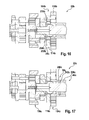
- FIG. 16 another alternative embodiment of a first Schlagabschaltvorraum 24b is shown schematically.
- a planet carrier 114b of a first planetary gear stage 104b is formed in two parts.
- a first part 232b of the planet carrier 114b carries planet wheels 112b of the first planetary gear stage 104b.
- a second part 234b of the planet carrier 114b is rotationally coupled to a second planetary gear stage 106b.
- a first impact shut-off device 24b of a percussion mechanism 22b has a freewheel 236b which appears appropriate to a person skilled in the art and non-rotatably connects the first part 232b and the second part 234b of the planet carrier 114b in a clockwise rotational drilling direction and separates them in a left-handed rotary drilling direction.
- a ring gear 116b of the first planetary gear stage 104b is permanently connected in a rotationally fixed manner to a hand tool housing.
- a next embodiment of a first impact shut-off device 24c is shown schematically.
- a percussion spindle 46c of a percussion mechanism 22c is formed in two parts.
- a first part 238c of the percussion spindle 46c is connected to a racket driving device.
- a second part 240c of the percussion spindle 46c is connected to a second planetary gear stage 106c.
- the first impact shut-off device 24c has one that appears appropriate to the person skilled in the art
- Freewheel 242c rotatably connects the first part 238b and the second part 240c of the percussion spindle 46c at a right-handed Bohrrotationscardi and separates in a left-handed Bohrrotationscardi.
- a ring gear 116c of the first planetary gear stage 104c is permanently connected in a rotationally fixed manner to a hand tool housing.
- FIG. 18 is another embodiment of a shock switch spring 148d shown.
- a second planetary gear stage 106d supports the impact switching spring 148d on a side facing a tool chuck.
- a drive unit 30d supports the impact switching spring 148d on a side facing away from a tool chuck.
- the second planetary gear stage 106d, a third planetary gear stage 108d and a fourth planetary gear stage 110d respectively enclose the striking switching spring 148d on at least one plane aligned perpendicular to an axial direction of the planetary gear stages 106d, 108d, 110d.
- the drive unit 30d is non-rotatably connected to a part of the planetary gear stage 110d.
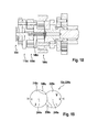
- FIG. 19 shows an alternative embodiment of the operating device 32e and a protection device 226e.
- the operating device 32e has a first operating element 218e and a second operating element 220e.
- the operating elements 218e, 220e are pivotally mounted about axes of rotation 244e, 246e.
- the operating elements 218e, 220e have a disk-shaped basic shape.
- the first control element 218e is, not shown in more detail, connected to a planetary gear mechanism via a mechanism that appears appropriate to a person skilled in the art.
- a first ratio and a second ratio are adjustable.
- the second control element 220e is, not shown in more detail, connected to a control via a mechanism which appears appropriate to a person skilled in the art.
- a screwing mode, a drilling mode and a percussion drilling mode are adjustable.
- a chisel mode could be adjustable.
- the protection device 226e has a free-wheeling area 248e limited by the first operating element 218e.
- the protection device 226e has a freewheeling area 250e limited by the second operating element 220e.
- the freewheeling portion 248e of the first operating member 218e allows adjustment of the tightening mode, the drilling mode and the percussion drilling mode when a second ratio is set.
- the freewheeling area 250e of the second operating member 220e allows adjustment of the tightening mode and the drilling mode when a first gear ratio is adjusted.
- the protector 226e prevents adjustment of the first gear ratio. With the first gear set, the protector 226e prevents adjustment of the percussion drilling mode.
Abstract
Description
Es ist bereits eine Handwerkzeugvorrichtung mit zumindest einer Bedienvorrichtung, über die zumindest eine erste Übersetzung und eine zweite Übersetzung und ein Schlagbohrmodus einstellbar sind, vorgeschlagen worden.It has already been proposed a hand tool device with at least one operating device, via which at least a first ratio and a second ratio and a Schlagbohrmodus are adjustable.
Die Erfindung geht aus von einer Handwerkzeugvorrichtung mit zumindest einer Bedienvorrichtung, über die zumindest eine erste Übersetzung und eine zweite Übersetzung und ein Schlagbohrmodus einstellbar sind.The invention relates to a hand tool device with at least one operating device, via which at least a first ratio and a second ratio and a percussion drilling mode are adjustable.
Es wird vorgeschlagen, dass die Handwerkzeugvorrichtung eine Schutzvorrichtung aufweist, die in dem Schlagbohrmodus einen Betrieb in der ersten Übersetzung verhindert. Unter einer "Bedienvorrichtung" soll in diesem Zusammenhang insbesondere eine Vorrichtung verstanden werden, über die von einem Bediener ein Betriebsmodus zumindest eines Schlagwerks der Handwerkzeugvorrichtung und eine Übersetzung insbesondere eines Planetengetriebes der Handwerkzeugvorrichtung einstellbar sind. Vorzugsweise ist die Bedienvorrichtung dazu vorgesehen, dem Bediener einen aktuell eingestellten Betriebszustand darzustellen, und zwar vorteilhaft durch eine Anordnung von zumindest einem Bedienelement der Bedienvorrichtung. Unter "vorgesehen" soll insbesondere speziell ausgelegt und/oder ausgestattet verstanden werden. Insbesondere soll unter einer "Schutzvorrichtung" eine Vorrichtung verstanden werden, die den Bediener bei einem Arbeitsvorgang schützt. Vorzugsweise ist die Schutzvorrichtung dazu vorgesehen, den Bediener, insbesondere bei einem Blockierfall in dem Schlagbohrmodus, durch eine Begrenzung eines maximalen Werkzeugdrehmoments zu schützen. Unter einem "Werkzeugdrehmoment" soll insbesondere ein von dem Werkzeugfutter insbesondere auf ein Einsatzwerkzeug bewirktes Drehmoment verstanden werden. Unter einem "maximalen Werkzeugdrehmoment" soll insbesondere ein Werkzeugdrehmoment verstanden werden, das in einem Betriebsmodus bei einem weichen Blockierfall auftritt. Vorzugsweise ist das maximale Werkzeugdrehmoment nach der Norm DIN EN 60745 zu bestimmen. Bei einem weichen Blockierfall wird das Werkzeugfutter von dem Einsatzwerkzeug langsam und gleichmäßig, insbesondere innerhalb von zwei Umdrehungen des Werkzeugfutters, abgebremst. Unter einer "Übersetzung" soll insbesondere ein Betriebsmodus verstanden werden, dem ein Verhältnis zwischen einer Drehzahl eines Rotors einer Antriebseinheit der Handwerkzeugvorrichtung und einem Werkzeugfutter der Handwerkzeugvorrichtung zugeordnet ist. Vorzugsweise weist die erste Übersetzung eine geringe maximale Drehzahl und ein großes maximales Werkzeugdrehmoment auf, das heißt insbesondere ein Werkzeugdrehmoment größer als 15 Nm. Vorzugsweise umfasst die zweite Übersetzung eine große maximale Drehzahl und ein geringes maximales Werkzeugdrehmoment, das heißt insbesondere ein Werkzeugdrehmoment kleiner als 15 Nm. Insbesondere soll unter einem "Schlagbohrmodus" ein Betriebsmodus der Handwerkzeugvorrichtung verstanden werden, bei der das Werkzeugfutter und insbesondere ein Schlagwerk der Handwerkzeugvorrichtung das Einsatzwerkzeug drehend und schlagend antreiben. Unter dem Begriff "einstellbar" soll insbesondere verstanden werden, dass der Bediener mittels der Bedienvorrichtung die Handwerkzeugvorrichtung zumindest in die erste Übersetzung, in die zweite Übersetzung und/oder in den Schlagbohrmodus versetzen kann. Vorzugsweise sind über die Bedienvorrichtung zudem zumindest ein Schraubmodus und ein Bohrmodus einstellbar. Des Weiteren könnten über die Bedienvorrichtung eine weitere Übersetzung und ein Meißelmodus einstellbar sein. Unter einem "Schraubmodus" soll insbesondere ein Betriebsmodus der Handwerkzeugvorrichtung verstanden werden, bei dem das Werkzeugfutter das Einsatzwerkzeug bis zum Erreichen eines einstellbaren maximalen Werkzeugdrehmoments drehend antreibt, und zwar insbesondere ohne eine Schlagbewegung. Unter einem "Bohrmodus" soll insbesondere ein Betriebsmodus der Handwerkzeugvorrichtung verstanden werden, bei dem das Werkzeugfutter das Einsatzwerkzeug bis zu einem von einem von der Antriebseinheit abhängigen maximalen Werkzeugdrehmoment drehend eintreibt, und zwar insbesondere ohne eine Schlagbewegung. Unter einem "Meißelmodus" soll insbesondere ein Betriebsmodus der Handwerkzeugvorrichtung verstanden werden, bei dem das Einsatzwerkzeug nur schlagend angetrieben wird. Insbesondere soll unter einem "Betrieb in der ersten Übersetzung" ein Betriebszustand verstanden werden, bei der die erste Übersetzung eingestellt ist. Unter dem Begriff "verhindern" soll in diesem Zusammenhang insbesondere verstanden werden, dass die Schutzvorrichtung einen gleichzeitigen Betrieb in der ersten Übersetzung und in dem Schlagbohrmodus ausschließt. Durch die erfindungsgemäße Ausgestaltung der Handwerkzeugvorrichtung ist konstruktiv einfach ein besonders sicherer Schlagbohrbetrieb möglich.It is proposed that the hand tool device has a protective device which prevents operation in the first gear ratio in the impact drilling mode. In this context, a "control device" should be understood to mean, in particular, a device by means of which an operating mode of at least one percussion mechanism of the hand tool device and a transmission, in particular of a planetary gear, of the hand tool device can be adjusted. Preferably, the operating device is provided to present the operator with a currently set operating state, advantageously by an arrangement of at least one operating element of the operating device. By "intended" is intended to be understood in particular specially designed and / or equipped. In particular, a "protection device" is to be understood as a device which protects the operator during a work process. Preferably, the protective device is provided to the operator, in particular in a blocking case in the Schlagbohrmodus, by limiting a maximum tool torque protect. A "tool torque" should in particular be understood to mean a torque produced by the tool chuck, in particular on an insert tool. A "maximum tool torque" is to be understood in particular a tool torque that occurs in an operating mode in a soft case of blocking. Preferably, the maximum tool torque according to the standard DIN EN 60745 is to be determined. In a soft blocking case, the tool chuck is braked by the insert tool slowly and evenly, in particular within two revolutions of the tool chuck. A "translation" is to be understood in particular as an operating mode to which a ratio between a rotational speed of a rotor of a drive unit of the hand tool device and a tool chuck of the hand tool device is assigned. Preferably, the first ratio has a low maximum speed and a large maximum tool torque, that is, in particular a tool torque greater than 15 Nm. Preferably, the second ratio includes a large maximum speed and a low maximum tool torque, that is, in particular, a tool torque smaller than 15 Nm. In particular, a "hammering mode" is to be understood as an operating mode of the hand tool device in which the tool chuck and in particular a percussion mechanism of the hand tool device drive the insert tool in a rotating and striking manner. The term "adjustable" is to be understood in particular that the operator by means of the operating device can put the hand tool device at least in the first translation, in the second translation and / or in the Schlagbohrmodus. Preferably, at least one screwing mode and a drilling mode can be set via the operating device. Furthermore, another translation and a chisel mode could be adjustable via the operating device. A "screwing mode" is to be understood in particular as an operating mode of the hand tool device in which the tool chuck rotationally drives the insert tool until an adjustable maximum tool torque is reached, in particular without a striking movement. A "drilling mode" is to be understood in particular as an operating mode of the hand tool device in which the tool chuck rotationally drives the insert tool up to a maximum tool torque dependent on the drive unit, in particular without a striking movement. A "chisel mode" is to be understood, in particular, as an operating mode of the hand tool device in which the insert tool is driven only by striking. In particular, a "state of operation in the first translation" is to be understood as an operating state in which the first translation is set. The term "prevent" is to be understood in this context in particular that the protective device precludes simultaneous operation in the first translation and in the Schlagbohrmodus. The inventive design of the hand tool device structurally simple, a particularly safe percussion drilling operation is possible.
Des Weiteren wird vorgeschlagen, dass die Schutzvorrichtung, wenn die erste Übersetzung eingestellt ist, ein Umschalten in den Schlagbohrmodus verhindert, wodurch eine besonders einfache, preiswerte und zuverlässige Konstruktion möglich ist. Vorteilhaft verhindert die Schutzvorrichtung ein Einrasten des Bedienelements in eine dem Schlagbohrmodus zugeordnete Stellung, wenn die erste Übersetzung eingestellt ist. Besonders vorteilhaft verhindert die Schutzvorrichtung ein Verschieben eines Bedienelements in eine dem Schlagbohrmodus zugeordnete Stellung, wenn die erste Übersetzung eingestellt ist. Alternativ könnte die Schutzvorrichtung einen Betrieb verhindern, wenn der Schlagbohrmodus und die erste Übersetzung gleichzeitig eingestellt sind, beispielsweise durch ein Öffnen einer mechanischen Kupplung oder insbesondere elektrisches Abschalten der Antriebseinheit.Furthermore, it is proposed that the protection device, when the first translation is set, prevents switching to the Schlagbohrmodus, whereby a particularly simple, inexpensive and reliable construction is possible. Advantageously, the protection device prevents the operating element from engaging in a position assigned to the percussion drilling mode when the first ratio is set. Particularly advantageously, the protective device prevents a displacement of a control element in a Schlagbohrmodus the assigned position when the first translation is set. Alternatively, the protection device could prevent operation when the percussion drilling mode and the first gear ratio are adjusted simultaneously, for example by opening a mechanical clutch or, in particular, electrically shutting off the drive unit.
Weiterhin wird vorgeschlagen, dass die Schutzvorrichtung, wenn der Schlagbohrmodus eingestellt ist, ein Umschalten in die erste Übersetzung verhindert, wodurch eine besonders einfache, preiswerte und zuverlässige Konstruktion erreicht werden kann. Vorteilhaft verhindert die Schutzvorrichtung ein Einrasten des Bedienelements in einer der zweiten Übersetzung zugeordneten Stellung, wenn der Schlagbohrmodus eingestellt ist. Besonders vorteilhaft verhindert die Schutzvorrichtung ein Verschieben eines Bedienelements in eine der ersten Übersetzung zugeordnete Stellung, wenn der Schlagbohrmodus eingestellt ist.Furthermore, it is proposed that the protection device, when the Schlagbohrmodus is set, prevents switching to the first translation, whereby a particularly simple, inexpensive and reliable construction can be achieved. Advantageously, the protective device prevents the operating element from engaging in a position assigned to the second ratio when the impact drilling mode is set. Particularly advantageously, the protective device prevents a displacement of a control element in a position associated with the first translation when the impact drilling mode is set.
Ferner wird vorgeschlagen, dass ein maximales Werkzeugdrehmoment in der ersten Übersetzung mehr als 15 Nm beträgt, wodurch in dem Bohrmodus und dem Schraubmodus ein besonders wirkungsvoller Betrieb möglich ist.Furthermore, it is proposed that a maximum tool torque in the first gear ratio is more than 15 Nm, whereby a particularly effective operation is possible in the drilling mode and the screwing mode.
Zudem wird vorgeschlagen, dass ein maximales Werkzeugdrehmoment in der zweiten Übersetzung weniger als 15 Nm beträgt, wodurch in dem Bohrmodus eine vorteilhaft hohe Drehzahl und in dem Schlagbohrmodus ein besonders sicherer Betreib erreicht werden kann.In addition, it is proposed that a maximum tool torque in the second ratio is less than 15 Nm, whereby in the drilling mode advantageously high speed and in the Schlagbohrmodus a particularly safe operation can be achieved.
Weiterhin wird vorgeschlagen, dass die Bedienvorrichtung ein erstes Bedienelement aufweist, über das die erste Übersetzung und die zweite Übersetzung einstellbar sind, wodurch konstruktiv einfach eine besonders bedienerfreundliche Wahl einer der Übersetzungen möglich ist. Unter einem "Bedienelement" soll insbesondere ein Bauteil verstanden werden, das eine von einer Bedienereingabe abhängige Kenngröße, insbesondere elektrisch und/oder vorteilhaft mechanisch, abgibt. Vorzugsweise ist das Bedienelement als ein, dem Fachmann als sinnvoll erscheinendes Bedienelement ausgebildet, besonders vorteilhaft als ein mechanisch wirkender Schalter.Furthermore, it is proposed that the operating device has a first operating element, via which the first gear ratio and the second gear ratio are adjustable, as a result of which structurally a particularly user-friendly choice of one of the gear ratios is possible. A "control element" is to be understood, in particular, as a component which emits a parameter dependent on an operator input, in particular electrically and / or advantageously mechanically. Preferably, the operating element is designed as a control element that appears appropriate to the person skilled in the art, particularly advantageously as a mechanically acting switch.
In einer vorteilhaften Ausbildung der Erfindung wird vorgeschlagen, dass die Bedienvorrichtung ein zweites Bedienelement aufweist, über das zumindest der Schlagbohrmodus einstellbar ist, wodurch konstruktiv einfach eine Übertragung der Einstellung von den Bedienelementen auf ein Planetengetriebe und ein Schlagwerk der Handwerkzeugvorrichtung möglich ist.In an advantageous embodiment of the invention it is proposed that the operating device has a second operating element, via which at least the percussion drilling mode is adjustable, whereby structurally simple transmission of the setting of the operating elements to a planetary gear and percussion of the hand tool device is possible.
Ferner wird vorgeschlagen, dass die Schutzvorrichtung zumindest teilweise einstückig mit der Bedienvorrichtung ausgebildet ist, wodurch mit einer vorteilhaft einfachen Konstruktion ein besonders sicherer Betrieb möglich ist. Unter "zumindest teilweise einstückig" soll insbesondere stoffschlüssig verbunden, wie beispielsweise durch einen Schweißprozess und/oder Klebeprozess usw., und besonders vorteilhaft angeformt verstanden werden, wie durch die Herstellung aus einem Guss und/oder durch die Herstellung in einem Ein- oder Mehrkomponentenspritzverfahren.It is also proposed that the protective device is at least partially formed integrally with the operating device, whereby a particularly simple operation is possible with a particularly simple construction. By "at least partially in one piece" should in particular be materially connected, such as by a welding process and / or gluing process, etc., and particularly advantageous molded, as understood by the production of a cast and / or by the production in a single or Mehrkomponentenspritzverfahren.
Zudem wird vorgeschlagen, dass die Handwerkzeugvorrichtung eine einstellbare Drehmomentbegrenzungseinheit umfasst, die dazu vorgesehen ist, ein maximales Werkzeugdrehmoment in einem Schraubmodus zu begrenzen, wodurch ein besonders komfortabler Betrieb im dem Schraubmodus erreicht werden kann. Vorzugsweise sind die Drehmomentbegrenzungseinheit und die Schutzvorrichtung voreinander getrennt ausgebildet. Insbesondere soll unter einer "Drehmomentbegrenzungseinheit" eine Einheit verstanden werden, die dazu vorgesehen ist, ein auf ein Werkstück, insbesondere auf eine Schraube, wirkendes maximales Werkzeugdrehmoment zu begrenzen. Unter "einstellbar" soll in diesem Zusammenhang insbesondere verstanden werden, dass ein maximales Werkzeugdrehmoment von einem Bediener in zumindest drei Stufen, vorteilhaft zumindest fünf Stufen, wählbar ist.In addition, it is proposed that the hand tool device comprises an adjustable torque limiting unit, which is intended to limit a maximum tool torque in a screwing mode, whereby a particularly comfortable operation in the screwing mode can be achieved. Preferably, the torque limiting unit and the protection device are formed separately from each other. In particular, a "torque limiting unit" should be understood to mean a unit which is intended to limit a maximum tool torque acting on a workpiece, in particular on a screw. In this context, "adjustable" is to be understood in particular as meaning that a maximum tool torque can be selected by an operator in at least three stages, advantageously at least five stages.
Weiterhin wird vorgeschlagen, dass die Bedienvorrichtung dazu vorgesehen ist, die Drehmomentbegrenzungseinheit in einen Bohrmodus zu deaktivieren, wodurch vorteilhaft hohe Werkzeugdrehmoment für einen Bohrbetrieb, insbesondere mit Bohrern, die einen großen Durchmesser aufweisen, bereitgestellt werden können. Insbesondere soll unter "deaktivieren" in diesem Zusammenhang verstanden werden, dass die Bedienvorrichtung ein Wirken der Drehmomentbegrenzungseinheit in dem Bohrmodus verhindert, wodurch ein maximales Werkzeugdrehmoment von einem Drehmoment der Antriebseinheit und der gewählten Übersetzung abhängig sind.Furthermore, it is proposed that the operating device is provided to deactivate the torque limiting unit in a drilling mode, whereby advantageously high tool torque for a drilling operation, in particular with drills having a large diameter, can be provided. In particular, "deactivate" in this context is understood to mean that the operating device prevents the torque limiting unit from acting in the drilling mode, whereby a maximum tool torque is dependent on a torque of the drive unit and the selected gear ratio.
Des Weiteren geht die Erfindung aus von einem Handwerkzeug mit einer erfindungsgemäßen Handwerkzeugvorrichtung. Vorzugsweise ist das Handwerkzeug dazu vorgesehen, das Einsatzwerkzeug in einem Schraubmodus, in einem Bohrmodus, in einem Schraubbohrmodus und insbesondere in einem Meißelmodus anzutreiben.Furthermore, the invention is based on a hand tool with a hand tool device according to the invention. Preferably, the hand tool is intended to drive the insert tool in a screwing mode, in a drilling mode, in a screwdriving mode, and in particular in a chisel mode.
Weitere Vorteile ergeben sich aus der folgenden Zeichnungsbeschreibung. In der Zeichnung sind fünf Ausführungsbeispiele der Erfindung dargestellt. Die Zeichnung, die Beschreibung und die Ansprüche enthalten zahlreiche Merkmale in Kombination. Der Fachmann wird die Merkmale zweckmäßigerweise auch einzeln betrachten und zu sinnvollen weiteren Kombinationen zusammenfassen.Further advantages emerge from the following description of the drawing. In the drawing, five embodiments of the invention are shown. The drawing, the description and the claims contain numerous features in combination. The person skilled in the art will expediently also consider the features individually and combine them into meaningful further combinations.
Es zeigen:
- Fig. 1
- einen Schnitt eines Handwerkzeugs mit einer erfindungsgemäßen Handwerkzeugvorrichtung,
- Fig. 2
- einen teilweise freigestellten Schnitt durch ein Schlagwerk und ein Planetengetriebe der Handwerkzeugvorrichtung aus
Figur 1 - Fig. 3
- eine erste Schnittfläche A des Schlagwerks der Handwerkzeugvorrichtung aus
Figur 1 - Fig. 4
- eine zweite Schnittfläche B des Schlagwerks der Handwerkzeugvorrichtung aus
Figur 1 - Fig. 5
- eine perspektivische Darstellung einer Schlagwerkspindel des Schlagwerks der Handwerkzeugvorrichtung aus
Figur 1 - Fig. 6
- eine perspektivische Darstellung eines Schlägers des Schlagwerks der Handwerkzeugvorrichtung aus
Figur 1 , - Fig. 7
- eine Schnittfläche C einer ersten Planetengetriebestufe und einer ersten Schlagabschaltvorrichtung der Handwerkzeugvorrichtung aus
Figur 1 , - Fig. 8
- eine Schnittfläche D eines Steuerelements und einer zweiten Schlagabschaltvorrichtung der Handwerkzeugvorrichtung aus
Figur 1 , - Fig. 9
- eine perspektivische Schnittdarstellung eines Teils der Handwerkzeugvorrichtung aus
Figur 1 , - Fig. 10
- eine Schnittfläche E einer Spindelblockiervorrichtung der Handwerkzeugvorrichtung aus
Figur 1 , - Fig. 11
- eine Schnittfläche F durch Blockiermittel der Spindelblockiervorrichtung der Handwerkzeugvorrichtung aus
Figur 1 , - Fig. 12
- eine Schnittfläche G einer zweiten Planetengetriebestufe der Handwerkzeugvorrichtung aus
Figur 1 , - Fig. 13
- eine Schnittfläche H einer dritten Planetengetriebestufe der Handwerkzeugvorrichtung aus
Figur 1 , - Fig. 14
eine Schnittfläche 1 einer vierten Planetengetriebestufe der Handwerkzeugvorrichtung ausFigur 1 ,- Fig. 15
- eine schematische Darstellung einer Bedienvorrichtung und einer Schutzvorrichtung der Handwerkzeugvorrichtung aus
Figur 1 , - Fig. 16
- ein alternatives Ausführungsbeispiel einer ersten Schlagabschaltvorrichtung einer erfindungsgemäßen Handwerkzeugvorrichtung,
- Fig. 17
- ein weiteres Ausführungsbeispiel einer ersten Schlagabschaltvorrichtung einer erfindungsgemäßen Handwerkzeugvorrichtung,
- Fig. 18
- ein alternatives Ausführungsbeispiel einer Schlagschaltfeder einer erfindungsgemäßen Handwerkzeugvorrichtung und
- Fig. 19
- ein alternatives Ausführungsbeispiel einer Bedienvorrichtung und einer Schutzvorrichtung einer erfindungsgemäßen Handwerkzeugvorrichtung.
- Fig. 1
- a section of a hand tool with a hand tool device according to the invention,
- Fig. 2
- a partially cutaway section through a striking mechanism and a planetary gear of the hand tool device
FIG. 1 . - Fig. 3
- a first sectional area A of the striking mechanism of the hand tool device
FIG. 1 . - Fig. 4
- a second cut surface B of the striking mechanism of the hand tool device
FIG. 1 . - Fig. 5
- a perspective view of a percussion spindle of the percussion of the hand tool device
FIG. 1 . - Fig. 6
- a perspective view of a racket of the striking mechanism of the hand tool device
FIG. 1 . - Fig. 7
- a sectional area C of a first planetary gear stage and a first Schlagabschaltvorrichtung the hand tool device from
FIG. 1 . - Fig. 8
- a sectional area D of a control and a second Schlagabschaltvorrichtung the hand tool device from
FIG. 1 . - Fig. 9
- a perspective sectional view of a part of the hand tool device
FIG. 1 . - Fig. 10
- a sectional surface E of a spindle locking device of the hand tool device
FIG. 1 . - Fig. 11
- a sectional area F by blocking means of the spindle locking device of the hand tool device
FIG. 1 . - Fig. 12
- a sectional area G of a second planetary gear stage of the hand tool device
FIG. 1 . - Fig. 13
- a sectional area H of a third planetary gear stage of the hand tool device
FIG. 1 . - Fig. 14
- a
sectional area 1 of a fourth planetary gear stage of the hand tool deviceFIG. 1 . - Fig. 15
- a schematic representation of an operating device and a protective device of the hand tool device
FIG. 1 . - Fig. 16
- an alternative embodiment of a first Schlagabschaltvorrichtung a hand tool device according to the invention,
- Fig. 17
- a further embodiment of a first Schlagabschaltvorrichtung a hand tool device according to the invention,
- Fig. 18
- an alternative embodiment of a striking spring of a hand tool device according to the invention and
- Fig. 19
- an alternative embodiment of an operating device and a protective device of a hand tool device according to the invention.
Die Werkzeugführungseinheit 20a umfasst ein Werkzeugfutter 36a und eine Werkzeugspindel 38a. Das Werkzeugfutter 36a befestigt bei einem Arbeitsvorgang ein hier nicht dargestelltes Einsatzwerkzeug, beispielsweise einen Bohrer bzw. ein Schraubbit. Das Werkzeugfutter 36a befestigt das Einsatzwerkzeug kraftschlüssig. Das Werkzeugfutter 36a weist drei von einem Bediener bewegbar befestigte Spannbacken auf, die bei einem Arbeitsvorgang das Einsatzwerkzeug befestigen. Zudem befestigt das Werkzeugfutter 36a das Einsatzwerkzeug bei einem Arbeitsvorgang axial unbeweglich gegenüber dem Werkzeugfutter 36a und insbesondere der Werkzeugspindel 38a. Ein Teil des Werkzeugfutters 36a und die Werkzeugspindel 38a sind relativ zueinander unbeweglich miteinander verbunden. Hier sind das Werkzeugfutter 36a und die Werkzeugspindel 38a miteinander verschraubt. Die Handwerkzeugvorrichtung 12a weist ein Lagermittel 40a auf, das die Werkzeugspindel 38a auf einer dem Werkzeugfutter 36a zugewandten Seite lagert. Das Lagermittel 40a lagert die Werkzeugspindel 38a axial verschiebbar. Das Lagermittel 40a ist axial fest mit der Werkzeugspindel 38a verbunden. Das Lagermittel 40a ist axial bewegbar in dem Handwerkzeuggehäuse 14a gelagert. Die Handwerkzeugvorrichtung 12a weist ein weiteres Lagermittel 41a auf, das die Werkzeugspindel 38a auf einer dem Planetengetriebe 28a zugewandten Seite lagert. Das Lagermittel 41 a ist als ein Wälzlager, hier als ein Nadellager, ausgebildet, wodurch eine spielarme Lagerung möglich ist. Das Lagermittel 41 a lagert die Werkzeugspindel 38a axial verschiebbar. Einer Schlagwerkspindel 46a umschließt das Lagermittel 41 a. Das Lagermittel 41 a ist wirkungsmäßig zwischen der Werkzeugspindel 38a und der Schlagwerkspindel 46a angeordnet.The
Die Werkzeugspindel 38a umfasst eine Schlagfläche 42a, auf die bei einem Schlagbohrbetrieb ein Schläger 44a des Schlagwerks 22a schlägt. Der Schläger 44a weist eine Masse auf, die maximal zwei Drittel so groß ist wie eine Masse der Werkzeugführungseinheit 20a. Hier ist die Masse des Schlägers 44a weniger als halb so groß wie die Masse der Werkzeugführungseinheit 20a. Die Masse des Schlägers 44a beträgt etwa 45 % der Masse der Werkzeugführungseinheit 20a.The
In der
Die
Die Schlagwerkfeder 48a beschleunigt den Schläger 44a vor einem Schlag in Schlagrichtung 54a. Dazu stützt das Handwerkzeuggehäuse 14a die Schlagwerkfeder 48a auf einer dem Schläger 44a abgewandten Seite ab. Die Schlagwerkfeder 48a drückt direkt gegen den Schläger 44a. Der Schläger 44a weist eine Federbefestigung 60a auf. Die Federbefestigung 60a ist als eine ringförmige Vertiefung ausgebildet.
Die Schlagwerkspindel 46a ist als eine Hohlwelle ausgebildet. Das Planetengetriebe 28a treibt die Schlagwerkspindel 46a an. Dazu weist die Schlagwerkspindel 46a auf einer dem Werkzeugfutter 36a abgewandten Seite eine Verzahnung 76a auf. Die Führungskurven 66a, 68a weisen jeweils einen Schlagfreilaufbereich 78a, 80a, einen Schlagaufzugsbereich 82a, 84a und eine Montageaussparung 86a, 88a auf. Bei einer Montage werden die Verbindungsmittel 70a, 72a durch die Montageaussparungen 86a, 88a in die Befestigungsaussparungen 74a des Schlägers 44a eingebracht. Die Schlagwerkspindel 46a rotiert bei dem Schlagbohrbetrieb in Schlagrichtung 54a gesehen im Uhrzeigersinn. Die Schlagaufzugsbereiche 82a, 84a sind spiralförmig ausgebildet. Sie erstrecken sich um 180 Grad um eine Rotationsachse 90a der Schlagwerkspindel 46a. Die Schlagaufzugsbereiche 82a, 84a bewegen die Verbindungsmittel 70a, 72a und damit den Schläger 44a bei dem Schlagbohrbetrieb entgegen der Schlagrichtung 54a. Somit weist das Schlagwerk 22a die Verbindungsmittel 70a, 72a auf, welche in zumindest einem Betriebszustand eine Bewegung von der Schlagwerkspindel 46a auf den Schläger 44a übertragen.The
Die Schlagfreilaufbereiche 78a, 80a verbinden je zwei Enden 92a, 94a, 96a, 98a der Schlagaufzugsbereiche 82a, 84a. Die Schlagfreilaufbereiche 78a, 80a erstrecken sich um 180 Grad um eine Rotationsachse 90a der Schlagwerkspindel 46a. Die Schlagfreilaufbereiche 78a, 80a weisen je eine Schlagflanke 100a, 102a auf, die, von einem dem Planetengetriebe 28a zugewandten Ende 94a, 96a des Schlagaufzugsbereichs 82a ausgehend, in etwa parallel zu der Schlagrichtung 54a verläuft. Nachdem die Verbindungsmittel 70a, 72a in die Schlagfreilaufbereiche 78a, 80a eindringen, beschleunigt die Schlagwerkfeder 48a den Schläger 44a und die Verbindungsmittel 70a, 72a in Schlagrichtung 54a. Dabei bewegen sich die Verbindungsmittel 70a, 72a durch die Schlagfreilaufbereiche 78a, 80a, ohne eine axiale Kraft zu erfahren, bis der Schläger 44a auf die Schlagfläche 42a trifft. Die Kurvenführungen 62a, 64a sind um 180 Grad um die Rotationsachse 90a versetzt angeordnet. Die Kurvenführungen 62a, 64a sind in axialer Richtung hintereinander angeordnet.The hammer-
Das Planetengetriebe 28a weist die erste Planetengetriebestufe 104a, eine zweite Planetengetriebestufe 106a, eine dritte Planetengetriebestufe 108a und eine vierte Planetengetriebestufe 110a auf.
Die erste Schlagabschaltvorrichtung 24a fixiert bei einem Schlagbohrbetrieb das Hohlrad 116a der ersten Planetengetriebestufe 104a relativ zu dem Handwerkzeuggehäuse 14a unbeweglich. Die erste Schlagabschaltvorrichtung 24a ist dazu vorgesehen, die Schlägerantriebsvorrichtung 50a bei einer ersten, rechtslaufenden Bohrrotationsrichtung einzuschalten und die Schlägerantriebsvorrichtung 50a bei einer zweiten, linkslaufenden Bohrrotationsrichtung selbstständig abzuschalten. Die erste Schlagabschaltvorrichtung 24a wirkt auf das Hohlrad 116a der ersten Planetengetriebestufe 104a. Die erste Schlagabschaltvorrichtung 24a blockiert das Hohlrad 116a der ersten Planetengetriebestufe 104a bei der ersten, rechtslaufenden Bohrrotationsrichtung. Die erste Schlagabschaltvorrichtung 24a gibt das Hohlrad 116a der ersten Planetengetriebestufe 104a bei der zweiten, linkslaufenden Bohrrotationsrichtung frei, so dass es sich drehen kann. Dazu weist die erste Schlagabschaltvorrichtung 24a drei Klemmmechanismen 122a auf. Die Klemmmechanismen 122a umfassen jeweils ein Blockiermittel 124a, eine erste Klemmfläche 126a, eine zweite Klemmfläche 128a und Freilaufflächen 130a. Das Blockiermittel 124a ist als eine Walze ausgebildet. Die erste Klemmfläche 126a bildet einen außenliegenden Bereich einer Oberfläche des Hohlrads 116a der ersten Planetengetriebestufe 104a. Die zweite Klemmfläche 128a ist relativ zu dem Handwerkzeuggehäuse 14a unbeweglich angeordnet. Bei einem Betrieb in der ersten, rechtslaufenden Bohrrotationsrichtung klemmen die Blockiermittel 124a zwischen den ersten Klemmflächen 126a und der zweiten Klemmfläche 128a. Bei einem Betrieb in der zweiten, linkslaufenden Bohrrotationsrichtung führen die Freilaufflächen 130a die Blockiermittel 124a und verhindern ein Verklemmen.The
Des Weiteren zeigt die
Ferner zeigen die
Die zweite Schlagabschaltvorrichtung 26a weist eine Schlagabschaltkupplung 142a auf. Die Schlagabschaltkupplung 142a ist teilweise einstückig mit dem Planetengetriebe 28a ausgebildet. Die Schlagabschaltkupplung 142a ist zwischen der ersten Planetengetriebestufe 104a und der zweiten Planetengetriebestufe 106a angeordnet. Die Schlagabschaltkupplung 142a weist ein erstes Kupplungselement 144a auf, das drehfest mit einem Planetenträger 114a der ersten Planetengetriebestufe 104a verbunden ist. Die Schlagabschaltkupplung 142a weist ein zweites Kupplungselement 146a auf, das drehfest mit einem Planetenträger 120a der zweiten Planetengetriebestufe 106a verbunden ist. In dem dargestellten Schraubmodus und dem Bohrmodus ist die Schlagabschaltkupplung 142a geöffnet. Bei einem Schlagbohrvorgang überträgt die Werkzeugspindel 38a eine axiale Kupplungskraft auf die Schlagabschaltkupplung 142a, wenn der Bediener ein Einsatzwerkzeug gegen ein Werkstück drückt. Die Kupplungskraft schließt die Schlagabschaltkupplung 142a. In der
Der Planetenträger 120a der zweiten Planetengetriebestufe 106a ist zweiteilig ausgebildet. Ein erstes Teil 150a des Planetenträgers 120a der zweiten Planetengetriebestufe 106a ist drehfest mit der Werkzeugspindel 38a verbunden. Das erste Teil 150a des Planetenträgers 120a ist axial verschiebbar mit der Werkzeugspindel 38a verbunden, wodurch der Planetenträgers 120a auch bei einem Schlag mit der Werkzeugspindel 38a drehgekoppelt bleibt. Somit ist das erste Teil 150a permanent mit der Werkzeugspindel 38a verbunden. Das erste Teil 150a des Planetenträgers 120a ist gegen die Schlagschaltfeder 148a axial verschiebbar gelagert. Ein zweites Teil 152a des Planetenträgers 120a der zweiten Planetengetriebestufe 106a ist drehfest mit dem ersten Teil 150a des Planetenträgers 120a verbunden. Das erste Teil 150a und das zweite Teil 152a des Planetenträgers 120a sind zueinander axial verschiebbar verbunden. Das erste Teil 150a und das zweite Teil 152a des Planetenträgers 120a sind permanent drehfest verbunden.The
Die
Das Steuerelement 134a der Handwerkzeugvorrichtung 12a weist Abstützmittel 190a auf, die zumindest bei einem Bohrbetrieb eine axiale Bewegung des Anschlagsmittel 182a verhindern. Dazu stützen die Abstützmittel 190a das Anschlagsmittel 182a in axialer Richtung ab. Das Anschlagsmittel 182a weist Schraubaussparungen 192a auf, in die die Anschlagsmittel 182a bei einem insbesondere in der
Das Hohlrad 204a der dritten Planetengetriebestufe 108a ist wie in
Die Bedienvorrichtung 32a weist ein erstes Bedienelement 218a und ein zweites Bedienelement 220a auf. Das erste Bedienelement 218a ist auf einer dem Handgriff 18a abgewandten Seite des Handwerkzeuggehäuses 14a angeordnet. Es ist parallel zur axialen Richtung des Planetengetriebes 28a bewegbar gelagert. Das erstes Bedienelement 218a ist über ein Verstellmittel 222a der Bedienvorrichtung 32a in axialer Richtung mit dem Hohlrad 204a der dritten Planetengetriebestufe 108a verbunden. Das Hohlrad 204a der dritten Planetengetriebestufe 108a weist eine Nut 224a auf, in die das Verstellmittel 222a eingreift. Somit ist das Hohlrad 204a der dritten Planetengetriebestufe 108a mit dem Verstellmittel 222a, relativ zu dem Verstellmittel 222a axial drehbar, in axialer Richtung verbunden. Das Verstellmittel 222a ist federnd ausgebildet, wodurch die Übersetzung von einer Drehstellung des Hohlrad 204a der dritten Planetengetriebestufe 108a unabhängig verstellt werden kann. Wenn das erste Bedienelement 218a in Richtung des Werkzeugfutters 36a geschoben ist, ist die erste Übersetzung eingestellt. Wenn das zweite Bedienelement 220a von dem Werkzeugfutter 36a weggeschoben ist, ist die zweite Übersetzung eingestellt.The operating
Das zweite Bedienelement 220a ist auf einer dem Handgriff 18a abgewandten Seite des Handwerkzeuggehäuses 14a angeordnet. Das zweite Bedienelement 220a ist um eine Achse verschiebbar angeordnet, die parallel zu der axialen Richtung des Planetengetriebes 28a ausgerichtet ist. Das zweite Bedienelement 220a ist drehfest mit dem Steuerelement 134a der Handwerkzeugvorrichtung 12a verbunden. Mittels des zweiten Bedienelements 220a sind der Schraubmodus, der Bohrmodus und der Schlagbohrmodus einstellbar. Wenn das zweite Bedienelement 220a in Schlagrichtung 54a gesehen nach links geschoben ist, ist der Schlagbohrmodus eingestellt. Wenn das zweite Bedienelement 220a in Schlagrichtung 54a gesehen nach rechts geschoben ist, ist der Schraubmodus eingestellt. Wenn das zweite Bedienelement 220a in Schlagrichtung 54a gesehen mittig angeordnet ist, ist der Bohrmodus eingestellt.The
Die Antriebseinheit 30a ist als ein Elektromotor ausgebildet. Die Antriebseinheit 30a weist ein maximales Drehmoment auf, das ein maximales Werkzeugdrehmoment in der ersten Übersetzung von mehr als 15 Nm und in der zweiten Übersetzung von weniger als 15 m verursacht. Das maximale Werkzeugdrehmoment in der ersten Übersetzung beträgt 30 Nm. Das maximale Werkzeugdrehmoment in der zweiten Übersetzung beträgt 10 Nm. Das Werkzeugdrehmoment ist dabei nach der Norm DIN EN 60745 zu bestimmen.The
Die Schlagschaltfeder 148a der Handwerkzeugvorrichtung 12a öffnet bei einem Schlagbohrbetrieb die Schlagabschaltkupplung 142a, wenn der Bediener das Einsatzwerkzeug von dem Werkstück absetzt. Die Schlagschaltfeder 148a ist koaxial zu den Planetengetriebestufen 104a, 106a, 108a, 110a des Planetengetriebes 28a angeordnet. Die zweite Planetengetriebestufe 106a und die dritte Planetengetriebestufe 108a umschließen die Schlagschaltfeder 148a jeweils auf zumindest einer Ebene, die senkrecht zu der axialen Richtung des Planetengetriebes 28a ausgerichtet ist. Die zweite Planetengetriebestufe 106a und die dritte Planetengetriebestufe 108a sind jeweils wirkungsmäßig zwischen zumindest zwei weiteren Planetengetriebestufen 104a, 106a, 108a, 110a des Planetengetriebes 28a angeordnet. Der Planetenträger 120a der zweiten Planetengetriebestufe 106a stützt die Schlagschaltfeder 148a auf einer dem Werkzeugfutter 36a abgewandten Seite ab.The
In den
In der
In der
In der
Die Schutzvorrichtung 226e weist einen von dem ersten Bedienelement 218e begrenzten Freilaufbereich 248e auf. Die Schutzvorrichtung 226e weist einen von dem zweiten Bedienelement 220e begrenzten Freilaufbereich 250e auf. Der Freilaufbereich 248e des ersten Bedienelements 218e ermöglicht ein Einstellen des Schraubmodus, des Bohrmodus und des Schlagbohrmodus, wenn eine zweite Übersetzung eingestellt ist. Der Freilaufbereich 250e des zweiten Bedienelement 220e ermöglicht ein Einstellen des Schraubmodus und des Bohrmodus, wenn eine erste Übersetzung eingestellt ist. In dem Schlagbohrmodus verhindert die Schutzvorrichtung 226e ein Einstellen der ersten Übersetzung. Bei eingestellter erster Übersetzung verhindert die Schutzvorrichtung 226e ein Einstellen des Schlagbohrmodus.The
Claims (11)
Applications Claiming Priority (1)
| Application Number | Priority Date | Filing Date | Title |
|---|---|---|---|
| DE102011089919A DE102011089919A1 (en) | 2011-12-27 | 2011-12-27 | Hand tool device |
Publications (2)
| Publication Number | Publication Date |
|---|---|
| EP2612730A1 true EP2612730A1 (en) | 2013-07-10 |
| EP2612730B1 EP2612730B1 (en) | 2021-09-08 |
Family
ID=47296980
Family Applications (1)
| Application Number | Title | Priority Date | Filing Date |
|---|---|---|---|
| EP12195397.0A Active EP2612730B1 (en) | 2011-12-27 | 2012-12-04 | Handheld tool apparatus |
Country Status (4)
| Country | Link |
|---|---|
| US (1) | US20130161042A1 (en) |
| EP (1) | EP2612730B1 (en) |
| CN (1) | CN103182547A (en) |
| DE (1) | DE102011089919A1 (en) |
Families Citing this family (6)
| Publication number | Priority date | Publication date | Assignee | Title |
|---|---|---|---|---|
| DE102011089921A1 (en) * | 2011-12-27 | 2013-06-27 | Robert Bosch Gmbh | Hand tool device |
| DE102011089917B4 (en) * | 2011-12-27 | 2023-12-07 | Robert Bosch Gmbh | Hand tool device |
| DE102011089913A1 (en) * | 2011-12-27 | 2013-06-27 | Robert Bosch Gmbh | Hand tool device |
| DE102012209446A1 (en) * | 2012-06-05 | 2013-12-05 | Robert Bosch Gmbh | Hand machine tool device |
| CN104837427B (en) | 2012-11-14 | 2017-09-22 | 不列颠哥伦比亚癌症机构分部 | Tubulose hammer drill accessory |
| US10328560B2 (en) * | 2015-02-23 | 2019-06-25 | Brian Romagnoli | Multi-mode drive mechanisms and tools incorporating the same |
Citations (4)
| Publication number | Priority date | Publication date | Assignee | Title |
|---|---|---|---|---|
| DE102006009922A1 (en) * | 2006-03-03 | 2007-09-06 | Robert Bosch Gmbh | Switchable coupling for an electric hand tool |
| EP1857228A1 (en) * | 2006-05-19 | 2007-11-21 | Black & Decker, Inc. | Mode change mechanism for a power tool |
| EP2062697A1 (en) * | 2007-11-21 | 2009-05-27 | Black & Decker, Inc. | Muilti-mode Drill with Mode Collar |
| EP2554306A2 (en) * | 2011-08-05 | 2013-02-06 | Makita Corporation | Electric power tool |
Family Cites Families (5)
| Publication number | Priority date | Publication date | Assignee | Title |
|---|---|---|---|---|
| DE102004018084B3 (en) * | 2004-04-08 | 2005-11-17 | Hilti Ag | hammer drill |
| DE102004051911A1 (en) * | 2004-10-26 | 2006-04-27 | Robert Bosch Gmbh | Hand tool, in particular drill |
| US7308948B2 (en) * | 2004-10-28 | 2007-12-18 | Makita Corporation | Electric power tool |
| US7314097B2 (en) * | 2005-02-24 | 2008-01-01 | Black & Decker Inc. | Hammer drill with a mode changeover mechanism |
| CN103121205B (en) * | 2007-09-06 | 2015-09-02 | 迪美科技控股有限公司 | The mechanical component of electric tool |
-
2011
- 2011-12-27 DE DE102011089919A patent/DE102011089919A1/en not_active Withdrawn
-
2012
- 2012-12-04 EP EP12195397.0A patent/EP2612730B1/en active Active
- 2012-12-26 CN CN2012105724227A patent/CN103182547A/en active Pending
- 2012-12-26 US US13/726,942 patent/US20130161042A1/en not_active Abandoned
Patent Citations (4)
| Publication number | Priority date | Publication date | Assignee | Title |
|---|---|---|---|---|
| DE102006009922A1 (en) * | 2006-03-03 | 2007-09-06 | Robert Bosch Gmbh | Switchable coupling for an electric hand tool |
| EP1857228A1 (en) * | 2006-05-19 | 2007-11-21 | Black & Decker, Inc. | Mode change mechanism for a power tool |
| EP2062697A1 (en) * | 2007-11-21 | 2009-05-27 | Black & Decker, Inc. | Muilti-mode Drill with Mode Collar |
| EP2554306A2 (en) * | 2011-08-05 | 2013-02-06 | Makita Corporation | Electric power tool |
Also Published As
| Publication number | Publication date |
|---|---|
| DE102011089919A1 (en) | 2013-06-27 |
| US20130161042A1 (en) | 2013-06-27 |
| CN103182547A (en) | 2013-07-03 |
| EP2612730B1 (en) | 2021-09-08 |
Similar Documents
| Publication | Publication Date | Title |
|---|---|---|
| DE102011089913A1 (en) | Hand tool device | |
| EP2797721B1 (en) | Hand tool device | |
| EP2612732A1 (en) | Handheld tool apparatus | |
| EP2448715B1 (en) | Hand-held power tool | |
| EP3056317B1 (en) | Handheld machine tool | |
| DE102013208895B4 (en) | Hand tool device | |
| EP2612730B1 (en) | Handheld tool apparatus | |
| EP2803447B1 (en) | Handheld tool apparatus | |
| EP2612731B1 (en) | Handheld tool apparatus | |
| EP2448716B1 (en) | Hand-held power tool | |
| DE102013208900A1 (en) | Hand tool device | |
| DE102011089917B4 (en) | Hand tool device | |
| DE102013208890B4 (en) | Hand tool device | |
| DE102010001683A1 (en) | Hand-held power tool device i.e. drilling hammer device, for use in e.g. drilling machine, has hammer mechanism with operation unit, which is connected with ventilation hole closure unit and holds closure unit in open position | |
| DE102013208902B4 (en) | Hand tool device | |
| EP2646200A1 (en) | Hammer percussion mechanism | |
| DE102014207370A1 (en) | Hand tool device | |
| WO2012072325A1 (en) | Hammer percussion mechanism | |
| EP2212061A1 (en) | Hand-held machine tool |
Legal Events
| Date | Code | Title | Description |
|---|---|---|---|
| PUAI | Public reference made under article 153(3) epc to a published international application that has entered the european phase |
Free format text: ORIGINAL CODE: 0009012 |
|
| AK | Designated contracting states |
Kind code of ref document: A1 Designated state(s): AL AT BE BG CH CY CZ DE DK EE ES FI FR GB GR HR HU IE IS IT LI LT LU LV MC MK MT NL NO PL PT RO RS SE SI SK SM TR |
|
| AX | Request for extension of the european patent |
Extension state: BA ME |
|
| 17P | Request for examination filed |
Effective date: 20140110 |
|
| RBV | Designated contracting states (corrected) |
Designated state(s): AL AT BE BG CH CY CZ DE DK EE ES FI FR GB GR HR HU IE IS IT LI LT LU LV MC MK MT NL NO PL PT RO RS SE SI SK SM TR |
|
| STAA | Information on the status of an ep patent application or granted ep patent |
Free format text: STATUS: EXAMINATION IS IN PROGRESS |
|
| 17Q | First examination report despatched |
Effective date: 20161213 |
|
| REG | Reference to a national code |
Ref country code: DE Ref legal event code: R079 Ref document number: 502012016895 Country of ref document: DE Free format text: PREVIOUS MAIN CLASS: B25D0016000000 Ipc: B25D0011080000 |
|
| RIC1 | Information provided on ipc code assigned before grant |
Ipc: B23Q 5/12 20060101ALI20190703BHEP Ipc: B25D 11/08 20060101AFI20190703BHEP Ipc: B25D 11/02 20060101ALI20190703BHEP Ipc: B25D 16/00 20060101ALI20190703BHEP |
|
| RAP1 | Party data changed (applicant data changed or rights of an application transferred) |
Owner name: ROBERT BOSCH GMBH |
|
| GRAP | Despatch of communication of intention to grant a patent |
Free format text: ORIGINAL CODE: EPIDOSNIGR1 |
|
| STAA | Information on the status of an ep patent application or granted ep patent |
Free format text: STATUS: GRANT OF PATENT IS INTENDED |
|
| INTG | Intention to grant announced |
Effective date: 20201015 |
|
| GRAJ | Information related to disapproval of communication of intention to grant by the applicant or resumption of examination proceedings by the epo deleted |
Free format text: ORIGINAL CODE: EPIDOSDIGR1 |
|
| STAA | Information on the status of an ep patent application or granted ep patent |
Free format text: STATUS: EXAMINATION IS IN PROGRESS |
|
| INTC | Intention to grant announced (deleted) | ||
| GRAP | Despatch of communication of intention to grant a patent |
Free format text: ORIGINAL CODE: EPIDOSNIGR1 |
|
| STAA | Information on the status of an ep patent application or granted ep patent |
Free format text: STATUS: GRANT OF PATENT IS INTENDED |
|
| INTG | Intention to grant announced |
Effective date: 20210412 |
|
| GRAS | Grant fee paid |
Free format text: ORIGINAL CODE: EPIDOSNIGR3 |
|
| GRAA | (expected) grant |
Free format text: ORIGINAL CODE: 0009210 |
|
| STAA | Information on the status of an ep patent application or granted ep patent |
Free format text: STATUS: THE PATENT HAS BEEN GRANTED |
|
| AK | Designated contracting states |
Kind code of ref document: B1 Designated state(s): AL AT BE BG CH CY CZ DE DK EE ES FI FR GB GR HR HU IE IS IT LI LT LU LV MC MK MT NL NO PL PT RO RS SE SI SK SM TR |
|
| REG | Reference to a national code |
Ref country code: GB Ref legal event code: FG4D Free format text: NOT ENGLISH |
|
| REG | Reference to a national code |
Ref country code: AT Ref legal event code: REF Ref document number: 1428160 Country of ref document: AT Kind code of ref document: T Effective date: 20210915 Ref country code: CH Ref legal event code: EP |
|
| REG | Reference to a national code |
Ref country code: IE Ref legal event code: FG4D Free format text: LANGUAGE OF EP DOCUMENT: GERMAN |
|
| REG | Reference to a national code |
Ref country code: DE Ref legal event code: R096 Ref document number: 502012016895 Country of ref document: DE |
|
| REG | Reference to a national code |
Ref country code: LT Ref legal event code: MG9D |
|
| REG | Reference to a national code |
Ref country code: NL Ref legal event code: MP Effective date: 20210908 |
|
| PG25 | Lapsed in a contracting state [announced via postgrant information from national office to epo] |
Ref country code: NO Free format text: LAPSE BECAUSE OF FAILURE TO SUBMIT A TRANSLATION OF THE DESCRIPTION OR TO PAY THE FEE WITHIN THE PRESCRIBED TIME-LIMIT Effective date: 20211208 Ref country code: RS Free format text: LAPSE BECAUSE OF FAILURE TO SUBMIT A TRANSLATION OF THE DESCRIPTION OR TO PAY THE FEE WITHIN THE PRESCRIBED TIME-LIMIT Effective date: 20210908 Ref country code: ES Free format text: LAPSE BECAUSE OF FAILURE TO SUBMIT A TRANSLATION OF THE DESCRIPTION OR TO PAY THE FEE WITHIN THE PRESCRIBED TIME-LIMIT Effective date: 20210908 Ref country code: FI Free format text: LAPSE BECAUSE OF FAILURE TO SUBMIT A TRANSLATION OF THE DESCRIPTION OR TO PAY THE FEE WITHIN THE PRESCRIBED TIME-LIMIT Effective date: 20210908 Ref country code: BG Free format text: LAPSE BECAUSE OF FAILURE TO SUBMIT A TRANSLATION OF THE DESCRIPTION OR TO PAY THE FEE WITHIN THE PRESCRIBED TIME-LIMIT Effective date: 20211208 Ref country code: LT Free format text: LAPSE BECAUSE OF FAILURE TO SUBMIT A TRANSLATION OF THE DESCRIPTION OR TO PAY THE FEE WITHIN THE PRESCRIBED TIME-LIMIT Effective date: 20210908 Ref country code: HR Free format text: LAPSE BECAUSE OF FAILURE TO SUBMIT A TRANSLATION OF THE DESCRIPTION OR TO PAY THE FEE WITHIN THE PRESCRIBED TIME-LIMIT Effective date: 20210908 Ref country code: SE Free format text: LAPSE BECAUSE OF FAILURE TO SUBMIT A TRANSLATION OF THE DESCRIPTION OR TO PAY THE FEE WITHIN THE PRESCRIBED TIME-LIMIT Effective date: 20210908 |
|
| PG25 | Lapsed in a contracting state [announced via postgrant information from national office to epo] |
Ref country code: LV Free format text: LAPSE BECAUSE OF FAILURE TO SUBMIT A TRANSLATION OF THE DESCRIPTION OR TO PAY THE FEE WITHIN THE PRESCRIBED TIME-LIMIT Effective date: 20210908 Ref country code: GR Free format text: LAPSE BECAUSE OF FAILURE TO SUBMIT A TRANSLATION OF THE DESCRIPTION OR TO PAY THE FEE WITHIN THE PRESCRIBED TIME-LIMIT Effective date: 20211209 |
|
| PG25 | Lapsed in a contracting state [announced via postgrant information from national office to epo] |
Ref country code: IS Free format text: LAPSE BECAUSE OF FAILURE TO SUBMIT A TRANSLATION OF THE DESCRIPTION OR TO PAY THE FEE WITHIN THE PRESCRIBED TIME-LIMIT Effective date: 20220108 Ref country code: SM Free format text: LAPSE BECAUSE OF FAILURE TO SUBMIT A TRANSLATION OF THE DESCRIPTION OR TO PAY THE FEE WITHIN THE PRESCRIBED TIME-LIMIT Effective date: 20210908 Ref country code: SK Free format text: LAPSE BECAUSE OF FAILURE TO SUBMIT A TRANSLATION OF THE DESCRIPTION OR TO PAY THE FEE WITHIN THE PRESCRIBED TIME-LIMIT Effective date: 20210908 Ref country code: RO Free format text: LAPSE BECAUSE OF FAILURE TO SUBMIT A TRANSLATION OF THE DESCRIPTION OR TO PAY THE FEE WITHIN THE PRESCRIBED TIME-LIMIT Effective date: 20210908 Ref country code: PT Free format text: LAPSE BECAUSE OF FAILURE TO SUBMIT A TRANSLATION OF THE DESCRIPTION OR TO PAY THE FEE WITHIN THE PRESCRIBED TIME-LIMIT Effective date: 20220110 Ref country code: PL Free format text: LAPSE BECAUSE OF FAILURE TO SUBMIT A TRANSLATION OF THE DESCRIPTION OR TO PAY THE FEE WITHIN THE PRESCRIBED TIME-LIMIT Effective date: 20210908 Ref country code: NL Free format text: LAPSE BECAUSE OF FAILURE TO SUBMIT A TRANSLATION OF THE DESCRIPTION OR TO PAY THE FEE WITHIN THE PRESCRIBED TIME-LIMIT Effective date: 20210908 Ref country code: EE Free format text: LAPSE BECAUSE OF FAILURE TO SUBMIT A TRANSLATION OF THE DESCRIPTION OR TO PAY THE FEE WITHIN THE PRESCRIBED TIME-LIMIT Effective date: 20210908 Ref country code: CZ Free format text: LAPSE BECAUSE OF FAILURE TO SUBMIT A TRANSLATION OF THE DESCRIPTION OR TO PAY THE FEE WITHIN THE PRESCRIBED TIME-LIMIT Effective date: 20210908 Ref country code: AL Free format text: LAPSE BECAUSE OF FAILURE TO SUBMIT A TRANSLATION OF THE DESCRIPTION OR TO PAY THE FEE WITHIN THE PRESCRIBED TIME-LIMIT Effective date: 20210908 |
|
| REG | Reference to a national code |
Ref country code: DE Ref legal event code: R097 Ref document number: 502012016895 Country of ref document: DE |
|
| PLBE | No opposition filed within time limit |
Free format text: ORIGINAL CODE: 0009261 |
|
| STAA | Information on the status of an ep patent application or granted ep patent |
Free format text: STATUS: NO OPPOSITION FILED WITHIN TIME LIMIT |
|
| PG25 | Lapsed in a contracting state [announced via postgrant information from national office to epo] |
Ref country code: MC Free format text: LAPSE BECAUSE OF FAILURE TO SUBMIT A TRANSLATION OF THE DESCRIPTION OR TO PAY THE FEE WITHIN THE PRESCRIBED TIME-LIMIT Effective date: 20210908 Ref country code: DK Free format text: LAPSE BECAUSE OF FAILURE TO SUBMIT A TRANSLATION OF THE DESCRIPTION OR TO PAY THE FEE WITHIN THE PRESCRIBED TIME-LIMIT Effective date: 20210908 |
|
| REG | Reference to a national code |
Ref country code: CH Ref legal event code: PL |
|
| 26N | No opposition filed |
Effective date: 20220609 |
|
| GBPC | Gb: european patent ceased through non-payment of renewal fee |
Effective date: 20211208 |
|
| PG25 | Lapsed in a contracting state [announced via postgrant information from national office to epo] |
Ref country code: SI Free format text: LAPSE BECAUSE OF FAILURE TO SUBMIT A TRANSLATION OF THE DESCRIPTION OR TO PAY THE FEE WITHIN THE PRESCRIBED TIME-LIMIT Effective date: 20210908 |
|
| REG | Reference to a national code |
Ref country code: BE Ref legal event code: MM Effective date: 20211231 |
|
| PG25 | Lapsed in a contracting state [announced via postgrant information from national office to epo] |
Ref country code: LU Free format text: LAPSE BECAUSE OF NON-PAYMENT OF DUE FEES Effective date: 20211204 Ref country code: IE Free format text: LAPSE BECAUSE OF NON-PAYMENT OF DUE FEES Effective date: 20211204 Ref country code: GB Free format text: LAPSE BECAUSE OF NON-PAYMENT OF DUE FEES Effective date: 20211208 |
|
| PG25 | Lapsed in a contracting state [announced via postgrant information from national office to epo] |
Ref country code: BE Free format text: LAPSE BECAUSE OF NON-PAYMENT OF DUE FEES Effective date: 20211231 |
|
| PG25 | Lapsed in a contracting state [announced via postgrant information from national office to epo] |
Ref country code: LI Free format text: LAPSE BECAUSE OF NON-PAYMENT OF DUE FEES Effective date: 20211231 Ref country code: CH Free format text: LAPSE BECAUSE OF NON-PAYMENT OF DUE FEES Effective date: 20211231 |
|
| PG25 | Lapsed in a contracting state [announced via postgrant information from national office to epo] |
Ref country code: IT Free format text: LAPSE BECAUSE OF FAILURE TO SUBMIT A TRANSLATION OF THE DESCRIPTION OR TO PAY THE FEE WITHIN THE PRESCRIBED TIME-LIMIT Effective date: 20210908 |
|
| REG | Reference to a national code |
Ref country code: AT Ref legal event code: MM01 Ref document number: 1428160 Country of ref document: AT Kind code of ref document: T Effective date: 20211204 |
|
| PG25 | Lapsed in a contracting state [announced via postgrant information from national office to epo] |
Ref country code: AT Free format text: LAPSE BECAUSE OF NON-PAYMENT OF DUE FEES Effective date: 20211204 |
|
| PG25 | Lapsed in a contracting state [announced via postgrant information from national office to epo] |
Ref country code: HU Free format text: LAPSE BECAUSE OF FAILURE TO SUBMIT A TRANSLATION OF THE DESCRIPTION OR TO PAY THE FEE WITHIN THE PRESCRIBED TIME-LIMIT; INVALID AB INITIO Effective date: 20121204 Ref country code: CY Free format text: LAPSE BECAUSE OF FAILURE TO SUBMIT A TRANSLATION OF THE DESCRIPTION OR TO PAY THE FEE WITHIN THE PRESCRIBED TIME-LIMIT Effective date: 20210908 |
|
| PGFP | Annual fee paid to national office [announced via postgrant information from national office to epo] |
Ref country code: DE Payment date: 20230223 Year of fee payment: 11 |
|
| PGFP | Annual fee paid to national office [announced via postgrant information from national office to epo] |
Ref country code: FR Payment date: 20231219 Year of fee payment: 12 |
|
| REG | Reference to a national code |
Ref country code: DE Ref legal event code: R084 Ref document number: 502012016895 Country of ref document: DE |