EP2612601A1 - Apparatus and method for realizing synchronization image - Google Patents
Apparatus and method for realizing synchronization image Download PDFInfo
- Publication number
- EP2612601A1 EP2612601A1 EP13150129.8A EP13150129A EP2612601A1 EP 2612601 A1 EP2612601 A1 EP 2612601A1 EP 13150129 A EP13150129 A EP 13150129A EP 2612601 A1 EP2612601 A1 EP 2612601A1
- Authority
- EP
- European Patent Office
- Prior art keywords
- points
- realizing
- image
- synchronization image
- velocity
- Prior art date
- Legal status (The legal status is an assumption and is not a legal conclusion. Google has not performed a legal analysis and makes no representation as to the accuracy of the status listed.)
- Withdrawn
Links
Images



Classifications
-
- A—HUMAN NECESSITIES
- A61—MEDICAL OR VETERINARY SCIENCE; HYGIENE
- A61B—DIAGNOSIS; SURGERY; IDENTIFICATION
- A61B8/00—Diagnosis using ultrasonic, sonic or infrasonic waves
- A61B8/13—Tomography
- A61B8/14—Echotomography
-
- G—PHYSICS
- G01—MEASURING; TESTING
- G01S—RADIO DIRECTION-FINDING; RADIO NAVIGATION; DETERMINING DISTANCE OR VELOCITY BY USE OF RADIO WAVES; LOCATING OR PRESENCE-DETECTING BY USE OF THE REFLECTION OR RERADIATION OF RADIO WAVES; ANALOGOUS ARRANGEMENTS USING OTHER WAVES
- G01S15/00—Systems using the reflection or reradiation of acoustic waves, e.g. sonar systems
- G01S15/02—Systems using the reflection or reradiation of acoustic waves, e.g. sonar systems using reflection of acoustic waves
- G01S15/50—Systems of measurement, based on relative movement of the target
- G01S15/58—Velocity or trajectory determination systems; Sense-of-movement determination systems
- G01S15/62—Sense-of-movement determination
-
- A—HUMAN NECESSITIES
- A61—MEDICAL OR VETERINARY SCIENCE; HYGIENE
- A61B—DIAGNOSIS; SURGERY; IDENTIFICATION
- A61B8/00—Diagnosis using ultrasonic, sonic or infrasonic waves
- A61B8/08—Clinical applications
-
- A—HUMAN NECESSITIES
- A61—MEDICAL OR VETERINARY SCIENCE; HYGIENE
- A61B—DIAGNOSIS; SURGERY; IDENTIFICATION
- A61B8/00—Diagnosis using ultrasonic, sonic or infrasonic waves
- A61B8/48—Diagnostic techniques
- A61B8/488—Diagnostic techniques involving Doppler signals
-
- A—HUMAN NECESSITIES
- A61—MEDICAL OR VETERINARY SCIENCE; HYGIENE
- A61B—DIAGNOSIS; SURGERY; IDENTIFICATION
- A61B8/00—Diagnosis using ultrasonic, sonic or infrasonic waves
- A61B8/52—Devices using data or image processing specially adapted for diagnosis using ultrasonic, sonic or infrasonic waves
- A61B8/5215—Devices using data or image processing specially adapted for diagnosis using ultrasonic, sonic or infrasonic waves involving processing of medical diagnostic data
- A61B8/5223—Devices using data or image processing specially adapted for diagnosis using ultrasonic, sonic or infrasonic waves involving processing of medical diagnostic data for extracting a diagnostic or physiological parameter from medical diagnostic data
-
- G—PHYSICS
- G01—MEASURING; TESTING
- G01S—RADIO DIRECTION-FINDING; RADIO NAVIGATION; DETERMINING DISTANCE OR VELOCITY BY USE OF RADIO WAVES; LOCATING OR PRESENCE-DETECTING BY USE OF THE REFLECTION OR RERADIATION OF RADIO WAVES; ANALOGOUS ARRANGEMENTS USING OTHER WAVES
- G01S15/00—Systems using the reflection or reradiation of acoustic waves, e.g. sonar systems
- G01S15/88—Sonar systems specially adapted for specific applications
- G01S15/89—Sonar systems specially adapted for specific applications for mapping or imaging
- G01S15/8906—Short-range imaging systems; Acoustic microscope systems using pulse-echo techniques
- G01S15/8979—Combined Doppler and pulse-echo imaging systems
- G01S15/8984—Measuring the velocity vector
-
- G—PHYSICS
- G01—MEASURING; TESTING
- G01S—RADIO DIRECTION-FINDING; RADIO NAVIGATION; DETERMINING DISTANCE OR VELOCITY BY USE OF RADIO WAVES; LOCATING OR PRESENCE-DETECTING BY USE OF THE REFLECTION OR RERADIATION OF RADIO WAVES; ANALOGOUS ARRANGEMENTS USING OTHER WAVES
- G01S15/00—Systems using the reflection or reradiation of acoustic waves, e.g. sonar systems
- G01S15/88—Sonar systems specially adapted for specific applications
- G01S15/89—Sonar systems specially adapted for specific applications for mapping or imaging
- G01S15/8906—Short-range imaging systems; Acoustic microscope systems using pulse-echo techniques
- G01S15/8993—Three dimensional imaging systems
-
- G—PHYSICS
- G01—MEASURING; TESTING
- G01S—RADIO DIRECTION-FINDING; RADIO NAVIGATION; DETERMINING DISTANCE OR VELOCITY BY USE OF RADIO WAVES; LOCATING OR PRESENCE-DETECTING BY USE OF THE REFLECTION OR RERADIATION OF RADIO WAVES; ANALOGOUS ARRANGEMENTS USING OTHER WAVES
- G01S7/00—Details of systems according to groups G01S13/00, G01S15/00, G01S17/00
- G01S7/52—Details of systems according to groups G01S13/00, G01S15/00, G01S17/00 of systems according to group G01S15/00
- G01S7/52017—Details of systems according to groups G01S13/00, G01S15/00, G01S17/00 of systems according to group G01S15/00 particularly adapted to short-range imaging
- G01S7/52053—Display arrangements
- G01S7/52057—Cathode ray tube displays
- G01S7/52071—Multicolour displays; using colour coding; Optimising colour or information content in displays, e.g. parametric imaging
-
- G—PHYSICS
- G06—COMPUTING OR CALCULATING; COUNTING
- G06T—IMAGE DATA PROCESSING OR GENERATION, IN GENERAL
- G06T7/00—Image analysis
- G06T7/20—Analysis of motion
-
- G—PHYSICS
- G16—INFORMATION AND COMMUNICATION TECHNOLOGY [ICT] SPECIALLY ADAPTED FOR SPECIFIC APPLICATION FIELDS
- G16H—HEALTHCARE INFORMATICS, i.e. INFORMATION AND COMMUNICATION TECHNOLOGY [ICT] SPECIALLY ADAPTED FOR THE HANDLING OR PROCESSING OF MEDICAL OR HEALTHCARE DATA
- G16H50/00—ICT specially adapted for medical diagnosis, medical simulation or medical data mining; ICT specially adapted for detecting, monitoring or modelling epidemics or pandemics
- G16H50/30—ICT specially adapted for medical diagnosis, medical simulation or medical data mining; ICT specially adapted for detecting, monitoring or modelling epidemics or pandemics for calculating health indices; for individual health risk assessment
-
- A—HUMAN NECESSITIES
- A61—MEDICAL OR VETERINARY SCIENCE; HYGIENE
- A61B—DIAGNOSIS; SURGERY; IDENTIFICATION
- A61B8/00—Diagnosis using ultrasonic, sonic or infrasonic waves
- A61B8/08—Clinical applications
- A61B8/0883—Clinical applications for diagnosis of the heart
-
- A—HUMAN NECESSITIES
- A61—MEDICAL OR VETERINARY SCIENCE; HYGIENE
- A61B—DIAGNOSIS; SURGERY; IDENTIFICATION
- A61B8/00—Diagnosis using ultrasonic, sonic or infrasonic waves
- A61B8/44—Constructional features of the ultrasonic, sonic or infrasonic diagnostic device
- A61B8/4483—Constructional features of the ultrasonic, sonic or infrasonic diagnostic device characterised by features of the ultrasound transducer
-
- A—HUMAN NECESSITIES
- A61—MEDICAL OR VETERINARY SCIENCE; HYGIENE
- A61B—DIAGNOSIS; SURGERY; IDENTIFICATION
- A61B8/00—Diagnosis using ultrasonic, sonic or infrasonic waves
- A61B8/46—Ultrasonic, sonic or infrasonic diagnostic devices with special arrangements for interfacing with the operator or the patient
- A61B8/461—Displaying means of special interest
- A61B8/466—Displaying means of special interest adapted to display 3D data
-
- A—HUMAN NECESSITIES
- A61—MEDICAL OR VETERINARY SCIENCE; HYGIENE
- A61B—DIAGNOSIS; SURGERY; IDENTIFICATION
- A61B8/00—Diagnosis using ultrasonic, sonic or infrasonic waves
- A61B8/48—Diagnostic techniques
- A61B8/483—Diagnostic techniques involving the acquisition of a 3D volume of data
-
- G—PHYSICS
- G01—MEASURING; TESTING
- G01S—RADIO DIRECTION-FINDING; RADIO NAVIGATION; DETERMINING DISTANCE OR VELOCITY BY USE OF RADIO WAVES; LOCATING OR PRESENCE-DETECTING BY USE OF THE REFLECTION OR RERADIATION OF RADIO WAVES; ANALOGOUS ARRANGEMENTS USING OTHER WAVES
- G01S15/00—Systems using the reflection or reradiation of acoustic waves, e.g. sonar systems
- G01S15/88—Sonar systems specially adapted for specific applications
- G01S15/89—Sonar systems specially adapted for specific applications for mapping or imaging
- G01S15/8906—Short-range imaging systems; Acoustic microscope systems using pulse-echo techniques
- G01S15/8977—Short-range imaging systems; Acoustic microscope systems using pulse-echo techniques using special techniques for image reconstruction, e.g. FFT, geometrical transformations, spatial deconvolution, time deconvolution
-
- G—PHYSICS
- G06—COMPUTING OR CALCULATING; COUNTING
- G06T—IMAGE DATA PROCESSING OR GENERATION, IN GENERAL
- G06T2207/00—Indexing scheme for image analysis or image enhancement
- G06T2207/10—Image acquisition modality
- G06T2207/10132—Ultrasound image
Definitions
- the present invention relates to an apparatus and method for realizing a synchronization image indicating whether motions of an object have been synchronized.
- Ultrasonic devices are essential equipment for observing an internal structure of an organism.
- An ultrasonic device which is a non-invasive inspection device, shows structural details, internal tissues, and flow of fluids in the body.
- the ultrasonic device transmits an ultrasonic signal to an object through a body, receives an echo signal reflected from the object, and renders an internal structure of the body into an image.
- an object which periodically moves such as the heart, exists and motions of tissues of the object have to be synchronized with each other.
- a synchronization image produced by the ultrasonic device is mainly used.
- a synchronization image is an image regarding motions of an object, and by observing the synchronization image, a tissue which has not been synchronized with other tissues of the object may be discovered.
- the present invention provides a method and apparatus for realizing a synchronization image, in which vector components of tissues of an object are obtained to obtain a velocity magnitude and a velocity direction of each of the tissues.
- the present invention also provides a method and apparatus for realizing a synchronization image, in which horizontal-direction velocity magnitudes of tissues of an object are accurately measured to improve the accuracy of a synchronization image of the object.
- a method of realizing a synchronization image including transmitting an ultrasonic signal to an object, obtaining vector components of at least two points included in the object based on an echo signal reflected from the object, and realizing a synchronization image of the object, which indicates whether motions of the at least two points have been synchronized, by using the obtained vector component.
- the synchronization image may be a two-dimensional (2D) image or a three-dimensional (3D) image.
- the vector components of the at least two points may include velocity magnitudes and velocity directions of the at least two points.
- the realizing the synchronization image may include realizing the synchronization image by using time differences among time points at which each of the velocity magnitudes of the at least two points reach a predetermined rate of each of corresponding peak velocity magnitudes of at least two points.
- the method may further include obtaining displacements of the at least two points by using the obtained vector components, in which the realizing the synchronization image includes realizing the synchronization image by using time differences among time points at which each of the displacements of the at least two points reach a predetermined rate of each of corresponding peak displacements of the at least two points.
- the method may further include setting an arbitrary position in the object and obtaining velocity magnitudes in a direction toward the set position from the velocity magnitudes of the at least two points by using the obtained vector components, in which the realizing the synchronization image includes realizing the synchronization image by using time differences among time points at which each of the velocity magnitudes of the at least two points in the direction toward the set position reach a predetermined rate of each of corresponding peak velocity magnitudes of the at least two points in the direction toward the set position.
- the method may further include displaying the realized synchronization image.
- the realizing the synchronization image may include realizing the synchronization image by expressing the time differences among time points in a color scale.
- an apparatus for realizing a synchronization image including a transducer for transmitting an ultrasonic signal to an object; a vector component obtaining unit for obtaining vector components of at least two points included in the object based on an echo signal reflected from the object; and an image realizing unit for realizing a synchronization image of the object, which indicates whether motions of the at least two points have been synchronized, by using the obtained vector component.
- the synchronization image may be a two-dimensional (2D) image or a three-dimensional (3D) image.
- the vector components of the at least two points may include velocity magnitudes and velocity directions of the at least two points.
- the image realizing unit may realize the synchronization image by using time differences among time points at which each of the velocity magnitudes of the at least two points reach a predetermined rate of each of corresponding peak velocity magnitudes of the at least two points.
- the vector component obtaining unit may obtain displacements of the at least two points by using the obtained vector components, and the image realizing unit may realize the synchronization image by using time differences among time points at which each of the displacements of the at least two points reach a predetermined rate of each of corresponding peak displacements of the at least two points.
- the vector component obtaining unit may set an arbitrary position in the object and obtains velocity magnitudes in a direction toward the set position from the velocity magnitudes of the at least two points by using the obtained vector components, and the image realizing unit may realize the synchronization image by using time differences among time points at which each of the velocity magnitudes of the at least two points in the direction toward the set position reach a predetermined rate of each of corresponding peak velocity magnitudes of the at least two points in the direction toward the set position.
- the apparatus may further include a display unit for displaying the realized synchronization image.
- the image realizing unit may realize the synchronization image by expressing the time differences among time points in a color scale.
- the transducer may comprise a 2D matrix probe.
- a computer-readable recording medium having recorded thereon a computer program for executing the method of realizing a synchronization image.
- an ultrasonic device including the apparatus for realizing a synchronization image.
- Terms 'part' used in the embodiments means a software or a hardware component such as a field-programmable gate array (FPGA) or an application-specific integrated circuit (ASIC), and a 'part' plays a certain role.
- the 'part' may be configured to be in a storage medium capable of addressing, or may be configured to execute one or more processors. Therefore, as an example, the 'part' includes components such as software components, object-oriented software components, class components, and task components, and processes, functions, attributes, procedures, subroutines, segments of a program code, drivers, firmware, a micro code, a circuit, data, a database, data structures, tables, arrays, and variables. Functions provided in components and 'parts' may be combined into a smaller number of components and 'parts' or may be further separated into additional components and 'parts'.
- FIG. 1 is a diagram for describing a conventional method of realizing a synchronization image.
- a general ultrasonic device realizes a synchronization image of an object 20 by using the Doppler effect.
- the object 20 means an organ in a body or a particular region in the body for which an ultrasonic image is to be obtained.
- a 'tissue' means a cell or a group of cells which forms the object 20.
- a tissue P of the object 20 moves in a direction A with a velocity magnitude v.
- a transducer 10 of the general ultrasonic device once transmitting an ultrasonic signal having a frequency f 0 to the tissue P, then receives an echo signal reflected from the tissue P.
- the frequency of the echo signal changes according to the velocity magnitude v of the tissue P and an angle ⁇ between an output direction of the ultrasonic signal and a movement direction of the tissue P; a difference between a frequency of the ultrasonic signal transmitted to the tissue P and a frequency of the echo signal is referred to as a Doppler frequency.
- a signal having the Doppler frequency is called a Doppler signal.
- the general ultrasonic device obtains a velocity magnitude of each tissue by measuring a Doppler frequency received from each tissue of the object 20, and realizes a synchronization image of the object 20 based on whether time points at which velocity magnitudes of respective tissues reach peak velocity magnitudes of respective tissues coincide with each other.
- the general ultrasonic device cannot accurately measure an angle between the movement direction of each tissue and the transmitted ultrasonic signal. As a result, if an angle between the movement direction of each tissue and the ultrasonic signal transmitted to the tissue is 0 degrees, the general ultrasonic device may accurately measure the velocity magnitude of the tissue, but may not accurately measure the lateral-direction velocity magnitude of the tissue moving in another direction, making it impossible to realize an accurate synchronization image.
- the 'velocity magnitude' is a scalar quantity that indicates only the magnitude of a velocity and not a direction.
- the 'velocity direction' means a direction in which a particular object or a particular point of an object desires to move at an arbitrary time point.
- FIG. 2 is a diagram showing a structure of an apparatus 100 for realizing a synchronization image, according to an embodiment of the present invention.
- the apparatus 100 for realizing a synchronization image may be included in an ultrasonic device or may be implemented as a microchip.
- the apparatus 100 may include a transducer 110, a vector component obtaining unit 120, and an image realizing unit 130.
- the transducer 110 transmits an ultrasonic signal to an object.
- the transducer 110 may also receive an echo signal reflected from the object.
- the transducer 110 may comprises a 2D matrix probe.
- the transducer 110 includes a plurality of elements including piezoelectric devices, and each element transmits an ultrasonic signal.
- the object may include at least two points.
- the at least two points according to an embodiment of the present invention may be different tissues in the object or may be different points in the same tissue. In the following description, for convenience's sake, an example in which the at least two points are different tissues in the object is described.
- the transducer 110 transmits an ultrasonic signal to each of the tissues of the object, and receives a reflected echo signal.
- the transducer 110 may transmit the ultrasonic signal to different points in the object and receive the reflected echo signal.
- the vector component obtaining unit 120 obtains a vector component of a tissue based on the echo signal reflected from the tissue of the object.
- the vector component of the tissue may include a velocity magnitude and a velocity direction of the tissue.
- the vector component obtaining unit 120 may obtain the velocity magnitude and the velocity direction of the tissue based on a Doppler frequency included in the echo signal.
- the image realizing unit 130 realizes a synchronization image of the object, which indicates whether motions of the tissues of the object have been synchronized, by using the vector component obtained by the vector component obtaining unit 120.
- the image realizing unit 130 may realize the synchronization image as a 2D image or a 3D image.
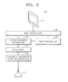
- FIG. 3 is a diagram showing a structure of the apparatus 100 for realizing a synchronization image, according to another embodiment of the present invention.
- the apparatus 100 further includes an ultrasonic transmission/reception control unit 140, a beam former 150, a tissue tracking unit 160, and a display unit 170 in addition to the transducer 110, the vector component obtaining unit 120, and the image realizing unit 130 shown in FIG. 2 .
- the transducer 110, the vector component obtaining unit 120, and the image realizing unit 130 shown in FIG. 3 have the same technical spirit as those shown in FIG. 2 , and thus will not be described in detail.
- the ultrasonic transmission/reception control unit 140 controls the transducer 110 to transmit an ultrasonic signal to an object and to receive an echo signal from the object.
- Echo signals received through the transducer 110 are sent to the beam former 150, which collects a plurality of received echo signals and converts them into a signal.
- a distance between each of a plurality of elements included in the transducer 110 and a target tissue varies from element to element, such that the plurality of echo signals reflected from the tissue are not received at the same time point. Therefore, the beam former 150 applies a time delay to the plurality of received echo signals to convert them into a single signal.
- the tissue tracking unit 160 tracks the velocity magnitude and the velocity direction of each tissue of the object based on the vector component obtained by the vector component obtaining unit 120.
- the display unit 170 displays the synchronization image realized by the image realizing unit 130 to enable a user to identify the synchronization image.
- FIG. 4 is a diagram for describing how to obtain a vector component of a tissue of an object 200 by the apparatus 100 for realizing a synchronization image, according to an embodiment of the present invention.
- the transducer 110 transmits a first ultrasonic signal S 1 and a second ultrasonic signal S 2 to a tissue P of the object 200.
- the tissue P moves in a direction A with a velocity vector v .
- the frequencies of the ultrasonic signals S 1 and S 2 are changed due to the tissue P moving in the direction A, and frequency-changed echo signals may be received by the transducer 110.
- FIG. 5 is a diagram for describing how to obtain a vector component of a tissue of the object 200 by the apparatus 100 for realizing a synchronization image, according to another embodiment of the present invention.
- a velocity vector v 1 and a velocity vector v 2 may be obtained.
- the ultrasonic signal S 1 is reflected by the tissue P and transmitted to the transducer 110, and in this case, a generated Doppler signal corresponds to the velocity vector v 1 .
- the ultrasonic signal S 2 is reflected by the tissue P and transmitted to the transducer 110, and in this case, a generated Doppler signal corresponds to the velocity vector v 2 .
- one-dimensional (1 D) straight lines w 1 and w 2 which are perpendicular to the velocity vectors v 1 and v 2 , respectively, may be derived as below.
- Equations 9 and 10 are coordinates of A.
- the vector component including the velocity magnitude and the velocity direction of the tissue P are obtained.
- FIGS. 6A and 6B are graphs for describing examples of a method of realizing a synchronization image by the apparatus 100 for realizing a synchronization image, according to an embodiment of the present invention or another embodiment of the present invention.
- FIG. 6A is a graph showing velocity magnitudes v of tissues A, B, and C of an object with respect to time.
- Time t 1 indicates a time point at which the tissues A and B reach peak velocity magnitudes
- t 2 indicates a time point at which the tissue C reaches a peak velocity magnitude
- the image realizing unit 130 may realize a synchronization image by using a velocity magnitude of each tissue. That is, the image realizing unit 130 may realize the synchronization image by using time differences among time points at which the velocity magnitudes of respective tissues reach a predetermined rate of their peak velocity magnitudes.
- the predetermined rate is set to 100% for an object for which synchronization has been completed, then time points at which respective tissues reach their peak velocity magnitudes have to coincide with each other. If the predetermined rate is set to 0% for an object for which synchronization has been completed, then time points at which velocity magnitudes of respective tissues reach 0 have to coincide with each other.
- a time point at which the velocity magnitude of each tissue reaches 0 means a time point prior to contraction of the object after expansion of the object or a time point prior to expansion of the object after contraction of the object.
- FIG. 6B is a graph showing displacements d of the tissues A, B, and C of the object with respect to time.
- the 'displacement' means the amount of change in position, and is defined as a vector quantity having a magnitude and a direction.
- Time t 1 indicates a time point at which displacements of the tissues A and B become 0, and t 2 indicates a time point at which a displacement of the tissue C becomes 0.
- the vector component obtaining unit 120 obtains a displacement of each tissue by using the obtained vector component, and the image realizing unit 130 may realize the synchronization image by using the displacement of each tissue. That is, the image realizing unit 130 may realize the synchronization image by using time differences among time points at which displacements of respective tissues reach a predetermined rate of their peak displacements.
- the respective tissues of the object may be regarded as having been synchronized with each other.
- FIG. 7 is a diagram for describing an example of a method of realizing a synchronization image by the apparatus 100 for realizing a synchronization image, according to an embodiment of the present invention or another embodiment of the present invention.
- the vector component obtaining unit 120 may set an arbitrary position S in the object and obtain a velocity magnitude v' in a direction toward the set position S from a velocity magnitude of each tissue of the object, and the image realizing unit 130 may realize a synchronization image by using the velocity magnitude v' of each tissue in the direction toward the set position S.
- a user or an ultrasonic device may set the arbitrary position S in the object, and the vector component obtaining unit 120 may obtain the velocity magnitude v' in the direction toward the set position S from the velocity magnitude v of the tissue P.
- the image realizing unit 130 may realize the synchronization image by using time differences among time points at which velocity magnitudes of respective tissues of the object in the direction toward the set position reach a predetermined rate of their peak velocity magnitudes in the direction toward the set position. In this way, the synchronization image may be realized based on the position desired by the user or the ultrasonic device.
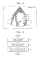
- FIG. 8 is a synchronization image of the heart.
- the image realizing unit 130 of the apparatus 100 may realize a synchronization image by expressing time differences among time points described with reference to FIGS. 6A and 6B in a color scale. That is, a difference between time points at which velocity magnitudes of respective tissues reach a predetermined rate of their peak velocity magnitudes, a difference between time points at which displacements of respective tissues reach a predetermined rate of their peak displacements, and so forth are expressed in a color scale.
- a portion indicated by 'X' is a synchronization image for the tissue C of FIGS. 6A and 6B .
- FIG. 9 is a flowchart of a method of realizing a synchronization image, according to an embodiment of the present invention.
- the method includes operations that are time-serially processed by the apparatus 100 shown in FIGS. 2 and 3 . Therefore, although omitted, the above description of the apparatus 100 shown in FIGS. 2 and 3 also applies to the method shown in FIG. 9 .
- the transducer 110 transmits an ultrasonic signal to an object including at least two tissues.
- the transducer 110 may receive an echo signal reflected from the object.
- the transducer 110 may transmit an ultrasonic signal to at least two different tissues in the object.
- the vector component obtaining unit 120 obtains a vector component of each tissue of the object based on the received echo signal.
- the vector component of each tissue may include velocity magnitude and velocity direction of each tissue.
- the image realizing unit 130 realizes a synchronization image by using the vector component of each tissue of the object.
- the synchronization image may be realized in a color scale.
- the above-described embodiments of the present invention can be implemented as a program which can be executed by a computer, and may be implemented on a general-purpose digital computer which runs the program by using a computer-readable recording medium.
- the computer-readable recording medium may include a magnetic storage medium (e.g., ROMs, floppy disks, hard disks, etc.), optical reading medium (e.g., CD-ROMs, DVDs, etc.), etc.
- a magnetic storage medium e.g., ROMs, floppy disks, hard disks, etc.
- optical reading medium e.g., CD-ROMs, DVDs, etc.
- the method and apparatus for realizing a synchronization image obtain vector components of tissues of the object, thereby obtaining velocity magnitude and velocity direction of motions of the respective tissues.
- the method and apparatus for realizing a synchronization image accurately measure horizontal-direction velocity magnitudes of tissues of the object, thereby improving the accuracy of a synchronization image of the object.
Landscapes
- Engineering & Computer Science (AREA)
- Health & Medical Sciences (AREA)
- Physics & Mathematics (AREA)
- Life Sciences & Earth Sciences (AREA)
- Radar, Positioning & Navigation (AREA)
- Remote Sensing (AREA)
- Medical Informatics (AREA)
- Public Health (AREA)
- Acoustics & Sound (AREA)
- General Physics & Mathematics (AREA)
- General Health & Medical Sciences (AREA)
- Pathology (AREA)
- Biomedical Technology (AREA)
- Computer Networks & Wireless Communication (AREA)
- Nuclear Medicine, Radiotherapy & Molecular Imaging (AREA)
- Animal Behavior & Ethology (AREA)
- Surgery (AREA)
- Molecular Biology (AREA)
- Veterinary Medicine (AREA)
- Heart & Thoracic Surgery (AREA)
- Radiology & Medical Imaging (AREA)
- Biophysics (AREA)
- Computer Vision & Pattern Recognition (AREA)
- Physiology (AREA)
- Data Mining & Analysis (AREA)
- Databases & Information Systems (AREA)
- Epidemiology (AREA)
- Primary Health Care (AREA)
- Multimedia (AREA)
- Theoretical Computer Science (AREA)
- Ultra Sonic Daignosis Equipment (AREA)
Abstract
Description
- This application claims the benefit of Korean Patent Application No.
10-2012-0002033, filed on January 6, 2012 - The present invention relates to an apparatus and method for realizing a synchronization image indicating whether motions of an object have been synchronized.
- Ultrasonic devices are essential equipment for observing an internal structure of an organism. An ultrasonic device, which is a non-invasive inspection device, shows structural details, internal tissues, and flow of fluids in the body.
- The ultrasonic device transmits an ultrasonic signal to an object through a body, receives an echo signal reflected from the object, and renders an internal structure of the body into an image.
- Inside the body, an object which periodically moves, such as the heart, exists and motions of tissues of the object have to be synchronized with each other. To determine whether the motions of the tissues of the object have been synchronized, a synchronization image produced by the ultrasonic device is mainly used.
- A synchronization image is an image regarding motions of an object, and by observing the synchronization image, a tissue which has not been synchronized with other tissues of the object may be discovered.
- The present invention provides a method and apparatus for realizing a synchronization image, in which vector components of tissues of an object are obtained to obtain a velocity magnitude and a velocity direction of each of the tissues.
- The present invention also provides a method and apparatus for realizing a synchronization image, in which horizontal-direction velocity magnitudes of tissues of an object are accurately measured to improve the accuracy of a synchronization image of the object.
- According to an aspect of the present invention, there is provided a method of realizing a synchronization image, the method including transmitting an ultrasonic signal to an object, obtaining vector components of at least two points included in the object based on an echo signal reflected from the object, and realizing a synchronization image of the object, which indicates whether motions of the at least two points have been synchronized, by using the obtained vector component.
- The synchronization image may be a two-dimensional (2D) image or a three-dimensional (3D) image.
- The vector components of the at least two points may include velocity magnitudes and velocity directions of the at least two points.
- The realizing the synchronization image may include realizing the synchronization image by using time differences among time points at which each of the velocity magnitudes of the at least two points reach a predetermined rate of each of corresponding peak velocity magnitudes of at least two points.
- The method may further include obtaining displacements of the at least two points by using the obtained vector components, in which the realizing the synchronization image includes realizing the synchronization image by using time differences among time points at which each of the displacements of the at least two points reach a predetermined rate of each of corresponding peak displacements of the at least two points.
- The method may further include setting an arbitrary position in the object and obtaining velocity magnitudes in a direction toward the set position from the velocity magnitudes of the at least two points by using the obtained vector components, in which the realizing the synchronization image includes realizing the synchronization image by using time differences among time points at which each of the velocity magnitudes of the at least two points in the direction toward the set position reach a predetermined rate of each of corresponding peak velocity magnitudes of the at least two points in the direction toward the set position.
- The method may further include displaying the realized synchronization image.
- The realizing the synchronization image may include realizing the synchronization image by expressing the time differences among time points in a color scale.
- According to another aspect of the present invention, there is provided an apparatus for realizing a synchronization image, the apparatus including a transducer for transmitting an ultrasonic signal to an object; a vector component obtaining unit for obtaining vector components of at least two points included in the object based on an echo signal reflected from the object; and an image realizing unit for realizing a synchronization image of the object, which indicates whether motions of the at least two points have been synchronized, by using the obtained vector component.
- The synchronization image may be a two-dimensional (2D) image or a three-dimensional (3D) image.
- The vector components of the at least two points may include velocity magnitudes and velocity directions of the at least two points.
- The image realizing unit may realize the synchronization image by using time differences among time points at which each of the velocity magnitudes of the at least two points reach a predetermined rate of each of corresponding peak velocity magnitudes of the at least two points.
- The vector component obtaining unit may obtain displacements of the at least two points by using the obtained vector components, and the image realizing unit may realize the synchronization image by using time differences among time points at which each of the displacements of the at least two points reach a predetermined rate of each of corresponding peak displacements of the at least two points.
- The vector component obtaining unit may set an arbitrary position in the object and obtains velocity magnitudes in a direction toward the set position from the velocity magnitudes of the at least two points by using the obtained vector components, and the image realizing unit may realize the synchronization image by using time differences among time points at which each of the velocity magnitudes of the at least two points in the direction toward the set position reach a predetermined rate of each of corresponding peak velocity magnitudes of the at least two points in the direction toward the set position.
- The apparatus may further include a display unit for displaying the realized synchronization image.
- The image realizing unit may realize the synchronization image by expressing the time differences among time points in a color scale.
- The transducer may comprise a 2D matrix probe.
- According to another aspect of the present invention, there is provided a computer-readable recording medium having recorded thereon a computer program for executing the method of realizing a synchronization image.
- According to another aspect of the present invention, there is provided an ultrasonic device including the apparatus for realizing a synchronization image.
- The above and other features and advantages of the present invention will become more apparent by describing in detail exemplary embodiments thereof with reference to the attached drawings in which:
-
FIG. 1 is a diagram for describing a conventional method of realizing a synchronization image; -
FIG. 2 is a diagram showing a structure of an apparatus for realizing a synchronization image, according to an embodiment of the present invention; -
FIG. 3 is a diagram showing a structure of an apparatus for realizing a synchronization image, according to another embodiment of the present invention; -
FIG. 4 is a diagram for describing how to obtain a vector component of a tissue of an object by an apparatus for realizing a synchronization image, according to an embodiment of the present invention; -
FIG. 5 is a diagram for describing how to obtain a vector component of a tissue of an object by an apparatus for realizing a synchronization image, according to another embodiment of the present invention; -
FIGS. 6A and 6B are graphs for describing examples of a method of realizing a synchronization image by an apparatus for realizing a synchronization image, according to an embodiment of the present invention or another embodiment of the present invention; -
FIG. 7 is a diagram for describing an example of a method of realizing a synchronization image by an apparatus for realizing a synchronization image, according to an embodiment of the present invention or another embodiment of the present invention; -
FIG. 8 is a synchronization image of the heart; and -
FIG. 9 is a flowchart of a method of realizing a synchronization image, according to an embodiment of the present invention. - Advantages and features of the present invention and a method for achieving them will become apparent from embodiments described below in detail with reference to the accompanying drawings. However, the present invention is not limited to the disclosed embodiments and may be implemented in different forms. The embodiments are provided to complete the disclosure of the present invention and to allow those of ordinary skill in the art to fully understand the scope of the present invention, and the present invention is defined merely by the claims. Throughout the specification, like reference numerals refer to like components.
- Terms 'part' used in the embodiments means a software or a hardware component such as a field-programmable gate array (FPGA) or an application-specific integrated circuit (ASIC), and a 'part' plays a certain role. However, the 'part' does not have a meaning limited to software or hardware. The 'part' may be configured to be in a storage medium capable of addressing, or may be configured to execute one or more processors. Therefore, as an example, the 'part' includes components such as software components, object-oriented software components, class components, and task components, and processes, functions, attributes, procedures, subroutines, segments of a program code, drivers, firmware, a micro code, a circuit, data, a database, data structures, tables, arrays, and variables. Functions provided in components and 'parts' may be combined into a smaller number of components and 'parts' or may be further separated into additional components and 'parts'.
-
FIG. 1 is a diagram for describing a conventional method of realizing a synchronization image. - A general ultrasonic device realizes a synchronization image of an
object 20 by using the Doppler effect. - The
object 20 means an organ in a body or a particular region in the body for which an ultrasonic image is to be obtained. In addition, in the specification, a 'tissue' means a cell or a group of cells which forms theobject 20. - A tissue P of the
object 20 moves in a direction A with a velocity magnitude v.A transducer 10 of the general ultrasonic device, once transmitting an ultrasonic signal having a frequency f0 to the tissue P, then receives an echo signal reflected from the tissue P. The frequency of the echo signal changes according to the velocity magnitude v of the tissue P and an angle θ between an output direction of the ultrasonic signal and a movement direction of the tissue P; a difference between a frequency of the ultrasonic signal transmitted to the tissue P and a frequency of the echo signal is referred to as a Doppler frequency. A signal having the Doppler frequency is called a Doppler signal. - The general ultrasonic device obtains a velocity magnitude of each tissue by measuring a Doppler frequency received from each tissue of the
object 20, and realizes a synchronization image of theobject 20 based on whether time points at which velocity magnitudes of respective tissues reach peak velocity magnitudes of respective tissues coincide with each other. - However, since respective tissues of the
object 20 have different velocity directions, the general ultrasonic device cannot accurately measure an angle between the movement direction of each tissue and the transmitted ultrasonic signal. As a result, if an angle between the movement direction of each tissue and the ultrasonic signal transmitted to the tissue is 0 degrees, the general ultrasonic device may accurately measure the velocity magnitude of the tissue, but may not accurately measure the lateral-direction velocity magnitude of the tissue moving in another direction, making it impossible to realize an accurate synchronization image. - Herein, the 'velocity magnitude' is a scalar quantity that indicates only the magnitude of a velocity and not a direction. The 'velocity direction' means a direction in which a particular object or a particular point of an object desires to move at an arbitrary time point.
-
FIG. 2 is a diagram showing a structure of anapparatus 100 for realizing a synchronization image, according to an embodiment of the present invention. - The
apparatus 100 for realizing a synchronization image may be included in an ultrasonic device or may be implemented as a microchip. - Referring to
FIG. 2 , theapparatus 100 may include atransducer 110, a vectorcomponent obtaining unit 120, and animage realizing unit 130. - The
transducer 110 transmits an ultrasonic signal to an object. Thetransducer 110 may also receive an echo signal reflected from the object. Thetransducer 110 may comprises a 2D matrix probe. - The
transducer 110 includes a plurality of elements including piezoelectric devices, and each element transmits an ultrasonic signal. - The object may include at least two points. The at least two points according to an embodiment of the present invention may be different tissues in the object or may be different points in the same tissue. In the following description, for convenience's sake, an example in which the at least two points are different tissues in the object is described.
- The
transducer 110 transmits an ultrasonic signal to each of the tissues of the object, and receives a reflected echo signal. Thetransducer 110 may transmit the ultrasonic signal to different points in the object and receive the reflected echo signal. - The vector
component obtaining unit 120 obtains a vector component of a tissue based on the echo signal reflected from the tissue of the object. The vector component of the tissue may include a velocity magnitude and a velocity direction of the tissue. The vectorcomponent obtaining unit 120 may obtain the velocity magnitude and the velocity direction of the tissue based on a Doppler frequency included in the echo signal. - How the vector
component obtaining unit 120 obtains the vector component is described in detail below with reference toFIGS. 4 and 5 . - The
image realizing unit 130 realizes a synchronization image of the object, which indicates whether motions of the tissues of the object have been synchronized, by using the vector component obtained by the vectorcomponent obtaining unit 120. Theimage realizing unit 130 may realize the synchronization image as a 2D image or a 3D image. - How the
image realizing unit 130 realizes the synchronization image is described in detail below with reference toFIG. 6 . -
FIG. 3 is a diagram showing a structure of theapparatus 100 for realizing a synchronization image, according to another embodiment of the present invention. - Referring to
FIG. 3 , theapparatus 100 further includes an ultrasonic transmission/reception control unit 140, a beam former 150, atissue tracking unit 160, and adisplay unit 170 in addition to thetransducer 110, the vectorcomponent obtaining unit 120, and theimage realizing unit 130 shown inFIG. 2 . - The
transducer 110, the vectorcomponent obtaining unit 120, and theimage realizing unit 130 shown inFIG. 3 have the same technical spirit as those shown inFIG. 2 , and thus will not be described in detail. - The ultrasonic transmission/
reception control unit 140 controls thetransducer 110 to transmit an ultrasonic signal to an object and to receive an echo signal from the object. - Echo signals received through the
transducer 110 are sent to the beam former 150, which collects a plurality of received echo signals and converts them into a signal. A distance between each of a plurality of elements included in thetransducer 110 and a target tissue varies from element to element, such that the plurality of echo signals reflected from the tissue are not received at the same time point. Therefore, the beam former 150 applies a time delay to the plurality of received echo signals to convert them into a single signal. - The
tissue tracking unit 160 tracks the velocity magnitude and the velocity direction of each tissue of the object based on the vector component obtained by the vectorcomponent obtaining unit 120. - The
display unit 170 displays the synchronization image realized by theimage realizing unit 130 to enable a user to identify the synchronization image. -
FIG. 4 is a diagram for describing how to obtain a vector component of a tissue of anobject 200 by theapparatus 100 for realizing a synchronization image, according to an embodiment of the present invention. - The
transducer 110 transmits a first ultrasonic signal S1 and a second ultrasonic signal S2 to a tissue P of theobject 200. The tissue P moves in a direction A with a velocity vectorv . The frequencies of the ultrasonic signals S1 and S2 are changed due to the tissue P moving in the direction A, and frequency-changed echo signals may be received by thetransducer 110. -
FIG. 5 is a diagram for describing how to obtain a vector component of a tissue of theobject 200 by theapparatus 100 for realizing a synchronization image, according to another embodiment of the present invention. - Once the velocity vector
v of the tissue P is projected in a vertical direction, a velocity vectorv 1 and a velocity vectorv 2 may be obtained. The ultrasonic signal S1 is reflected by the tissue P and transmitted to thetransducer 110, and in this case, a generated Doppler signal corresponds to the velocity vectorv 1. The ultrasonic signal S2 is reflected by the tissue P and transmitted to thetransducer 110, and in this case, a generated Doppler signal corresponds to the velocity vectorv 2. - By letting an angle difference between an y axis and the velocity vector
v 1 be θ1 and an angle difference between the y axis and the velocity vectorv 2 be θ2, the following equations are derived with respect to the velocity vectorsv 1, andv 2.

- By letting velocity magnitudes of the velocity vectors
v 1 andv 2 be v1 and v2, respectively, one-dimensional (1 D) straight lines w1 and w2, which are perpendicular to the velocity vectorsv 1 andv 2, respectively, may be derived as below.

- The velocity magnitudes v1 and v2 have the following relationship with the Doppler frequencies of the ultrasonic signals S1 and S2:

wherein Δfn indicates a Doppler frequency, f indicates the frequencies of the ultrasonic signals S1 and S2, c indicates the sound speeds of the ultrasonic signals S1 and S2, and n is an integer. - Since the ultrasonic signals S1 and S2 are transmitted to a tissue in opposite directions, but with the same angle, θ1 and θ2 have the following relationship.


- By using Equations 6, 7, and 8, an intersection of Equations 3 and 4 is calculated, from which the following equations are derived.


x and y ofEquations 9 and 10 are coordinates of A. - By using
Equations 9 and 10, the velocity magnitude v and an angle Φ with the y axis of the velocity vectorv are derived as follows:

- From the calculated velocity magnitude and angle Φ of the velocity vector
v , the vector component including the velocity magnitude and the velocity direction of the tissue P are obtained. -
FIGS. 6A and 6B are graphs for describing examples of a method of realizing a synchronization image by theapparatus 100 for realizing a synchronization image, according to an embodiment of the present invention or another embodiment of the present invention. -
FIG. 6A is a graph showing velocity magnitudes v of tissues A, B, and C of an object with respect to time. - Time t1 indicates a time point at which the tissues A and B reach peak velocity magnitudes, and t2 indicates a time point at which the tissue C reaches a peak velocity magnitude.
- The
image realizing unit 130 may realize a synchronization image by using a velocity magnitude of each tissue. That is, theimage realizing unit 130 may realize the synchronization image by using time differences among time points at which the velocity magnitudes of respective tissues reach a predetermined rate of their peak velocity magnitudes. - For example, if the predetermined rate is set to 100% for an object for which synchronization has been completed, then time points at which respective tissues reach their peak velocity magnitudes have to coincide with each other. If the predetermined rate is set to 0% for an object for which synchronization has been completed, then time points at which velocity magnitudes of respective tissues reach 0 have to coincide with each other. A time point at which the velocity magnitude of each tissue reaches 0 means a time point prior to contraction of the object after expansion of the object or a time point prior to expansion of the object after contraction of the object.
- Referring to
FIG. 6A , it can be seen that time points at which the tissues A and B reach their peak velocity magnitudes coincide with each other, but a time point at which the tissue C reaches its peak velocity magnitude is different from those at which the tissues A and B reach their peak velocity magnitudes. Hence, it can be known that in the object, the tissue C has not been synchronized. -
FIG. 6B is a graph showing displacements d of the tissues A, B, and C of the object with respect to time. - The 'displacement' means the amount of change in position, and is defined as a vector quantity having a magnitude and a direction.
- Time t1 indicates a time point at which displacements of the tissues A and B become 0, and t2 indicates a time point at which a displacement of the tissue C becomes 0.
- The vector
component obtaining unit 120 obtains a displacement of each tissue by using the obtained vector component, and theimage realizing unit 130 may realize the synchronization image by using the displacement of each tissue. That is, theimage realizing unit 130 may realize the synchronization image by using time differences among time points at which displacements of respective tissues reach a predetermined rate of their peak displacements. - For example, if time points at which displacements of respective tissues become 0 coincide with each other for a predetermined rate of 0%, the respective tissues of the object may be regarded as having been synchronized with each other.
- Referring to
FIG. 6B , time points at which displacements of the tissues A and B reach 0 coincide with each other, but a time point at which the displacement of the tissue C reaches 0 is different from those at which displacements of the tissues A and B reach 0. Therefore, it can be determined that the in the object, the tissue C has not been synchronized. -
FIG. 7 is a diagram for describing an example of a method of realizing a synchronization image by theapparatus 100 for realizing a synchronization image, according to an embodiment of the present invention or another embodiment of the present invention. - According to another embodiment of the present invention, the vector
component obtaining unit 120 may set an arbitrary position S in the object and obtain a velocity magnitude v' in a direction toward the set position S from a velocity magnitude of each tissue of the object, and theimage realizing unit 130 may realize a synchronization image by using the velocity magnitude v' of each tissue in the direction toward the set position S. - More specifically, a user or an ultrasonic device may set the arbitrary position S in the object, and the vector
component obtaining unit 120 may obtain the velocity magnitude v' in the direction toward the set position S from the velocity magnitude v of the tissue P. The velocity magnitude v' of the tissue P in the direction toward the set position S may be obtained by using an angle difference θ between the tissue P and the set position S and the velocity magnitude v of the tissue P (v' = v · cos θ). - The
image realizing unit 130 may realize the synchronization image by using time differences among time points at which velocity magnitudes of respective tissues of the object in the direction toward the set position reach a predetermined rate of their peak velocity magnitudes in the direction toward the set position. In this way, the synchronization image may be realized based on the position desired by the user or the ultrasonic device. -
FIG. 8 is a synchronization image of the heart. - The
image realizing unit 130 of theapparatus 100 according to another embodiment of the present invention may realize a synchronization image by expressing time differences among time points described with reference toFIGS. 6A and 6B in a color scale. That is, a difference between time points at which velocity magnitudes of respective tissues reach a predetermined rate of their peak velocity magnitudes, a difference between time points at which displacements of respective tissues reach a predetermined rate of their peak displacements, and so forth are expressed in a color scale. A portion indicated by 'X' is a synchronization image for the tissue C ofFIGS. 6A and 6B . -
FIG. 9 is a flowchart of a method of realizing a synchronization image, according to an embodiment of the present invention. Referring toFIG. 9 , the method includes operations that are time-serially processed by theapparatus 100 shown inFIGS. 2 and3 . Therefore, although omitted, the above description of theapparatus 100 shown inFIGS. 2 and3 also applies to the method shown inFIG. 9 . - In operation S10, the
transducer 110 transmits an ultrasonic signal to an object including at least two tissues. In addition, thetransducer 110 may receive an echo signal reflected from the object. Thetransducer 110 may transmit an ultrasonic signal to at least two different tissues in the object. - In operation S20, the vector
component obtaining unit 120 obtains a vector component of each tissue of the object based on the received echo signal. The vector component of each tissue may include velocity magnitude and velocity direction of each tissue. - In operation S30, the
image realizing unit 130 realizes a synchronization image by using the vector component of each tissue of the object. The synchronization image may be realized in a color scale. - The above-described embodiments of the present invention can be implemented as a program which can be executed by a computer, and may be implemented on a general-purpose digital computer which runs the program by using a computer-readable recording medium.
- The computer-readable recording medium may include a magnetic storage medium (e.g., ROMs, floppy disks, hard disks, etc.), optical reading medium (e.g., CD-ROMs, DVDs, etc.), etc.
- The method and apparatus for realizing a synchronization image, according to embodiments of the present invention, obtain vector components of tissues of the object, thereby obtaining velocity magnitude and velocity direction of motions of the respective tissues.
- Moreover, the method and apparatus for realizing a synchronization image, according to embodiments of the present invention, accurately measure horizontal-direction velocity magnitudes of tissues of the object, thereby improving the accuracy of a synchronization image of the object.
- While the present invention has been particularly shown and described with reference to exemplary embodiments thereof, it will be understood by those of ordinary skill in the art that the present invention may also be cared out in other concrete forms without changing the technical spirit or essential features of the present invention. Therefore, the above-described embodiments have to be construed as illustrative rather than restrictive.
Claims (15)
- A method of realizing a synchronization image, the method comprising:transmitting an ultrasonic signal to an object;obtaining vector components of at least two points included in the object based on an echo signal reflected from the object; andrealizing a synchronization image of the object, which indicates whether motions of the at least two points have been synchronized, by using the obtained vector component.
- The method of claim 1, wherein the synchronization image is a two-dimensional (2D) image or a three-dimensional (3D) image.
- The method of claim 1, wherein the vector components of the at least two points comprise velocity magnitudes and velocity directions of the at least two points.
- The method of claim 3, wherein the realizing the synchronization image comprises realizing the synchronization image by using time differences among time points at which each of the velocity magnitudes of the at least two points reach a predetermined rate of each of corresponding peak velocity magnitudes of the at least two points.
- The method of claim 3, further comprising:obtaining displacements of the at least two points by using the obtained vector components,wherein the realizing the synchronization image comprises realizing the synchronization image by using time differences among time points at which each of the displacements of the at least two points reach a predetermined rate of each of corresponding peak displacements of the at least two points.
- The method of claim 3, further comprising:setting an arbitrary position in the object; andobtaining velocity magnitudes in a direction toward the set position from the velocity magnitudes of the at least two points by using the obtained vector components,wherein the realizing the synchronization image comprises realizing the synchronization image by using time differences among time points at which each of the velocity magnitudes of the at least two points in the direction toward the set position reach a predetermined rate of each of corresponding peak velocity magnitudes of the at least two points in the direction toward the set position.
- The method of claim 1, further comprising displaying the realized synchronization image.
- The method of claim 4, wherein the realizing the synchronization image comprises realizing the synchronization image by expressing the time differences among time points in a color scale.
- An apparatus for realizing a synchronization image, the apparatus comprising:a transducer for transmitting an ultrasonic signal to an object;a vector component obtaining unit for obtaining vector components of at least two points included in the object based on an echo signal reflected from the object; andan image realizing unit for realizing a synchronization image of the object, which indicates whether motions of the at least two points have been synchronized, by using the obtained vector component.
- The apparatus of claim 9, wherein the vector components of the at least two points comprise velocity magnitudes and velocity directions of the at least two points.
- The apparatus of claim 10, wherein the image realizing unit realizes the synchronization image by using time differences among time points at which each of the velocity magnitudes of the at least two points reach a predetermined rate of each of corresponding peak velocity magnitudes of the at least two points.
- The apparatus of claim 10, wherein the vector component obtaining unit obtains displacements of the at least two points by using the obtained vector components, and the image realizing unit realizes the synchronization image by using time differences among time points at which each of the displacements of the at least two points reach a predetermined rate of each of corresponding peak displacements of the at least two points.
- The apparatus of claim 10, wherein the vector component obtaining unit sets an arbitrary position in the object and obtains velocity magnitudes in a direction toward the set position from the velocity magnitudes of the at least two points by using the obtained vector components, and
the image realizing unit realizes the synchronization image by using time differences among time points at which each of the velocity magnitudes of the at least two points in the direction toward the set position reach a predetermined rate of each of corresponding peak velocity magnitudes of the at least two points in the direction toward the set position. - The apparatus of claim 9, wherein the transducer comprises a 2D matrix probe.
- A computer-readable recording medium having recorded thereon a computer program for executing a method of anyone of claims 1 through 8.
Applications Claiming Priority (1)
| Application Number | Priority Date | Filing Date | Title |
|---|---|---|---|
| KR1020120002033A KR101323332B1 (en) | 2012-01-06 | 2012-01-06 | Apparatus and method for realizing synchronization image |
Publications (1)
| Publication Number | Publication Date |
|---|---|
| EP2612601A1 true EP2612601A1 (en) | 2013-07-10 |
Family
ID=47681623
Family Applications (1)
| Application Number | Title | Priority Date | Filing Date |
|---|---|---|---|
| EP13150129.8A Withdrawn EP2612601A1 (en) | 2012-01-06 | 2013-01-03 | Apparatus and method for realizing synchronization image |
Country Status (3)
| Country | Link |
|---|---|
| US (1) | US9354309B2 (en) |
| EP (1) | EP2612601A1 (en) |
| KR (1) | KR101323332B1 (en) |
Families Citing this family (1)
| Publication number | Priority date | Publication date | Assignee | Title |
|---|---|---|---|---|
| JP7011590B2 (en) | 2015-10-12 | 2022-02-10 | イー・アイ・デュポン・ドウ・ヌムール・アンド・カンパニー | Protected DNA template and method of use for increased intracellular gene recombination and homologous recombination |
Citations (3)
| Publication number | Priority date | Publication date | Assignee | Title |
|---|---|---|---|---|
| EP0228069A2 (en) * | 1985-12-26 | 1987-07-08 | Aloka Co. Ltd. | Ultrasonic blood flow imaging apparatus |
| US5622174A (en) * | 1992-10-02 | 1997-04-22 | Kabushiki Kaisha Toshiba | Ultrasonic diagnosis apparatus and image displaying system |
| WO2002045587A1 (en) * | 2000-12-07 | 2002-06-13 | Koninklijke Philips Electronics N.V. | Strain rate analysis in ultrasonic diagnostic images |
Family Cites Families (12)
| Publication number | Priority date | Publication date | Assignee | Title |
|---|---|---|---|---|
| JP2001509724A (en) * | 1997-11-18 | 2001-07-24 | コーニンクレッカ フィリップス エレクトロニクス エヌ ヴィ | Signal processing method for object having moving part and echographic apparatus |
| US7175598B2 (en) * | 2002-06-18 | 2007-02-13 | Kabushiki Kaisha Toshiba | Ultrasound diagnosis apparatus that adjusts a time phase between a plurality of image series |
| AU2003302229A1 (en) * | 2002-09-27 | 2004-06-30 | The Trustees Of Dartmouth College | Imaging by magnetic resonance adsorption, elastography and tomography |
| US20050096543A1 (en) * | 2003-11-03 | 2005-05-05 | Jackson John I. | Motion tracking for medical imaging |
| JP4660126B2 (en) | 2004-06-18 | 2011-03-30 | 株式会社東芝 | Ultrasound blood flow imaging device |
| US20080081998A1 (en) | 2006-10-03 | 2008-04-03 | General Electric Company | System and method for three-dimensional and four-dimensional contrast imaging |
| US9173638B2 (en) * | 2007-06-04 | 2015-11-03 | Biosense Webster, Inc. | Cardiac mechanical assessment using ultrasound |
| JP5063216B2 (en) | 2007-06-27 | 2012-10-31 | 日立アロカメディカル株式会社 | Ultrasonic diagnostic apparatus and processing program |
| JP5240994B2 (en) * | 2008-04-25 | 2013-07-17 | 東芝メディカルシステムズ株式会社 | Ultrasonic diagnostic apparatus, ultrasonic image processing apparatus, and ultrasonic image processing program |
| KR101117868B1 (en) * | 2009-06-01 | 2012-03-07 | 삼성메디슨 주식회사 | Ultrasound system and method for providing comparision information of interest object |
| EP2417913A4 (en) * | 2009-04-06 | 2014-07-23 | Hitachi Medical Corp | MEDICAL IMAGING DIAGNOSIS DEVICE, INTEREST REGION DEFINITION METHOD, MEDICAL IMAGE PROCESSING DEVICE, AND REGION INTEREST DEFINITION PROGRAM |
| WO2010125452A1 (en) * | 2009-05-01 | 2010-11-04 | Palti Yoram Prof | Doppler based flow measurements |
-
2012
- 2012-01-06 KR KR1020120002033A patent/KR101323332B1/en active Active
-
2013
- 2013-01-03 EP EP13150129.8A patent/EP2612601A1/en not_active Withdrawn
- 2013-01-04 US US13/734,535 patent/US9354309B2/en active Active
Patent Citations (3)
| Publication number | Priority date | Publication date | Assignee | Title |
|---|---|---|---|---|
| EP0228069A2 (en) * | 1985-12-26 | 1987-07-08 | Aloka Co. Ltd. | Ultrasonic blood flow imaging apparatus |
| US5622174A (en) * | 1992-10-02 | 1997-04-22 | Kabushiki Kaisha Toshiba | Ultrasonic diagnosis apparatus and image displaying system |
| WO2002045587A1 (en) * | 2000-12-07 | 2002-06-13 | Koninklijke Philips Electronics N.V. | Strain rate analysis in ultrasonic diagnostic images |
Also Published As
| Publication number | Publication date |
|---|---|
| US9354309B2 (en) | 2016-05-31 |
| KR101323332B1 (en) | 2013-10-29 |
| KR20130081066A (en) | 2013-07-16 |
| US20130176824A1 (en) | 2013-07-11 |
Similar Documents
| Publication | Publication Date | Title |
|---|---|---|
| EP2356941B1 (en) | Ultrasonographic system | |
| CN105530870B (en) | Ultrasound imaging method and system | |
| EP2609868B1 (en) | Providing user interface in ultrasound system | |
| WO2016093024A1 (en) | Ultrasound diagnostic device and elasticity evaluation method | |
| JP2009268622A (en) | Ultrasonic measurement apparatus | |
| EP2609870A1 (en) | Providing turbulent flow information based on vector doppler in ultrasound system | |
| EP2766738B1 (en) | Three dimensional (3d) transverse oscillation vector velocity ultrasound imaging | |
| US9482646B2 (en) | Object information acquiring apparatus | |
| US9474510B2 (en) | Ultrasound and system for forming an ultrasound image | |
| US20130165784A1 (en) | Providing motion profile information of target object in ultrasound system | |
| US20090082668A1 (en) | Ultrasonic imaging apparatus and method for generating ultrasonic image | |
| EP2609866B1 (en) | Providing motion mode image in ultrasound system | |
| EP2610638B1 (en) | Forming vector information based on vector doppler in ultrasound system | |
| CN104856719A (en) | Ultrasonic measurement apparatus and ultrasonic measurement method | |
| JP6387856B2 (en) | Ultrasonic diagnostic apparatus and control method of ultrasonic diagnostic apparatus | |
| EP2610640B1 (en) | Ultrasound system and method for detecting vector information using transmission delays | |
| US10304226B2 (en) | Ultrasound focal zone system and method | |
| EP2609869A1 (en) | Providing particle flow image in ultrasound system | |
| EP2776860B1 (en) | Apparatus and method using elastic waves for acquiring moving information and program for executing the method | |
| US9354309B2 (en) | Apparatus and method for realizing synchronization image | |
| JP2013165922A (en) | Ultrasonic diagnostic apparatus | |
| JP2015128554A (en) | Ultrasonic diagnostic equipment | |
| JP2005152192A (en) | Ultrasonic diagnostic instrument | |
| JP2005130877A (en) | Ultrasonic diagnosis apparatus | |
| US20120226162A1 (en) | Ultrasound probe and ultrasound diagnostic apparatus |
Legal Events
| Date | Code | Title | Description |
|---|---|---|---|
| PUAI | Public reference made under article 153(3) epc to a published international application that has entered the european phase |
Free format text: ORIGINAL CODE: 0009012 |
|
| AK | Designated contracting states |
Kind code of ref document: A1 Designated state(s): AL AT BE BG CH CY CZ DE DK EE ES FI FR GB GR HR HU IE IS IT LI LT LU LV MC MK MT NL NO PL PT RO RS SE SI SK SM TR |
|
| AX | Request for extension of the european patent |
Extension state: BA ME |
|
| 17P | Request for examination filed |
Effective date: 20140110 |
|
| RBV | Designated contracting states (corrected) |
Designated state(s): AL AT BE BG CH CY CZ DE DK EE ES FI FR GB GR HR HU IE IS IT LI LT LU LV MC MK MT NL NO PL PT RO RS SE SI SK SM TR |
|
| 17Q | First examination report despatched |
Effective date: 20151023 |
|
| STAA | Information on the status of an ep patent application or granted ep patent |
Free format text: STATUS: THE APPLICATION IS DEEMED TO BE WITHDRAWN |
|
| 18D | Application deemed to be withdrawn |
Effective date: 20170127 |