EP2612399B1 - Cable plug and socket system for providing voltage selection - Google Patents
Cable plug and socket system for providing voltage selection Download PDFInfo
- Publication number
- EP2612399B1 EP2612399B1 EP11822254.6A EP11822254A EP2612399B1 EP 2612399 B1 EP2612399 B1 EP 2612399B1 EP 11822254 A EP11822254 A EP 11822254A EP 2612399 B1 EP2612399 B1 EP 2612399B1
- Authority
- EP
- European Patent Office
- Prior art keywords
- socket
- locator
- cable plug
- drum
- pin
- Prior art date
- Legal status (The legal status is an assumption and is not a legal conclusion. Google has not performed a legal analysis and makes no representation as to the accuracy of the status listed.)
- Active
Links
Images



Classifications
-
- H—ELECTRICITY
- H01—ELECTRIC ELEMENTS
- H01R—ELECTRICALLY-CONDUCTIVE CONNECTIONS; STRUCTURAL ASSOCIATIONS OF A PLURALITY OF MUTUALLY-INSULATED ELECTRICAL CONNECTING ELEMENTS; COUPLING DEVICES; CURRENT COLLECTORS
- H01R29/00—Coupling parts for selective co-operation with a counterpart in different ways to establish different circuits, e.g. for voltage selection, for series-parallel selection, programmable connectors
-
- H—ELECTRICITY
- H01—ELECTRIC ELEMENTS
- H01R—ELECTRICALLY-CONDUCTIVE CONNECTIONS; STRUCTURAL ASSOCIATIONS OF A PLURALITY OF MUTUALLY-INSULATED ELECTRICAL CONNECTING ELEMENTS; COUPLING DEVICES; CURRENT COLLECTORS
- H01R13/00—Details of coupling devices of the kinds covered by groups H01R12/70 or H01R24/00 - H01R33/00
- H01R13/66—Structural association with built-in electrical component
- H01R13/70—Structural association with built-in electrical component with built-in switch
- H01R13/701—Structural association with built-in electrical component with built-in switch the switch being actuated by an accessory, e.g. cover, locking member
-
- H—ELECTRICITY
- H01—ELECTRIC ELEMENTS
- H01R—ELECTRICALLY-CONDUCTIVE CONNECTIONS; STRUCTURAL ASSOCIATIONS OF A PLURALITY OF MUTUALLY-INSULATED ELECTRICAL CONNECTING ELEMENTS; COUPLING DEVICES; CURRENT COLLECTORS
- H01R24/00—Two-part coupling devices, or either of their cooperating parts, characterised by their overall structure
- H01R24/58—Contacts spaced along longitudinal axis of engagement
-
- H—ELECTRICITY
- H01—ELECTRIC ELEMENTS
- H01R—ELECTRICALLY-CONDUCTIVE CONNECTIONS; STRUCTURAL ASSOCIATIONS OF A PLURALITY OF MUTUALLY-INSULATED ELECTRICAL CONNECTING ELEMENTS; COUPLING DEVICES; CURRENT COLLECTORS
- H01R2103/00—Two poles
-
- H—ELECTRICITY
- H01—ELECTRIC ELEMENTS
- H01R—ELECTRICALLY-CONDUCTIVE CONNECTIONS; STRUCTURAL ASSOCIATIONS OF A PLURALITY OF MUTUALLY-INSULATED ELECTRICAL CONNECTING ELEMENTS; COUPLING DEVICES; CURRENT COLLECTORS
- H01R35/00—Flexible or turnable line connectors, i.e. the rotation angle being limited
Definitions
- PSU Power Supply Unit
- a universal PSU should be able to adapt its output characteristics to varied load devices requirements. Many today's PSU are already capable of such adaptation and their flexibility will increase in the future. However, the information regarding the load device characteristics have to be communicated to the PSU. Minimum human intervention should be involved in order to facilitate the characteristic selection.
- Universal PSU are in many cases designed with detachable output cables in order to increase portability.
- An output socket is integrated into PSU while the output cable is built with a matching jack.
- a variety of socket-jack systems are available today.
- US 4,367,907 A Magnetic Controls Company
- This system is used to monitor circuits and gain access to printed circuit boards. Again, the system is build for signal transfer and not power transfer. Also the way the output is chosen makes it impossible to use it for power transfer with different characteristics.
- US 2003/222503 A1 discloses a power distribution where the appropriate voltage level is selected automatically. In a first embodiment, this is done by using connectors comprising selected resistor installed therein which can produce a pre-determined control voltage which is fed back to an internal power supply which then controls the output voltage in dependency of the control voltage. In a second embodiment, the cable connector contains appropriate pins for a selected DC power usage device. In a third embodiment, a unique connector is attached to a universal cable and the connector employs only the appropriate pins for the selected voltage. In all of US 2003/222503 embodiments, each distinct voltage utilizes a unique connector.
- the present invention provides a cable plug configured for a socket-jack system that connects a PSU to a load device over a 2 wire cable.
- the cable plug is selectively moveable to one of a plurality of positions for selecting a predetermined output voltage (or other operational characteristic) for the load device.
- Figure 1 shows a classical connection between a PSU 100 and a load device 102 using a two-wire power cable 103.
- the PSU 100 shown in Figure 1 has DC output voltage and the load device (or devices) 102 are operating with DC input power.
- the socket is referenced generally by “S” and the cable plug (sometimes referred to as a “power connector plug”, “plug assembly” or just a “plug”) is referenced generally by “P”.
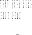
- FIG. 2(a) All four contacts are open when the cable jack is not plugged ( Figure 2(a) ), while one of the four contacts is closed when the jack cable is plugged in the corresponding position ( Figures 2 (b-e)).
- Figure 2a illustrates the plug disconnected.
- Fig. 2b illustrates the plug connected in a first position.
- Fig. 2c illustrates the plug connected in a second position.
- Fig. 2d illustrates the plug connected in a third position.
- Fig. 2e illustrates the plug connected in a fourth position.
- Other embodiments of the socket-cable plug function may achieve the closing of two or more contacts at the time.
- the S 1 - S4 connections are electrical signals that are used by the PSU to select a predetermined output voltage (or other characteristic for a given load device).
- S1 contact closed is selecting a PSU output voltage of 10.5V
- S2 contact closed is selecting a PSU output voltage of 12V
- S3 contact closed is selecting a PSU output voltage of 15.8V
- S4 contact closed is selecting a PSU output voltage of 19.5V.
- Figure 3 presents a general view of the cable plug P for a first embodiment of the socket-cable plug system, providing in this example four selector positions (following the electrical function described in 2.).
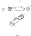
- FIG. 4 presents the same cable plug P with details regarding the selection of one of the four positions by rotating locator drum 1 against locking mechanism 6.
- Locator drum 1 features locking tabs that will be further locked into the receiving part of the socket S. Therefore rotating locking mechanism 6 in respect of locator drum 1 is equivalent with rotating locking mechanism 6 in respect of the receiving socket S.
- Locator drum 1 is constructed with a locking system against locking mechanism 6. The rotation between locator drum 1 and locking mechanism 6 is possible only when the locking system is disengaged by pushing it (pressed by finger). Hence a position between locator drum 1 and locking mechanism 6 can be changed only by human action; which means simultaneously pressing the locking system and rotating locator drum 1 against locking mechanism 6.
- Figure 5 shows the detailed construction of the plug assembly P, with locking mechanism 2 disassembled into component parts.
- the positive end connected terminal is indifferent to the locator drum 1 - locking mechanism 6 position, while the negative end connected terminal is sensitive to the locator drum 1 - locking mechanism 6 relative position.
- the matching socket S for the described plug of the first embodiment is shown in Figure 6 , showing an exterior view and also internal portions that are useful for this description.
- the socket body 9 features locking grooves 11 (also referred to as locking features) to match the locking tabs 34 of locking mechanism 6. Once the plug P is connected to the socket S, no rotation is possible between locator drum 1 and socket body 9.
- Pin (+) 4 is paired with the positive end terminal of the two wire cable, while pin (-) 5 is always connected to the negative end (ground) terminal of the plug.
- the contact between pin 5 and the negative end terminal of the plug is indifferent to the position of locking mechanism 6 against locator drum 1 and socket body 9 (locator drum and socket body are locket together when the plug P is connected to the socket S).
- the four signal pins 13 of the socket S are insolated between them and to the pin (+) 12 and ground (-) pin 14 by the isolator rings 30.
- Each of the signal pins 13 can connect with the negative end terminal 5 of the plug only when its respective position is selected through the locator tube 1 and locking mechanism 6 assembly.
- Figure 7 presents an expanded construction of the pins 12, 13, and 14, and Figure 8 presents a view of the socket-plug concept of this first embodiment, with the plug P connected to the socket S.
- Figure 9 presents the general method of obtaining four positions selector using the contact pins 4, 5 and 13 described herein by contacting one pin at a time or two pins at a time.
- the power plug P preferably comprises a rotatable locator drum 1 (e.g. an insulating body), a locator tube 2, an insulated center plastic tube 3 separating a conductive terminal "Pin (+)” 4 and a ground terminal “Pin (-)” 5, and a rotatable locking mechanism 6 with a voltage select indicator 36 to indicate voltage placement.
- a set of electrically conductive terminal and a ground terminal are formed by the insulating center plastic tube 3 having a pair of two insulated wires connected correspondingly to the conductive (+) terminal 4 and the signal/ground (-) terminal 5, thereby forming a center body.
- the terminal pin 4 is located inside the center plastic tube, and the terminal signal pin 5 is located on the outside of this plastic tube body 3.
- the entire center body is covered by the locator tube 2, the rotatable body (locator drum 1 encloses the center body; and comprises a ridged knob 8 that can be turned to a desired position (while pressing the locking mechanism 6 to lift the voltage tab 7, indicating the voltage selected for the device.
- This selection feature is accomplished by the locator tube 2 which turns the center insulated body fixing the location of the ground terminal 5 corresponding to the voltage selected via the locator drum 1.
- the voltage selection is completed by the locking mechanism 6 which serves as a locking system for the assembly and the voltage select indicator 36 for the power plug assembly.
- the socket S preferably comprises a thermo plastic body 9 with locking feature 11, and six conductive terminals; a center terminal pin 12 for the positive wire, four (4) ring terminals 13 for the signal pins and a ground ring terminal 14.
- the thermo plastic body 9 is arranged such that the center section of the thermo body 9 is insulating the positive wire terminal pin 12 while four (4) signal ring terminal 13 and a ground ring terminal 14 are arranged alternately separated by plastic ring around the insulated center section of the thermo body 9.
- the arrangement of the four (4) signal pin terminals 13 corresponds to the voltage selected for the device, the whole socket assembly has six (6) protruding holes for each terminal to be soldered to a printed circuit board (PCB).
- the locking feature 11 tabs along the face of the socket fixes the location of the power plug P and the selected voltage intended for the device.
- the present invention provides a cable plug configured for a socket-jack system that connects a PSU to a load device over a 2 wire cable.
- the cable plug is selectively moveable to one of a plurality of positions for selecting a predetermined output voltage (or other operational characteristic) for the load device.
- the foregoing description provides, among other features, a new and useful cable plug and socket system connecting a PSU to a load device over a 2 wire cable.
- the cable plug is selectively moveable to one of a plurality of positions for selecting a predetermined output voltage (or other operational characteristic) for the load device.
- a new and useful socket is provided, that is configured to mate with the cable plug, to provide the selected output voltage (or other operational characteristic) for the load device.
Landscapes
- Details Of Connecting Devices For Male And Female Coupling (AREA)
Description
- While Power Supply Units (PSU) are becoming more flexible and more intelligent, the mobile devices that are powered up by them are diversifying a lot, having different characteristic. Each consumer device is coming with its own PSU, which makes transportation difficult and reduces the mobility of the devices.
- A universal PSU should be able to adapt its output characteristics to varied load devices requirements. Many today's PSU are already capable of such adaptation and their flexibility will increase in the future. However, the information regarding the load device characteristics have to be communicated to the PSU. Minimum human intervention should be involved in order to facilitate the characteristic selection.
- Usually a minimum two wire electrical connection is used for power transfer between PSU and load device (two-wire power cable) and this is the cheapest way of power transfer. Hence a third wire ore more wires are necessary to establish the information transfer by electrical connection means. Prior art describes varies ways of communication by dedicated electrical connection. The information can be transferred in analog format, digital format or combinations of the two.
- Other prior art solutions are achieving PSU characteristic selection by means of an electric switch incorporated into the PSU, human intervention being required to place the switch in the desired position. The electrical switches used vary from the simplest (On/Off type) to more complex solutions where two or more combinations are possible.
- Universal PSU are in many cases designed with detachable output cables in order to increase portability. An output socket is integrated into PSU while the output cable is built with a matching jack. A variety of socket-jack systems are available today.
- One socket-jack system not intended for power supply but allowing the user to switch a microphone on and off by turning part of the plug is described in
US 7,618,294 B1 (Cheng Uei Precision Industries). But this technique is not suitable to choose anything else than just on and off like a power supply characteristic. Also this plug is merely for signal transmission and not for power transfer. - Another document describing a socket-jack system where the output can be controlled by positioning the plug is
US 4,367,907 A (Magnetic Controls Company). This system is used to monitor circuits and gain access to printed circuit boards. Again, the system is build for signal transfer and not power transfer. Also the way the output is chosen makes it impossible to use it for power transfer with different characteristics. -
US 2003/222503 A1 (Lam) discloses a power distribution where the appropriate voltage level is selected automatically. In a first embodiment, this is done by using connectors comprising selected resistor installed therein which can produce a pre-determined control voltage which is fed back to an internal power supply which then controls the output voltage in dependency of the control voltage. In a second embodiment, the cable connector contains appropriate pins for a selected DC power usage device. In a third embodiment, a unique connector is attached to a universal cable and the connector employs only the appropriate pins for the selected voltage. In all ofUS 2003/222503 embodiments, each distinct voltage utilizes a unique connector. - An apparatus comprising a cable plug and a socket configured for a socket-jack system for connecting a power supply unit to a load device according to the invention is disclosed in
independent claim 1. Further aspects of the invention are disclosed in the dependent claims. - Other features of the present invention will become apparent from the following detailed description and the accompanying drawings
-
-
Figure 1 is a schematic illustration of a classical connection between a PSU and load devices using two-wire power cable; -
Figures 2a-e provide a schematic illustration of the electrical function performed by the socket/plug system of the present invention, in simplified form; -
Figure 3 schematically illustrates views (isometric, side and front views) of the cable plug for a first embodiment of the socket/ plug system of the present invention, using as an example four selector positions (following the electrical function described in 2.); -
Figure 4 schematically illustrates, in isometric form, the cable plug for the first embodiment, according to the principles of the present invention; -
Figure 5 is an exploded isometric view of the components of the cable plug for the first embodiment; -
Figures 6a and 6b are schematic views of the socket for the first embodiment of the socket/plug system of the present invention; -
Figure 7 is a schematic, isometric view of the pin assembly (located in the socket and the plug) for the first embodiment of the socket/plug system of the present invention; -
Figure 8 is a schematic illustration of a connected socket/plug system, according to the principles of the present invention; -
Figure 9 is a schematic illustration of the manner in which a plurality of positions can be selected for the socket/plug system of the embodiment ofFigures 3-8 , according to the principles of the present invention; - As set forth above, the present invention provides a cable plug configured for a socket-jack system that connects a PSU to a load device over a 2 wire cable. The cable plug is selectively moveable to one of a plurality of positions for selecting a predetermined output voltage (or other operational characteristic) for the load device.
- The present invention is described herein in connection with 1 exemplary embodiment, which is shown in
Figures 3-9 . From that description, the manner in which the principles of the present invention can be practiced with various socket-cable plug configurations will be apparent to those in the art. - Initially,
Figure 1 shows a classical connection between aPSU 100 and aload device 102 using a two-wire power cable 103. For simplicity of this presentation, thePSU 100 shown inFigure 1 has DC output voltage and the load device (or devices) 102 are operating with DC input power. - In each of the disclosed embodiments, the socket is referenced generally by "S" and the cable plug (sometimes referred to as a "power connector plug", "plug assembly" or just a "plug") is referenced generally by "P".
- The electrical function performed by the cable plug and socket of the present invention is presented in
Figures 2a-e , in simplified form; for example a four positions switch is shown, with the common end connected to electrical ground (GND). The power transfer is performed through power pin contacts between the socket and the cable plug, in a manner that is very familiar to those in the art. - All four contacts are open when the cable jack is not plugged (
Figure 2(a) ), while one of the four contacts is closed when the jack cable is plugged in the corresponding position (Figures 2 (b-e)).Figure 2a illustrates the plug disconnected.Fig. 2b illustrates the plug connected in a first position.Fig. 2c illustrates the plug connected in a second position.Fig. 2d illustrates the plug connected in a third position.Fig. 2e illustrates the plug connected in a fourth position. Other embodiments of the socket-cable plug function may achieve the closing of two or more contacts at the time. The S 1 - S4 connections are electrical signals that are used by the PSU to select a predetermined output voltage (or other characteristic for a given load device). For example, S1 contact closed is selecting a PSU output voltage of 10.5V, S2 contact closed is selecting a PSU output voltage of 12V, S3 contact closed is selecting a PSU output voltage of 15.8V, and S4 contact closed is selecting a PSU output voltage of 19.5V. -
Figure 3 presents a general view of the cable plug P for a first embodiment of the socket-cable plug system, providing in this example four selector positions (following the electrical function described in 2.). -
Figure 4 presents the same cable plug P with details regarding the selection of one of the four positions by rotatinglocator drum 1 againstlocking mechanism 6.Locator drum 1 features locking tabs that will be further locked into the receiving part of the socket S. Therefore rotatinglocking mechanism 6 in respect oflocator drum 1 is equivalent withrotating locking mechanism 6 in respect of the receiving socketS. Locator drum 1 is constructed with a locking system againstlocking mechanism 6. The rotation betweenlocator drum 1 andlocking mechanism 6 is possible only when the locking system is disengaged by pushing it (pressed by finger). Hence a position betweenlocator drum 1 andlocking mechanism 6 can be changed only by human action; which means simultaneously pressing the locking system androtating locator drum 1 againstlocking mechanism 6. -
Figure 5 shows the detailed construction of the plug assembly P, withlocking mechanism 2 disassembled into component parts. The positive end connected terminal is indifferent to the locator drum 1 -locking mechanism 6 position, while the negative end connected terminal is sensitive to the locator drum 1 -locking mechanism 6 relative position. - The matching socket S for the described plug of the first embodiment is shown in
Figure 6 , showing an exterior view and also internal portions that are useful for this description. Thesocket body 9 features locking grooves 11 (also referred to as locking features) to match the lockingtabs 34 oflocking mechanism 6. Once the plug P is connected to the socket S, no rotation is possible betweenlocator drum 1 andsocket body 9. - 0038 Pin (+) 4 is paired with the positive end terminal of the two wire cable, while pin (-) 5 is always connected to the negative end (ground) terminal of the plug. The contact between
pin 5 and the negative end terminal of the plug is indifferent to the position of lockingmechanism 6 againstlocator drum 1 and socket body 9 (locator drum and socket body are locket together when the plug P is connected to the socket S). - 0039 The four
signal pins 13 of the socket S are insolated between them and to the pin (+) 12 and ground (-)pin 14 by the isolator rings 30. Each of the signal pins 13 can connect with thenegative end terminal 5 of the plug only when its respective position is selected through thelocator tube 1 andlocking mechanism 6 assembly. - 0040
Figure 7 presents an expanded construction of thepins Figure 8 presents a view of the socket-plug concept of this first embodiment, with the plug P connected to the socket S.Figure 9 presents the general method of obtaining four positions selector using the contact pins 4, 5 and 13 described herein by contacting one pin at a time or two pins at a time. - 0041 In the first embodiment, the power plug P preferably comprises a rotatable locator drum 1 (e.g. an insulating body), a
locator tube 2, an insulated centerplastic tube 3 separating a conductive terminal "Pin (+)" 4 and a ground terminal "Pin (-)" 5, and arotatable locking mechanism 6 with a voltageselect indicator 36 to indicate voltage placement. A set of electrically conductive terminal and a ground terminal are formed by the insulating centerplastic tube 3 having a pair of two insulated wires connected correspondingly to the conductive (+)terminal 4 and the signal/ground (-)terminal 5, thereby forming a center body. Theterminal pin 4 is located inside the center plastic tube, and theterminal signal pin 5 is located on the outside of thisplastic tube body 3. - 0042 Thus, the entire center body is covered by the
locator tube 2, the rotatable body (locator drum 1 encloses the center body; and comprises aridged knob 8 that can be turned to a desired position (while pressing thelocking mechanism 6 to lift the voltage tab 7, indicating the voltage selected for the device. This selection feature is accomplished by thelocator tube 2 which turns the center insulated body fixing the location of theground terminal 5 corresponding to the voltage selected via thelocator drum 1. The voltage selection is completed by thelocking mechanism 6 which serves as a locking system for the assembly and the voltageselect indicator 36 for the power plug assembly. - 0043 The socket S preferably comprises a
thermo plastic body 9 with lockingfeature 11, and six conductive terminals; acenter terminal pin 12 for the positive wire, four (4)ring terminals 13 for the signal pins and aground ring terminal 14. Thethermo plastic body 9 is arranged such that the center section of thethermo body 9 is insulating the positivewire terminal pin 12 while four (4)signal ring terminal 13 and aground ring terminal 14 are arranged alternately separated by plastic ring around the insulated center section of thethermo body 9. The arrangement of the four (4)signal pin terminals 13 corresponds to the voltage selected for the device, the whole socket assembly has six (6) protruding holes for each terminal to be soldered to a printed circuit board (PCB). The lockingfeature 11 tabs along the face of the socket fixes the location of the power plug P and the selected voltage intended for the device. - 0044 In addition, the following features of the first embodiment should be noted.
- a. The power connector plug P includes a hole in the center insulated body encasing the
positive pin terminal 4 that is soldered thru the positive end of the (two-wire) power cable. - b. The power connector plug P has, around this center encased terminal, an exposed strip of the ground terminal slightly embedded to part of the center insulated body and is soldered thru the ground end of the (two-wire) power cable.
- c. The power connector plug P is configured so that the whole center insulated body is rotated correspondingly to a position indicated by the rotatable locator drum1 via the
locator tube 2, by aligning the ground pin terminal portion to the corresponding position, where the ring signal terminal pin indicates the voltage for the intended device. - d. The power connector plug is fixed in position by a locking mechanism piece when pushed on a opposing side will lift the end piece of the locking mechanism. The locking mechanism comprises a tab that locates to a corresponding slot in the rotatable locator drum indicating the intended voltage of the device.
- e. The power connector plug and socket connected in the following manner:
- i. The center
positive pin terminal 4 of the plug is aligned accordingly to the center pin terminal of the socket. - ii. Moreover, the orientation of the
ground pin terminal 14, when inserted will pull the selected signal ring terminal (indicating corresponding voltage) and ground ring terminal to ground. - iii. Finally the plug P is locked in placed by a combination of locking
profile 11 located on the face of the socket, and the lockingtabs 34 along one side of the plug. - iv.
Figure 9 schematically shows the voltage orientation cross section of the power connector plug and socket assembly.
- i. The center
- Thus, as seen from the foregoing detailed description, the present invention provides a cable plug configured for a socket-jack system that connects a PSU to a load device over a 2 wire cable. The cable plug is selectively moveable to one of a plurality of positions for selecting a predetermined output voltage (or other operational characteristic) for the load device.
- Thus, the foregoing description provides, among other features, a new and useful cable plug and socket system connecting a PSU to a load device over a 2 wire cable. The cable plug is selectively moveable to one of a plurality of positions for selecting a predetermined output voltage (or other operational characteristic) for the load device In addition, a new and useful socket is provided, that is configured to mate with the cable plug, to provide the selected output voltage (or other operational characteristic) for the load device.
Claims (6)
- Apparatus comprising a cable plug (P) and a socket (S) configured for a socket-jack system
for connecting a power supply unit (100) to a load device (102) over a two wire cable (103) for power transfer,
characterised in that
the socket (S) and the cable plug (P) are configured to mate, to rotate relative to each other to one of a plurality of positions to provide the selected output voltage or other operational characteristic for the load device (102), and to lock with each other in a selected position to provide the selected output voltage or other operational characteristic for the load device (102) and
wherein the socket (S) has a pin assembly (12,13,14,40) with a plurality of signal pins (13, 27), the selected signal pins being configured to connect with mating connectors of the cable plug (P) when the cable plug (P) and socket (S) are in the selected position relative to each other, to establish circuit connection through the selected pins and mating connectors. - The apparatus of claim 1, wherein the cable plug (P) comprises a locator drum (1), a locator tube (2) disposed within the locator drum (1), the locator tube (2) being selectively engaged with the locator drum (1) so as to be moveable with the locator drum (1) and being selectively disengaged with the locator drum (1) so as to be moveable relative to the locator drum (1), a locking mechanism (6) that can be selectively engaged with and disengaged from the locator drum (1), and a pin assembly (12,13,14) located partially inside the socket, the pin assembly (12,13,14) including a plurality of selector pins, each oriented to establish a circuit connection with a mating connector of the cable plug (P) when the cable plug (P) is in a selected position relative to the socket (S).
- The apparatus of claim 2, wherein the cable plug (P) includes a ground connector pin (5) and a positive terminal pin (4) that maintain positive and ground circuit connection with mating connectors of the socket (S), irrespective of the relative position of the socket (S) and cable plug (P), the selector pins being spaced along the pin assembly and isolators located between the selector pins, in an orientation such that relative movement of the cable plug (P) relative to the socket (S) enables selection of the selector pin(s) that will be engaged by the positive terminal pin (4) on the cable plug (P) to complete a circuit, and the isolators isolate the other selector pins from the circuit.
- The apparatus of claim 3 wherein the pin assembly (40) comprises a plurality of signal pins (27) at predetermined locations relative to a positive terminal pin (25) and one or more ground pins (26), each signal pin (27) having a selected position in which it can establish circuit connection with a mating connector of a socket (S), and wherein the cable plug (P) has an insulator extending about the positive terminal pin (25) to an extent related to the number of signal pins (27) and their predetermined locations relative to the positive terminal pin (25), such that when the cable plug (P) is in a selected position relative to the socket (S), a selected signal pin (27) will establish a circuit connection with a mating connector of the socket (S), and the insulator will prevent circuit connection between the remaining signal pins (27) and the mating connectors of the socket (S).
- The apparatus of claim 1, wherein the cable plug (P) comprisesa. an insulated locator drum (1), a locator tube (2), an insulated center tube (3) separating a conductive terminal (4) and a ground terminal (5), and a moveable locking mechanism (6) to indicate voltage placement,b. a center body comprising the insulated center tube (3) covering the conductive terminal (4), and the ground terminal (5) which is located on the outside of the insulated center tube (3),c. the locator tube (2) connected with the center body (3,4,5) and the locator drum (1) in a manner such that movement of the locator drum (1) causes movement of the locator tube (2) and also effects movement of the center body (3,4,5),d. the locator tube (2) having an engaged condition where it is engaged with the locking mechanism (6) and a disengaged condition where it is disengaged from the locking mechanism (6) and can be moved (along with the center body (3,4,5) and locator drum (1)) relative to the locking mechanism (6), ande. the locking mechanism (6) and locator drum (1) are coupled together in a manner that covers the center body (3,4,5) and the locator tube (2), and are configured to enable relative movement of the locking member and locator drum (1) to selected positions relative to each other while the locator tube (2) is disengaged from the locking mechanism (6).
- The apparatus of claim 5, wherein the socket (S) comprises, a body having a locking feature (9,11) and a plurality of conductive terminals, a center terminal pin for connection with a positive terminal pin (4) of the cable plug, a ground terminal, and a plurality of conductive terminals, each having a signal pin for connection with a conductive terminal (4) of the cable plug (P), when the center body (3,4,5) is in a selected position in the socket (S), and the conductive terminal being electrically isolated from the remaining signal pins when the center body (3,4,5) is in the selected position in the socket.
Applications Claiming Priority (2)
| Application Number | Priority Date | Filing Date | Title |
|---|---|---|---|
| US40249010P | 2010-08-31 | 2010-08-31 | |
| PCT/US2011/001539 WO2012030397A1 (en) | 2010-08-31 | 2011-08-31 | Cable plug and socket system for providing voltage selection |
Publications (3)
| Publication Number | Publication Date |
|---|---|
| EP2612399A1 EP2612399A1 (en) | 2013-07-10 |
| EP2612399A4 EP2612399A4 (en) | 2014-02-19 |
| EP2612399B1 true EP2612399B1 (en) | 2020-06-24 |
Family
ID=45773191
Family Applications (1)
| Application Number | Title | Priority Date | Filing Date |
|---|---|---|---|
| EP11822254.6A Active EP2612399B1 (en) | 2010-08-31 | 2011-08-31 | Cable plug and socket system for providing voltage selection |
Country Status (3)
| Country | Link |
|---|---|
| US (1) | US8597059B2 (en) |
| EP (1) | EP2612399B1 (en) |
| WO (1) | WO2012030397A1 (en) |
Families Citing this family (9)
| Publication number | Priority date | Publication date | Assignee | Title |
|---|---|---|---|---|
| WO2013179220A2 (en) | 2012-05-30 | 2013-12-05 | Heliatek Gmbh | Solar panel to be arranged on shaped parts |
| EP2859587B1 (en) | 2012-06-11 | 2017-08-09 | Heliatek GmbH | Filter systems for photoactive devices |
| US9166048B2 (en) * | 2012-09-16 | 2015-10-20 | Sensor Electronic Technology, Inc. | Lateral/vertical semiconductor device |
| US9660038B2 (en) | 2012-09-16 | 2017-05-23 | Sensor Electronic Technology, Inc. | Lateral/vertical semiconductor device |
| US9391189B2 (en) | 2012-09-16 | 2016-07-12 | Sensor Electronic Technology, Inc. | Lateral/vertical semiconductor device |
| TWI567538B (en) * | 2015-05-22 | 2017-01-21 | 台達電子工業股份有限公司 | Power adaptor |
| DE102016106829A1 (en) * | 2016-04-13 | 2017-10-19 | Amad Mennekes Holding Gmbh & Co. Kg | Plug-in device, in particular for refrigerated containers |
| US10505327B1 (en) * | 2017-12-17 | 2019-12-10 | Satyajit Patwardhan | Orientation agnostic electrical connector |
| WO2025021682A1 (en) * | 2023-07-26 | 2025-01-30 | Shell Internationale Research Maatschappij B.V. | Plug for electrical vehicle charger and method for charging an electric vehicle |
Citations (2)
| Publication number | Priority date | Publication date | Assignee | Title |
|---|---|---|---|---|
| US20030222503A1 (en) * | 2001-06-26 | 2003-12-04 | Lam Phillip L. | Automatic voltage selection in a DC power distribution apparatus |
| US20080050978A1 (en) * | 2006-08-28 | 2008-02-28 | Delta Electronics, Inc. | Electrical connector with multiple outputs and power adapter having the same |
Family Cites Families (17)
| Publication number | Priority date | Publication date | Assignee | Title |
|---|---|---|---|---|
| US4367907A (en) * | 1980-08-04 | 1983-01-11 | Magnetic Controls Company | Circuit monitoring jack |
| US4716263A (en) * | 1986-08-29 | 1987-12-29 | Karel Havel | Reciprocally actuated switch with rotatable contact selector |
| CH688947A5 (en) * | 1994-06-18 | 1998-06-15 | Hansueli Baumgartner | Connection selector for 4-wire ribbon cables |
| US5668698A (en) * | 1996-01-22 | 1997-09-16 | General Motors Corporation | Smart connector for an electrical device |
| US6459175B1 (en) * | 1997-11-17 | 2002-10-01 | Patrick H. Potega | Universal power supply |
| US6492594B1 (en) * | 1999-12-17 | 2002-12-10 | Power Ease, L.L.C. | Modular electric conductor and system |
| DE10012387C2 (en) * | 2000-03-14 | 2002-10-02 | Itt Mfg Enterprises Inc | Arrangement for connecting a cable to a motor vehicle battery pole |
| AU2002231681B9 (en) * | 2000-12-10 | 2005-10-27 | Tiefenbach Bergbautechnik Gmbh | Coupling for explosion-proof connection of two electric line ends |
| WO2002103875A1 (en) * | 2001-06-15 | 2002-12-27 | Kauffman George M | Protective device |
| AT5418U1 (en) * | 2001-10-11 | 2002-06-25 | Geyer Imp Exp Ges M B H | DISTRIBUTOR WITH SEVERAL SOCKETS |
| US6805579B2 (en) * | 2002-05-07 | 2004-10-19 | Briggs & Stratton Power Products Group, Llc | Electrical power cord with multiple low-voltage terminal |
| TWI249283B (en) * | 2004-04-06 | 2006-02-11 | Golden Bridge Electech Inc | Power adaptor with display for DC output voltage level |
| US7554218B2 (en) * | 2005-08-12 | 2009-06-30 | Igo, Inc. | Power converter having airplane power source detector |
| US7648379B2 (en) * | 2007-08-09 | 2010-01-19 | Haworth, Inc. | Modular electrical distribution system for a building |
| US7896708B2 (en) * | 2007-10-30 | 2011-03-01 | Sony Ericsson Mobile Communications Ab | Connector system with electrical connection and infrared coupling and method |
| US7765358B2 (en) | 2008-04-23 | 2010-07-27 | Quantum Corporation | Connecting multiple peripheral interfaces into one attachment point |
| US7618294B1 (en) * | 2008-10-29 | 2009-11-17 | Cheng Uei Precision Industry Co., Ltd. | Audio plug connector |
-
2011
- 2011-08-31 WO PCT/US2011/001539 patent/WO2012030397A1/en not_active Ceased
- 2011-08-31 US US13/199,478 patent/US8597059B2/en not_active Expired - Fee Related
- 2011-08-31 EP EP11822254.6A patent/EP2612399B1/en active Active
Patent Citations (2)
| Publication number | Priority date | Publication date | Assignee | Title |
|---|---|---|---|---|
| US20030222503A1 (en) * | 2001-06-26 | 2003-12-04 | Lam Phillip L. | Automatic voltage selection in a DC power distribution apparatus |
| US20080050978A1 (en) * | 2006-08-28 | 2008-02-28 | Delta Electronics, Inc. | Electrical connector with multiple outputs and power adapter having the same |
Also Published As
| Publication number | Publication date |
|---|---|
| EP2612399A1 (en) | 2013-07-10 |
| WO2012030397A1 (en) | 2012-03-08 |
| US20120276785A1 (en) | 2012-11-01 |
| EP2612399A4 (en) | 2014-02-19 |
| US8597059B2 (en) | 2013-12-03 |
Similar Documents
| Publication | Publication Date | Title |
|---|---|---|
| US8597059B2 (en) | Plug movable to a plurality of positions depending upon characteristics of a load device | |
| US9004951B2 (en) | Multi-functional transfer connector for connecting with different receptacles | |
| US8096817B2 (en) | Rotatable and foldable electrical plug connector | |
| US5841635A (en) | Flexible printed circuit for split keyboard and method of assembly | |
| RU2534038C1 (en) | Reconfigurable socket strip | |
| US20020137382A1 (en) | Power adapter device | |
| EP2586102B1 (en) | Electrical connector and electrical equipment comprising the same | |
| US5139436A (en) | Electrical connecting element for rotating parts | |
| US6024607A (en) | Female combination connector | |
| EP2445058B1 (en) | Electric connector assembly | |
| US20040224562A1 (en) | Three-way connector | |
| US5575682A (en) | Apparatus for accessing the battery power of an electrical device | |
| US11527841B2 (en) | Electrical connection system for connecting a printed circuit board to a plug connector by way of an electical connection device | |
| US7717739B2 (en) | Power adapter | |
| US20140148063A1 (en) | Bidirectional connector | |
| US20100075537A1 (en) | Connector for terminating a ribbon cable | |
| EP3118944B1 (en) | Socket with improved contact assembly | |
| CN101685929B (en) | Power connector | |
| JP2000299172A (en) | Connector device | |
| JP2006073396A (en) | Multi-contact connector | |
| CN105489434A (en) | Low current ignition switch of a security system of a vehicle | |
| US6747220B2 (en) | Position/motion sensor | |
| GB2404292A (en) | Voltage adaptor with removable voltage setting element | |
| US5722535A (en) | Coaxial conversion connector | |
| JP2010238608A (en) | Electronics |
Legal Events
| Date | Code | Title | Description |
|---|---|---|---|
| PUAI | Public reference made under article 153(3) epc to a published international application that has entered the european phase |
Free format text: ORIGINAL CODE: 0009012 |
|
| 17P | Request for examination filed |
Effective date: 20130328 |
|
| AK | Designated contracting states |
Kind code of ref document: A1 Designated state(s): AL AT BE BG CH CY CZ DE DK EE ES FI FR GB GR HR HU IE IS IT LI LT LU LV MC MK MT NL NO PL PT RO RS SE SI SK SM TR |
|
| DAX | Request for extension of the european patent (deleted) | ||
| A4 | Supplementary search report drawn up and despatched |
Effective date: 20140116 |
|
| RIC1 | Information provided on ipc code assigned before grant |
Ipc: H01R 29/00 20060101ALI20140110BHEP Ipc: H01R 24/58 20110101ALI20140110BHEP Ipc: H01R 35/00 20060101ALN20140110BHEP Ipc: H01R 13/70 20060101AFI20140110BHEP |
|
| 17Q | First examination report despatched |
Effective date: 20150310 |
|
| STAA | Information on the status of an ep patent application or granted ep patent |
Free format text: STATUS: EXAMINATION IS IN PROGRESS |
|
| RAP1 | Party data changed (applicant data changed or rights of an application transferred) |
Owner name: DELTA ELECTRONICS (THAILAND) PUBLIC CO., LTD. |
|
| RIC1 | Information provided on ipc code assigned before grant |
Ipc: H01R 35/00 20060101ALN20191017BHEP Ipc: H01R 24/58 20110101ALI20191017BHEP Ipc: H01R 13/70 20060101AFI20191017BHEP Ipc: H01R 103/00 20060101ALN20191017BHEP Ipc: H01R 29/00 20060101ALI20191017BHEP |
|
| RIC1 | Information provided on ipc code assigned before grant |
Ipc: H01R 35/00 20060101ALN20191018BHEP Ipc: H01R 24/58 20110101ALI20191018BHEP Ipc: H01R 13/70 20060101AFI20191018BHEP Ipc: H01R 29/00 20060101ALI20191018BHEP Ipc: H01R 103/00 20060101ALN20191018BHEP |
|
| GRAP | Despatch of communication of intention to grant a patent |
Free format text: ORIGINAL CODE: EPIDOSNIGR1 |
|
| STAA | Information on the status of an ep patent application or granted ep patent |
Free format text: STATUS: GRANT OF PATENT IS INTENDED |
|
| RIC1 | Information provided on ipc code assigned before grant |
Ipc: H01R 24/58 20110101ALI20191029BHEP Ipc: H01R 29/00 20060101ALI20191029BHEP Ipc: H01R 35/00 20060101ALN20191029BHEP Ipc: H01R 13/70 20060101AFI20191029BHEP Ipc: H01R 103/00 20060101ALN20191029BHEP |
|
| RIC1 | Information provided on ipc code assigned before grant |
Ipc: H01R 13/70 20060101AFI20191119BHEP Ipc: H01R 35/00 20060101ALN20191119BHEP Ipc: H01R 24/58 20110101ALI20191119BHEP Ipc: H01R 29/00 20060101ALI20191119BHEP Ipc: H01R 103/00 20060101ALN20191119BHEP |
|
| INTG | Intention to grant announced |
Effective date: 20191203 |
|
| GRAS | Grant fee paid |
Free format text: ORIGINAL CODE: EPIDOSNIGR3 |
|
| GRAJ | Information related to disapproval of communication of intention to grant by the applicant or resumption of examination proceedings by the epo deleted |
Free format text: ORIGINAL CODE: EPIDOSDIGR1 |
|
| GRAL | Information related to payment of fee for publishing/printing deleted |
Free format text: ORIGINAL CODE: EPIDOSDIGR3 |
|
| STAA | Information on the status of an ep patent application or granted ep patent |
Free format text: STATUS: EXAMINATION IS IN PROGRESS |
|
| REG | Reference to a national code |
Ref country code: DE Ref legal event code: R079 Ref document number: 602011067484 Country of ref document: DE Free format text: PREVIOUS MAIN CLASS: H01R0009050000 Ipc: H01R0013700000 |
|
| GRAP | Despatch of communication of intention to grant a patent |
Free format text: ORIGINAL CODE: EPIDOSNIGR1 |
|
| STAA | Information on the status of an ep patent application or granted ep patent |
Free format text: STATUS: GRANT OF PATENT IS INTENDED |
|
| INTC | Intention to grant announced (deleted) | ||
| RIC1 | Information provided on ipc code assigned before grant |
Ipc: H01R 29/00 20060101ALI20200406BHEP Ipc: H01R 103/00 20060101ALN20200406BHEP Ipc: H01R 13/70 20060101AFI20200406BHEP Ipc: H01R 35/00 20060101ALN20200406BHEP Ipc: H01R 24/58 20110101ALI20200406BHEP |
|
| GRAS | Grant fee paid |
Free format text: ORIGINAL CODE: EPIDOSNIGR3 |
|
| GRAA | (expected) grant |
Free format text: ORIGINAL CODE: 0009210 |
|
| STAA | Information on the status of an ep patent application or granted ep patent |
Free format text: STATUS: THE PATENT HAS BEEN GRANTED |
|
| INTG | Intention to grant announced |
Effective date: 20200429 |
|
| AK | Designated contracting states |
Kind code of ref document: B1 Designated state(s): AL AT BE BG CH CY CZ DE DK EE ES FI FR GB GR HR HU IE IS IT LI LT LU LV MC MK MT NL NO PL PT RO RS SE SI SK SM TR |
|
| REG | Reference to a national code |
Ref country code: GB Ref legal event code: FG4D |
|
| REG | Reference to a national code |
Ref country code: CH Ref legal event code: EP |
|
| REG | Reference to a national code |
Ref country code: DE Ref legal event code: R096 Ref document number: 602011067484 Country of ref document: DE |
|
| REG | Reference to a national code |
Ref country code: AT Ref legal event code: REF Ref document number: 1284818 Country of ref document: AT Kind code of ref document: T Effective date: 20200715 |
|
| REG | Reference to a national code |
Ref country code: IE Ref legal event code: FG4D |
|
| REG | Reference to a national code |
Ref country code: CH Ref legal event code: NV Representative=s name: KELLER AND PARTNER PATENTANWAELTE AG, CH |
|
| REG | Reference to a national code |
Ref country code: SE Ref legal event code: TRGR |
|
| REG | Reference to a national code |
Ref country code: CH Ref legal event code: PFA Owner name: DELTA ELECTRONICS (THAILAND) PUBLIC CO., LTD., TH Free format text: FORMER OWNER: DELTA ELECTRONICS (THAILAND) PUBLIC CO., LTD., TH |
|
| PG25 | Lapsed in a contracting state [announced via postgrant information from national office to epo] |
Ref country code: GR Free format text: LAPSE BECAUSE OF FAILURE TO SUBMIT A TRANSLATION OF THE DESCRIPTION OR TO PAY THE FEE WITHIN THE PRESCRIBED TIME-LIMIT Effective date: 20200925 Ref country code: LT Free format text: LAPSE BECAUSE OF FAILURE TO SUBMIT A TRANSLATION OF THE DESCRIPTION OR TO PAY THE FEE WITHIN THE PRESCRIBED TIME-LIMIT Effective date: 20200624 Ref country code: NO Free format text: LAPSE BECAUSE OF FAILURE TO SUBMIT A TRANSLATION OF THE DESCRIPTION OR TO PAY THE FEE WITHIN THE PRESCRIBED TIME-LIMIT Effective date: 20200924 Ref country code: FI Free format text: LAPSE BECAUSE OF FAILURE TO SUBMIT A TRANSLATION OF THE DESCRIPTION OR TO PAY THE FEE WITHIN THE PRESCRIBED TIME-LIMIT Effective date: 20200624 |
|
| REG | Reference to a national code |
Ref country code: LT Ref legal event code: MG4D |
|
| PG25 | Lapsed in a contracting state [announced via postgrant information from national office to epo] |
Ref country code: LV Free format text: LAPSE BECAUSE OF FAILURE TO SUBMIT A TRANSLATION OF THE DESCRIPTION OR TO PAY THE FEE WITHIN THE PRESCRIBED TIME-LIMIT Effective date: 20200624 Ref country code: HR Free format text: LAPSE BECAUSE OF FAILURE TO SUBMIT A TRANSLATION OF THE DESCRIPTION OR TO PAY THE FEE WITHIN THE PRESCRIBED TIME-LIMIT Effective date: 20200624 Ref country code: RS Free format text: LAPSE BECAUSE OF FAILURE TO SUBMIT A TRANSLATION OF THE DESCRIPTION OR TO PAY THE FEE WITHIN THE PRESCRIBED TIME-LIMIT Effective date: 20200624 Ref country code: BG Free format text: LAPSE BECAUSE OF FAILURE TO SUBMIT A TRANSLATION OF THE DESCRIPTION OR TO PAY THE FEE WITHIN THE PRESCRIBED TIME-LIMIT Effective date: 20200924 |
|
| REG | Reference to a national code |
Ref country code: NL Ref legal event code: MP Effective date: 20200624 |
|
| REG | Reference to a national code |
Ref country code: AT Ref legal event code: MK05 Ref document number: 1284818 Country of ref document: AT Kind code of ref document: T Effective date: 20200624 |
|
| PG25 | Lapsed in a contracting state [announced via postgrant information from national office to epo] |
Ref country code: NL Free format text: LAPSE BECAUSE OF FAILURE TO SUBMIT A TRANSLATION OF THE DESCRIPTION OR TO PAY THE FEE WITHIN THE PRESCRIBED TIME-LIMIT Effective date: 20200624 Ref country code: AL Free format text: LAPSE BECAUSE OF FAILURE TO SUBMIT A TRANSLATION OF THE DESCRIPTION OR TO PAY THE FEE WITHIN THE PRESCRIBED TIME-LIMIT Effective date: 20200624 |
|
| PG25 | Lapsed in a contracting state [announced via postgrant information from national office to epo] |
Ref country code: CZ Free format text: LAPSE BECAUSE OF FAILURE TO SUBMIT A TRANSLATION OF THE DESCRIPTION OR TO PAY THE FEE WITHIN THE PRESCRIBED TIME-LIMIT Effective date: 20200624 Ref country code: RO Free format text: LAPSE BECAUSE OF FAILURE TO SUBMIT A TRANSLATION OF THE DESCRIPTION OR TO PAY THE FEE WITHIN THE PRESCRIBED TIME-LIMIT Effective date: 20200624 Ref country code: PT Free format text: LAPSE BECAUSE OF FAILURE TO SUBMIT A TRANSLATION OF THE DESCRIPTION OR TO PAY THE FEE WITHIN THE PRESCRIBED TIME-LIMIT Effective date: 20201026 Ref country code: ES Free format text: LAPSE BECAUSE OF FAILURE TO SUBMIT A TRANSLATION OF THE DESCRIPTION OR TO PAY THE FEE WITHIN THE PRESCRIBED TIME-LIMIT Effective date: 20200624 Ref country code: AT Free format text: LAPSE BECAUSE OF FAILURE TO SUBMIT A TRANSLATION OF THE DESCRIPTION OR TO PAY THE FEE WITHIN THE PRESCRIBED TIME-LIMIT Effective date: 20200624 Ref country code: EE Free format text: LAPSE BECAUSE OF FAILURE TO SUBMIT A TRANSLATION OF THE DESCRIPTION OR TO PAY THE FEE WITHIN THE PRESCRIBED TIME-LIMIT Effective date: 20200624 Ref country code: SM Free format text: LAPSE BECAUSE OF FAILURE TO SUBMIT A TRANSLATION OF THE DESCRIPTION OR TO PAY THE FEE WITHIN THE PRESCRIBED TIME-LIMIT Effective date: 20200624 |
|
| PG25 | Lapsed in a contracting state [announced via postgrant information from national office to epo] |
Ref country code: SK Free format text: LAPSE BECAUSE OF FAILURE TO SUBMIT A TRANSLATION OF THE DESCRIPTION OR TO PAY THE FEE WITHIN THE PRESCRIBED TIME-LIMIT Effective date: 20200624 Ref country code: PL Free format text: LAPSE BECAUSE OF FAILURE TO SUBMIT A TRANSLATION OF THE DESCRIPTION OR TO PAY THE FEE WITHIN THE PRESCRIBED TIME-LIMIT Effective date: 20200624 Ref country code: IS Free format text: LAPSE BECAUSE OF FAILURE TO SUBMIT A TRANSLATION OF THE DESCRIPTION OR TO PAY THE FEE WITHIN THE PRESCRIBED TIME-LIMIT Effective date: 20201024 |
|
| REG | Reference to a national code |
Ref country code: DE Ref legal event code: R097 Ref document number: 602011067484 Country of ref document: DE |
|
| PG25 | Lapsed in a contracting state [announced via postgrant information from national office to epo] |
Ref country code: MC Free format text: LAPSE BECAUSE OF FAILURE TO SUBMIT A TRANSLATION OF THE DESCRIPTION OR TO PAY THE FEE WITHIN THE PRESCRIBED TIME-LIMIT Effective date: 20200624 |
|
| PG25 | Lapsed in a contracting state [announced via postgrant information from national office to epo] |
Ref country code: LU Free format text: LAPSE BECAUSE OF NON-PAYMENT OF DUE FEES Effective date: 20200831 Ref country code: DK Free format text: LAPSE BECAUSE OF FAILURE TO SUBMIT A TRANSLATION OF THE DESCRIPTION OR TO PAY THE FEE WITHIN THE PRESCRIBED TIME-LIMIT Effective date: 20200624 |
|
| PLBE | No opposition filed within time limit |
Free format text: ORIGINAL CODE: 0009261 |
|
| STAA | Information on the status of an ep patent application or granted ep patent |
Free format text: STATUS: NO OPPOSITION FILED WITHIN TIME LIMIT |
|
| REG | Reference to a national code |
Ref country code: BE Ref legal event code: MM Effective date: 20200831 |
|
| 26N | No opposition filed |
Effective date: 20210325 |
|
| PG25 | Lapsed in a contracting state [announced via postgrant information from national office to epo] |
Ref country code: BE Free format text: LAPSE BECAUSE OF NON-PAYMENT OF DUE FEES Effective date: 20200831 Ref country code: SI Free format text: LAPSE BECAUSE OF FAILURE TO SUBMIT A TRANSLATION OF THE DESCRIPTION OR TO PAY THE FEE WITHIN THE PRESCRIBED TIME-LIMIT Effective date: 20200624 Ref country code: IE Free format text: LAPSE BECAUSE OF NON-PAYMENT OF DUE FEES Effective date: 20200831 |
|
| PG25 | Lapsed in a contracting state [announced via postgrant information from national office to epo] |
Ref country code: TR Free format text: LAPSE BECAUSE OF FAILURE TO SUBMIT A TRANSLATION OF THE DESCRIPTION OR TO PAY THE FEE WITHIN THE PRESCRIBED TIME-LIMIT Effective date: 20200624 Ref country code: MT Free format text: LAPSE BECAUSE OF FAILURE TO SUBMIT A TRANSLATION OF THE DESCRIPTION OR TO PAY THE FEE WITHIN THE PRESCRIBED TIME-LIMIT Effective date: 20200624 Ref country code: CY Free format text: LAPSE BECAUSE OF FAILURE TO SUBMIT A TRANSLATION OF THE DESCRIPTION OR TO PAY THE FEE WITHIN THE PRESCRIBED TIME-LIMIT Effective date: 20200624 |
|
| PG25 | Lapsed in a contracting state [announced via postgrant information from national office to epo] |
Ref country code: MK Free format text: LAPSE BECAUSE OF FAILURE TO SUBMIT A TRANSLATION OF THE DESCRIPTION OR TO PAY THE FEE WITHIN THE PRESCRIBED TIME-LIMIT Effective date: 20200624 |
|
| PGFP | Annual fee paid to national office [announced via postgrant information from national office to epo] |
Ref country code: DE Payment date: 20250820 Year of fee payment: 15 |
|
| PGFP | Annual fee paid to national office [announced via postgrant information from national office to epo] |
Ref country code: IT Payment date: 20250820 Year of fee payment: 15 |
|
| PGFP | Annual fee paid to national office [announced via postgrant information from national office to epo] |
Ref country code: GB Payment date: 20250820 Year of fee payment: 15 |
|
| PGFP | Annual fee paid to national office [announced via postgrant information from national office to epo] |
Ref country code: FR Payment date: 20250829 Year of fee payment: 15 |
|
| PGFP | Annual fee paid to national office [announced via postgrant information from national office to epo] |
Ref country code: CH Payment date: 20250901 Year of fee payment: 15 Ref country code: SE Payment date: 20250820 Year of fee payment: 15 |