EP2611693B1 - Egg transfer device - Google Patents
Egg transfer device Download PDFInfo
- Publication number
- EP2611693B1 EP2611693B1 EP10755253.1A EP10755253A EP2611693B1 EP 2611693 B1 EP2611693 B1 EP 2611693B1 EP 10755253 A EP10755253 A EP 10755253A EP 2611693 B1 EP2611693 B1 EP 2611693B1
- Authority
- EP
- European Patent Office
- Prior art keywords
- egg
- transfer
- eggs
- location
- chains
- Prior art date
- Legal status (The legal status is an assumption and is not a legal conclusion. Google has not performed a legal analysis and makes no representation as to the accuracy of the status listed.)
- Active
Links
Images


Classifications
-
- B—PERFORMING OPERATIONS; TRANSPORTING
- B65—CONVEYING; PACKING; STORING; HANDLING THIN OR FILAMENTARY MATERIAL
- B65G—TRANSPORT OR STORAGE DEVICES, e.g. CONVEYORS FOR LOADING OR TIPPING, SHOP CONVEYOR SYSTEMS OR PNEUMATIC TUBE CONVEYORS
- B65G49/00—Conveying systems characterised by their application for specified purposes not otherwise provided for
- B65G49/05—Conveying systems characterised by their application for specified purposes not otherwise provided for for fragile or damageable materials or articles
-
- B—PERFORMING OPERATIONS; TRANSPORTING
- B65—CONVEYING; PACKING; STORING; HANDLING THIN OR FILAMENTARY MATERIAL
- B65B—MACHINES, APPARATUS OR DEVICES FOR, OR METHODS OF, PACKAGING ARTICLES OR MATERIALS; UNPACKING
- B65B23/00—Packaging fragile or shock-sensitive articles other than bottles; Unpacking eggs
- B65B23/02—Packaging or unpacking eggs
- B65B23/06—Arranging, feeding, or orientating the eggs to be packed; Removing eggs from trays or cartons
-
- B—PERFORMING OPERATIONS; TRANSPORTING
- B65—CONVEYING; PACKING; STORING; HANDLING THIN OR FILAMENTARY MATERIAL
- B65G—TRANSPORT OR STORAGE DEVICES, e.g. CONVEYORS FOR LOADING OR TIPPING, SHOP CONVEYOR SYSTEMS OR PNEUMATIC TUBE CONVEYORS
- B65G17/00—Conveyors having an endless traction element, e.g. a chain, transmitting movement to a continuous or substantially-continuous load-carrying surface or to a series of individual load-carriers; Endless-chain conveyors in which the chains form the load-carrying surface
- B65G17/20—Conveyors having an endless traction element, e.g. a chain, transmitting movement to a continuous or substantially-continuous load-carrying surface or to a series of individual load-carriers; Endless-chain conveyors in which the chains form the load-carrying surface comprising load-carriers suspended from overhead traction chains
-
- B—PERFORMING OPERATIONS; TRANSPORTING
- B65—CONVEYING; PACKING; STORING; HANDLING THIN OR FILAMENTARY MATERIAL
- B65G—TRANSPORT OR STORAGE DEVICES, e.g. CONVEYORS FOR LOADING OR TIPPING, SHOP CONVEYOR SYSTEMS OR PNEUMATIC TUBE CONVEYORS
- B65G37/00—Combinations of mechanical conveyors of the same kind, or of different kinds, of interest apart from their application in particular machines or use in particular manufacturing processes
-
- B—PERFORMING OPERATIONS; TRANSPORTING
- B65—CONVEYING; PACKING; STORING; HANDLING THIN OR FILAMENTARY MATERIAL
- B65G—TRANSPORT OR STORAGE DEVICES, e.g. CONVEYORS FOR LOADING OR TIPPING, SHOP CONVEYOR SYSTEMS OR PNEUMATIC TUBE CONVEYORS
- B65G47/00—Article or material-handling devices associated with conveyors; Methods employing such devices
- B65G47/74—Feeding, transfer, or discharging devices of particular kinds or types
- B65G47/84—Star-shaped wheels or devices having endless travelling belts or chains, the wheels or devices being equipped with article-engaging elements
- B65G47/841—Devices having endless travelling belts or chains equipped with article-engaging elements
-
- B—PERFORMING OPERATIONS; TRANSPORTING
- B65—CONVEYING; PACKING; STORING; HANDLING THIN OR FILAMENTARY MATERIAL
- B65G—TRANSPORT OR STORAGE DEVICES, e.g. CONVEYORS FOR LOADING OR TIPPING, SHOP CONVEYOR SYSTEMS OR PNEUMATIC TUBE CONVEYORS
- B65G2201/00—Indexing codes relating to handling devices, e.g. conveyors, characterised by the type of product or load being conveyed or handled
- B65G2201/02—Articles
- B65G2201/0202—Agricultural and processed food products
- B65G2201/0208—Eggs
Definitions
- the invention is related to an egg transfer device comprising multiple parallel egg chains provided with grippers and a method using such a transfer device.
- EP 0 588 412 discloses an egg transfer device comprising multiple parallel egg chains supporting egg grippers for holding eggs and transferring the eggs in a transport direction.
- the eggs are typically supplied via a supply conveyor in a supply direction perpendicular to the transport direction.
- the eggs are lifted into the egg chains by a transfer unit.
- the transfer unit follows an endless, oval trajectory extending in a plane parallel to the transport direction.
- the transfer unit lifts the eggs from a transfer buffer, and accelerates into the transport direction perpendicular to the supply direction to present the eggs to the egg grippers moving in the transport direction.
- the prior art design requires substantial acceleration of the eggs over a short distance to bring the eggs up to speed with the egg chains, which typically move at high transport speeds to enable a substantial flow through of egg with a minimum number of egg chains.
- the acceleration increases the risk of the fragile egg braking during the transfer into the egg chains.
- the present invention aims to provide an alternative egg transfer device which preferably overcomes, or at least reduce, the above mentioned problems.
- the invention provides an egg transfer device according to claim 1.
- the invention furthermore provides a method for using such an egg transfer device according to the invention.
- An egg transfer device comprises multiple parallel egg chains provided with grippers for engaging eggs and for carrying the eggs along the lower run of the egg chains, at a transport speed and in a transport direction.
- the egg transfer device is furthermore provided with a transfer buffer for receiving multiple rows of eggs from a supply conveyor.
- the transfer buffer is located below the egg chains and comprises movable egg supports for supporting eggs while moving them at a supply speed in a supply direction.
- the egg transfer device also comprises a transfer unit for lifting multiple rows of eggs from the transfer buffer into a transfer location above the transfer buffer and directly below the egg chains for feeding the eggs into the grippers.
- the transfer unit is supported by a driven support for moving the transfer unit along an endless transfer trajectory extending in a vertical plane parallel to the supply direction such that the transfer unit can be moved from a start location, via a lift up location for engaging the eggs, into the transfer location and back down into the start location.
- the driven support is designed such that in the lift up location the transfer unit moves in the supply direction, preferably with the supply speed, as well as in the upward direction through the transfer buffer for picking up the eggs during transport by the transfer buffer in the supply direction.
- the driven support is furthermore designed such that the direction of movement of the transfer unit in the transfer location is inverted from an essentially upward direction into an essentially downward direction such that an egg is transferred in to an essentially vertical direction into a gripper.
- An egg transfer device comprising a transfer buffer and transfer unit according to the invention is optimally equipped for receiving eggs from a conveyor and feeding them into egg chain supported grippers.
- the transfer unit is supported by a driven support which is designed such that the transfer unit of the device is moved along a transfer trajectory which allows for optimal engaging the eggs from the transfer buffer, and optimally presenting the eggs to the grippers of the egg chains.
- the driven support is designed such that the transfer unit is moved along the transfer trajectory such that in the lift up location the transfer unit moves in the supply direction as well as in the upward direction through the transfer buffer for picking up the eggs during transport by the transfer buffer in the supply direction.
- the eggs can be lifted from the transfer buffer while still being transported in the supply direction.
- the main acceleration is directed upwards such that the eggs are presses securely into the transfer unit. Furthermore, no acceleration is present in a direction perpendicular to the supply direction which contributes to a steady support of the eggs by the transfer unit.
- the driven support is furthermore designed such that the direction of movement of the transfer unit in the transfer location is inverted from an essentially upward direction into an essentially downward direction such that an egg is transferred in to an essentially vertical direction into a gripper.
- the eggs are moved upward into the downward hanging grippers, without substantial movement in other directions.
- the egg is engaged by the gripper when its movement is inverted from upward to downward, at which moment the vertical speed is zero.
- eggs are fed into the egg chains in a direction parallel to the supply direction such that the egg is not accelerated in a direction perpendicular to the supply direction, furthermore, the eggs are in one single movement fed into the egg grippers in a vertical direction, which allows for optimal engagement by the egg grippers which typically hang down from the egg chains.
- the start location of the transfer unit trajectory is located below the transfer buffer.
- the egg transfer buffer is provided with parallel fingers extending in the supply direction, which fingers support the egg supports for movement along the fingers in a supply direction.
- the egg transfer unit comprises parallel fingers for supporting eggs which fingers are configured for cooperating with the fingers of the transfer buffer such that the fingers of the transfer unit can move between the fingers of the buffer to engage the eggs from below and lift them from the egg supports.
- This configuration of the transfer device facilitates feeding eggs from a transfer conveyor into the egg chains.
- the fingers on both the transfer unit and the buffer allows for the transfer unit to move its fingers between the fingers of the transfer buffer, and to engage the eggs supported by the transfer buffer from below.
- the driven support is designed such that the direction of movement of the transfer unit in the start location is inverted from a movement essentially contrary to the supply direction to a movement into the supply direction.
- the transfer unit is moved into the start position in an essentially horizontal direction, which allows to correctly position the transfer unit below the transfer buffer in an efficient way, and via a compact space.
- the transfer unit is typically moved along a curved trajectory which requires more space to allow the transfer unit to be correctly positioned.
- an egg transfer device comprises a movable support frame for supporting a looped section of the egg chains adjacent the transfer location, which support frame is supported for movement parallel to the transport direction.
- a section of the lower run of the egg chains is looped via a first loop wheel and a second loop wheel over the movably mounted support frame such that a section of the egg chains extends adjacent the transfer location.
- the frame comprises a first guide wheel at one end for receiving the egg chains from the first loop wheel and a second guide wheel at an opposite end for guiding the egg chains towards the second loop wheel.
- a drive for is provided for moving the support frame parallel to the transport direction such that when the frame is moved contrary to the transport direction the movement of the section of the egg chains adjacent the transfer location is reduced relative to the transport speed such that the eggs supported by the transfer unit can be transferred into the grippers.
- a section of the egg chains can be slowed down to allow the grippers to engage the eggs while moving at a speed lower than the transport speed.
- the egg transfer device thus facilitates engagement of the eggs by the grippers.
- the egg transfer device is provided with a drive which moves the support frame contrary to the transport direction with such a speed that the movement of the section of the egg chains adjacent the transfer location is essentially stopped, and the grippers are essentially stationary in the transfer location when engaging the eggs.
- the eggs can be fed in an essentially vertical direction into stationary grippers, which facilitates engaging the eggs by the grippers.
- an egg transfer device only a section of the egg chains is movably supported.
- the main part of the egg chains can be supported by fixed frames and driven by a fixed drive. Since the movable support frame only supports a section of egg chains, it can be small and light compared to the support frame supporting the egg chains, which in turn facilitates quick and iterative movement of the support frame.
- an egg transfer device the speed of only a section of the egg chains is reduced.
- the main part of the egg chains moves at transport speed while the section is slowed down for picking up eggs.
- the transfer device thus allows for transferring already picked up eggs at transport speed while new eggs are fed into the egg chain.
- the transport and the processing of the picked up eggs for example providing the eggs to a packing device of presenting the eggs to optical scanning devices, downstream of the transfer location is not hindered and no time is lost.
- the egg transfer unit is optimally equipped for receiving eggs form a conveyor, in particular a conveyor which provides eggs in a supply direction perpendicular to the egg transport direction.
- the egg supply conveyor typically a slow speed transport device, provides a flow of eggs constituted by eight parallel rows of eggs, the rows extending in the supply direction.
- the eggs are provided in eight parallel flows and transferred into four parallel egg chains.
- a drop off location for dropping off eggs is provided along the lower run of the egg chains, downstream of the looped section and the transfer location.
- the egg transfer embodiment further comprises an additional movable support frame, similar to the one described above, for supporting a looped section of the egg chains adjacent the drop off location such that the movement of the section of the egg chains adjacent the drop off location can be temporarily reduced to drop off eggs.
- the movement of the eggs in the horizontal plane is at least reduced relative to the transport speed, preferably the egg is held stationary, such that it can be dropped into stationary receiving means, such as a receptacle or packaging, with more accuracy. Dropping the eggs from stationary grippers highly increase the precision of delivery.
- the receptacle for receiving the eggs can be provided without bringing it up to the transport speed of the egg chains.
- the transport speed is often limited to allow for accurate feeding of egg into receptacles.
- the invention furthermore provides a method for transferring eggs from a transfer location to a drop off location using an egg transfer device as described above.
- Fig. 1 shows an egg transfer device 101 according to the invention.
- the egg transfer device 101 comprises four egg chains 102, of which only one shows in this particular side view. It is observed that in alternative embodiments, the device can be provided with less or more egg chains, preferably two or more. It is furthermore observed that, in an embodiment in which the egg chains extend perpendicular to the supply conveyor, the number of egg chains is equal to the number of rows lifted by the transfer unit.
- the egg chains are provided with grippers (not shown), hanging down from the egg chains, for engaging eggs and for carrying the eggs along the lower run 103 of the egg chains.
- the eggs are transported at a transport speed and in a transport direction, which is indicated with arrow 104.
- the transfer device comprises a transfer buffer 111 and a transfer unit 113 to feed the eggs supplied by a supply conveyor 112 to the grippers of the egg chains 102.
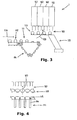
- Fig. 3 shows a side view, seen in the transport direction of the egg chains, of the transfer buffer 111 for receiving rows of eggs from a supply conveyor 112, and a transfer unit 113 for lifting eggs from the transfer buffer into the transfer location 107 above the transfer buffer. The direction of movement is indicated with arrow 123.
- the transfer unit 113 and the transfer buffer 111 are located below the egg chains 102 of the transfer device.
- Fig. 4 shows a view in close up of the transfer buffer seen in the transport direction.
- the transfer buffer receives the eggs from the supply conveyor 112, on which the eggs fro example are supported by rails or rolls.
- the transfer buffer 111 comprises parallel fingers 114 supporting egg supports 115 for movement along the fingers in a supply direction 116. Each egg is supported on two fingers 114 such that the transfer unit 113 can move between the fingers 114 to engage the supported egg from below, while the egg is moved along the fingers 114 in the supply direction 116.
- the fingers 114 comprise endless tracks provided with egg supports 115. The endless tracks move the eggs along the fingers 114 in the supply direction 116. By using endless tracks, the eggs are transported with a continuous speed along the fingers, which reduces the risk of the eggs falling from the egg supports 115.
- solutions known in the art for moving eggs may be provided to transport the eggs along the fingers.
- the transfer unit 113 for lifting eggs from the transfer buffer 111 into the transfer location 107 above the transfer buffer comprises parallel fingers 123 supporting egg supports also.
- the fingers 123 of the transfer unit 113 are designed for cooperation with the fingers 114 of the transfer buffer 111.
- the fingers of the transfer unit can be moved between the fingers of the transfer buffer to pick up the eggs from below. From fig. 4 it is clear that the fingers 123 of the transfer unit 113 are located between the fingers 114 of the transfer buffer 111.
- the transfer unit shown supports the eggs each on one finger. It is observed that in an alternative embodiment, the eggs may be supported by multiple fingers of the transfer unit and/or the transfer buffer respectively, which fingers are positioned such that the fingers of the transfer unit can move between the fingers of the transfer buffer.
- the transfer unit is provided with fingers which move between the rows of eggs presented on the transfer buffer, and engage the eggs from the sides.
- the transfer unit does not engage the eggs from below the egg supports of the transfer buffer.
- the transfer buffer does not need to be provided with fingers.
- the transfer unit 113 is supported by a driven support 122 for movement of the transfer unit along an endless transfer trajectory 117 extending in a vertical plane parallel to the supply direction 116.
- Fig. 5 shows the transfer trajectory 117.
- the transfer unit is moved along the trajectory from a start location 118, in the preferred embodiment shown located below the buffer, via a lift up location 119 between the parallel rows of egg supports into the transfer location 120 and back down into the start location.
- the preferred transfer trajectory 117 shown allows for optimal engaging the eggs from the transfer buffer, and optimally presenting the eggs to the grippers of the egg chains in the transfer location.
- the drive support 122 of the transfer unit 113 is designed such that the direction of movement of the transfer unit in the start location 118 is inverted from a movement essentially contrary to the supply direction 116 to a movement into the supply direction 116.
- the transfer unit is moved into the start position 118 in an essentially horizontal direction, which allows to correctly position the transfer unit 113 below the eggs supported by the transfer buffer 111 in an efficient way.
- the transfer unit is typically moved along a curved trajectory which requires more space to allow the transfer unit to be correctly positioned.
- the drive support 122 of the transfer unit 113 is designed such that the transfer unit is moved along the transfer trajectory such that in the transfer location 119 the transfer unit 113 moves in the supply direction as well as in the upward direction through the transfer buffer 111 for picking up the eggs during transport by the transfer buffer in the supply direction.
- the eggs can be lifted from the transfer buffer while still being transported in the supply direction. This allows for transfer of the eggs with minimal accelerations, and thus minimizes the chance of breakage of the eggs.
- the driven support 122 of the transfer unit 113 is designed such that the direction of movement of the transfer unit 113 in the transfer location 120 of the transfer trajectory is inverted from an essentially upward direction into an essentially downward direction such that an egg is transferred into an essentially vertical direction into a gripper located in the transfer location 107.
- the eggs are moved upward into the downward hanging grippers, without substantial movement in other directions.
- the egg is engaged by the gripper at the moment the movement is inverted from upward to downward at which the vertical speed is zero.
- a movable support frame 105 is provided for supporting a section 106 of the egg chains 103 adjacent a transfer location 107.
- the support frame 105 is supported for movement parallel to the transport direction 104.
- a section 106 of the lower run of the egg chains 102 is looped via a first loop wheel 108a and a second loop wheel 108b over the movably mounted support frame 105 such that a section 106 of the egg chains 102 extends adjacent the transfer location 107.
- the support frame 105 comprises a first guide wheel 109a at one end for receiving the egg chains from the first loop wheel 108a and a second guide wheel 109b at an opposite end for guiding the egg chains towards the second loop wheel 109b. It is observed that in the distance between the guide wheels on the opposite ends of the movable support frame is larger than the distance between the loop wheels such that the egg chains guided by a loop wheel and a guide wheel follows a S-shaped trajectory.
- a drive 110 is provided for moving the support frame 105 parallel to the transport direction 104 such that when the frame 105 is moved contrary to the transport direction, the movement of the section 106 of the egg chains adjacent the transfer location 107 is reduced relative to the transport speed to allow the grippers to pick up eggs provided in the transfer location.
- Fig. 1 shows the transfer device 101 with the movable support frame 105 in a first position
- fig. 2 shows the transfer device with the movable support frame in a second position.
- the drive 110 moves the frame between these positions.
- the frame is moved in a direction opposite to the transport direction, i.e. from the position shown in fig. 1 into the position shown in fig. 2
- the section of the egg chains supported by the frame is moved in a direction opposite the transport direction also.
- the frame 105 the speed relative to the pick up position of the sections of the egg chains 106, extending along the transfer location 107, is reduced.
- the egg chains move along the transfer location with a speed lower than the transport speed, which facilitates engaging eggs presented in the transfer location with the grippers supported by the egg chains.
- the drive is designed to move the support frame contrary to the transport direction with a speed such that the movement of the section of the egg chains adjacent the transfer location is essentially reduced to near stand still, preferably stand still, such that the grippers are essentially stationary relative to the transfer location when engaging the eggs in the transfer location.
- the frame After the eggs are picked up by the grippers, the frame is moved in the transport direction to return to its initial position shown in fig. 1 . This movement of the frame accelerates the egg chains supported by the frame up to a speed higher than the transport speed. Since the eggs are at this moment securely held in the grippers, this chance of breakage of the eggs is minimal.
- the speed of the egg chain is reduced to transport speed.
- the eggs are transported at transport speed, while the speed of the egg chains adjacent the transfer location is reduced to pick up the eggs.
- an egg transfer device With an egg transfer device according to the invention, eggs are transported by egg chains at a transport speed, while the speed of sections of the egg chains can be reduced to facilitate picking up eggs.
- the transfer device provides egg chains which combine optimal transport speed with optimal pick up speed in one transfer device.
- the egg transfer device is designed for receiving a flow of eggs which is provided in a supply direction perpendicular to the transport direction, which allows to pick up high quantities of eggs at the optimal pick up speed and thus to use the egg chains as the high volume transport device they are intended for.
- the egg transfer device shown is furthermore provided with a drop off location 120 along the lower run 103 of the egg chains 102 for dropping off eggs.
- the drop off location 121 is provided downstream of the looped section 106 adjacent the transfer location 107.
- the egg transfer device further comprises an additional movable support frame, similar to the one in the transfer location, for supporting a looped section of the egg chains adjacent the drop off location such that the movement of the section of the egg chains adjacent the drop off location can be temporarily reduced to drop off eggs.
- the movement of the eggs in the horizontal plane is at least reduced relative to the transport speed, preferably the egg is held stationary, such that it can be dropped into stationary receiving means, such as a receptacle or packaging, with more accuracy. Dropping the eggs from stationary grippers highly increase the precision of delivery.
- the receptacle for receiving the eggs can be provided without bringing it up to the transport speed of the egg chains. Thus presenting the receptacle is facilitated.
- the transport speed is often limited to allow for accurate feeding of egg into receptacles.
- the direction of movement of the transfer unit, the transfer buffer, the supply conveyor and optionally the egg chains is inverted to provide an egg transfer device for receiving egg form an egg chain and feeding those eggs to a conveyor. Except for the direction of movement the egg transfer device is similar to the ones described here above.
- Such an egg transfer device thus comprises multiple parallel egg chains provided with grippers for engaging eggs and for carrying the eggs along the lower run of the egg chains at a transport speed in a transport direction.
- the direction of movement of the egg chains is not relevant for the working of the transfer unit and the transfer buffer, especially when the egg chains are slowed down or even stopped in the transfer location.
- the transfer unit for receiving multiple rows of eggs from the egg chains in the transfer location directly below the egg chains is supported by a driven support for moving the transfer unit along an endless transfer trajectory extending in a vertical plane parallel to the supply direction such that the transfer unit can be moved from.
- the trajectory can be similar to the one of the egg transfer device described here above, although the direction of movement is inverted.
- the transfer unit thus lowers the eggs from the transfer location below the egg chains to the transfer buffer, which moves the eggs towards the supply conveyor which in turn moves the eggs in a supply direction with a supply speed away from the egg transfer device, more in particular away form the transfer buffer.
- the driven support is designed such that in the let down location the transfer unit moves in the supply direction, preferably with the supply speed, as well as in the downward direction through the transfer buffer for setting down the eggs on the transfer buffer.
- the transfer buffer subsequently transports the eggs into the supply direction and to the supply conveyor.
- the direction of movement of the transfer unit in the transfer location is inverted from an essentially upward direction into an essentially downward direction such that an egg is received in an essentially vertical direction from a gripper.
- this may also comprise transport chains supporting multiple rows of egg grippers.
- one chain can transport multiple rows of eggs.
- groups of actuators are provided for each row of egg gripper.
- the device according to the invention are also suitable for use with transfer device for transporting other round, fragile articles such as for example fruit or vegetables.
Landscapes
- Engineering & Computer Science (AREA)
- Mechanical Engineering (AREA)
- Wrapping Of Specific Fragile Articles (AREA)
Description
- The invention is related to an egg transfer device comprising multiple parallel egg chains provided with grippers and a method using such a transfer device.
- Egg transfer devices comprising one or more parallel egg chains are known in the prior art. For example
EP 0 588 412 discloses an egg transfer device comprising multiple parallel egg chains supporting egg grippers for holding eggs and transferring the eggs in a transport direction. The eggs are typically supplied via a supply conveyor in a supply direction perpendicular to the transport direction. The eggs are lifted into the egg chains by a transfer unit. The transfer unit follows an endless, oval trajectory extending in a plane parallel to the transport direction. The transfer unit lifts the eggs from a transfer buffer, and accelerates into the transport direction perpendicular to the supply direction to present the eggs to the egg grippers moving in the transport direction. The prior art design requires substantial acceleration of the eggs over a short distance to bring the eggs up to speed with the egg chains, which typically move at high transport speeds to enable a substantial flow through of egg with a minimum number of egg chains. The acceleration increases the risk of the fragile egg braking during the transfer into the egg chains. - The present invention aims to provide an alternative egg transfer device which preferably overcomes, or at least reduce, the above mentioned problems.
- This object is achieved by the invention providing an egg transfer device according to claim 1. The invention furthermore provides a method for using such an egg transfer device according to the invention.
- An egg transfer device according to the invention comprises multiple parallel egg chains provided with grippers for engaging eggs and for carrying the eggs along the lower run of the egg chains, at a transport speed and in a transport direction.
- The egg transfer device is furthermore provided with a transfer buffer for receiving multiple rows of eggs from a supply conveyor. The transfer buffer is located below the egg chains and comprises movable egg supports for supporting eggs while moving them at a supply speed in a supply direction.
- The egg transfer device also comprises a transfer unit for lifting multiple rows of eggs from the transfer buffer into a transfer location above the transfer buffer and directly below the egg chains for feeding the eggs into the grippers. The transfer unit is supported by a driven support for moving the transfer unit along an endless transfer trajectory extending in a vertical plane parallel to the supply direction such that the transfer unit can be moved from a start location, via a lift up location for engaging the eggs, into the transfer location and back down into the start location. The driven support is designed such that in the lift up location the transfer unit moves in the supply direction, preferably with the supply speed, as well as in the upward direction through the transfer buffer for picking up the eggs during transport by the transfer buffer in the supply direction.
- The driven support is furthermore designed such that the direction of movement of the transfer unit in the transfer location is inverted from an essentially upward direction into an essentially downward direction such that an egg is transferred in to an essentially vertical direction into a gripper.
- An egg transfer device comprising a transfer buffer and transfer unit according to the invention is optimally equipped for receiving eggs from a conveyor and feeding them into egg chain supported grippers. The transfer unit is supported by a driven support which is designed such that the transfer unit of the device is moved along a transfer trajectory which allows for optimal engaging the eggs from the transfer buffer, and optimally presenting the eggs to the grippers of the egg chains.
- The driven support is designed such that the transfer unit is moved along the transfer trajectory such that in the lift up location the transfer unit moves in the supply direction as well as in the upward direction through the transfer buffer for picking up the eggs during transport by the transfer buffer in the supply direction. Thus, the eggs can be lifted from the transfer buffer while still being transported in the supply direction. This allows for transfer of the eggs with minimal accelerations, and thus minimizes the chance of breakage of the eggs. The main acceleration is directed upwards such that the eggs are presses securely into the transfer unit. Furthermore, no acceleration is present in a direction perpendicular to the supply direction which contributes to a steady support of the eggs by the transfer unit.
- The driven support is furthermore designed such that the direction of movement of the transfer unit in the transfer location is inverted from an essentially upward direction into an essentially downward direction such that an egg is transferred in to an essentially vertical direction into a gripper. Thus the eggs are moved upward into the downward hanging grippers, without substantial movement in other directions. Preferably, the egg is engaged by the gripper when its movement is inverted from upward to downward, at which moment the vertical speed is zero.
- With an egg transfer device according to the invention, eggs are fed into the egg chains in a direction parallel to the supply direction such that the egg is not accelerated in a direction perpendicular to the supply direction, furthermore, the eggs are in one single movement fed into the egg grippers in a vertical direction, which allows for optimal engagement by the egg grippers which typically hang down from the egg chains.
- Preferably, the start location of the transfer unit trajectory is located below the transfer buffer. In this embodiment the egg transfer buffer is provided with parallel fingers extending in the supply direction, which fingers support the egg supports for movement along the fingers in a supply direction. Furthermore, the egg transfer unit comprises parallel fingers for supporting eggs which fingers are configured for cooperating with the fingers of the transfer buffer such that the fingers of the transfer unit can move between the fingers of the buffer to engage the eggs from below and lift them from the egg supports.
- This configuration of the transfer device facilitates feeding eggs from a transfer conveyor into the egg chains. The fingers on both the transfer unit and the buffer allows for the transfer unit to move its fingers between the fingers of the transfer buffer, and to engage the eggs supported by the transfer buffer from below.
- Preferably, the driven support is designed such that the direction of movement of the transfer unit in the start location is inverted from a movement essentially contrary to the supply direction to a movement into the supply direction. The transfer unit is moved into the start position in an essentially horizontal direction, which allows to correctly position the transfer unit below the transfer buffer in an efficient way, and via a compact space. In prior art devices, the transfer unit is typically moved along a curved trajectory which requires more space to allow the transfer unit to be correctly positioned.
- Preferably, an egg transfer device according to the invention comprises a movable support frame for supporting a looped section of the egg chains adjacent the transfer location, which support frame is supported for movement parallel to the transport direction. A section of the lower run of the egg chains is looped via a first loop wheel and a second loop wheel over the movably mounted support frame such that a section of the egg chains extends adjacent the transfer location. The frame comprises a first guide wheel at one end for receiving the egg chains from the first loop wheel and a second guide wheel at an opposite end for guiding the egg chains towards the second loop wheel. Furthermore, a drive for is provided for moving the support frame parallel to the transport direction such that when the frame is moved contrary to the transport direction the movement of the section of the egg chains adjacent the transfer location is reduced relative to the transport speed such that the eggs supported by the transfer unit can be transferred into the grippers.
- With this embodiment, a section of the egg chains can be slowed down to allow the grippers to engage the eggs while moving at a speed lower than the transport speed. The egg transfer device thus facilitates engagement of the eggs by the grippers. Preferably, the egg transfer device is provided with a drive which moves the support frame contrary to the transport direction with such a speed that the movement of the section of the egg chains adjacent the transfer location is essentially stopped, and the grippers are essentially stationary in the transfer location when engaging the eggs. Thus, the eggs can be fed in an essentially vertical direction into stationary grippers, which facilitates engaging the eggs by the grippers.
- It is observed that with an egg transfer device according to the invention only a section of the egg chains is movably supported. The main part of the egg chains can be supported by fixed frames and driven by a fixed drive. Since the movable support frame only supports a section of egg chains, it can be small and light compared to the support frame supporting the egg chains, which in turn facilitates quick and iterative movement of the support frame.
- Furthermore, with an egg transfer device according to the invention, the speed of only a section of the egg chains is reduced. The main part of the egg chains moves at transport speed while the section is slowed down for picking up eggs. The transfer device thus allows for transferring already picked up eggs at transport speed while new eggs are fed into the egg chain. Thus, the transport and the processing of the picked up eggs, for example providing the eggs to a packing device of presenting the eggs to optical scanning devices, downstream of the transfer location is not hindered and no time is lost.
- By providing a transfer buffer and transfer unit for presenting the egg to the egg chains in an essentially vertical direction, in combination with a movable support frame which allows to slow down the egg chains, the egg transfer unit is optimally equipped for receiving eggs form a conveyor, in particular a conveyor which provides eggs in a supply direction perpendicular to the egg transport direction.
- Providing the eggs in a supply direction perpendicular to the transport direction is preferred since it allows for changing the product flow from a low speed large width supply flow into a high speed small width transfer flow. For example, the egg supply conveyor, typically a slow speed transport device, provides a flow of eggs constituted by eight parallel rows of eggs, the rows extending in the supply direction. By lifting the eggs into for example four parallel egg chains, which are typical high speed transport devices, the flow is transferred into a narrow flow of eggs, which is four rows wide instead of eight. In a further exemplary embodiment, the eggs are provided in eight parallel flows and transferred into four parallel egg chains.
- In a further embodiment of an egg transfer device according to the invention, a drop off location for dropping off eggs is provided along the lower run of the egg chains, downstream of the looped section and the transfer location. Preferably, the egg transfer embodiment further comprises an additional movable support frame, similar to the one described above, for supporting a looped section of the egg chains adjacent the drop off location such that the movement of the section of the egg chains adjacent the drop off location can be temporarily reduced to drop off eggs. Thus, the movement of the eggs in the horizontal plane is at least reduced relative to the transport speed, preferably the egg is held stationary, such that it can be dropped into stationary receiving means, such as a receptacle or packaging, with more accuracy. Dropping the eggs from stationary grippers highly increase the precision of delivery. Furthermore, the receptacle for receiving the eggs can be provided without bringing it up to the transport speed of the egg chains. Thus presenting the receptacle is facilitated. In the prior art, the transport speed is often limited to allow for accurate feeding of egg into receptacles.
- The invention furthermore provides a method for transferring eggs from a transfer location to a drop off location using an egg transfer device as described above.
- It will be appreciated that the invention can advantageously be integrated in an egg transfer device comprising:
- an egg conveyor with two or more parallel egg chains movable in a transport direction, each egg chain supporting a plurality of egg grippers each adapted to support an egg, which grippers can individually be actuated from a closed position, for supporting an egg, into an open position, for releasing an egg, the egg conveyor further comprising an egg chain conveyor drive for driving the egg chains at a transport speed;
- an egg receiving unit with a receiving area for receiving eggs released by the egg grippers which receiving area is defined by at least one brush wheel rotatable about an axle parallel to the transport direction of the egg chains and which is located below the egg conveyor such that the vertical distance between one egg chain and the receiving area is larger than the vertical distance between another egg chain and the receiving area; and
- an egg chain gripper actuating device comprising:
- one group of one or more actuators for each egg chain, which actuators are designed for selectively actuating passing egg grippers into an open position to release an egg such that the released egg follows a parabolic trajectory from a release spot at which it is released by the gripper to a contact spot at which it contacts the receiving area;
- multiple support frames, each supporting one or more groups of actuators, of which at least one frame is adjustable parallel to the transport direction and relative to another frame, such that the position of the actuators of the one or more groups supported by the frame can be adjusted relative to the position of the one of more actuators of the one or more groups supported by the other frame.
- Further objects, embodiments and elaborations of the apparatus and the methods according to the invention will be apparent from the following description, in which the invention is further illustrated and elucidated on the basis of a number of exemplary embodiments, with reference to the drawings, in which:
-
Fig. 1 shows a simplified side view perpendicular to the transport direction of an egg transfer device according to the invention in a first position; -
Fig. 2 shows a simplified side view perpendicular to the transport direction of the egg transfer device offig. 1 in a second position; -
Fig. 3 shows a side view parallel to the transport direction of an egg transfer device according to the invention comprising a transfer buffer and a transfer unit; -
Fig. 4 shows a side view perpendicular to the transport direction, in close up, of the egg transfer device offig. 3 ; and -
Fig. 5 shows a trajectory of the transfer unit offig. 3 . - Now referring to
figures 1-5 the present invention will be illustrated. -
Fig. 1 shows anegg transfer device 101 according to the invention. Theegg transfer device 101 comprises fouregg chains 102, of which only one shows in this particular side view. It is observed that in alternative embodiments, the device can be provided with less or more egg chains, preferably two or more. It is furthermore observed that, in an embodiment in which the egg chains extend perpendicular to the supply conveyor, the number of egg chains is equal to the number of rows lifted by the transfer unit. - The more rows the transfer unit lifts in one turn, the more time there is to return the transfer unit back into the lift up position, which allows for a more stable movement and a low power drive for moving the driven support.
- The egg chains are provided with grippers (not shown), hanging down from the egg chains, for engaging eggs and for carrying the eggs along the lower run 103 of the egg chains. The eggs are transported at a transport speed and in a transport direction, which is indicated with
arrow 104. - The transfer device comprises a
transfer buffer 111 and atransfer unit 113 to feed the eggs supplied by asupply conveyor 112 to the grippers of theegg chains 102.Fig. 3 shows a side view, seen in the transport direction of the egg chains, of thetransfer buffer 111 for receiving rows of eggs from asupply conveyor 112, and atransfer unit 113 for lifting eggs from the transfer buffer into thetransfer location 107 above the transfer buffer. The direction of movement is indicated witharrow 123. Thetransfer unit 113 and thetransfer buffer 111 are located below theegg chains 102 of the transfer device. -
Fig. 4 shows a view in close up of the transfer buffer seen in the transport direction. The transfer buffer receives the eggs from thesupply conveyor 112, on which the eggs fro example are supported by rails or rolls. Thetransfer buffer 111 comprisesparallel fingers 114 supporting egg supports 115 for movement along the fingers in asupply direction 116. Each egg is supported on twofingers 114 such that thetransfer unit 113 can move between thefingers 114 to engage the supported egg from below, while the egg is moved along thefingers 114 in thesupply direction 116. In the particular embodiment shown, thefingers 114 comprise endless tracks provided with egg supports 115. The endless tracks move the eggs along thefingers 114 in thesupply direction 116. By using endless tracks, the eggs are transported with a continuous speed along the fingers, which reduces the risk of the eggs falling from the egg supports 115. - In an alternative embodiment, solutions known in the art for moving eggs may be provided to transport the eggs along the fingers.
- The
transfer unit 113 for lifting eggs from thetransfer buffer 111 into thetransfer location 107 above the transfer buffer comprisesparallel fingers 123 supporting egg supports also. Thefingers 123 of thetransfer unit 113 are designed for cooperation with thefingers 114 of thetransfer buffer 111. The fingers of the transfer unit can be moved between the fingers of the transfer buffer to pick up the eggs from below. Fromfig. 4 it is clear that thefingers 123 of thetransfer unit 113 are located between thefingers 114 of thetransfer buffer 111. The transfer unit shown supports the eggs each on one finger. It is observed that in an alternative embodiment, the eggs may be supported by multiple fingers of the transfer unit and/or the transfer buffer respectively, which fingers are positioned such that the fingers of the transfer unit can move between the fingers of the transfer buffer. - In a further preferred embodiment, the transfer unit is provided with fingers which move between the rows of eggs presented on the transfer buffer, and engage the eggs from the sides. In such an embodiment the transfer unit does not engage the eggs from below the egg supports of the transfer buffer. Thus, in this embodiment the transfer buffer does not need to be provided with fingers.
- In a transfer device according the invention, the
transfer unit 113 is supported by a drivensupport 122 for movement of the transfer unit along an endless transfer trajectory 117 extending in a vertical plane parallel to thesupply direction 116.Fig. 5 shows the transfer trajectory 117. The transfer unit is moved along the trajectory from astart location 118, in the preferred embodiment shown located below the buffer, via a lift uplocation 119 between the parallel rows of egg supports into thetransfer location 120 and back down into the start location. The preferred transfer trajectory 117 shown allows for optimal engaging the eggs from the transfer buffer, and optimally presenting the eggs to the grippers of the egg chains in the transfer location. - The
drive support 122 of thetransfer unit 113 is designed such that the direction of movement of the transfer unit in thestart location 118 is inverted from a movement essentially contrary to thesupply direction 116 to a movement into thesupply direction 116. The transfer unit is moved into thestart position 118 in an essentially horizontal direction, which allows to correctly position thetransfer unit 113 below the eggs supported by thetransfer buffer 111 in an efficient way. In prior art devices, the transfer unit is typically moved along a curved trajectory which requires more space to allow the transfer unit to be correctly positioned. - Furthermore, the
drive support 122 of thetransfer unit 113 is designed such that the transfer unit is moved along the transfer trajectory such that in thetransfer location 119 thetransfer unit 113 moves in the supply direction as well as in the upward direction through thetransfer buffer 111 for picking up the eggs during transport by the transfer buffer in the supply direction. Thus, the eggs can be lifted from the transfer buffer while still being transported in the supply direction. This allows for transfer of the eggs with minimal accelerations, and thus minimizes the chance of breakage of the eggs. - Furthermore, the driven
support 122 of thetransfer unit 113 is designed such that the direction of movement of thetransfer unit 113 in thetransfer location 120 of the transfer trajectory is inverted from an essentially upward direction into an essentially downward direction such that an egg is transferred into an essentially vertical direction into a gripper located in thetransfer location 107. Thus the eggs are moved upward into the downward hanging grippers, without substantial movement in other directions. Preferably, the egg is engaged by the gripper at the moment the movement is inverted from upward to downward at which the vertical speed is zero. - It is observed that given the trajectory shown in
fig. 5 , it lies within the general knowledge of the skilled person to design a driven support for movement of the transfer unit along that trajectory. It is furthermore observed that a transfer unit moved along an alternative, less optimal, trajectory can also be used for feeding the eggs into the pick up position. - In the particular embodiment shown, a
movable support frame 105 is provided for supporting asection 106 of the egg chains 103 adjacent atransfer location 107. Thesupport frame 105 is supported for movement parallel to thetransport direction 104. - A
section 106 of the lower run of theegg chains 102 is looped via afirst loop wheel 108a and asecond loop wheel 108b over the movably mountedsupport frame 105 such that asection 106 of theegg chains 102 extends adjacent thetransfer location 107. - The
support frame 105 comprises afirst guide wheel 109a at one end for receiving the egg chains from thefirst loop wheel 108a and a second guide wheel 109b at an opposite end for guiding the egg chains towards the second loop wheel 109b. It is observed that in the distance between the guide wheels on the opposite ends of the movable support frame is larger than the distance between the loop wheels such that the egg chains guided by a loop wheel and a guide wheel follows a S-shaped trajectory. - A
drive 110 is provided for moving thesupport frame 105 parallel to thetransport direction 104 such that when theframe 105 is moved contrary to the transport direction, the movement of thesection 106 of the egg chains adjacent thetransfer location 107 is reduced relative to the transport speed to allow the grippers to pick up eggs provided in the transfer location. -
Fig. 1 shows thetransfer device 101 with themovable support frame 105 in a first position, andfig. 2 shows the transfer device with the movable support frame in a second position. Thedrive 110 moves the frame between these positions. When the frame is moved in a direction opposite to the transport direction, i.e. from the position shown infig. 1 into the position shown infig. 2 , the section of the egg chains supported by the frame is moved in a direction opposite the transport direction also. By this movement of theframe 105, the speed relative to the pick up position of the sections of theegg chains 106, extending along thetransfer location 107, is reduced. Thus the egg chains move along the transfer location with a speed lower than the transport speed, which facilitates engaging eggs presented in the transfer location with the grippers supported by the egg chains. - Preferably, the drive is designed to move the support frame contrary to the transport direction with a speed such that the movement of the section of the egg chains adjacent the transfer location is essentially reduced to near stand still, preferably stand still, such that the grippers are essentially stationary relative to the transfer location when engaging the eggs in the transfer location.
- After the eggs are picked up by the grippers, the frame is moved in the transport direction to return to its initial position shown in
fig. 1 . This movement of the frame accelerates the egg chains supported by the frame up to a speed higher than the transport speed. Since the eggs are at this moment securely held in the grippers, this chance of breakage of the eggs is minimal. When the section of the egg chains has passed the guide wheel guiding the egg chain towards the second loop wheel, the speed of the egg chain is reduced to transport speed. Thus, outside the looped section, the eggs are transported at transport speed, while the speed of the egg chains adjacent the transfer location is reduced to pick up the eggs. - With an egg transfer device according to the invention, eggs are transported by egg chains at a transport speed, while the speed of sections of the egg chains can be reduced to facilitate picking up eggs. Thus the transfer device provides egg chains which combine optimal transport speed with optimal pick up speed in one transfer device. Preferably, the egg transfer device is designed for receiving a flow of eggs which is provided in a supply direction perpendicular to the transport direction, which allows to pick up high quantities of eggs at the optimal pick up speed and thus to use the egg chains as the high volume transport device they are intended for.
- The egg transfer device shown is furthermore provided with a drop off
location 120 along the lower run 103 of theegg chains 102 for dropping off eggs. The drop off location 121 is provided downstream of the loopedsection 106 adjacent thetransfer location 107. - In a further embodiment, the egg transfer device further comprises an additional movable support frame, similar to the one in the transfer location, for supporting a looped section of the egg chains adjacent the drop off location such that the movement of the section of the egg chains adjacent the drop off location can be temporarily reduced to drop off eggs. Thus, the movement of the eggs in the horizontal plane is at least reduced relative to the transport speed, preferably the egg is held stationary, such that it can be dropped into stationary receiving means, such as a receptacle or packaging, with more accuracy. Dropping the eggs from stationary grippers highly increase the precision of delivery. Furthermore, the receptacle for receiving the eggs can be provided without bringing it up to the transport speed of the egg chains. Thus presenting the receptacle is facilitated. In the prior art, the transport speed is often limited to allow for accurate feeding of egg into receptacles.
- In a further embodiment according to the invention, the direction of movement of the transfer unit, the transfer buffer, the supply conveyor and optionally the egg chains is inverted to provide an egg transfer device for receiving egg form an egg chain and feeding those eggs to a conveyor. Except for the direction of movement the egg transfer device is similar to the ones described here above.
- Such an egg transfer device thus comprises multiple parallel egg chains provided with grippers for engaging eggs and for carrying the eggs along the lower run of the egg chains at a transport speed in a transport direction. The direction of movement of the egg chains is not relevant for the working of the transfer unit and the transfer buffer, especially when the egg chains are slowed down or even stopped in the transfer location.
- The transfer unit for receiving multiple rows of eggs from the egg chains in the transfer location directly below the egg chains is supported by a driven support for moving the transfer unit along an endless transfer trajectory extending in a vertical plane parallel to the supply direction such that the transfer unit can be moved from. The trajectory can be similar to the one of the egg transfer device described here above, although the direction of movement is inverted.
- The transfer unit thus lowers the eggs from the transfer location below the egg chains to the transfer buffer, which moves the eggs towards the supply conveyor which in turn moves the eggs in a supply direction with a supply speed away from the egg transfer device, more in particular away form the transfer buffer.
- Since the direction of movement along the transfer trajectory is inverted it is local to rename the "lift up" location as "let down" location and the "start positon" as "end position". Thus the transfer unit moves form the transfer location, via the let down location for releasing the eggs, into the end location and back up into the transfer location. The driven support is designed such that in the let down location the transfer unit moves in the supply direction, preferably with the supply speed, as well as in the downward direction through the transfer buffer for setting down the eggs on the transfer buffer. The transfer buffer subsequently transports the eggs into the supply direction and to the supply conveyor.
- The direction of movement of the transfer unit in the transfer location is inverted from an essentially upward direction into an essentially downward direction such that an egg is received in an essentially vertical direction from a gripper.
- It is observed that when the text refers to egg chains, this may also comprise transport chains supporting multiple rows of egg grippers. Thus, one chain can transport multiple rows of eggs. In such an embodiment groups of actuators are provided for each row of egg gripper.
- It is furthermore observed that the device according to the invention are also suitable for use with transfer device for transporting other round, fragile articles such as for example fruit or vegetables.
Claims (4)
- Egg transfer device (101) comprising:- multiple parallel egg chains (102) provided with grippers for engaging eggs and for carrying the eggs along the lower run of the egg chains at a transport speed in a transport direction (104);- a transfer buffer (111) for receiving multiple rows of eggs from a supply conveyor (112), which transfer buffer is located below the egg chains and comprises movable egg supports for supporting eggs while moving them at a supply speed in a supply direction (116); and- a transfer unit (113) for lifting multiple rows of eggs from the transfer buffer into a transfer location (107) above the transfer buffer and directly below the egg chains for feeding the eggs into the grippers, and which transfer unit is supported by a driven support (112) for moving the transfer unit along an endless transfer trajectory extending in a vertical plane parallel to the supply direction such that the transfer unit can be moved from a start location (118), via a lift up location (119) for engaging the eggs, into the transfer location (107) and back down into the start location, characterized in that the driven support (112) is designed such that in the lift up location (119) the transfer unit (113) moves in the supply direction (116), preferably with the supply speed, as well as in the upward direction through the transfer buffer (111) for picking up the eggs during transport by the transfer buffer in the supply direction (116), and the direction of movement of the transfer unit (113) in the transfer location (107) is inverted from an essentially upward direction into an essentially downward direction such that an egg is transferred in to an essentially vertical direction into a gripper.
- Egg transfer device according to claim 1, wherein the start location of the transfer unit trajectory is located below the transfer buffer, and the egg transfer buffer is provided with parallel fingers extending in the transport direction, which fingers support the egg supports for movement along the fingers in a supply direction, and the egg transfer unit comprises parallel fingers for supporting eggs which fingers are configured for cooperating with the fingers of the transfer buffer such that the fingers of the transfer unit can move between the fingers of the buffer to engage the eggs from below and lift them from the egg supports.
- Egg transfer device according to claim 1 or 2, further comprising:- a movable support frame for supporting a looped section of the egg chains adjacent the transfer location, which support frame is supported for movement parallel to the transport direction;
wherein a section of the lower run of the egg chains is looped via a first loop wheel and a second loop wheel over the movably mounted support frame such that a section of the egg chains extends adjacent the transfer location;
which frame comprises a first guide wheel at one end for receiving the egg chains from the first loop wheel and a second guide wheel at an opposite end for guiding the egg chains towards the second loop wheel; and- a drive for moving the support frame parallel to the transport direction such that when the frame is moved contrary to the transport direction the movement of the section of the egg chains adjacent the transfer location is reduced relative to the transport speed such that the eggs supported by the transfer unit can be transferred into the grippers. - Egg transfer device according to claim 3, wherein the drive is designed to move the support frame contrary to the transport direction with a speed such that the movement of the section of the egg chains adjacent the transfer location is essentially stopped, for essentially stationary positioning the grippers engaging the eggs in the transfer location.
Applications Claiming Priority (1)
| Application Number | Priority Date | Filing Date | Title |
|---|---|---|---|
| PCT/NL2010/050548 WO2012030207A1 (en) | 2010-09-01 | 2010-09-01 | Egg chain gripper actuating device and egg transfer device. |
Publications (2)
| Publication Number | Publication Date |
|---|---|
| EP2611693A1 EP2611693A1 (en) | 2013-07-10 |
| EP2611693B1 true EP2611693B1 (en) | 2014-11-26 |
Family
ID=44065145
Family Applications (1)
| Application Number | Title | Priority Date | Filing Date |
|---|---|---|---|
| EP10755253.1A Active EP2611693B1 (en) | 2010-09-01 | 2010-09-01 | Egg transfer device |
Country Status (3)
| Country | Link |
|---|---|
| US (2) | US9038812B2 (en) |
| EP (1) | EP2611693B1 (en) |
| WO (1) | WO2012030207A1 (en) |
Families Citing this family (7)
| Publication number | Priority date | Publication date | Assignee | Title |
|---|---|---|---|---|
| WO2012030207A1 (en) * | 2010-09-01 | 2012-03-08 | Staalkat International B.V. | Egg chain gripper actuating device and egg transfer device. |
| NL2014158B1 (en) * | 2015-01-19 | 2017-01-05 | Sanovo Technology Netherlands Bv | Egg transfer device. |
| BR112017015286B1 (en) * | 2015-01-19 | 2021-07-13 | Sanovo Technology Netherlands B.V. | SYSTEM, DEVICE AND METHOD FOR PRINTING ON EGGS |
| US11178854B2 (en) | 2019-01-10 | 2021-11-23 | Moba Group B.V. | Vertical egg washer and dryer such as integrated into an egg processing line |
| CN110194369B (en) * | 2019-07-02 | 2024-02-02 | 江苏宏盛景智能装备有限公司 | Automatic egg detecting intelligent device |
| CN113443342B (en) * | 2021-07-02 | 2023-05-23 | 长春新希望饲料有限公司 | Egg conveying line capable of being flexibly bent |
| CN116424778A (en) * | 2023-03-30 | 2023-07-14 | 宁波润德机械制造有限公司 | A dual-channel pressure-free conveying system |
Family Cites Families (17)
| Publication number | Priority date | Publication date | Assignee | Title |
|---|---|---|---|---|
| US3034626A (en) * | 1961-02-14 | 1962-05-15 | Lamb Co F Jos | Brush controlled gravity feeds |
| NL6717724A (en) | 1967-12-28 | 1969-07-01 | ||
| US4776465A (en) * | 1982-07-01 | 1988-10-11 | Diamond Automations, Inc. | Egg processing system |
| US4505373A (en) * | 1982-07-01 | 1985-03-19 | Diamond Automations, Inc. | Egg transfer system |
| US4519494A (en) * | 1982-07-01 | 1985-05-28 | Diamond Automations, Inc. | Egg handling system |
| US4487321A (en) * | 1982-07-01 | 1984-12-11 | Diamond Automations, Inc. | Article coding and separating system |
| US4519505A (en) * | 1982-07-01 | 1985-05-28 | Diamond Automations, Inc. | Egg transfer system |
| US4488637A (en) * | 1982-07-01 | 1984-12-18 | Diamond Automations, Inc. | Egg carrier |
| US5232080A (en) | 1989-03-10 | 1993-08-03 | Fps Food Processing Systems B.V. | Article handling method and apparatus |
| NL9001682A (en) * | 1990-07-24 | 1992-02-17 | Staalkat Bv | CARRIER FOR ARTICLES SUCH AS EGGS AND TRANSPORTATION DEVICES EQUIPPED WITH SUCH CARRIER. |
| US5168977A (en) * | 1991-06-05 | 1992-12-08 | Fps Food Processing Systems B.V. | Release mechanism |
| US5167317A (en) * | 1991-06-05 | 1992-12-01 | Fps Food Processing Systems B.V. | Apparatus for and method of transferring articles such as eggs |
| NL9201530A (en) | 1992-09-02 | 1994-04-05 | Food Processing Systems | Device for transferring substantially spherical or ellipsoidal products, such as, for example, eggs, fruit or vegetables. |
| NL1004779C2 (en) * | 1996-12-13 | 1998-06-17 | Food Processing Systems | Device for transferring individual products, such as eggs and fruit, from a supply conveyor to a packaging device. |
| US6029424A (en) | 1998-01-16 | 2000-02-29 | Diamond Automations, Inc. | High-speed egg processing system and method |
| US8387775B2 (en) * | 2008-09-05 | 2013-03-05 | Diamond Automations, Inc. | Egg handling system |
| WO2012030207A1 (en) * | 2010-09-01 | 2012-03-08 | Staalkat International B.V. | Egg chain gripper actuating device and egg transfer device. |
-
2010
- 2010-09-01 WO PCT/NL2010/050548 patent/WO2012030207A1/en not_active Ceased
- 2010-09-01 US US13/819,706 patent/US9038812B2/en active Active
- 2010-09-01 EP EP10755253.1A patent/EP2611693B1/en active Active
-
2015
- 2015-05-08 US US14/708,008 patent/US9434556B2/en active Active
Also Published As
| Publication number | Publication date |
|---|---|
| US20150239681A1 (en) | 2015-08-27 |
| EP2611693A1 (en) | 2013-07-10 |
| WO2012030207A1 (en) | 2012-03-08 |
| US9434556B2 (en) | 2016-09-06 |
| US9038812B2 (en) | 2015-05-26 |
| US20130199895A1 (en) | 2013-08-08 |
Similar Documents
| Publication | Publication Date | Title |
|---|---|---|
| EP0449386B1 (en) | A method of and apparatus for sorting and bundling flowers | |
| CN104271477B (en) | For by the equipment of one group of pallet sequentially feeding to the sealer of described pallet in the case of applying coverlay | |
| US9434556B2 (en) | Egg chain gripper actuating device and egg transfer device | |
| EP1971541B1 (en) | Method and a system for transferring of items | |
| US9199795B2 (en) | Apparatus and method of egg transfer within an egg handling machine | |
| US9132970B2 (en) | Method for grouping products together with a view to case packing same | |
| CA2650249A1 (en) | Packaging system having loading carousel | |
| WO2018172376A1 (en) | Mushroom handling apparatus | |
| US6220424B1 (en) | Method and apparatus for transferring items from a conveyor | |
| US12448224B2 (en) | Conveyor transfer system | |
| CN107406155A (en) | Egg transfer device | |
| GB2595926A (en) | Mushroom handling apparatus | |
| US6758322B2 (en) | Method and device for transferring blister packs and the like from a cutting station to a feeding line of a packaging machine | |
| US9856043B2 (en) | Method and device for handling bags combined into bundles | |
| JP2010035523A (en) | Carrier for mushroom cultivation bottle, and screening device for mushroom | |
| JP2858854B2 (en) | Article arrangement changing mechanism and box packing apparatus using the same | |
| EP2377763B1 (en) | Apparatus and method for turning eggs | |
| JPH06227650A (en) | Transfer device for spherical or ellipse article | |
| EP3849389B1 (en) | Device for breaking eggs | |
| JP2006248748A (en) | Conveying material distribution structure of conveying device | |
| EP1247770B1 (en) | Apparatus for transferring fruit products from one conveyor to another conveyor arranged at right angles to the first one | |
| JP2000128352A (en) | Article transfer device | |
| JP2003235349A (en) | Method of harvest for cultured mushroom and equipment for the same | |
| JP2000247410A (en) | Method and device for conveying article of cargo handling facility |
Legal Events
| Date | Code | Title | Description |
|---|---|---|---|
| PUAI | Public reference made under article 153(3) epc to a published international application that has entered the european phase |
Free format text: ORIGINAL CODE: 0009012 |
|
| 17P | Request for examination filed |
Effective date: 20130308 |
|
| AK | Designated contracting states |
Kind code of ref document: A1 Designated state(s): AL AT BE BG CH CY CZ DE DK EE ES FI FR GB GR HR HU IE IS IT LI LT LU LV MC MK MT NL NO PL PT RO SE SI SK SM TR |
|
| DAX | Request for extension of the european patent (deleted) | ||
| 17Q | First examination report despatched |
Effective date: 20131209 |
|
| GRAP | Despatch of communication of intention to grant a patent |
Free format text: ORIGINAL CODE: EPIDOSNIGR1 |
|
| INTG | Intention to grant announced |
Effective date: 20140821 |
|
| RAP1 | Party data changed (applicant data changed or rights of an application transferred) |
Owner name: SANOVO TECHNOLOGY NETHERLANDS B.V. |
|
| GRAS | Grant fee paid |
Free format text: ORIGINAL CODE: EPIDOSNIGR3 |
|
| GRAA | (expected) grant |
Free format text: ORIGINAL CODE: 0009210 |
|
| AK | Designated contracting states |
Kind code of ref document: B1 Designated state(s): AL AT BE BG CH CY CZ DE DK EE ES FI FR GB GR HR HU IE IS IT LI LT LU LV MC MK MT NL NO PL PT RO SE SI SK SM TR |
|
| REG | Reference to a national code |
Ref country code: GB Ref legal event code: FG4D |
|
| REG | Reference to a national code |
Ref country code: CH Ref legal event code: EP |
|
| REG | Reference to a national code |
Ref country code: AT Ref legal event code: REF Ref document number: 698008 Country of ref document: AT Kind code of ref document: T Effective date: 20141215 |
|
| REG | Reference to a national code |
Ref country code: IE Ref legal event code: FG4D |
|
| REG | Reference to a national code |
Ref country code: DE Ref legal event code: R096 Ref document number: 602010020556 Country of ref document: DE Effective date: 20150108 |
|
| REG | Reference to a national code |
Ref country code: NL Ref legal event code: T3 |
|
| REG | Reference to a national code |
Ref country code: AT Ref legal event code: MK05 Ref document number: 698008 Country of ref document: AT Kind code of ref document: T Effective date: 20141126 |
|
| REG | Reference to a national code |
Ref country code: LT Ref legal event code: MG4D |
|
| PG25 | Lapsed in a contracting state [announced via postgrant information from national office to epo] |
Ref country code: LT Free format text: LAPSE BECAUSE OF FAILURE TO SUBMIT A TRANSLATION OF THE DESCRIPTION OR TO PAY THE FEE WITHIN THE PRESCRIBED TIME-LIMIT Effective date: 20141126 Ref country code: FI Free format text: LAPSE BECAUSE OF FAILURE TO SUBMIT A TRANSLATION OF THE DESCRIPTION OR TO PAY THE FEE WITHIN THE PRESCRIBED TIME-LIMIT Effective date: 20141126 Ref country code: ES Free format text: LAPSE BECAUSE OF FAILURE TO SUBMIT A TRANSLATION OF THE DESCRIPTION OR TO PAY THE FEE WITHIN THE PRESCRIBED TIME-LIMIT Effective date: 20141126 Ref country code: NO Free format text: LAPSE BECAUSE OF FAILURE TO SUBMIT A TRANSLATION OF THE DESCRIPTION OR TO PAY THE FEE WITHIN THE PRESCRIBED TIME-LIMIT Effective date: 20150226 Ref country code: PT Free format text: LAPSE BECAUSE OF FAILURE TO SUBMIT A TRANSLATION OF THE DESCRIPTION OR TO PAY THE FEE WITHIN THE PRESCRIBED TIME-LIMIT Effective date: 20150326 Ref country code: IS Free format text: LAPSE BECAUSE OF FAILURE TO SUBMIT A TRANSLATION OF THE DESCRIPTION OR TO PAY THE FEE WITHIN THE PRESCRIBED TIME-LIMIT Effective date: 20150326 |
|
| PG25 | Lapsed in a contracting state [announced via postgrant information from national office to epo] |
Ref country code: HR Free format text: LAPSE BECAUSE OF FAILURE TO SUBMIT A TRANSLATION OF THE DESCRIPTION OR TO PAY THE FEE WITHIN THE PRESCRIBED TIME-LIMIT Effective date: 20141126 Ref country code: GR Free format text: LAPSE BECAUSE OF FAILURE TO SUBMIT A TRANSLATION OF THE DESCRIPTION OR TO PAY THE FEE WITHIN THE PRESCRIBED TIME-LIMIT Effective date: 20150227 Ref country code: SE Free format text: LAPSE BECAUSE OF FAILURE TO SUBMIT A TRANSLATION OF THE DESCRIPTION OR TO PAY THE FEE WITHIN THE PRESCRIBED TIME-LIMIT Effective date: 20141126 Ref country code: LV Free format text: LAPSE BECAUSE OF FAILURE TO SUBMIT A TRANSLATION OF THE DESCRIPTION OR TO PAY THE FEE WITHIN THE PRESCRIBED TIME-LIMIT Effective date: 20141126 Ref country code: AT Free format text: LAPSE BECAUSE OF FAILURE TO SUBMIT A TRANSLATION OF THE DESCRIPTION OR TO PAY THE FEE WITHIN THE PRESCRIBED TIME-LIMIT Effective date: 20141126 Ref country code: CY Free format text: LAPSE BECAUSE OF FAILURE TO SUBMIT A TRANSLATION OF THE DESCRIPTION OR TO PAY THE FEE WITHIN THE PRESCRIBED TIME-LIMIT Effective date: 20141126 |
|
| PG25 | Lapsed in a contracting state [announced via postgrant information from national office to epo] |
Ref country code: DK Free format text: LAPSE BECAUSE OF FAILURE TO SUBMIT A TRANSLATION OF THE DESCRIPTION OR TO PAY THE FEE WITHIN THE PRESCRIBED TIME-LIMIT Effective date: 20141126 Ref country code: EE Free format text: LAPSE BECAUSE OF FAILURE TO SUBMIT A TRANSLATION OF THE DESCRIPTION OR TO PAY THE FEE WITHIN THE PRESCRIBED TIME-LIMIT Effective date: 20141126 Ref country code: RO Free format text: LAPSE BECAUSE OF FAILURE TO SUBMIT A TRANSLATION OF THE DESCRIPTION OR TO PAY THE FEE WITHIN THE PRESCRIBED TIME-LIMIT Effective date: 20141126 Ref country code: SK Free format text: LAPSE BECAUSE OF FAILURE TO SUBMIT A TRANSLATION OF THE DESCRIPTION OR TO PAY THE FEE WITHIN THE PRESCRIBED TIME-LIMIT Effective date: 20141126 Ref country code: CZ Free format text: LAPSE BECAUSE OF FAILURE TO SUBMIT A TRANSLATION OF THE DESCRIPTION OR TO PAY THE FEE WITHIN THE PRESCRIBED TIME-LIMIT Effective date: 20141126 |
|
| REG | Reference to a national code |
Ref country code: DE Ref legal event code: R097 Ref document number: 602010020556 Country of ref document: DE |
|
| PG25 | Lapsed in a contracting state [announced via postgrant information from national office to epo] |
Ref country code: PL Free format text: LAPSE BECAUSE OF FAILURE TO SUBMIT A TRANSLATION OF THE DESCRIPTION OR TO PAY THE FEE WITHIN THE PRESCRIBED TIME-LIMIT Effective date: 20141126 |
|
| PLBE | No opposition filed within time limit |
Free format text: ORIGINAL CODE: 0009261 |
|
| STAA | Information on the status of an ep patent application or granted ep patent |
Free format text: STATUS: NO OPPOSITION FILED WITHIN TIME LIMIT |
|
| 26N | No opposition filed |
Effective date: 20150827 |
|
| PG25 | Lapsed in a contracting state [announced via postgrant information from national office to epo] |
Ref country code: SI Free format text: LAPSE BECAUSE OF FAILURE TO SUBMIT A TRANSLATION OF THE DESCRIPTION OR TO PAY THE FEE WITHIN THE PRESCRIBED TIME-LIMIT Effective date: 20141126 |
|
| PG25 | Lapsed in a contracting state [announced via postgrant information from national office to epo] |
Ref country code: MC Free format text: LAPSE BECAUSE OF FAILURE TO SUBMIT A TRANSLATION OF THE DESCRIPTION OR TO PAY THE FEE WITHIN THE PRESCRIBED TIME-LIMIT Effective date: 20141126 Ref country code: LU Free format text: LAPSE BECAUSE OF FAILURE TO SUBMIT A TRANSLATION OF THE DESCRIPTION OR TO PAY THE FEE WITHIN THE PRESCRIBED TIME-LIMIT Effective date: 20150901 |
|
| REG | Reference to a national code |
Ref country code: CH Ref legal event code: PL |
|
| GBPC | Gb: european patent ceased through non-payment of renewal fee |
Effective date: 20150901 |
|
| REG | Reference to a national code |
Ref country code: IE Ref legal event code: MM4A |
|
| REG | Reference to a national code |
Ref country code: FR Ref legal event code: ST Effective date: 20160531 |
|
| PG25 | Lapsed in a contracting state [announced via postgrant information from national office to epo] |
Ref country code: LI Free format text: LAPSE BECAUSE OF NON-PAYMENT OF DUE FEES Effective date: 20150930 Ref country code: CH Free format text: LAPSE BECAUSE OF NON-PAYMENT OF DUE FEES Effective date: 20150930 Ref country code: GB Free format text: LAPSE BECAUSE OF NON-PAYMENT OF DUE FEES Effective date: 20150901 Ref country code: IE Free format text: LAPSE BECAUSE OF NON-PAYMENT OF DUE FEES Effective date: 20150901 |
|
| PG25 | Lapsed in a contracting state [announced via postgrant information from national office to epo] |
Ref country code: FR Free format text: LAPSE BECAUSE OF NON-PAYMENT OF DUE FEES Effective date: 20150930 |
|
| PG25 | Lapsed in a contracting state [announced via postgrant information from national office to epo] |
Ref country code: MT Free format text: LAPSE BECAUSE OF FAILURE TO SUBMIT A TRANSLATION OF THE DESCRIPTION OR TO PAY THE FEE WITHIN THE PRESCRIBED TIME-LIMIT Effective date: 20141126 |
|
| PG25 | Lapsed in a contracting state [announced via postgrant information from national office to epo] |
Ref country code: HU Free format text: LAPSE BECAUSE OF FAILURE TO SUBMIT A TRANSLATION OF THE DESCRIPTION OR TO PAY THE FEE WITHIN THE PRESCRIBED TIME-LIMIT; INVALID AB INITIO Effective date: 20100901 Ref country code: SM Free format text: LAPSE BECAUSE OF FAILURE TO SUBMIT A TRANSLATION OF THE DESCRIPTION OR TO PAY THE FEE WITHIN THE PRESCRIBED TIME-LIMIT Effective date: 20141126 Ref country code: BG Free format text: LAPSE BECAUSE OF FAILURE TO SUBMIT A TRANSLATION OF THE DESCRIPTION OR TO PAY THE FEE WITHIN THE PRESCRIBED TIME-LIMIT Effective date: 20141126 |
|
| PG25 | Lapsed in a contracting state [announced via postgrant information from national office to epo] |
Ref country code: BE Free format text: LAPSE BECAUSE OF FAILURE TO SUBMIT A TRANSLATION OF THE DESCRIPTION OR TO PAY THE FEE WITHIN THE PRESCRIBED TIME-LIMIT Effective date: 20141126 |
|
| PG25 | Lapsed in a contracting state [announced via postgrant information from national office to epo] |
Ref country code: MK Free format text: LAPSE BECAUSE OF FAILURE TO SUBMIT A TRANSLATION OF THE DESCRIPTION OR TO PAY THE FEE WITHIN THE PRESCRIBED TIME-LIMIT Effective date: 20141126 |
|
| PG25 | Lapsed in a contracting state [announced via postgrant information from national office to epo] |
Ref country code: AL Free format text: LAPSE BECAUSE OF FAILURE TO SUBMIT A TRANSLATION OF THE DESCRIPTION OR TO PAY THE FEE WITHIN THE PRESCRIBED TIME-LIMIT Effective date: 20141126 |
|
| P01 | Opt-out of the competence of the unified patent court (upc) registered |
Effective date: 20230509 |
|
| PGFP | Annual fee paid to national office [announced via postgrant information from national office to epo] |
Ref country code: DE Payment date: 20250919 Year of fee payment: 16 |
|
| PGFP | Annual fee paid to national office [announced via postgrant information from national office to epo] |
Ref country code: NL Payment date: 20250922 Year of fee payment: 16 Ref country code: TR Payment date: 20250828 Year of fee payment: 16 |
|
| PGFP | Annual fee paid to national office [announced via postgrant information from national office to epo] |
Ref country code: IT Payment date: 20250930 Year of fee payment: 16 |