EP2610992A1 - Charging system - Google Patents
Charging system Download PDFInfo
- Publication number
- EP2610992A1 EP2610992A1 EP11819921.5A EP11819921A EP2610992A1 EP 2610992 A1 EP2610992 A1 EP 2610992A1 EP 11819921 A EP11819921 A EP 11819921A EP 2610992 A1 EP2610992 A1 EP 2610992A1
- Authority
- EP
- European Patent Office
- Prior art keywords
- charge
- power
- unit time
- during
- storage portion
- Prior art date
- Legal status (The legal status is an assumption and is not a legal conclusion. Google has not performed a legal analysis and makes no representation as to the accuracy of the status listed.)
- Granted
Links
Images


Classifications
-
- B—PERFORMING OPERATIONS; TRANSPORTING
- B60—VEHICLES IN GENERAL
- B60L—PROPULSION OF ELECTRICALLY-PROPELLED VEHICLES; SUPPLYING ELECTRIC POWER FOR AUXILIARY EQUIPMENT OF ELECTRICALLY-PROPELLED VEHICLES; ELECTRODYNAMIC BRAKE SYSTEMS FOR VEHICLES IN GENERAL; MAGNETIC SUSPENSION OR LEVITATION FOR VEHICLES; MONITORING OPERATING VARIABLES OF ELECTRICALLY-PROPELLED VEHICLES; ELECTRIC SAFETY DEVICES FOR ELECTRICALLY-PROPELLED VEHICLES
- B60L53/00—Methods of charging batteries, specially adapted for electric vehicles; Charging stations or on-board charging equipment therefor; Exchange of energy storage elements in electric vehicles
- B60L53/30—Constructional details of charging stations
- B60L53/305—Communication interfaces
-
- B—PERFORMING OPERATIONS; TRANSPORTING
- B60—VEHICLES IN GENERAL
- B60L—PROPULSION OF ELECTRICALLY-PROPELLED VEHICLES; SUPPLYING ELECTRIC POWER FOR AUXILIARY EQUIPMENT OF ELECTRICALLY-PROPELLED VEHICLES; ELECTRODYNAMIC BRAKE SYSTEMS FOR VEHICLES IN GENERAL; MAGNETIC SUSPENSION OR LEVITATION FOR VEHICLES; MONITORING OPERATING VARIABLES OF ELECTRICALLY-PROPELLED VEHICLES; ELECTRIC SAFETY DEVICES FOR ELECTRICALLY-PROPELLED VEHICLES
- B60L53/00—Methods of charging batteries, specially adapted for electric vehicles; Charging stations or on-board charging equipment therefor; Exchange of energy storage elements in electric vehicles
- B60L53/50—Charging stations characterised by energy-storage or power-generation means
- B60L53/51—Photovoltaic means
-
- B—PERFORMING OPERATIONS; TRANSPORTING
- B60—VEHICLES IN GENERAL
- B60L—PROPULSION OF ELECTRICALLY-PROPELLED VEHICLES; SUPPLYING ELECTRIC POWER FOR AUXILIARY EQUIPMENT OF ELECTRICALLY-PROPELLED VEHICLES; ELECTRODYNAMIC BRAKE SYSTEMS FOR VEHICLES IN GENERAL; MAGNETIC SUSPENSION OR LEVITATION FOR VEHICLES; MONITORING OPERATING VARIABLES OF ELECTRICALLY-PROPELLED VEHICLES; ELECTRIC SAFETY DEVICES FOR ELECTRICALLY-PROPELLED VEHICLES
- B60L53/00—Methods of charging batteries, specially adapted for electric vehicles; Charging stations or on-board charging equipment therefor; Exchange of energy storage elements in electric vehicles
- B60L53/60—Monitoring or controlling charging stations
- B60L53/63—Monitoring or controlling charging stations in response to network capacity
-
- B—PERFORMING OPERATIONS; TRANSPORTING
- B60—VEHICLES IN GENERAL
- B60L—PROPULSION OF ELECTRICALLY-PROPELLED VEHICLES; SUPPLYING ELECTRIC POWER FOR AUXILIARY EQUIPMENT OF ELECTRICALLY-PROPELLED VEHICLES; ELECTRODYNAMIC BRAKE SYSTEMS FOR VEHICLES IN GENERAL; MAGNETIC SUSPENSION OR LEVITATION FOR VEHICLES; MONITORING OPERATING VARIABLES OF ELECTRICALLY-PROPELLED VEHICLES; ELECTRIC SAFETY DEVICES FOR ELECTRICALLY-PROPELLED VEHICLES
- B60L53/00—Methods of charging batteries, specially adapted for electric vehicles; Charging stations or on-board charging equipment therefor; Exchange of energy storage elements in electric vehicles
- B60L53/60—Monitoring or controlling charging stations
- B60L53/64—Optimising energy costs, e.g. responding to electricity rates
-
- H—ELECTRICITY
- H01—ELECTRIC ELEMENTS
- H01M—PROCESSES OR MEANS, e.g. BATTERIES, FOR THE DIRECT CONVERSION OF CHEMICAL ENERGY INTO ELECTRICAL ENERGY
- H01M10/00—Secondary cells; Manufacture thereof
- H01M10/42—Methods or arrangements for servicing or maintenance of secondary cells or secondary half-cells
- H01M10/44—Methods for charging or discharging
-
- H—ELECTRICITY
- H02—GENERATION; CONVERSION OR DISTRIBUTION OF ELECTRIC POWER
- H02J—ELECTRIC POWER NETWORKS; CIRCUIT ARRANGEMENTS OR SYSTEMS FOR SUPPLYING OR DISTRIBUTING ELECTRIC POWER; SYSTEMS FOR STORING ELECTRIC ENERGY
- H02J3/00—Circuit arrangements for AC mains or AC distribution networks
- H02J3/12—Arrangements for adjusting voltage in AC networks by changing a characteristic of the network load
- H02J3/14—Arrangements for adjusting voltage in AC networks by changing a characteristic of the network load by switching loads on to, or off from, the networks, e.g. progressively balanced loading
-
- H—ELECTRICITY
- H02—GENERATION; CONVERSION OR DISTRIBUTION OF ELECTRIC POWER
- H02J—ELECTRIC POWER NETWORKS; CIRCUIT ARRANGEMENTS OR SYSTEMS FOR SUPPLYING OR DISTRIBUTING ELECTRIC POWER; SYSTEMS FOR STORING ELECTRIC ENERGY
- H02J3/00—Circuit arrangements for AC mains or AC distribution networks
- H02J3/28—Arrangements for balancing of the load in networks by storage of energy
- H02J3/32—Arrangements for balancing of the load in networks by storage of energy using batteries or super capacitors with converting means
- H02J3/322—Arrangements for balancing of the load in networks by storage of energy using batteries or super capacitors with converting means the battery being on-board an electric or hybrid vehicle, e.g. vehicle to grid arrangements [V2G], power aggregation, use of the battery for network load balancing, coordinated or cooperative battery charging
-
- H—ELECTRICITY
- H02—GENERATION; CONVERSION OR DISTRIBUTION OF ELECTRIC POWER
- H02J—ELECTRIC POWER NETWORKS; CIRCUIT ARRANGEMENTS OR SYSTEMS FOR SUPPLYING OR DISTRIBUTING ELECTRIC POWER; SYSTEMS FOR STORING ELECTRIC ENERGY
- H02J7/00—Circuit arrangements for charging or discharging batteries or for supplying loads from batteries
- H02J7/34—Parallel operation in networks using both storage and other DC sources, e.g. providing buffering
- H02J7/342—The other DC source being a battery actively interacting with the first one, i.e. battery to battery charging
-
- B—PERFORMING OPERATIONS; TRANSPORTING
- B60—VEHICLES IN GENERAL
- B60L—PROPULSION OF ELECTRICALLY-PROPELLED VEHICLES; SUPPLYING ELECTRIC POWER FOR AUXILIARY EQUIPMENT OF ELECTRICALLY-PROPELLED VEHICLES; ELECTRODYNAMIC BRAKE SYSTEMS FOR VEHICLES IN GENERAL; MAGNETIC SUSPENSION OR LEVITATION FOR VEHICLES; MONITORING OPERATING VARIABLES OF ELECTRICALLY-PROPELLED VEHICLES; ELECTRIC SAFETY DEVICES FOR ELECTRICALLY-PROPELLED VEHICLES
- B60L2250/00—Driver interactions
- B60L2250/10—Driver interactions by alarm
-
- B—PERFORMING OPERATIONS; TRANSPORTING
- B60—VEHICLES IN GENERAL
- B60L—PROPULSION OF ELECTRICALLY-PROPELLED VEHICLES; SUPPLYING ELECTRIC POWER FOR AUXILIARY EQUIPMENT OF ELECTRICALLY-PROPELLED VEHICLES; ELECTRODYNAMIC BRAKE SYSTEMS FOR VEHICLES IN GENERAL; MAGNETIC SUSPENSION OR LEVITATION FOR VEHICLES; MONITORING OPERATING VARIABLES OF ELECTRICALLY-PROPELLED VEHICLES; ELECTRIC SAFETY DEVICES FOR ELECTRICALLY-PROPELLED VEHICLES
- B60L2250/00—Driver interactions
- B60L2250/16—Driver interactions by display
-
- H—ELECTRICITY
- H02—GENERATION; CONVERSION OR DISTRIBUTION OF ELECTRIC POWER
- H02J—ELECTRIC POWER NETWORKS; CIRCUIT ARRANGEMENTS OR SYSTEMS FOR SUPPLYING OR DISTRIBUTING ELECTRIC POWER; SYSTEMS FOR STORING ELECTRIC ENERGY
- H02J2105/00—Networks for supplying or distributing electric power characterised by their spatial reach or by the load
- H02J2105/50—Networks for supplying or distributing electric power characterised by their spatial reach or by the load for selectively controlling the operation of the loads
- H02J2105/52—Networks for supplying or distributing electric power characterised by their spatial reach or by the load for selectively controlling the operation of the loads for limitation of the power consumption in the networks or in one section of the networks, e.g. load shedding or peak shaving
-
- H—ELECTRICITY
- H02—GENERATION; CONVERSION OR DISTRIBUTION OF ELECTRIC POWER
- H02J—ELECTRIC POWER NETWORKS; CIRCUIT ARRANGEMENTS OR SYSTEMS FOR SUPPLYING OR DISTRIBUTING ELECTRIC POWER; SYSTEMS FOR STORING ELECTRIC ENERGY
- H02J2105/00—Networks for supplying or distributing electric power characterised by their spatial reach or by the load
- H02J2105/50—Networks for supplying or distributing electric power characterised by their spatial reach or by the load for selectively controlling the operation of the loads
- H02J2105/57—Networks for supplying or distributing electric power characterised by their spatial reach or by the load for selectively controlling the operation of the loads according to a pre-established time schedule
-
- Y—GENERAL TAGGING OF NEW TECHNOLOGICAL DEVELOPMENTS; GENERAL TAGGING OF CROSS-SECTIONAL TECHNOLOGIES SPANNING OVER SEVERAL SECTIONS OF THE IPC; TECHNICAL SUBJECTS COVERED BY FORMER USPC CROSS-REFERENCE ART COLLECTIONS [XRACs] AND DIGESTS
- Y02—TECHNOLOGIES OR APPLICATIONS FOR MITIGATION OR ADAPTATION AGAINST CLIMATE CHANGE
- Y02E—REDUCTION OF GREENHOUSE GAS [GHG] EMISSIONS, RELATED TO ENERGY GENERATION, TRANSMISSION OR DISTRIBUTION
- Y02E40/00—Technologies for an efficient electrical power generation, transmission or distribution
- Y02E40/70—Smart grids as climate change mitigation technology in the energy generation sector
-
- Y—GENERAL TAGGING OF NEW TECHNOLOGICAL DEVELOPMENTS; GENERAL TAGGING OF CROSS-SECTIONAL TECHNOLOGIES SPANNING OVER SEVERAL SECTIONS OF THE IPC; TECHNICAL SUBJECTS COVERED BY FORMER USPC CROSS-REFERENCE ART COLLECTIONS [XRACs] AND DIGESTS
- Y02—TECHNOLOGIES OR APPLICATIONS FOR MITIGATION OR ADAPTATION AGAINST CLIMATE CHANGE
- Y02E—REDUCTION OF GREENHOUSE GAS [GHG] EMISSIONS, RELATED TO ENERGY GENERATION, TRANSMISSION OR DISTRIBUTION
- Y02E60/00—Enabling technologies; Technologies with a potential or indirect contribution to GHG emissions mitigation
- Y02E60/10—Energy storage using batteries
-
- Y—GENERAL TAGGING OF NEW TECHNOLOGICAL DEVELOPMENTS; GENERAL TAGGING OF CROSS-SECTIONAL TECHNOLOGIES SPANNING OVER SEVERAL SECTIONS OF THE IPC; TECHNICAL SUBJECTS COVERED BY FORMER USPC CROSS-REFERENCE ART COLLECTIONS [XRACs] AND DIGESTS
- Y02—TECHNOLOGIES OR APPLICATIONS FOR MITIGATION OR ADAPTATION AGAINST CLIMATE CHANGE
- Y02T—CLIMATE CHANGE MITIGATION TECHNOLOGIES RELATED TO TRANSPORTATION
- Y02T10/00—Road transport of goods or passengers
- Y02T10/60—Other road transportation technologies with climate change mitigation effect
- Y02T10/70—Energy storage systems for electromobility, e.g. batteries
-
- Y—GENERAL TAGGING OF NEW TECHNOLOGICAL DEVELOPMENTS; GENERAL TAGGING OF CROSS-SECTIONAL TECHNOLOGIES SPANNING OVER SEVERAL SECTIONS OF THE IPC; TECHNICAL SUBJECTS COVERED BY FORMER USPC CROSS-REFERENCE ART COLLECTIONS [XRACs] AND DIGESTS
- Y02—TECHNOLOGIES OR APPLICATIONS FOR MITIGATION OR ADAPTATION AGAINST CLIMATE CHANGE
- Y02T—CLIMATE CHANGE MITIGATION TECHNOLOGIES RELATED TO TRANSPORTATION
- Y02T10/00—Road transport of goods or passengers
- Y02T10/60—Other road transportation technologies with climate change mitigation effect
- Y02T10/7072—Electromobility specific charging systems or methods for batteries, ultracapacitors, supercapacitors or double-layer capacitors
-
- Y—GENERAL TAGGING OF NEW TECHNOLOGICAL DEVELOPMENTS; GENERAL TAGGING OF CROSS-SECTIONAL TECHNOLOGIES SPANNING OVER SEVERAL SECTIONS OF THE IPC; TECHNICAL SUBJECTS COVERED BY FORMER USPC CROSS-REFERENCE ART COLLECTIONS [XRACs] AND DIGESTS
- Y02—TECHNOLOGIES OR APPLICATIONS FOR MITIGATION OR ADAPTATION AGAINST CLIMATE CHANGE
- Y02T—CLIMATE CHANGE MITIGATION TECHNOLOGIES RELATED TO TRANSPORTATION
- Y02T10/00—Road transport of goods or passengers
- Y02T10/80—Technologies aiming to reduce greenhouse gasses emissions common to all road transportation technologies
- Y02T10/92—Energy efficient charging or discharging systems for batteries, ultracapacitors, supercapacitors or double-layer capacitors specially adapted for vehicles
-
- Y—GENERAL TAGGING OF NEW TECHNOLOGICAL DEVELOPMENTS; GENERAL TAGGING OF CROSS-SECTIONAL TECHNOLOGIES SPANNING OVER SEVERAL SECTIONS OF THE IPC; TECHNICAL SUBJECTS COVERED BY FORMER USPC CROSS-REFERENCE ART COLLECTIONS [XRACs] AND DIGESTS
- Y02—TECHNOLOGIES OR APPLICATIONS FOR MITIGATION OR ADAPTATION AGAINST CLIMATE CHANGE
- Y02T—CLIMATE CHANGE MITIGATION TECHNOLOGIES RELATED TO TRANSPORTATION
- Y02T90/00—Enabling technologies or technologies with a potential or indirect contribution to GHG emissions mitigation
- Y02T90/10—Technologies relating to charging of electric vehicles
- Y02T90/12—Electric charging stations
-
- Y—GENERAL TAGGING OF NEW TECHNOLOGICAL DEVELOPMENTS; GENERAL TAGGING OF CROSS-SECTIONAL TECHNOLOGIES SPANNING OVER SEVERAL SECTIONS OF THE IPC; TECHNICAL SUBJECTS COVERED BY FORMER USPC CROSS-REFERENCE ART COLLECTIONS [XRACs] AND DIGESTS
- Y02—TECHNOLOGIES OR APPLICATIONS FOR MITIGATION OR ADAPTATION AGAINST CLIMATE CHANGE
- Y02T—CLIMATE CHANGE MITIGATION TECHNOLOGIES RELATED TO TRANSPORTATION
- Y02T90/00—Enabling technologies or technologies with a potential or indirect contribution to GHG emissions mitigation
- Y02T90/10—Technologies relating to charging of electric vehicles
- Y02T90/14—Plug-in electric vehicles
-
- Y—GENERAL TAGGING OF NEW TECHNOLOGICAL DEVELOPMENTS; GENERAL TAGGING OF CROSS-SECTIONAL TECHNOLOGIES SPANNING OVER SEVERAL SECTIONS OF THE IPC; TECHNICAL SUBJECTS COVERED BY FORMER USPC CROSS-REFERENCE ART COLLECTIONS [XRACs] AND DIGESTS
- Y02—TECHNOLOGIES OR APPLICATIONS FOR MITIGATION OR ADAPTATION AGAINST CLIMATE CHANGE
- Y02T—CLIMATE CHANGE MITIGATION TECHNOLOGIES RELATED TO TRANSPORTATION
- Y02T90/00—Enabling technologies or technologies with a potential or indirect contribution to GHG emissions mitigation
- Y02T90/10—Technologies relating to charging of electric vehicles
- Y02T90/16—Information or communication technologies improving the operation of electric vehicles
- Y02T90/167—Systems integrating technologies related to power network operation and communication or information technologies for supporting the interoperability of electric or hybrid vehicles, i.e. smartgrids as interface for battery charging of electric vehicles [EV] or hybrid vehicles [HEV]
-
- Y—GENERAL TAGGING OF NEW TECHNOLOGICAL DEVELOPMENTS; GENERAL TAGGING OF CROSS-SECTIONAL TECHNOLOGIES SPANNING OVER SEVERAL SECTIONS OF THE IPC; TECHNICAL SUBJECTS COVERED BY FORMER USPC CROSS-REFERENCE ART COLLECTIONS [XRACs] AND DIGESTS
- Y04—INFORMATION OR COMMUNICATION TECHNOLOGIES HAVING AN IMPACT ON OTHER TECHNOLOGY AREAS
- Y04S—SYSTEMS INTEGRATING TECHNOLOGIES RELATED TO POWER NETWORK OPERATION, COMMUNICATION OR INFORMATION TECHNOLOGIES FOR IMPROVING THE ELECTRICAL POWER GENERATION, TRANSMISSION, DISTRIBUTION, MANAGEMENT OR USAGE, i.e. SMART GRIDS
- Y04S10/00—Systems supporting electrical power generation, transmission or distribution
- Y04S10/12—Monitoring or controlling equipment for energy generation units, e.g. distributed energy generation [DER] or load-side generation
- Y04S10/126—Monitoring or controlling equipment for energy generation units, e.g. distributed energy generation [DER] or load-side generation the energy generation units being or involving electric vehicles [EV] or hybrid vehicles [HEV], i.e. power aggregation of EV or HEV, vehicle to grid arrangements [V2G]
-
- Y—GENERAL TAGGING OF NEW TECHNOLOGICAL DEVELOPMENTS; GENERAL TAGGING OF CROSS-SECTIONAL TECHNOLOGIES SPANNING OVER SEVERAL SECTIONS OF THE IPC; TECHNICAL SUBJECTS COVERED BY FORMER USPC CROSS-REFERENCE ART COLLECTIONS [XRACs] AND DIGESTS
- Y04—INFORMATION OR COMMUNICATION TECHNOLOGIES HAVING AN IMPACT ON OTHER TECHNOLOGY AREAS
- Y04S—SYSTEMS INTEGRATING TECHNOLOGIES RELATED TO POWER NETWORK OPERATION, COMMUNICATION OR INFORMATION TECHNOLOGIES FOR IMPROVING THE ELECTRICAL POWER GENERATION, TRANSMISSION, DISTRIBUTION, MANAGEMENT OR USAGE, i.e. SMART GRIDS
- Y04S10/00—Systems supporting electrical power generation, transmission or distribution
- Y04S10/50—Systems or methods supporting the power network operation or management, involving a certain degree of interaction with the load-side end user applications
-
- Y—GENERAL TAGGING OF NEW TECHNOLOGICAL DEVELOPMENTS; GENERAL TAGGING OF CROSS-SECTIONAL TECHNOLOGIES SPANNING OVER SEVERAL SECTIONS OF THE IPC; TECHNICAL SUBJECTS COVERED BY FORMER USPC CROSS-REFERENCE ART COLLECTIONS [XRACs] AND DIGESTS
- Y04—INFORMATION OR COMMUNICATION TECHNOLOGIES HAVING AN IMPACT ON OTHER TECHNOLOGY AREAS
- Y04S—SYSTEMS INTEGRATING TECHNOLOGIES RELATED TO POWER NETWORK OPERATION, COMMUNICATION OR INFORMATION TECHNOLOGIES FOR IMPROVING THE ELECTRICAL POWER GENERATION, TRANSMISSION, DISTRIBUTION, MANAGEMENT OR USAGE, i.e. SMART GRIDS
- Y04S30/00—Systems supporting specific end-user applications in the sector of transportation
- Y04S30/10—Systems supporting the interoperability of electric or hybrid vehicles
- Y04S30/14—Details associated with the interoperability, e.g. vehicle recognition, authentication, identification or billing
Definitions
- the present invention relates to a charge system that charges a battery and the like disposed in an electric vehicle.
- a power storage battery is going large, studied so as to be used for: driving of electric vehicles such as an electric car, an electric bike and the like; and storing power that is consumed in households, stores, buildings and the like, and is expected to be widespread in the fixture. Besides, from the viewpoint of reduction in emission amount of carbon dioxide and the like, an electric vehicle is desired to be widespread.
- a charge system which charges a power storage battery (hereinafter, called a battery) for driving an electric vehicle
- a battery a power storage battery
- a charge system which charges a battery of an electric vehicle outside a household
- a plan is proposed so as to dispose a charge system at stores such as a convenience store and the live.
- a charge system In a case where a charge system is disposed at a store and the like, besides power that is consumed by various apparatuses such as an illumination device, an air conditioner, a refrigerator and the like, it is also necessary for the store and the like to supply power that is consumed by the charge system.
- the power consumed by a charge system is likely to be equal in amount to (e.g., substantially equal to each other in the order of power) the power consumed by various apparatuses in a store and the like. Because of this, the power amount which a store and the like purchase from an electric power company increases, which becomes a problem that the power rate increases, and the problem is likely to become a cause that discourages the spread of a charge system.
- a patent document 1 proposes a charge system, which preferentially uses a time zone where a unit power rate is inexpensive and a time zone where power is in less demand, thereby reducing the power rate.
- a charge system is a charge system that charges a battery and includes: a power storage portion that consumes system power supplied from an electric company to be charged and supplies the charged power by means of a discharge; and a charge portion that consumes the system power and the power supplied from the power storage portion to charge the battery; wherein at least one charge performed by the charge portion is performed bridging two unit time durations, and the power storage portion supplies the power to the charge portion during at least one unit time duration other than the two unit time durations.
- the power rate set by the electric power company may include a fixed basic rate and a measured use rate, and the basic rate may become higher as the maximum value of the power amount supplied during the unit time duration becomes larger.
- the charge of the power storage portion may be performed during at least one of the two unit time durations during which the one charge of the charge system is performed.
- the one charge of the charge portion may be performed bridging the two unit time durations and other n-1 charges may be performed during each of n-1 unit time durations other than the two unit time durations.
- the system power amount, which is consumed during each of the two unit time durations during which the one charge of the charge portion is performed may not exceed the system power amount that is consumed during the other unit time durations.
- the charge of the power storage portion may be performed by one each before and after the one charge during the two unit time durations during which the one charge of the charge portion is performed.
- one charge of the power storage portion may be performed during the two unit time durations during which the one charge of the charge portion is performed.
- a middle time point of at least one charge of the charge portion and a time point at a boundary between the two unit time durations may be made to become substantially equal to each other.
- the unit time durations during which the respective charges are performed may be different from one another.
- the system power amount consumed by the one charge of the charge portion is distributed to the two unit time durations. Besides, during the other unit time durations, by consuming the power supplied by the discharge from the power storage portion, the charge portion performs the charge. Because of this, even in a case where the charge portion needs to frequently perform the charge, it becomes possible to decrease the maximum value of the system power amount consumed during the unit time duration. Accordingly, it becomes possible to decrease the power rate.
- a charge system according to an embodiment of the present invention is described hereinafter with reference to drawings.
- Fig. 1 is a block diagram showing a structural example of the charge system according the embodiment of the present invention.
- a solid-line arrow which connects blocks in the figure to each other, shows a flow of power
- a broken-line arrow shows a flow of information.
- the charge system 1 shown in Fig. 1 includes: a charge portion 11 that consumes supplied power, supplies power to and charges a battery B disposed in an electric vehicle C; a power storage portion 12 that stores supplied power and supplies the power by means of a discharge; an input portion 13 into which a command from a user is input; a notification portion 14 that gibes notice to the user; and a control portion 15 into which the command from the user is input from the input portion 13 and which controls operation of the charge portion 11 and the power storage portion 12.
- the charge of the battery B of the electric vehicle C by the charge portion 11 is called a battery charge and the charge of the power storage portion 12 is called a power storage portion charge, whereby these are distinguished from each other.
- the discharge from the power storage portion 12 is called a power storage portion discharge.
- system power supplied from an electric power company is supplied to the charge system 1.
- the system power is also supplied to various apparatuses (e.g, an illumination device, an air conditioner, a refrigerator and the like, hereinafter, called a load portion R) in a store and the like provided with the charge system 1 and is consumed.
- apparatuses e.g, an illumination device, an air conditioner, a refrigerator and the like, hereinafter, called a load portion R
- the charge portion 11 suitably converts (e.g., converts a.c. power into d.c. power, or adjusts a voltage value of d.c. power supplied to the battery B of the electric vehicle C) the system power and the power supplied by a power storage portion discharge from the power storage portion 12, thereby performing the battery charge.
- converts e.g., converts a.c. power into d.c. power, or adjusts a voltage value of d.c. power supplied to the battery B of the electric vehicle C
- the power storage portion 12 converts (e.g., converts a.c. power into d.c. power, or adjusts a voltage value of the d.c. power) the supplied system power when necessary and performs the power storage portion charge.
- the power storage portion applies the power storage portion discharge to the power consumed (stored in the power storage portion 12) by the power storage portion charge, thereby supplying the power to the charge portion 11.
- a structure may be employed, in which the power supplied by the power storage portion discharge is supplied to the load portion R.
- the input portion 13 is operated by the user or receives the command transmitted from a user's possession (e.g, a mobile terminal and the like), whereby the user's command is input. Besides, the input portion 13 transmits the input user's command to the control portion 15.
- a user's possession e.g, a mobile terminal and the like
- the input portion 13 transmits the input user's command to the control portion 15.
- the user's command for example, there are a command for starting the battery charge, a command for making a reservation for the battery charge, and a command for stopping the battery charge.
- the notification portion 14 includes, for example, a display device, a speaker and the like, outputs an image and a voice, or includes a transmission device, and transmits information to the user's possession (e.g., a mobile terminal that is registered beforehand in the charge system 1), thereby giving notice to the user.
- the content which the notification portion gives to the user there are, for example, timing for performing a reserved battery charge, a start, an end and a stop of the battery charge.
- the control portion 15 controls the battery charge by the charge portion 11, the power storage portion charge and power storage portion discharge of the power storage portion 12. Upon confirming that the command for making a reservation for the battery charge is input into the input portion 12, the control portion 15 prepares a charge schedule based on the command. And, the control portion 15 controls the notification portion 14, thereby giving notice of part or all of the charge schedule to the user.
- control portion 15 prepares a charge schedule which allows reduction of a power rate charged to a store and the like without setting a limit on a time zone where to perform the batter charge. And, based on the prepared charge schedule, the control portion controls the operation of the charge portion 11 and the power storage portion 12. In the meantime, details of the charge schedule (i.e., methods for controlling the timing the charge portion 11 performs the battery charge and the timing the power storage portion 12 performs the power storage portion charge and power storage portion discharge) are described later.
- the charge schedule can include a start time and an end time of the battery charge. Besides, times at which the power storage portion charge and power storage portion discharge start can be included.
- the user is notified of the charge schedule by the notification portion 14, thereby recognizing at least the battery charge start time. According to this structure, it becomes possible to alleviate a situation (charge waiting) occurring in which when the user goes to a store and the like to perform the battery charge, other users are already performing the battery charge and the user cannot perform the battery charge early.
- the charge system 1 is able to alleviate the occurrence of charge waiting and decrease the power rate, accordingly, becomes preferable to the user side and the side of a store and the like as well. Because of this, the charge system 1 is expected to become widespread. And, by spreading the charge system 1, it becomes possible to promote the spread of electric vehicles and to achieve reduction in emission amount of carbon dioxide.
- the structure of the charge system shown in Fig. 1 is only an example, and another structure may be employed.
- a structure may be employed, in which the charge system includes another power supply (e.g., a solar battery and the like) that is able to supply power to the charge portion 11, the power storage portion 12, the load portion R and the like.
- another power supply e.g., a solar battery and the like
- the charge portion 11 may be connectable to only one electric vehicle C to which the battery charged is applied, or may be connectable to a plurality of the electric vehicles C.
- a structure may be employed, in which the control portion 15 controls the charge portion 11, thereby applying the battery charges to the respective batteries B of the electric vehicles C connected to the charge portion 11 one after another.
- Fig. 2 is a graph showing an overview of the method for calculating the power rate of the system power.
- the graph shown in Fig. 2 shows, by means of a graph height, the system power amount, which is consumed by the entire store and the like which have the charge system 1, for each of unit time durations (for every 30 minutes of a first half of 00-30 minutes and a second half of 30 to 00 minutes of every hour) of 12:00-12:30, 12:30-13:00, 13:00-13:30, and 13:30-14:00.
- the power rate of the system power includes, for example, a fixed basic rate and a measured use rate.
- a reason for effective power generation (leveled power generation) and the like an electric power company sets a higher basic rate as the maximum value of the system power amount consumed during a unit time duration becomes larger.
- a power amount WP consumed during a unit time duration of 13:00-13:30 is larger than the power amounts consumed during the other unit time durations, accordingly, becomes the maximum value. Because of this, based on the power amount WP consumed during the unit time duration of 13:00-13:30, the basic rate is set.
- the power amount WP consumed during the unit time duration of 13:00-13:30 the basic rate is set.
- a general electric power company calculates the maximum value of the power amounts from more unit time durations (e.g., for one year).
- a charge schedule (a control method by which the control portion 15 controls the timing for performing the battery charge) for decreasing the maximum value of the system power amount consumed during the unit time duration is described with reference to drawings.
- an undesirable method for controlling the timing for performing the battery charge is described with reference to Fig. 3 and Fig. 4 .
- Fig. 3 is a graph showing an example of the power that is consumed in a case where the timing for performing the battery charge is controlled by an undesirable method.
- Fig. 4 is a graph showing the system power amount that is consumed during each unit time duration in the case where the timing for performing the battery charge is controlled as shown in Fig. 3 .
- Both of Fig. 3 and Fig. 4 show the same time duration as the time duration (12:00-14:00) shown in Fig. 2 .
- the size of the system power consumed by the battery charge is shown by means of a height of a white region
- the size of the system power consumed (hereinafter, called load portion consumption) by the load portion R is shown by means of a height of a grey region.
- a time duration (a charge time duration for one electric vehicle C) required for one battery charge is a time duration (20 minutes) that is equal to or shorter than the unit time duration (30 minutes) and becomes the same time duration for every charge.
- the total power amount consumed by one battery charge becomes equal to the system power amount that is consumed by the charge portion 11 during one unit time duration.
- the consumed power becomes large. Because of this, the system power amount consumed during one unit time duration is likely to become large. Accordingly, as shown in Fig. 4 , a system power amount WPU consumed during the unit time duration (12:00-12:30, 13:00-13:30), during which the battery charge is performed, becomes relatively large.
- the power rate (basic rate) is set. Accordingly, the power rate is likely to increase.
- Fig. 5 is a graph showing an example of the power that is consumed in a case where the timing for performing the battery charge is controlled by means of a preferred method, and corresponds to Fig. 3 that shows the undesirable control method.
- Fig. 6 is a graph showing a system power amount that is consumed during each unit time duration in the case where the timing for performing the battery charge is controlled as shown in Fig. 5 , and corresponds to Fig.4 that shows the undesirable control method.
- Fig. 5 is identical to Fig. 3 except that the timing at which the battery charge is performed is different from the timing shown in Fig. 3 . Because of this, in Fig. 5 , description of the same portions as in Fig. 3 is skipped, and different portions are described in detail.
- the battery charge is performed during each of a time duration of 12:20-12:40 and a time duration of 13:25-13:45. Both of the time durations during which the battery charge is performed extend into (bridge) the unit time durations (12:00-12:30 and 12:30-13:00, 13:00-13:30 and 13:30-14:00) that are different (do not overlap) from each other.
- the timing for performing each battery charge bridges unit time durations different form each other. Because of this, it becomes possible to alleviate an increase in the system power amount consumed during the unit time durations which is caused by distributing the system power amount, which is consumed by the plurality of the battery charges, to the overlapping unit time durations.
- the middle time point (12:30) and the time point (12:30) at the boundary between the two unit time durations are substantially equal to each other. According to this structure, it becomes possible to easily distribute the system power amount consumed by the one battery charge substantially equally to the two unit time durations. Because of this, it becomes possible to effectively alleviate the maximum value of the system power amount consumed during the unit time duration (hereinafter, the time duration when the battery charge is performed is called a "reference time duration").
- a charge schedule (a control method that is performed by the control portion 15 to control the timing for performing the battery charge and the power storage portion discharge) is described which is able to tolerate a change in the time duration for performing the battery charge while effectively alleviating the maximum value of the system power amount consumed during the unit time duration.
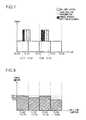
- Fig. 7 is a graph showing an example of the power that is consumed in a case where the timing for performing the battery charge and the power storage portion discharge is controlled by means of a preferred method, and corresponds to Fig. 5 that shows the above preferred method.
- Fig. 8 is a graph showing the system power amount that is consumed during each unit time duration in the case where the timing for performing the battery charge and the power storage portion discharge is controlled as shown in Fig. 7 , and corresponds to Fig. 6 that shows the above preferred method.
- Fig. 7 is identical to Fig. 5 except that the timing for performing the battery charge is different from the timing shown in Fig. 5 and the power supplied by the power storage portion discharge is used for the battery charge. Because of this, in Fig.
- Fig. 7 hereinafter, description of the same portions as in Fig. 5 is skipped, and different portions are described in detail.
- Fig. 7 the size of the power, which is supplied by the power storage portion discharge and consumed by the battery charge, is shown by means of a height of a black region.
- an upper limit in the present example, half of the system power amount consumed by the one battery charge
- the system power amount consumed by the battery charge is set on the system power amount consumed by the battery charge. Because of this, as shown in Fig. 8 , it becomes possible to make the system power amounts WP1, WP2, and WR consumed during the respective unit time durations relatively small. For example, it becomes possible to make them equal to or smaller than the power amount WP1 shown in Fig. 6 . Accordingly, it becomes possible to effectively alleviate the maximum value of the system power amount consumed during the unit time duration, and it becomes possible to further decrease the power rate.
- the time duration for performing the battery charge by a time duration that corresponds to the power amount suppliable by the power storage portion discharge. For example, if the power amount suppliable by the power storage portion discharge is equal to 1/4 of the power amount consumed by the battery charge, it becomes possible to change the time duration for performing the battery charge by 1/4 (in the above example, five minutes) from the reference time duration.
- the power storage portion discharge is performed to supply the power; however, during a predetermined time duration before the end of the battery charge, the power storage portion discharge may be performed to supply the power.
- the power storage portion discharge may be performed during a predetermined time duration after the start of the battery charge, while in a case where the time duration for performing the battery charge is moved backward of the reference time duration, the power storage portion discharge may be performed during a predetermined time duration before the end of the battery charge.
- the battery charge consuming the system power and the battery charge consuming the power supplied by the power storage portion discharge are separately performed; however, they may be performed concurrently with each other. Specifically, for example, in the battery charge during the time duration of 12:15-12:35 in Fig. 7 , instead of supplying the power from 12:15 to 12:20 by means of the power storage portion discharge, 1/3 of the power may be dispersedly supplied from 12:15 to 12:30.
- the system power amount consumed by the charge portion 11 is likely to become small. Because of this, during these time durations, the power storage portion charge may be performed by means of the system power.
- the time durations shown in Fig. 5 and Fig. 7 are measured by a watch that comes with a wattmeter and the like installed by an electric power company, and there is a case where a deviation occurs with respect to an actual time. It is preferable that thanks to this deviation, for example, the unit time duration ranges from 10 minutes to 40 minutes and from 40 minutes to 10 minutes of every hour in actual time. In this case, it becomes possible to set the start time of the reference time duration at 0 minutes of every hour (or 30 minutes is all right). Because of this, it becomes possible to set a time, which is clear and easy for the user to memorize, as the start time of the battery charge.
- the size of the power consumed by the battery charge is constant irrespective of time; however, it may not be constant.
- the middle time point of the battery charge may be deviated from the time point at the boundary between the two unit time durations.
- the middle time point of the battery charge and the time point at the boundary between the two unit time durations may be set to become substantially equal to each other.
- each specific example of the charge schedule is described hereinafter with reference to drawings.
- each specific example of the charge schedule described hereinafter uses (controls not only the timing for performing the battery charge but also the timing for performing the power storage portion discharge) the power storage portion discharge as shown Fig. 7 and Fig. 8 .
- each specific example of the charge schedule described hereinafter controls not only the timing for performing the battery charge and power storage portion discharge but also the timing for performing the power storage portion charge.
- each specific example of the charge schedule described hereinafter envisions a case where the charge system 1 needs to frequently perform the battery charge.
- the number of unit time durations for the one battery charge is smaller than 2 and it becomes hard to perform, a plurality of times, the battery charge (e.g., see Fig. 5 and Fig. 7 ) which bridges two unit time durations.
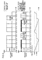
- Fig. 9 is a graph showing the first specific example of the charge schedule.
- a graph on a top stage of Fig. 9 is a graph showing an example of the power that is consumed in a case where the timing for performing the battery charge, the power storage portion discharge and the power storage portion charge is controlled by means of an undesirable method, and corresponds to Fig. 3 .
- a graph on a middle stage of Fig. 9 is a graph showing an example of the power that is consumed in a case where the timing for performing the battery charge, the power storage portion discharge and the power storage portion charge is controlled by means of a preferable method.
- a graph on a bottom stage of Fig. 9 is a graph showing the power amount (remaining capacity) stored in the power storage portion 12 in a case where the timing for performing the battery charge, the power storage portion discharge and the power storage portion charge is controlled as shown in the graph on the middle stage.
- the size of the system power consumed by the battery charge is shown by means of a height of a white region; the size of the system power consumed by the load portion consumption is shown by means of a height of a grey region; and the size of the power supplied by the power storage portion discharge is shown by means of a height of a black region. Further, the size of the system power consumed by the power storage portion charge is shown by means of a height of a region marked by checker-shaped hatching. In insides of some typical regions, the system power amount consumed during the unit time duration and the power amount supplied by the power storage portion discharge during the unit time duration and consumed are represented.
- a case is envisioned where a power amount of 15 kWh is consumed during each unit time duration by the load portion consumption; and a power amount of 20 kWh (which is equal to 80% of the power amount (capacity) that the battery B of the general electric vehicle C is able to charge) is consumed by the one battery charge.
- a case is envisioned where four (four electric vehicles C) battery charges are performed within five unit time durations (12:00-14:30, 14:30-17:00); and the one battery charge takes 30 minutes.
- the power storage portion 12 has a sufficient amount of remaining capacity (11 kWh) at a start time (12:00) of the charge schedule in the present specific example.
- the basic rate for one year is obtained by a translated value for one hour of the maximum value (35 ⁇ 2) ⁇ a unit price (1600) of the basic rate per month ⁇ one year (12), it reaches about 1.34 million yen.
- control portion 15 controls the charge portion 11 and the power storage portion 12.
- one of the four battery charges is performed bridging the two unit time durations as described above (see Fig. 5 ).
- the last (or first) battery charge of the four is performed bridging the two unit time durations (13:30-14:30, 16:00-17:00).
- the middle time point (14:00, 16:30) of the battery charge and the time point (14:00, 16:30) at the boundary between the two unit time durations are made to become substantially equal to each other. According to this, it becomes possible to effectively decrease the maximum value of the system power amount consumed during each of the two unit time durations.
- the three battery charges other than the above battery charge are performed during every three unit time durations (12:00-13:30, 14:30-16:00) other than the above two unit time durations (13:30-14:30, 16:00-17:00).
- the power storage portion discharge is performed during each of the unit time durations.
- a power amount (at a discharge efficiency of 85%, 11 ⁇ 3 ⁇ 0.85 ⁇ 3.1 kWh) substantially equal to 1/3 of the remaining capacity of the power storage portion 12 is supplied, and it becomes possible to effectively decrease the maximum value of the system power amount consumed during each of the unit time durations.
- the power storage portion charge is performed during each of the two unit time durations (13:30-14:30, 16:00-17:00) during which the one battery charge is performed.
- the system power amount (11 ⁇ 0.85 ⁇ 2 ⁇ 6.5 kWh in a case of obtaining the remaining capacity of 11 kWh at the charge efficiency of 85% before the power storage portion charge) consumed by the power storage portion charge during each of the two unit time durations is set small such that the system power amount consumed during each of the two unit time durations does not exceed the system power amount (31.9 kWh) consumed during the other unit time durations, it is possible to effectively decrease the maximum value of the system power amount consumed during the unit time duration, which is preferable.
- the system power amount (6.5 kWh) consumed by the power storage portion charge during each of the two unit time durations (13:30-14:30, 16:00-17:00) during which the one battery charge is performed is large such that a sufficient amount of power (3.1 kWh) is suppliable by the power storage portion discharge during the other unit time durations.
- the power amount for the power storage portion charge and for the power storage portion discharge may be set, or the power storage portion 12 having a capacity, which is able to charge and discharge the power amount, may be selected such that a difference among the system power amounts consumed during the five respective unit time durations during which the four battery charges are performed becomes small.
- the system power amount consumed by the one battery charge is distributed to the two unit time durations. Besides, during the other unit time durations, the battery charge, which consumes the power supplied by the power storage portion discharge, is performed. Because of this, even in a case where it is necessary to frequently perform the battery charge, it becomes possible to decrease the maximum value of the system power amount consumed during the unit time duration. Accordingly, it becomes possible to decrease the power rate. For example, in a case where the basic rate is calculated by means of the above formula, it is possible to decrease the basic rate for one year to about 1.22 million yen.
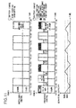
- Fig. 10 is a graph showing the second specific example of the charge schedule.
- respective graphs on top, middle and bottom stages of Fig. 10 correspond to the respective graphs on the top, middle and bottom stages of Fig. 9 that are shown in the first specific example. Because of this, description of each graph of Fig. 10 is skipped and the description of Fig. 9 is used for it.
- a case is envisioned where a power amount of 15 kWh is consumed during each unit time duration by the load portion consumption; and a power amount of 20 kWh is consumed by the one battery charge.
- the one battery charge takes 30 minutes and the power storage portion 12 has a sufficient amount of remaining capacity (9 kWh) at a start time (12:00) of the charge schedule.
- a case is envisioned where three (three electric vehicles C) battery charges are performed during four unit time durations (12:00-14:00, 14:00-16:00).
- the basic rate for one year reaches about 1.34 million yen.
- control portion 15 controls the charge portion 11 and the power storage portion 12.
- one of the three battery charges is performed bridging the two unit time durations as described above (see Fig. 5 ).
- the last (or first) battery charge of the three is performed bridging the two unit time durations (13:00-14:00, 15:00-16:00).
- the middle time point (13:30, 15:30) of the battery charge and the time point (13:30, 15:30) at the boundary between the two unit time durations are made to become substantially equal to each other. According to this, it becomes possible to effectively decrease the maximum value of the system power amount consumed during each of the two unit time durations.
- the two battery charges other than the above battery charge are performed during every two unit time durations (12:00-13:00, 14:00-15:00) other than the above two unit time durations (13:00-14:00, 15:00-16:00).
- the power storage portion discharge is performed during each of the unit time durations.
- a power amount (at a discharge efficiency of 85%, 9 ⁇ 2 ⁇ 0.85 ⁇ 3.8 kWh) substantially equal to 1/2 of the remaining capacity of the power storage portion 12 is supplied, and it becomes possible to decrease the maximum value of the system power amount consumed during each of the unit time durations.
- the power storage portion charge is performed during each of the two unit time durations (13:00-14:00, 15:00-16:00) during which the one battery charge is performed.
- the system power amount (9 ⁇ 0.85 ⁇ 2 ⁇ 5.3 kWh in a case of obtaining the remaining capacity of 9 kWh at the charge efficiency of 85% before the power storage portion discharge) consumed by the power storage portion charge during each of the two unit time durations is set small such that the system power amount consumed during each of the two unit time durations does not exceed the system power amount (31.2 kWh) consumed during the other unit time durations, it is possible to effectively decrease the maximum value of the system power amount consumed during the unit time duration, which is preferable.
- the system power amount (5.3 kWh) consumed by the power storage portion charge during each of the two unit time durations (13:00-14:00, 15:00-16:00) during which the one battery charge is performed is large such that a sufficient amount of power (3.8 kWh) is suppliable by the power storage portion discharge during the other unit time durations.
- the power amount for the power storage portion charge and for the power storage portion discharge may be set, or the power storage portion 12 having a capacity, which is able to charge and discharge the power amount, may be selected such that a difference among the system power amounts consumed during the four respective unit time durations during which the three battery charges are performed becomes small.
- the system power amount consumed by the one battery charge is distributed to the two unit time durations. Besides, during the other unit time durations, the battery charge, which consumes the power supplied by the power storage portion discharge, is performed. Because of this, even in a case where it is necessary to frequently perform the battery charge, it becomes possible to decrease the maximum value of the system power amount consumed during the unit time duration. Accordingly, it becomes possible to decrease the power rate. For example, in a case where the basic rate is calculated by means of the above formula, it is possible to decrease the basic rate for one year to about 1.20 million yen.
- the number of battery charges able to be performed during a predetermined time duration decreases, however, it becomes possible to dramatically decrease the power rate.
- even the capacity of the power storage portion 12 smaller than the first specific example is sufficient, accordingly, it becomes possible to achieve simplification of the structure of and low cost of the charge system 1.
- Fig. 11 is a graph showing the third specific example of the charge schedule.
- respective graphs on top, middle and bottom stages of Fig. 11 correspond to the respective graphs on the top, middle and bottom stages of Fig. 9 that are shown in the first specific example. Because of this, description of each graph of Fig. 11 is skipped and the description of Fig. 9 is used for it.
- a case is envisioned where a power amount of 15 kWh is consumed during each unit time duration by the load portion consumption; and a power amount of 20 kWh is consumed by the one battery charge.
- the one battery charge takes 30 minutes and the power storage portion 12 has a sufficient amount of remaining capacity (6 kWh) at a start time (12:00) of the charge schedule.
- two (two electric vehicles C) battery charges are performed within three unit time durations (12:00-13:30, 13:30-15:00, 15:00-16:30).
- the basic rate for one year reaches about 1.34 million yen.
- control portion 15 controls the charge portion 11 and the power storage portion 12.
- one of the two battery charges is performed bridging the two unit time durations as described above (see Fig. 5 ).
- either of the two battery charges is performed bridging the two unit time durations (12:30-13:30, 14:00-15:00, 15:30-16:30).
- the middle time point (13:00, 14:30, 16:00) of the battery charge and the time point (13:00, 14:30, 16:00) at the boundary between the two unit time durations are made to become substantially equal to each other. According to this, it becomes possible to effectively decrease the maximum value of the system power amount consumed during each of the two unit time durations.
- the one battery charge other than the above battery charge is performed during the one unit time duration (12:00-12:30, 13:30-14:00, 15:00-15:30) other than the above two unit time durations (12:30-13:30, 14:00-15:00, 15:30-16:30).
- the power storage portion discharge is performed during the unit time duration.
- a power amount (at a discharge efficiency of 85%, 6 ⁇ 0.85 ⁇ 5.1 kWh) substantially equal to the remaining capacity of the power storage portion 12 is supplied, and it becomes possible to decrease the maximum value of the system power amount consumed during each of the unit time durations.
- the power storage portion charge is performed during each of the two unit time durations (12:30-13:30, 14:00-15:00, 15:30-16:30) during which the one battery charge is performed.
- the system power amount (6 ⁇ 0.85 ⁇ 2 ⁇ 3.5 kWh in a case of obtaining the remaining capacity of 6 kWh at the charge efficiency of 85% before the power storage portion discharge) consumed by the power storage portion charge during each of the two unit time durations is set small such that the system power amount consumed during each of the two unit time durations does not exceed the system power amount (29.9 kWh) consumed during the other unit time durations, it is possible to effectively decrease the maximum value of the system power amount consumed during the unit time duration, which is preferable.
- the system power amount (3.5 kWh) consumed by the power storage portion charge during each of the two unit time durations (12:30-13:30, 14:00-15:00, 15:30-16:30) during which the one battery charge is performed is large such that a sufficient amount of power (5.1 kWh) is suppliable by the power storage portion discharge during the other unit time durations.
- the power amount for the power storage portion charge and for the power storage portion discharge may be set, or the power storage portion 12 having a capacity, which is able to charge and discharge the power amount, may be selected such that a difference among the system power amounts consumed during the three respective unit time durations during which the two battery charges are performed becomes small.
- the system power amount consumed by the one battery charge is distributed to the two unit time durations. Besides, during the other unit time durations, the battery charge, which consumes the power supplied by the power storage portion discharge, is performed. Because of this, even in a case where it is necessary to frequently perform the battery charge, it becomes possible to decrease the maximum value of the system power amount consumed during the unit time duration. Accordingly, it becomes possible to decrease the power rate. For example, in a case where the basic rate is calculated by means of the above formula, it is possible to decrease the basic rate for one year to about 1.15 million yen.
- the number of battery charges able to be performed during a predetermined time duration decreases, however, it becomes possible to more dramatically decrease the power rate.
- even the capacity of the power storage portion 12 smaller than the first and second specific examples is sufficient, accordingly, it becomes possible to achieve simplification of the structure of and low cost of the charge system 1.
- n is an integer that is 2 or larger. It may be understood as one set that the control portion 15 "performs n battery charges during n+1 unit time durations.”
- a charge schedule combining control methods e.g., see Fig. 9 to Fig. 11 ) corresponding to the respective sets may be prepared.
- the power storage portion charge may be performed in any way during two unit time durations during which the one battery charge is performed.
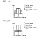
- An execution example of this power storage portion charge is described with reference to Fig. 12.
- Fig. 12 is a graph showing the execution example of the power storage portion charge.
- Fig. 12 corresponds to the graph on the middle stage of Fig. 9 . Because of this, description of the graph of Fig. 12 is skipped and the description of the graph on the middle stage of Fig. 9 is used for it.
- Fig. 12 (a) is the same as that shown in the graph on the middle stage of each of Fig. 9 to Fig. 11 . Specifically, during the two unit time durations, the power storage portion charge is performed by one before and after the one battery charge that is performed bridging the two unit time durations.
- the power storage portion charge is performed by one irrespective of presence of the battery charge.
- the power storage portion charge in the present example is performed bridging the two unit time durations.
- Fig. 12 (a) and (b) the system power amounts consumed during the respective unit time durations become equal to each other.
- the power storage portion charge in Fig. 12 (a) it is alleviated that the battery charge and the power storage portion charge overlap each other, accordingly, it becomes possible to decrease the maximum value of the consumed system power.
- Fig. 12 (b) it alleviated that the power storage portion charge is divided by the battery charge, accordingly, it becomes possible to continuously perform the power storage portion charge at a time.
- the case is described as an example in which the power storage portion charge is performed during the two unit time durations during which the one battery charge is performed; however, the power storage portion charge may be performed during either one. However, from the viewpoint of decreasing the system power amount consumed during the unit time duration, it is preferable to perform the power storage portion charge bridging the two unit time durations like the battery charge.
- the power may be consumed for the load portion consumption.
- the operation of part or all of portions such as the control portion 15 and the like may be performed by a control device such as a micro-computer and the like. Further, by writing all or part of the functions achieved by such a control device as a program and performing the program on a program execution device (e.g., a computer), all or part of the functions may be achieved.
- a control device such as a micro-computer and the like.
- the charge system 1 shown in Fig. 1 is achievable by hardware or a combination of hardware and software.
- a block related to the part achieved by the software represents a function block of the part.
- the present invention is applicable to a charge system that charges a battery and the like which are disposed in an electric vehicle. Especially, it is preferable to apply the present invention to a charge system that consumes large power and is able to perform a rapid charge during a time duration which is equal to or shorter than a unit time duration.
Landscapes
- Engineering & Computer Science (AREA)
- Power Engineering (AREA)
- Transportation (AREA)
- Mechanical Engineering (AREA)
- Manufacturing & Machinery (AREA)
- Chemical & Material Sciences (AREA)
- Chemical Kinetics & Catalysis (AREA)
- Electrochemistry (AREA)
- General Chemical & Material Sciences (AREA)
- Charge And Discharge Circuits For Batteries Or The Like (AREA)
- Secondary Cells (AREA)
- Electric Propulsion And Braking For Vehicles (AREA)
- Supply And Distribution Of Alternating Current (AREA)
Abstract
Description
- The present invention relates to a charge system that charges a battery and the like disposed in an electric vehicle.
- In recent years, a power storage battery is going large, studied so as to be used for: driving of electric vehicles such as an electric car, an electric bike and the like; and storing power that is consumed in households, stores, buildings and the like, and is expected to be widespread in the fixture. Besides, from the viewpoint of reduction in emission amount of carbon dioxide and the like, an electric vehicle is desired to be widespread.
- For the spread of an electric vehicle, the spread of a charge system, which charges a power storage battery (hereinafter, called a battery) for driving an electric vehicle, is inevitable. Especially, the spread of a charge system, which charges a battery of an electric vehicle outside a household, is inevitable. Regarding this, a plan is proposed so as to dispose a charge system at stores such as a convenience store and the live.
- In a case where a charge system is disposed at a store and the like, besides power that is consumed by various apparatuses such as an illumination device, an air conditioner, a refrigerator and the like, it is also necessary for the store and the like to supply power that is consumed by the charge system. The power consumed by a charge system is likely to be equal in amount to (e.g., substantially equal to each other in the order of power) the power consumed by various apparatuses in a store and the like. Because of this, the power amount which a store and the like purchase from an electric power company increases, which becomes a problem that the power rate increases, and the problem is likely to become a cause that discourages the spread of a charge system.
- Accordingly, for example, a
patent document 1 proposes a charge system, which preferentially uses a time zone where a unit power rate is inexpensive and a time zone where power is in less demand, thereby reducing the power rate. - PLT1:
JP-A-2008-67418 - According to the charge system proposed by the
patent document 1, it is impossible to decrease the power rate without performing a charge during time zones such as late night, early morning and the like which are inconvenient and limited. However, it is conceivable that there are few cases where an electric vehicle user (hereinafter, simply called a user) comes to a store and the like at late night, in early morning and the like that are inconvenient time zones to perform a charge. Besides, in contrast, during time zones such as daytime and the like that are convenient for the user, it is conceivable that many electric vehicles come to a store and the like; accordingly, it becomes necessary to frequently perform a charge. Accordingly, it becomes hard to decrease the power rate by means of the above charge system. - Accordingly, it is an object of the present invention to provide a charge system that does not set a limit on a time zone where to perform a charge and allows reduction or a power rate even if a charge is frequently performed.
- To achieve the above object, a charge system according to the present invention is a charge system that charges a battery and includes: a power storage portion that consumes system power supplied from an electric company to be charged and supplies the charged power by means of a discharge; and a charge portion that consumes the system power and the power supplied from the power storage portion to charge the battery; wherein at least one charge performed by the charge portion is performed bridging two unit time durations, and the power storage portion supplies the power to the charge portion during at least one unit time duration other than the two unit time durations.
- Besides, in the charge system having the above structure, the power rate set by the electric power company may include a fixed basic rate and a measured use rate, and the basic rate may become higher as the maximum value of the power amount supplied during the unit time duration becomes larger.
- Besides, in the charge system having the above structure, the charge of the power storage portion may be performed during at least one of the two unit time durations during which the one charge of the charge system is performed.
- According to this structure, it becomes possible to secure timing to perform the charge of the power storage portion. Because of this, it becomes possible to alleviate a situation, in which it becomes hard to decrease the maximum value of the system power amount consumed during the unit time duration thanks to a less remaining capacity of the power storage portion, occurring.
- Besides, in the charge system having the above structure, in a case where the charge portion performs n (n is an integer that is 2 or larger) charges, each of which takes a time duration equal to or shorter than the unit time duration, during n +1 unit time durations, the one charge of the charge portion may be performed bridging the two unit time durations and other n-1 charges may be performed during each of n-1 unit time durations other than the two unit time durations.
- According to this structure, even in a case where the number of unit time durations for the one charge by the charge portion is smaller than 2 and it becomes hard to perform, a plurality of times, the charge of the charge portion which bridges the two unit time durations, it becomes possible to decrease the maximum value of the system power amount that is consumed during the unit time duration.
- Besides, in the charge system having the above structure, the system power amount, which is consumed during each of the two unit time durations during which the one charge of the charge portion is performed, may not exceed the system power amount that is consumed during the other unit time durations.
- According to this structure, it becomes possible to effectively decrease the maximum value of the system power amount that is consumed during the unit time duration.
- Besides, in the charge system having the above structure, the charge of the power storage portion may be performed by one each before and after the one charge during the two unit time durations during which the one charge of the charge portion is performed.
- According to this structure, it is alleviated that the charge by the charge portion and the charge of the power storage portion overlap each other, accordingly, it becomes possible to decrease the maximum value of the consumed system power.
- Besides, in the charge system having the above structure, one charge of the power storage portion may be performed during the two unit time durations during which the one charge of the charge portion is performed.
- According to this structure, it is alleviated that the charge of the power storage portion is divided by the charge by the charge portion, accordingly, it becomes possible to continuously perform the charge of the power storage portion at a time.
- Besides, in the charge system having the above structure, a middle time point of at least one charge of the charge portion and a time point at a boundary between the two unit time durations may be made to become substantially equal to each other.
- According to this structure, it becomes possible to effectively decrease the maximum value of the system power amount that is consumed during the two unit time durations.
- Besides, in the charge system having the above structure, in a case where a plurality of the charges are performed by the charge portion, the unit time durations during which the respective charges are performed may be different from one another.
- According to this structure, it is alleviated that the system power amounts consumed by the plurality of the charges of the charge portions overlap one another during a unit time duration. Because of this, it becomes possible to alleviate that the system power amount consumed during the unit time duration increases.
- According to the structure of the present invention, the system power amount consumed by the one charge of the charge portion is distributed to the two unit time durations. Besides, during the other unit time durations, by consuming the power supplied by the discharge from the power storage portion, the charge portion performs the charge. Because of this, even in a case where the charge portion needs to frequently perform the charge, it becomes possible to decrease the maximum value of the system power amount consumed during the unit time duration. Accordingly, it becomes possible to decrease the power rate.
- The significance and effects of the present invention will be more apparent from embodiments described hereinafter. However, the following embodiments are each an embodiment of the present invention, and the present invention and the meaning of a term of each constituent element are not limited to those described in the following embodiments.
-
- [
Fig. 1 ] is a block diagram showing a structural example of a charge system according an embodiment of the present invention. - [
Fig. 2 ] is a graph showing an overview of a method for calculating a power rate of system power. - [
Fig. 3 ] is a graph showing an example of power that is consumed in a case where timing for performing a battery charge is controlled by an undesirable method. - [
Fig. 4 ] is a graph showing a system power amount that is consumed during each unit time duration in the case where the timing for performing the battery charge is controlled as shown inFig. 3 . - [
Fig. 5 ] is a graph showing an example of power that is consumed in a case where the timing for performing a battery charge is controlled by a preferred method. - [
Fig. 6 ] is a graph showing a system power amount that is consumed during each unit time duration in the case where the timing for performing the battery charge is controlled as shown inFig. 5 . - [
Fig. 7 ] is a graph showing an example of power that is consumed in a case where timings for performing a battery charge and a power storage portion discharge are controlled by means of a preferred method. - [
Fig. 8 ] is a graph showing a system power amount that is consumed during each unit time duration in the case where the timings for performing the battery charge and power storage portion discharge are controlled as shown inFig. 7 . - [
Fig. 9 ] is a graph showing a first specific example of a charge schedule. - [
Fig. 10 ] is a graph showing a second specific example of a charge schedule. - [
Fig. 11 ] is a graph showing a third specific example of a charge schedule. - [
Fig. 12 ] is a graph showing an execution example of a power storage portion charge. - A charge system according to an embodiment of the present invention is described hereinafter with reference to drawings. First, an example of a structure and operation of the charge system according to the embodiment of the present invention is described with reference to drawings.
-
Fig. 1 is a block diagram showing a structural example of the charge system according the embodiment of the present invention. Here, a solid-line arrow, which connects blocks in the figure to each other, shows a flow of power, and a broken-line arrow shows a flow of information. - The
charge system 1 shown inFig. 1 includes: acharge portion 11 that consumes supplied power, supplies power to and charges a battery B disposed in an electric vehicle C; apower storage portion 12 that stores supplied power and supplies the power by means of a discharge; aninput portion 13 into which a command from a user is input; anotification portion 14 that gibes notice to the user; and acontrol portion 15 into which the command from the user is input from theinput portion 13 and which controls operation of thecharge portion 11 and thepower storage portion 12. In the meantime, hereinafter, the charge of the battery B of the electric vehicle C by thecharge portion 11 is called a battery charge and the charge of thepower storage portion 12 is called a power storage portion charge, whereby these are distinguished from each other. Besides, the discharge from thepower storage portion 12 is called a power storage portion discharge. - Power (hereinafter, called system power) supplied from an electric power company is supplied to the
charge system 1. The system power is also supplied to various apparatuses (e.g, an illumination device, an air conditioner, a refrigerator and the like, hereinafter, called a load portion R) in a store and the like provided with thecharge system 1 and is consumed. - The
charge portion 11 suitably converts (e.g., converts a.c. power into d.c. power, or adjusts a voltage value of d.c. power supplied to the battery B of the electric vehicle C) the system power and the power supplied by a power storage portion discharge from thepower storage portion 12, thereby performing the battery charge. - The
power storage portion 12 converts (e.g., converts a.c. power into d.c. power, or adjusts a voltage value of the d.c. power) the supplied system power when necessary and performs the power storage portion charge. The power storage portion applies the power storage portion discharge to the power consumed (stored in the power storage portion 12) by the power storage portion charge, thereby supplying the power to thecharge portion 11. Here, a structure may be employed, in which the power supplied by the power storage portion discharge is supplied to the load portion R. - The
input portion 13 is operated by the user or receives the command transmitted from a user's possession (e.g, a mobile terminal and the like), whereby the user's command is input. Besides, theinput portion 13 transmits the input user's command to thecontrol portion 15. As the user's command, for example, there are a command for starting the battery charge, a command for making a reservation for the battery charge, and a command for stopping the battery charge. - The
notification portion 14 includes, for example, a display device, a speaker and the like, outputs an image and a voice, or includes a transmission device, and transmits information to the user's possession (e.g., a mobile terminal that is registered beforehand in the charge system 1), thereby giving notice to the user. As the content which the notification portion gives to the user, there are, for example, timing for performing a reserved battery charge, a start, an end and a stop of the battery charge. - The
control portion 15 controls the battery charge by thecharge portion 11, the power storage portion charge and power storage portion discharge of thepower storage portion 12. Upon confirming that the command for making a reservation for the battery charge is input into theinput portion 12, thecontrol portion 15 prepares a charge schedule based on the command. And, thecontrol portion 15 controls thenotification portion 14, thereby giving notice of part or all of the charge schedule to the user. - Besides, the
control portion 15 prepares a charge schedule which allows reduction of a power rate charged to a store and the like without setting a limit on a time zone where to perform the batter charge. And, based on the prepared charge schedule, the control portion controls the operation of thecharge portion 11 and thepower storage portion 12. In the meantime, details of the charge schedule (i.e., methods for controlling the timing thecharge portion 11 performs the battery charge and the timing thepower storage portion 12 performs the power storage portion charge and power storage portion discharge) are described later. - The charge schedule can include a start time and an end time of the battery charge. Besides, times at which the power storage portion charge and power storage portion discharge start can be included. The user is notified of the charge schedule by the
notification portion 14, thereby recognizing at least the battery charge start time. According to this structure, it becomes possible to alleviate a situation (charge waiting) occurring in which when the user goes to a store and the like to perform the battery charge, other users are already performing the battery charge and the user cannot perform the battery charge early. - Besides, the
charge system 1 is able to alleviate the occurrence of charge waiting and decrease the power rate, accordingly, becomes preferable to the user side and the side of a store and the like as well. Because of this, thecharge system 1 is expected to become widespread. And, by spreading thecharge system 1, it becomes possible to promote the spread of electric vehicles and to achieve reduction in emission amount of carbon dioxide. - Here, the structure of the charge system shown in
Fig. 1 is only an example, and another structure may be employed. For example, a structure may be employed, in which the charge system includes another power supply (e.g., a solar battery and the like) that is able to supply power to thecharge portion 11, thepower storage portion 12, the load portion R and the like. - Besides, the
charge portion 11 may be connectable to only one electric vehicle C to which the battery charged is applied, or may be connectable to a plurality of the electric vehicles C. Besides, in a case of the structure in which thecharge portion 11 is connectable to the plurality of the electric vehicles C, a structure may be employed, in which thecontrol portion 15 controls thecharge portion 11, thereby applying the battery charges to the respective batteries B of the electric vehicles C connected to thecharge portion 11 one after another. - Next, a method example for calculating the power rate of the system power is described with reference to drawings.
Fig. 2 is a graph showing an overview of the method for calculating the power rate of the system power. Here, the graph shown inFig. 2 shows, by means of a graph height, the system power amount, which is consumed by the entire store and the like which have thecharge system 1, for each of unit time durations (for every 30 minutes of a first half of 00-30 minutes and a second half of 30 to 00 minutes of every hour) of 12:00-12:30, 12:30-13:00, 13:00-13:30, and 13:30-14:00. - The power rate of the system power includes, for example, a fixed basic rate and a measured use rate. Generally, because of a reason for effective power generation (leveled power generation) and the like, an electric power company sets a higher basic rate as the maximum value of the system power amount consumed during a unit time duration becomes larger.
- In the example shown in
Fig. 2 , a power amount WP consumed during a unit time duration of 13:00-13:30 is larger than the power amounts consumed during the other unit time durations, accordingly, becomes the maximum value. Because of this, based on the power amount WP consumed during the unit time duration of 13:00-13:30, the basic rate is set. Here, inFig. 2 , for the sake of simple description, only the four unit time durations are shown; however, a general electric power company calculates the maximum value of the power amounts from more unit time durations (e.g., for one year). - As described above, by decreasing the maximum value of the system power amount consumed during the unit time duration, it is possible to decrease the power rate (especially, the basic rate, hereinafter, the same applies). Hereinafter, a charge schedule (a control method by which the
control portion 15 controls the timing for performing the battery charge) for decreasing the maximum value of the system power amount consumed during the unit time duration is described with reference to drawings. First, for comparison, an undesirable method for controlling the timing for performing the battery charge is described with reference toFig. 3 and Fig. 4 . -
Fig. 3 is a graph showing an example of the power that is consumed in a case where the timing for performing the battery charge is controlled by an undesirable method. Besides,Fig. 4 is a graph showing the system power amount that is consumed during each unit time duration in the case where the timing for performing the battery charge is controlled as shown inFig. 3 . Both ofFig. 3 and Fig. 4 show the same time duration as the time duration (12:00-14:00) shown inFig. 2 . Besides, inFig. 3 , the size of the system power consumed by the battery charge is shown by means of a height of a white region, while the size of the system power consumed (hereinafter, called load portion consumption) by the load portion R is shown by means of a height of a grey region. - Besides, hereinafter, for the sake of simple description, as shown in
Fig. 3 , it is assumed that the size of the load portion consumption is constant irrespective of time. Because of this, as shown inFig. 4 , also power amounts WR by the load portion consumption during the respective unit time durations become constant. Besides, as shown inFig. 3 , it is also assumed that the power size, which is consumed (charged into the battery B of the electric vehicle C) by the battery charge, is constant irrespective of time. Further, as shown inFig. 3 , it is assumed that a time duration (a charge time duration for one electric vehicle C) required for one battery charge is a time duration (20 minutes) that is equal to or shorter than the unit time duration (30 minutes) and becomes the same time duration for every charge. - In the example shown in
Fig. 3 , during a time duration of 12:00-12:20 and during a time duration of 13:05-13:25, the battery charge by thecharge portion 11 is performed. Both time durations are confined within the unit time duration (12:00-12:30,13:00-13:30). - When the battery charge is performed as shown in
Fig. 3 , the total power amount consumed by one battery charge becomes equal to the system power amount that is consumed by thecharge portion 11 during one unit time duration. Especially, according to a rapid charge by which the battery charge is performed during a time duration equal to or shorter than the unit time duration, the consumed power becomes large. Because of this, the system power amount consumed during one unit time duration is likely to become large. Accordingly, as shown inFig. 4 , a system power amount WPU consumed during the unit time duration (12:00-12:30, 13:00-13:30), during which the battery charge is performed, becomes relatively large. - In this case, based on at least the power amount WPU for the unit time duration (12:00-12:30, 13:00-13:30), during which the battery charge is performed, the power rate (basic rate) is set. Accordingly, the power rate is likely to increase.
- In contrast to this, a preferred method for controlling the timing for performing the battery charge is described with reference to
Fig. 5 and Fig. 6 . -
Fig. 5 is a graph showing an example of the power that is consumed in a case where the timing for performing the battery charge is controlled by means of a preferred method, and corresponds toFig. 3 that shows the undesirable control method.Fig. 6 is a graph showing a system power amount that is consumed during each unit time duration in the case where the timing for performing the battery charge is controlled as shown inFig. 5 , and corresponds toFig.4 that shows the undesirable control method. Here,Fig. 5 is identical toFig. 3 except that the timing at which the battery charge is performed is different from the timing shown inFig. 3 . Because of this, inFig. 5 , description of the same portions as inFig. 3 is skipped, and different portions are described in detail. - In the example shown in
Fig. 5 , during each of a time duration of 12:20-12:40 and a time duration of 13:25-13:45, the battery charge is performed. Both of the time durations during which the battery charge is performed extend into (bridge) the unit time durations (12:00-12:30 and 12:30-13:00, 13:00-13:30 and 13:30-14:00) that are different (do not overlap) from each other. - According to the above structure, even in a case (e.g., a case where a rapid charge is performed) where the power consumed to perform the battery charge during a time duration equal to or shorter than the unit time duration is prone to become large, it becomes possible to distribute the system power amount consumed by one battery charge to the two unit time durations. Because of this, as shown in
Fig. 6 , it becomes possible to make the system power amounts WP1 to WP3 consumed during the respective unit time durations relatively small. For example, it becomes possible to make them smaller than the power amount WPU shown inFig. 4 . Accordingly, it becomes possible to alleviate the maximum value of the system power amount consumed during the unit time duration, and it becomes possible to decrease the power rate. - Further, it is enough to only slightly change the time duration for performing the battery charge, accordingly, it is not necessary to limit the time zone for performing the battery charge to late night, early morning and the like. Accordingly, it becomes possible to easily decrease the power rate without limiting the time zone for performing the battery charge.
- Besides, in a case where the
charge portion 11 performs a plurality of the battery charges, the timing for performing each battery charge bridges unit time durations different form each other. Because of this, it becomes possible to alleviate an increase in the system power amount consumed during the unit time durations which is caused by distributing the system power amount, which is consumed by the plurality of the battery charges, to the overlapping unit time durations. - In the meantime, in the battery charge that is performed during the time duration of 12:20-12:40 shown in
Fig. 5 , the middle time point (12:30) and the time point (12:30) at the boundary between the two unit time durations are substantially equal to each other. According to this structure, it becomes possible to easily distribute the system power amount consumed by the one battery charge substantially equally to the two unit time durations. Because of this, it becomes possible to effectively alleviate the maximum value of the system power amount consumed during the unit time duration (hereinafter, the time duration when the battery charge is performed is called a "reference time duration"). - However, because of various circumstances (e.g., a change in the battery charge start time due to a reason of the user), it is hard to perform the control such that the battery charge is surely performed during the reference time duration (in the above example, 20 to 40 minutes (or 50 to 10 minutes of every hour also is all right) of every hour). Besides, if the time duration for performing the battery charge is limited more than necessary, it becomes hard to effectively perform the battery charge.
- To avoid this, hereinafter, with reference to
Fig. 7 and Fig. 8 , a charge schedule (a control method that is performed by thecontrol portion 15 to control the timing for performing the battery charge and the power storage portion discharge) is described which is able to tolerate a change in the time duration for performing the battery charge while effectively alleviating the maximum value of the system power amount consumed during the unit time duration. -
Fig. 7 is a graph showing an example of the power that is consumed in a case where the timing for performing the battery charge and the power storage portion discharge is controlled by means of a preferred method, and corresponds toFig. 5 that shows the above preferred method.Fig. 8 is a graph showing the system power amount that is consumed during each unit time duration in the case where the timing for performing the battery charge and the power storage portion discharge is controlled as shown inFig. 7 , and corresponds toFig. 6 that shows the above preferred method. Here,Fig. 7 is identical toFig. 5 except that the timing for performing the battery charge is different from the timing shown inFig. 5 and the power supplied by the power storage portion discharge is used for the battery charge. Because of this, inFig. 7 , hereinafter, description of the same portions as inFig. 5 is skipped, and different portions are described in detail. Here, inFig. 7 , the size of the power, which is supplied by the power storage portion discharge and consumed by the battery charge, is shown by means of a height of a black region. - In the example shown in
Fig. 7 , during each of a time duration of 12:15-12:35 and a time duration of 13:05-13:25, the battery charge is performed. However, during each of a time duration of 12:15-12:20 and a time duration of 13:05-13:15, not only the system power but also the power supplied by the power storage portion discharge are used to perform the battery charge. - According to the above structure, during each unit time duration, an upper limit (in the present example, half of the system power amount consumed by the one battery charge) is set on the system power amount consumed by the battery charge. Because of this, as shown in
Fig. 8 , it becomes possible to make the system power amounts WP1, WP2, and WR consumed during the respective unit time durations relatively small. For example, it becomes possible to make them equal to or smaller than the power amount WP1 shown inFig. 6 . Accordingly, it becomes possible to effectively alleviate the maximum value of the system power amount consumed during the unit time duration, and it becomes possible to further decrease the power rate. - Besides, it becomes possible to tolerate a change in the time duration for performing the battery charge by a time duration that corresponds to the power amount suppliable by the power storage portion discharge. For example, if the power amount suppliable by the power storage portion discharge is equal to 1/4 of the power amount consumed by the battery charge, it becomes possible to change the time duration for performing the battery charge by 1/4 (in the above example, five minutes) from the reference time duration.
- Accordingly, it becomes possible to tolerate the change in the time duration for performing the battery charge while effectively alleviating the maximum value of the system power amount consumed during the unit time duration. Specifically, for example, even if the user changes the time duration for performing the battery charge from the reserved time duration, it becomes possible to effectively decrease the power rate while performing the battery charge during the changed time duration.
- Besides, in the control methods shown in
Fig. 7 and Fig. 8 , in a case where a power amount equal to or more than 1/2 of the power amount consumed by the battery charge is suppliable by the power storage portion discharge, for example, it becomes possible to perform the battery charge during any time duration as shown by the battery charge during the time duration of 13:05-13:25 inFig. 7 . - Here, in
Fig. 7 , during a predetermined time duration after the start of the battery charge, the power storage portion discharge is performed to supply the power; however, during a predetermined time duration before the end of the battery charge, the power storage portion discharge may be performed to supply the power. Especially, in a case where the time duration for performing the battery charge is moved forward in the reference time duration, as shown inFig. 7 , the power storage portion discharge may be performed during a predetermined time duration after the start of the battery charge, while in a case where the time duration for performing the battery charge is moved backward of the reference time duration, the power storage portion discharge may be performed during a predetermined time duration before the end of the battery charge. - Besides, in
Fig. 7 , the battery charge consuming the system power and the battery charge consuming the power supplied by the power storage portion discharge are separately performed; however, they may be performed concurrently with each other. Specifically, for example, in the battery charge during the time duration of 12:15-12:35 inFig. 7 , instead of supplying the power from 12:15 to 12:20 by means of the power storage portion discharge, 1/3 of the power may be dispersedly supplied from 12:15 to 12:30. - According to this structure, it becomes possible to make the power supplied by the power storage portion discharge small. Because of this, it becomes possible to alleviate the
power storage portion 12 rapidly discharging (or charging) large power and to decrease the burden on thepower storage portion 12. Besides, even according to this structure, as described above, it is possible to effectively alleviate the maximum value of the system power amount consumed during the unit time duration. - Besides, in the case where the time duration for performing the battery charge is moved forward in the reference time duration, during the later unit time durations (in the example in
Fig. 8 , 12:30-13:00, 13:30-14:00), the system power amount consumed by thecharge portion 11 is likely to become small. Because of this, during these time durations, the power storage portion charge may be performed by means of the system power. - Besides, the time durations shown in
Fig. 5 andFig. 7 are measured by a watch that comes with a wattmeter and the like installed by an electric power company, and there is a case where a deviation occurs with respect to an actual time. It is preferable that thanks to this deviation, for example, the unit time duration ranges from 10 minutes to 40 minutes and from 40 minutes to 10 minutes of every hour in actual time. In this case, it becomes possible to set the start time of the reference time duration at 0 minutes of every hour (or 30 minutes is all right). Because of this, it becomes possible to set a time, which is clear and easy for the user to memorize, as the start time of the battery charge. - Besides, for the sake of simple description, the size of the power consumed by the battery charge is constant irrespective of time; however, it may not be constant. In this case, to substantially equally distribute the system power amount, which is consumed by the one battery charge, to the two unit time durations, the middle time point of the battery charge may be deviated from the time point at the boundary between the two unit time durations. Besides, also in this case, to simplify the control of the
charge portion 11 by thecontrol portion 15, the middle time point of the battery charge and the time point at the boundary between the two unit time durations may be set to become substantially equal to each other. - Each specific example of the charge schedule is described hereinafter with reference to drawings. Here, each specific example of the charge schedule described hereinafter uses (controls not only the timing for performing the battery charge but also the timing for performing the power storage portion discharge) the power storage portion discharge as shown
Fig. 7 and Fig. 8 . Further, each specific example of the charge schedule described hereinafter controls not only the timing for performing the battery charge and power storage portion discharge but also the timing for performing the power storage portion charge. - Besides, each specific example of the charge schedule described hereinafter envisions a case where the
charge system 1 needs to frequently perform the battery charge. Specifically, a case is envisioned where the number of unit time durations for the one battery charge is smaller than 2 and it becomes hard to perform, a plurality of times, the battery charge (e.g., seeFig. 5 andFig. 7 ) which bridges two unit time durations. - First, a first specific example of the charge schedule is described with reference to
Fig. 9. Fig. 9 is a graph showing the first specific example of the charge schedule. A graph on a top stage ofFig. 9 is a graph showing an example of the power that is consumed in a case where the timing for performing the battery charge, the power storage portion discharge and the power storage portion charge is controlled by means of an undesirable method, and corresponds toFig. 3 . A graph on a middle stage ofFig. 9 is a graph showing an example of the power that is consumed in a case where the timing for performing the battery charge, the power storage portion discharge and the power storage portion charge is controlled by means of a preferable method. A graph on a bottom stage ofFig. 9 is a graph showing the power amount (remaining capacity) stored in thepower storage portion 12 in a case where the timing for performing the battery charge, the power storage portion discharge and the power storage portion charge is controlled as shown in the graph on the middle stage. - In the graphs on the top and middle stages of
Fig. 9 , like inFig. 3 ,Fig. 5 andFig. 7 , the size of the system power consumed by the battery charge is shown by means of a height of a white region; the size of the system power consumed by the load portion consumption is shown by means of a height of a grey region; and the size of the power supplied by the power storage portion discharge is shown by means of a height of a black region. Further, the size of the system power consumed by the power storage portion charge is shown by means of a height of a region marked by checker-shaped hatching. In insides of some typical regions, the system power amount consumed during the unit time duration and the power amount supplied by the power storage portion discharge during the unit time duration and consumed are represented. - In the present specific example, as shown in the graphs on the top and middle stages of
Fig. 9 , a case is envisioned where a power amount of 15 kWh is consumed during each unit time duration by the load portion consumption; and a power amount of 20 kWh (which is equal to 80% of the power amount (capacity) that the battery B of the general electric vehicle C is able to charge) is consumed by the one battery charge. Besides, a case is envisioned where four (four electric vehicles C) battery charges are performed within five unit time durations (12:00-14:30, 14:30-17:00); and the one battery charge takes 30 minutes. Besides, a case is envisioned where thepower storage portion 12 has a sufficient amount of remaining capacity (11 kWh) at a start time (12:00) of the charge schedule in the present specific example. - As shown in the graph on the top stage of
Fig. 9 , if each battery charge is performed within each unit time duration like inFig. 3 , the maximum value (in the present specific example, 15 + 20 = 5 kWh) of the system power amount consumed during the unit time duration is likely to become large. For example, assuming that the basic rate for one year is obtained by a translated value for one hour of the maximum value (35 × 2) × a unit price (1600) of the basic rate per month × one year (12), it reaches about 1.34 million yen. - Accordingly, in the present specific example, to decrease the maximum value of the system power amount consumed during the unit time duration, as shown in the graphs on the middle and bottom stages of
Fig. 9 , thecontrol portion 15 controls thecharge portion 11 and thepower storage portion 12. - In the present specific example, one of the four battery charges is performed bridging the two unit time durations as described above (see
Fig. 5 ). For example, the last (or first) battery charge of the four is performed bridging the two unit time durations (13:30-14:30, 16:00-17:00). For example, at this time, the middle time point (14:00, 16:30) of the battery charge and the time point (14:00, 16:30) at the boundary between the two unit time durations are made to become substantially equal to each other. According to this, it becomes possible to effectively decrease the maximum value of the system power amount consumed during each of the two unit time durations. - On the other hand, the three battery charges other than the above battery charge are performed during every three unit time durations (12:00-13:30, 14:30-16:00) other than the above two unit time durations (13:30-14:30, 16:00-17:00). Here, the power storage portion discharge is performed during each of the unit time durations. According to this, during each of the unit time durations, for example, a power amount (at a discharge efficiency of 85%, 11÷3×0.85≒ 3.1 kWh) substantially equal to 1/3 of the remaining capacity of the
power storage portion 12 is supplied, and it becomes possible to effectively decrease the maximum value of the system power amount consumed during each of the unit time durations. Here, in the present specific example, the system power amount (15+20-3.1=31.9 kWh) consumed during the unit time duration becomes the maximum value. - Further, in the present specific example, the power storage portion charge is performed during each of the two unit time durations (13:30-14:30, 16:00-17:00) during which the one battery charge is performed. At this time, if the system power amount (11 ÷0.85 ÷2≒ 6.5 kWh in a case of obtaining the remaining capacity of 11 kWh at the charge efficiency of 85% before the power storage portion charge) consumed by the power storage portion charge during each of the two unit time durations is set small such that the system power amount consumed during each of the two unit time durations does not exceed the system power amount (31.9 kWh) consumed during the other unit time durations, it is possible to effectively decrease the maximum value of the system power amount consumed during the unit time duration, which is preferable.
- Besides, it is preferable if the system power amount (6.5 kWh) consumed by the power storage portion charge during each of the two unit time durations (13:30-14:30, 16:00-17:00) during which the one battery charge is performed is large such that a sufficient amount of power (3.1 kWh) is suppliable by the power storage portion discharge during the other unit time durations. Here, for example, the power amount for the power storage portion charge and for the power storage portion discharge may be set, or the
power storage portion 12 having a capacity, which is able to charge and discharge the power amount, may be selected such that a difference among the system power amounts consumed during the five respective unit time durations during which the four battery charges are performed becomes small. - According to the above structure, the system power amount consumed by the one battery charge is distributed to the two unit time durations. Besides, during the other unit time durations, the battery charge, which consumes the power supplied by the power storage portion discharge, is performed. Because of this, even in a case where it is necessary to frequently perform the battery charge, it becomes possible to decrease the maximum value of the system power amount consumed during the unit time duration. Accordingly, it becomes possible to decrease the power rate. For example, in a case where the basic rate is calculated by means of the above formula, it is possible to decrease the basic rate for one year to about 1.22 million yen.
- Besides, it becomes possible to secure the timing for performing the power storage portion charge. Because of this, it becomes possible to alleviate a situation, in which it becomes hard to decrease the maximum value of the system power amount consumed during the unit time duration thanks to a less remaining capacity of the
power storage portion 12, occurring. - Next, a second specific example of the charge schedule is described with reference to
Fig. 10. Fig. 10 is a graph showing the second specific example of the charge schedule. Here, respective graphs on top, middle and bottom stages ofFig. 10 correspond to the respective graphs on the top, middle and bottom stages ofFig. 9 that are shown in the first specific example. Because of this, description of each graph ofFig. 10 is skipped and the description ofFig. 9 is used for it. - In the present specific example, like in the first specific example, a case is envisioned where a power amount of 15 kWh is consumed during each unit time duration by the load portion consumption; and a power amount of 20 kWh is consumed by the one battery charge. Besides, a case is envisioned where the one battery charge takes 30 minutes and the
power storage portion 12 has a sufficient amount of remaining capacity (9 kWh) at a start time (12:00) of the charge schedule. Besides, in the present specific example, a case is envisioned where three (three electric vehicles C) battery charges are performed during four unit time durations (12:00-14:00, 14:00-16:00). - As shown in the graph on the top stage of
Fig. 10 , if each battery charge is performed within each unit time duration like inFig. 3 , the maximum value (in the present specific example, 15 + 20 = 35 kWh) of the system power amount consumed during the unit time duration is likely to become large. For example, as described in the first specific example, the basic rate for one year reaches about 1.34 million yen. - Accordingly, in the present specific example, to decrease the maximum value of the system power amount consumed during the unit time duration, as shown in the graphs on the middle and bottom stages of
Fig. 10 , thecontrol portion 15 controls thecharge portion 11 and thepower storage portion 12. - In the present specific example, one of the three battery charges is performed bridging the two unit time durations as described above (see
Fig. 5 ). For example, the last (or first) battery charge of the three is performed bridging the two unit time durations (13:00-14:00, 15:00-16:00). For example, at this time, the middle time point (13:30, 15:30) of the battery charge and the time point (13:30, 15:30) at the boundary between the two unit time durations are made to become substantially equal to each other. According to this, it becomes possible to effectively decrease the maximum value of the system power amount consumed during each of the two unit time durations. - On the other hand, the two battery charges other than the above battery charge are performed during every two unit time durations (12:00-13:00, 14:00-15:00) other than the above two unit time durations (13:00-14:00, 15:00-16:00). Here, the power storage portion discharge is performed during each of the unit time durations. According to this, during each of the unit time durations, for example, a power amount (at a discharge efficiency of 85%, 9÷ 2×0.85≒ 3.8 kWh) substantially equal to 1/2 of the remaining capacity of the
power storage portion 12 is supplied, and it becomes possible to decrease the maximum value of the system power amount consumed during each of the unit time durations. Here, in the present specific example, the system power amount (15+20-3.8=31.2 kWh) consumed during the unit time duration becomes the maximum value. - Further, in the present specific example, the power storage portion charge is performed during each of the two unit time durations (13:00-14:00, 15:00-16:00) during which the one battery charge is performed. At this time, if the system power amount (9÷0.85÷ 2≒ 5.3 kWh in a case of obtaining the remaining capacity of 9 kWh at the charge efficiency of 85% before the power storage portion discharge) consumed by the power storage portion charge during each of the two unit time durations is set small such that the system power amount consumed during each of the two unit time durations does not exceed the system power amount (31.2 kWh) consumed during the other unit time durations, it is possible to effectively decrease the maximum value of the system power amount consumed during the unit time duration, which is preferable.
- Besides, it is preferable if the system power amount (5.3 kWh) consumed by the power storage portion charge during each of the two unit time durations (13:00-14:00, 15:00-16:00) during which the one battery charge is performed is large such that a sufficient amount of power (3.8 kWh) is suppliable by the power storage portion discharge during the other unit time durations. Here, for example, the power amount for the power storage portion charge and for the power storage portion discharge may be set, or the
power storage portion 12 having a capacity, which is able to charge and discharge the power amount, may be selected such that a difference among the system power amounts consumed during the four respective unit time durations during which the three battery charges are performed becomes small. - According to the above structure, the system power amount consumed by the one battery charge is distributed to the two unit time durations. Besides, during the other unit time durations, the battery charge, which consumes the power supplied by the power storage portion discharge, is performed. Because of this, even in a case where it is necessary to frequently perform the battery charge, it becomes possible to decrease the maximum value of the system power amount consumed during the unit time duration. Accordingly, it becomes possible to decrease the power rate. For example, in a case where the basic rate is calculated by means of the above formula, it is possible to decrease the basic rate for one year to about 1.20 million yen.
- Besides, it becomes possible to secure the timing for performing the power storage portion charge. Because of this, it becomes possible to alleviate a situation, in which it becomes hard to decrease the maximum value of the system power amount consumed during the unit time duration thanks to a less remaining capacity of the
power storage portion 12, occurring. - Besides, in the present specific example, in comparison with the first specific example, the number of battery charges able to be performed during a predetermined time duration decreases, however, it becomes possible to dramatically decrease the power rate. Besides, in the present specific example, even the capacity of the
power storage portion 12 smaller than the first specific example is sufficient, accordingly, it becomes possible to achieve simplification of the structure of and low cost of thecharge system 1. - Next, a third specific example of the charge schedule is described with reference to
Fig. 11. Fig. 11 is a graph showing the third specific example of the charge schedule. Here, respective graphs on top, middle and bottom stages ofFig. 11 correspond to the respective graphs on the top, middle and bottom stages ofFig. 9 that are shown in the first specific example. Because of this, description of each graph ofFig. 11 is skipped and the description ofFig. 9 is used for it. - In the present specific example, like in the first specific example, a case is envisioned where a power amount of 15 kWh is consumed during each unit time duration by the load portion consumption; and a power amount of 20 kWh is consumed by the one battery charge. Besides, a case is envisioned where the one battery charge takes 30 minutes and the
power storage portion 12 has a sufficient amount of remaining capacity (6 kWh) at a start time (12:00) of the charge schedule. Besides, in the present specific example, a case is envisioned where two (two electric vehicles C) battery charges are performed within three unit time durations (12:00-13:30, 13:30-15:00, 15:00-16:30). - As shown in the graph on the top stage of
Fig. 11 , if each battery charge is performed within each unit time duration like inFig. 3 , the maximum value (in the present specific example, 15+20=35 kWh) of the system power amount consumed during the unit time duration is likely to become large. For example, as described in the first specific example, the basic rate for one year reaches about 1.34 million yen. - Accordingly, in the present specific example, to decrease the maximum value of the system power amount consumed during the unit time duration, as shown in the graphs on the middle and bottom stages of
Fig. 11 , thecontrol portion 15 controls thecharge portion 11 and thepower storage portion 12. - In the present specific example, one of the two battery charges is performed bridging the two unit time durations as described above (see
Fig. 5 ). For example, either of the two battery charges is performed bridging the two unit time durations (12:30-13:30, 14:00-15:00, 15:30-16:30). For example, at this time, the middle time point (13:00, 14:30, 16:00) of the battery charge and the time point (13:00, 14:30, 16:00) at the boundary between the two unit time durations are made to become substantially equal to each other. According to this, it becomes possible to effectively decrease the maximum value of the system power amount consumed during each of the two unit time durations. - On the other hand, the one battery charge other than the above battery charge is performed during the one unit time duration (12:00-12:30, 13:30-14:00, 15:00-15:30) other than the above two unit time durations (12:30-13:30, 14:00-15:00, 15:30-16:30). Here, the power storage portion discharge is performed during the unit time duration. According to this, during the unit time duration, for example, a power amount (at a discharge efficiency of 85%, 6×0.85≒ 5.1 kWh) substantially equal to the remaining capacity of the
power storage portion 12 is supplied, and it becomes possible to decrease the maximum value of the system power amount consumed during each of the unit time durations. Here, in the present specific example, the system power amount (15+20-5.1=29.9 kWh) consumed during the unit time duration becomes the maximum value. - Further, in the present specific example, the power storage portion charge is performed during each of the two unit time durations (12:30-13:30, 14:00-15:00, 15:30-16:30) during which the one battery charge is performed. At this time, if the system power amount (6÷0.85÷2≒ 3.5 kWh in a case of obtaining the remaining capacity of 6 kWh at the charge efficiency of 85% before the power storage portion discharge) consumed by the power storage portion charge during each of the two unit time durations is set small such that the system power amount consumed during each of the two unit time durations does not exceed the system power amount (29.9 kWh) consumed during the other unit time durations, it is possible to effectively decrease the maximum value of the system power amount consumed during the unit time duration, which is preferable.
- Besides, it is preferable if the system power amount (3.5 kWh) consumed by the power storage portion charge during each of the two unit time durations (12:30-13:30, 14:00-15:00, 15:30-16:30) during which the one battery charge is performed is large such that a sufficient amount of power (5.1 kWh) is suppliable by the power storage portion discharge during the other unit time durations. Here, for example, the power amount for the power storage portion charge and for the power storage portion discharge may be set, or the
power storage portion 12 having a capacity, which is able to charge and discharge the power amount, may be selected such that a difference among the system power amounts consumed during the three respective unit time durations during which the two battery charges are performed becomes small. - According to the above structure, the system power amount consumed by the one battery charge is distributed to the two unit time durations. Besides, during the other unit time durations, the battery charge, which consumes the power supplied by the power storage portion discharge, is performed. Because of this, even in a case where it is necessary to frequently perform the battery charge, it becomes possible to decrease the maximum value of the system power amount consumed during the unit time duration. Accordingly, it becomes possible to decrease the power rate. For example, in a case where the basic rate is calculated by means of the above formula, it is possible to decrease the basic rate for one year to about 1.15 million yen.
- Besides, it becomes possible to secure the timing for performing the power storage portion charge. Because of this, it becomes possible to alleviate a situation, in which it becomes hard to decrease the maximum value of the system power amount consumed during the unit time duration thanks to a less remaining capacity of the
power storage portion 12, occurring. - Besides, in the present specific example, in comparison with the first and second specific examples, the number of battery charges able to be performed during a predetermined time duration decreases, however, it becomes possible to more dramatically decrease the power rate. Besides, in the present specific example, even the capacity of the
power storage portion 12 smaller than the first and second specific examples is sufficient, accordingly, it becomes possible to achieve simplification of the structure of and low cost of thecharge system 1. - Here, by construing the charge schedules in the above first to third specific examples as being "performing n battery charges during n+1 unit time durations," the
control portion 15 may prepare n (≧ 5) charge schedules like in the first to third specific examples (n = 4 to 2). Here, n is an integer that is 2 or larger. It may be understood as one set that thecontrol portion 15 "performs n battery charges during n+1 unit time durations." For example, by understanding a reservation for the battery charge input from the user via theinput portion 13 as a combination of some sets, a charge schedule combining control methods (e.g., seeFig. 9 to Fig. 11 ) corresponding to the respective sets may be prepared. - Besides, the power storage portion charge may be performed in any way during two unit time durations during which the one battery charge is performed. An execution example of this power storage portion charge is described with reference to
Fig. 12. Fig. 12 is a graph showing the execution example of the power storage portion charge. Besides,Fig. 12 corresponds to the graph on the middle stage ofFig. 9 . Because of this, description of the graph ofFig. 12 is skipped and the description of the graph on the middle stage ofFig. 9 is used for it. -
Fig. 12 (a) is the same as that shown in the graph on the middle stage of each ofFig. 9 to Fig. 11 . Specifically, during the two unit time durations, the power storage portion charge is performed by one before and after the one battery charge that is performed bridging the two unit time durations. - In contrast to this, in
Fig. 12 (b) , the power storage portion charge is performed by one irrespective of presence of the battery charge. Besides, the power storage portion charge in the present example is performed bridging the two unit time durations. - In any of
Fig. 12 (a) and (b) , the system power amounts consumed during the respective unit time durations become equal to each other. However, in the power storage portion charge inFig. 12 (a) , it is alleviated that the battery charge and the power storage portion charge overlap each other, accordingly, it becomes possible to decrease the maximum value of the consumed system power. On the other hand, inFig. 12 (b) , it alleviated that the power storage portion charge is divided by the battery charge, accordingly, it becomes possible to continuously perform the power storage portion charge at a time. - Besides, the case is described as an example in which the power storage portion charge is performed during the two unit time durations during which the one battery charge is performed; however, the power storage portion charge may be performed during either one. However, from the viewpoint of decreasing the system power amount consumed during the unit time duration, it is preferable to perform the power storage portion charge bridging the two unit time durations like the battery charge.
- Instead of (or in addition to) the power supplied by the power storage portion discharge being consumed for the battery charge, the power may be consumed for the load portion consumption.
- In the
charge system 1 according to the embodiments of the present invention, the operation of part or all of portions such as thecontrol portion 15 and the like may be performed by a control device such as a micro-computer and the like. Further, by writing all or part of the functions achieved by such a control device as a program and performing the program on a program execution device (e.g., a computer), all or part of the functions may be achieved. - In addition, besides the above cases, the
charge system 1 shown inFig. 1 is achievable by hardware or a combination of hardware and software. Besides, in the case where part of the charge system is composed by means of software, a block related to the part achieved by the software represents a function block of the part. - Hereinbefore, the embodiments of the present invention are described; however, the scope of the present invention is not limited to these embodiments, and it is possible to add various modifications without departing the spirit of the present invention and put them into practical use.
- The present invention is applicable to a charge system that charges a battery and the like which are disposed in an electric vehicle. Especially, it is preferable to apply the present invention to a charge system that consumes large power and is able to perform a rapid charge during a time duration which is equal to or shorter than a unit time duration.
-
Reference Signs List 1 charge system 11 charge portion 12 power storage portion 13 input portion 14 notification portion 15 control portion B battery C electric vehicle R load portion
Claims (6)
- A charge system that charges a battery, comprising:a power storage portion that consumes system power supplied from an electric power company to be charged and supplies the charged power by means of a discharge; anda charge portion that consumes the system power and the power supplied from the power storage portion to charge the battery; whereinat least one charge performed by the charge portion is performed bridging two unit time durations by consuming the power supplied from the system power.
- The charge system according to claim 1, wherein
the power storage portion supplies the power to the charge portion during at least one unit time duration other than the two unit time durations. - The charge system according to claim 1 or claim 2, wherein
the charge of the power storage portion is performed during at least one of the two unit time durations during which one charge of the charge portion is performed. - The charge system according to any one claim 1 to claim 3, wherein
in a case where the charge portion performs n (n is an integer that is 2 or larger) charges, each of which takes a time duration equal to or shorter than the unit time duration, during n +1 unit time durations,
one charge by the charge portion is performed bridging the two unit time durations and other n-1 charges are performed during each of n-1 unit time durations other than the two unit time durations. - The charge system according to any one claim 1 to claim 4, wherein
a system power amount, which is consumed during each of the two unit time durations during which the one charge of the charge portion is performed, does not exceed a system power amount that is consumed during the other unit time durations. - The charge system according to any one claim 1 to claim 5, wherein
the electric power company sets a higher power rate as a maximum value of the power amount supplied during each unit time duration becomes larger.
Applications Claiming Priority (2)
| Application Number | Priority Date | Filing Date | Title |
|---|---|---|---|
| JP2010185822A JP2012044822A (en) | 2010-08-23 | 2010-08-23 | Charging system |
| PCT/JP2011/068951 WO2012026458A1 (en) | 2010-08-23 | 2011-08-23 | Charging system |
Publications (3)
| Publication Number | Publication Date |
|---|---|
| EP2610992A1 true EP2610992A1 (en) | 2013-07-03 |
| EP2610992A4 EP2610992A4 (en) | 2016-03-30 |
| EP2610992B1 EP2610992B1 (en) | 2018-08-15 |
Family
ID=45723452
Family Applications (1)
| Application Number | Title | Priority Date | Filing Date |
|---|---|---|---|
| EP11819921.5A Not-in-force EP2610992B1 (en) | 2010-08-23 | 2011-08-23 | Charging system |
Country Status (5)
| Country | Link |
|---|---|
| US (1) | US9225188B2 (en) |
| EP (1) | EP2610992B1 (en) |
| JP (1) | JP2012044822A (en) |
| CN (1) | CN102823105A (en) |
| WO (1) | WO2012026458A1 (en) |
Families Citing this family (9)
| Publication number | Priority date | Publication date | Assignee | Title |
|---|---|---|---|---|
| JP5891931B2 (en) * | 2012-04-27 | 2016-03-23 | ソニー株式会社 | Display control device, display control method, display control program, and portable terminal |
| JP6031953B2 (en) * | 2012-11-13 | 2016-11-24 | 株式会社豊田自動織機 | Charging system |
| KR101819253B1 (en) | 2013-08-29 | 2018-01-16 | 엘에스산전 주식회사 | Energy Storage device and method of operating the same |
| DE102016215328A1 (en) * | 2016-08-17 | 2018-02-22 | Bayerische Motoren Werke Aktiengesellschaft | Method for controlling the electrical charging of a group of vehicles |
| CN106394299A (en) * | 2016-11-08 | 2017-02-15 | 熊奕森 | Power system and electric automobile |
| FR3060888B1 (en) * | 2016-12-19 | 2022-08-12 | Electricite De France | IMPROVED CHARGING DEVICE, PARTICULARLY FOR ELECTRIC VEHICLES |
| US20200070665A1 (en) * | 2018-08-28 | 2020-03-05 | Ii-Vi Delaware, Inc. | Adaptive Reservoir Charging Station |
| JP7705308B2 (en) * | 2021-08-31 | 2025-07-09 | 株式会社Subaru | vehicle |
| US20240140238A1 (en) * | 2022-10-27 | 2024-05-02 | Toyota Motor Engineering & Manufacturing North America, Inc. | Charge optimization for carbon emissions reduction |
Family Cites Families (11)
| Publication number | Priority date | Publication date | Assignee | Title |
|---|---|---|---|---|
| NL1000915C2 (en) * | 1995-08-01 | 1997-02-04 | Bartoli N V I O | Method and device for supplying electrical energy, and device provided with such a device. |
| JPH11178234A (en) * | 1997-12-10 | 1999-07-02 | Nissan Motor Co Ltd | Home power supply system using electric vehicles |
| JP4220007B2 (en) | 1998-02-06 | 2009-02-04 | 東京電力株式会社 | Production scheduling device |
| JP2001008385A (en) * | 1999-06-22 | 2001-01-12 | Sekisui Chem Co Ltd | Power storage system |
| JP2001069678A (en) * | 1999-08-31 | 2001-03-16 | Seikichi Kobayashi | Charging controller for vehicle or the like |
| US7256516B2 (en) | 2000-06-14 | 2007-08-14 | Aerovironment Inc. | Battery charging system and method |
| AU2001268393A1 (en) | 2000-06-14 | 2001-12-24 | Aerovironment Inc. | Battery charging system and method |
| AT502460B1 (en) * | 2004-02-19 | 2009-01-15 | Siemens Ag Oesterreich | EQUIPMENT TO THE TOP LOAD COVER |
| JP2008067418A (en) * | 2006-09-04 | 2008-03-21 | Nippon Telegr & Teleph Corp <Ntt> | Charging control method, power storage device and charging control system |
| CN101150259B (en) * | 2006-09-18 | 2010-05-12 | 比亚迪股份有限公司 | Electric car charging system |
| US7782021B2 (en) * | 2007-07-18 | 2010-08-24 | Tesla Motors, Inc. | Battery charging based on cost and life |
-
2010
- 2010-08-23 JP JP2010185822A patent/JP2012044822A/en active Pending
-
2011
- 2011-08-23 CN CN2011800168011A patent/CN102823105A/en active Pending
- 2011-08-23 US US13/637,439 patent/US9225188B2/en not_active Expired - Fee Related
- 2011-08-23 WO PCT/JP2011/068951 patent/WO2012026458A1/en not_active Ceased
- 2011-08-23 EP EP11819921.5A patent/EP2610992B1/en not_active Not-in-force
Also Published As
| Publication number | Publication date |
|---|---|
| US9225188B2 (en) | 2015-12-29 |
| EP2610992B1 (en) | 2018-08-15 |
| JP2012044822A (en) | 2012-03-01 |
| EP2610992A4 (en) | 2016-03-30 |
| CN102823105A (en) | 2012-12-12 |
| WO2012026458A1 (en) | 2012-03-01 |
| US20130076297A1 (en) | 2013-03-28 |
Similar Documents
| Publication | Publication Date | Title |
|---|---|---|
| EP2610992A1 (en) | Charging system | |
| US20240304734A1 (en) | Clustered power generator architecture | |
| JP5680438B2 (en) | Charge control device | |
| US20110178959A1 (en) | Charge and discharge control device | |
| JP6426922B2 (en) | Electric power system, control device and charge / discharge control method | |
| JP2012123637A (en) | Charge controller, control method of charge controller, charge/discharge controller, control method of charge/discharge controller, control program, and recording medium | |
| JP5396549B1 (en) | Charge / feed device, charge / feed management device, energy management system, and charge / feed management method | |
| EP2602902A1 (en) | Power supplying system | |
| JPWO2011118607A1 (en) | Power supply device, power storage device, and power control device | |
| JP5661975B1 (en) | Storage battery control device, control method, control program, and power storage system | |
| JP5874038B2 (en) | Power supply system | |
| JP2018007364A (en) | Power management device and program | |
| CN109327035B (en) | A method and system for regulating electric vehicle charging power | |
| WO2012029901A1 (en) | Power supply system | |
| EP2555369A1 (en) | Recharging system | |
| JP2013176190A (en) | Secondary battery control device | |
| JP6249356B2 (en) | Storage battery control device, storage battery control system | |
| JP2013176188A (en) | Secondary battery control device | |
| JP2023056193A (en) | Power conditioner device | |
| JP2014155262A (en) | Power control device and power control method | |
| JP2015092789A (en) | Storage battery control device | |
| JP2013176189A (en) | Secondary battery control device | |
| WO2012043639A1 (en) | Power supply system | |
| JP2015125536A (en) | Energy management apparatus, energy management system, energy management method, and energy management program |
Legal Events
| Date | Code | Title | Description |
|---|---|---|---|
| PUAI | Public reference made under article 153(3) epc to a published international application that has entered the european phase |
Free format text: ORIGINAL CODE: 0009012 |
|
| 17P | Request for examination filed |
Effective date: 20130320 |
|
| AK | Designated contracting states |
Kind code of ref document: A1 Designated state(s): AL AT BE BG CH CY CZ DE DK EE ES FI FR GB GR HR HU IE IS IT LI LT LU LV MC MK MT NL NO PL PT RO RS SE SI SK SM TR |
|
| DAX | Request for extension of the european patent (deleted) | ||
| RAP1 | Party data changed (applicant data changed or rights of an application transferred) |
Owner name: PANASONIC INTELLECTUAL PROPERTY MANAGEMENT CO., LT |
|
| RA4 | Supplementary search report drawn up and despatched (corrected) |
Effective date: 20160225 |
|
| RIC1 | Information provided on ipc code assigned before grant |
Ipc: H02J 7/00 20060101AFI20160219BHEP Ipc: B60L 11/18 20060101ALI20160219BHEP Ipc: H01M 10/44 20060101ALI20160219BHEP |
|
| GRAP | Despatch of communication of intention to grant a patent |
Free format text: ORIGINAL CODE: EPIDOSNIGR1 |
|
| STAA | Information on the status of an ep patent application or granted ep patent |
Free format text: STATUS: GRANT OF PATENT IS INTENDED |
|
| INTG | Intention to grant announced |
Effective date: 20180409 |
|
| GRAS | Grant fee paid |
Free format text: ORIGINAL CODE: EPIDOSNIGR3 |
|
| GRAA | (expected) grant |
Free format text: ORIGINAL CODE: 0009210 |
|
| STAA | Information on the status of an ep patent application or granted ep patent |
Free format text: STATUS: THE PATENT HAS BEEN GRANTED |
|
| AK | Designated contracting states |
Kind code of ref document: B1 Designated state(s): AL AT BE BG CH CY CZ DE DK EE ES FI FR GB GR HR HU IE IS IT LI LT LU LV MC MK MT NL NO PL PT RO RS SE SI SK SM TR |
|
| REG | Reference to a national code |
Ref country code: CH Ref legal event code: EP Ref country code: GB Ref legal event code: FG4D Ref country code: AT Ref legal event code: REF Ref document number: 1030884 Country of ref document: AT Kind code of ref document: T Effective date: 20180815 |
|
| REG | Reference to a national code |
Ref country code: IE Ref legal event code: FG4D |
|
| REG | Reference to a national code |
Ref country code: DE Ref legal event code: R096 Ref document number: 602011051147 Country of ref document: DE |
|
| REG | Reference to a national code |
Ref country code: NL Ref legal event code: MP Effective date: 20180815 |
|
| REG | Reference to a national code |
Ref country code: LT Ref legal event code: MG4D |
|
| REG | Reference to a national code |
Ref country code: AT Ref legal event code: MK05 Ref document number: 1030884 Country of ref document: AT Kind code of ref document: T Effective date: 20180815 |
|
| PG25 | Lapsed in a contracting state [announced via postgrant information from national office to epo] |
Ref country code: BG Free format text: LAPSE BECAUSE OF FAILURE TO SUBMIT A TRANSLATION OF THE DESCRIPTION OR TO PAY THE FEE WITHIN THE PRESCRIBED TIME-LIMIT Effective date: 20181115 Ref country code: SE Free format text: LAPSE BECAUSE OF FAILURE TO SUBMIT A TRANSLATION OF THE DESCRIPTION OR TO PAY THE FEE WITHIN THE PRESCRIBED TIME-LIMIT Effective date: 20180815 Ref country code: NO Free format text: LAPSE BECAUSE OF FAILURE TO SUBMIT A TRANSLATION OF THE DESCRIPTION OR TO PAY THE FEE WITHIN THE PRESCRIBED TIME-LIMIT Effective date: 20181115 Ref country code: NL Free format text: LAPSE BECAUSE OF FAILURE TO SUBMIT A TRANSLATION OF THE DESCRIPTION OR TO PAY THE FEE WITHIN THE PRESCRIBED TIME-LIMIT Effective date: 20180815 Ref country code: IS Free format text: LAPSE BECAUSE OF FAILURE TO SUBMIT A TRANSLATION OF THE DESCRIPTION OR TO PAY THE FEE WITHIN THE PRESCRIBED TIME-LIMIT Effective date: 20181215 Ref country code: AT Free format text: LAPSE BECAUSE OF FAILURE TO SUBMIT A TRANSLATION OF THE DESCRIPTION OR TO PAY THE FEE WITHIN THE PRESCRIBED TIME-LIMIT Effective date: 20180815 Ref country code: LT Free format text: LAPSE BECAUSE OF FAILURE TO SUBMIT A TRANSLATION OF THE DESCRIPTION OR TO PAY THE FEE WITHIN THE PRESCRIBED TIME-LIMIT Effective date: 20180815 Ref country code: FI Free format text: LAPSE BECAUSE OF FAILURE TO SUBMIT A TRANSLATION OF THE DESCRIPTION OR TO PAY THE FEE WITHIN THE PRESCRIBED TIME-LIMIT Effective date: 20180815 Ref country code: RS Free format text: LAPSE BECAUSE OF FAILURE TO SUBMIT A TRANSLATION OF THE DESCRIPTION OR TO PAY THE FEE WITHIN THE PRESCRIBED TIME-LIMIT Effective date: 20180815 Ref country code: GR Free format text: LAPSE BECAUSE OF FAILURE TO SUBMIT A TRANSLATION OF THE DESCRIPTION OR TO PAY THE FEE WITHIN THE PRESCRIBED TIME-LIMIT Effective date: 20181116 |
|
| PG25 | Lapsed in a contracting state [announced via postgrant information from national office to epo] |
Ref country code: HR Free format text: LAPSE BECAUSE OF FAILURE TO SUBMIT A TRANSLATION OF THE DESCRIPTION OR TO PAY THE FEE WITHIN THE PRESCRIBED TIME-LIMIT Effective date: 20180815 Ref country code: AL Free format text: LAPSE BECAUSE OF FAILURE TO SUBMIT A TRANSLATION OF THE DESCRIPTION OR TO PAY THE FEE WITHIN THE PRESCRIBED TIME-LIMIT Effective date: 20180815 Ref country code: LV Free format text: LAPSE BECAUSE OF FAILURE TO SUBMIT A TRANSLATION OF THE DESCRIPTION OR TO PAY THE FEE WITHIN THE PRESCRIBED TIME-LIMIT Effective date: 20180815 |
|
| REG | Reference to a national code |
Ref country code: CH Ref legal event code: PL |
|
| PG25 | Lapsed in a contracting state [announced via postgrant information from national office to epo] |
Ref country code: LI Free format text: LAPSE BECAUSE OF NON-PAYMENT OF DUE FEES Effective date: 20180831 Ref country code: RO Free format text: LAPSE BECAUSE OF FAILURE TO SUBMIT A TRANSLATION OF THE DESCRIPTION OR TO PAY THE FEE WITHIN THE PRESCRIBED TIME-LIMIT Effective date: 20180815 Ref country code: CH Free format text: LAPSE BECAUSE OF NON-PAYMENT OF DUE FEES Effective date: 20180831 Ref country code: EE Free format text: LAPSE BECAUSE OF FAILURE TO SUBMIT A TRANSLATION OF THE DESCRIPTION OR TO PAY THE FEE WITHIN THE PRESCRIBED TIME-LIMIT Effective date: 20180815 Ref country code: IT Free format text: LAPSE BECAUSE OF FAILURE TO SUBMIT A TRANSLATION OF THE DESCRIPTION OR TO PAY THE FEE WITHIN THE PRESCRIBED TIME-LIMIT Effective date: 20180815 Ref country code: LU Free format text: LAPSE BECAUSE OF NON-PAYMENT OF DUE FEES Effective date: 20180823 Ref country code: ES Free format text: LAPSE BECAUSE OF FAILURE TO SUBMIT A TRANSLATION OF THE DESCRIPTION OR TO PAY THE FEE WITHIN THE PRESCRIBED TIME-LIMIT Effective date: 20180815 Ref country code: PL Free format text: LAPSE BECAUSE OF FAILURE TO SUBMIT A TRANSLATION OF THE DESCRIPTION OR TO PAY THE FEE WITHIN THE PRESCRIBED TIME-LIMIT Effective date: 20180815 Ref country code: CZ Free format text: LAPSE BECAUSE OF FAILURE TO SUBMIT A TRANSLATION OF THE DESCRIPTION OR TO PAY THE FEE WITHIN THE PRESCRIBED TIME-LIMIT Effective date: 20180815 |
|
| REG | Reference to a national code |
Ref country code: BE Ref legal event code: MM Effective date: 20180831 |
|
| REG | Reference to a national code |
Ref country code: DE Ref legal event code: R097 Ref document number: 602011051147 Country of ref document: DE |
|
| PG25 | Lapsed in a contracting state [announced via postgrant information from national office to epo] |
Ref country code: SK Free format text: LAPSE BECAUSE OF FAILURE TO SUBMIT A TRANSLATION OF THE DESCRIPTION OR TO PAY THE FEE WITHIN THE PRESCRIBED TIME-LIMIT Effective date: 20180815 Ref country code: SM Free format text: LAPSE BECAUSE OF FAILURE TO SUBMIT A TRANSLATION OF THE DESCRIPTION OR TO PAY THE FEE WITHIN THE PRESCRIBED TIME-LIMIT Effective date: 20180815 Ref country code: DK Free format text: LAPSE BECAUSE OF FAILURE TO SUBMIT A TRANSLATION OF THE DESCRIPTION OR TO PAY THE FEE WITHIN THE PRESCRIBED TIME-LIMIT Effective date: 20180815 |
|
| PLBE | No opposition filed within time limit |
Free format text: ORIGINAL CODE: 0009261 |
|
| STAA | Information on the status of an ep patent application or granted ep patent |
Free format text: STATUS: NO OPPOSITION FILED WITHIN TIME LIMIT |
|
| PG25 | Lapsed in a contracting state [announced via postgrant information from national office to epo] |
Ref country code: MC Free format text: LAPSE BECAUSE OF FAILURE TO SUBMIT A TRANSLATION OF THE DESCRIPTION OR TO PAY THE FEE WITHIN THE PRESCRIBED TIME-LIMIT Effective date: 20180815 |
|
| 26N | No opposition filed |
Effective date: 20190516 |
|
| GBPC | Gb: european patent ceased through non-payment of renewal fee |
Effective date: 20181115 |
|
| PG25 | Lapsed in a contracting state [announced via postgrant information from national office to epo] |
Ref country code: BE Free format text: LAPSE BECAUSE OF NON-PAYMENT OF DUE FEES Effective date: 20180831 Ref country code: SI Free format text: LAPSE BECAUSE OF FAILURE TO SUBMIT A TRANSLATION OF THE DESCRIPTION OR TO PAY THE FEE WITHIN THE PRESCRIBED TIME-LIMIT Effective date: 20180815 |
|
| PG25 | Lapsed in a contracting state [announced via postgrant information from national office to epo] |
Ref country code: FR Free format text: LAPSE BECAUSE OF NON-PAYMENT OF DUE FEES Effective date: 20181015 |
|
| PG25 | Lapsed in a contracting state [announced via postgrant information from national office to epo] |
Ref country code: GB Free format text: LAPSE BECAUSE OF NON-PAYMENT OF DUE FEES Effective date: 20181115 |
|
| PG25 | Lapsed in a contracting state [announced via postgrant information from national office to epo] |
Ref country code: MT Free format text: LAPSE BECAUSE OF NON-PAYMENT OF DUE FEES Effective date: 20180823 |
|
| PG25 | Lapsed in a contracting state [announced via postgrant information from national office to epo] |
Ref country code: TR Free format text: LAPSE BECAUSE OF FAILURE TO SUBMIT A TRANSLATION OF THE DESCRIPTION OR TO PAY THE FEE WITHIN THE PRESCRIBED TIME-LIMIT Effective date: 20180815 |
|
| PG25 | Lapsed in a contracting state [announced via postgrant information from national office to epo] |
Ref country code: HU Free format text: LAPSE BECAUSE OF FAILURE TO SUBMIT A TRANSLATION OF THE DESCRIPTION OR TO PAY THE FEE WITHIN THE PRESCRIBED TIME-LIMIT; INVALID AB INITIO Effective date: 20110823 Ref country code: PT Free format text: LAPSE BECAUSE OF FAILURE TO SUBMIT A TRANSLATION OF THE DESCRIPTION OR TO PAY THE FEE WITHIN THE PRESCRIBED TIME-LIMIT Effective date: 20180815 |
|
| PG25 | Lapsed in a contracting state [announced via postgrant information from national office to epo] |
Ref country code: IE Free format text: LAPSE BECAUSE OF NON-PAYMENT OF DUE FEES Effective date: 20180823 Ref country code: MK Free format text: LAPSE BECAUSE OF NON-PAYMENT OF DUE FEES Effective date: 20180815 Ref country code: CY Free format text: LAPSE BECAUSE OF FAILURE TO SUBMIT A TRANSLATION OF THE DESCRIPTION OR TO PAY THE FEE WITHIN THE PRESCRIBED TIME-LIMIT Effective date: 20180815 |
|
| PGFP | Annual fee paid to national office [announced via postgrant information from national office to epo] |
Ref country code: DE Payment date: 20210819 Year of fee payment: 11 |
|
| REG | Reference to a national code |
Ref country code: DE Ref legal event code: R119 Ref document number: 602011051147 Country of ref document: DE |
|
| PG25 | Lapsed in a contracting state [announced via postgrant information from national office to epo] |
Ref country code: DE Free format text: LAPSE BECAUSE OF NON-PAYMENT OF DUE FEES Effective date: 20230301 |