EP2610947A2 - Battery system including a manifold member and a connection fitting, and manifold assembly - Google Patents
Battery system including a manifold member and a connection fitting, and manifold assembly Download PDFInfo
- Publication number
- EP2610947A2 EP2610947A2 EP11820118.5A EP11820118A EP2610947A2 EP 2610947 A2 EP2610947 A2 EP 2610947A2 EP 11820118 A EP11820118 A EP 11820118A EP 2610947 A2 EP2610947 A2 EP 2610947A2
- Authority
- EP
- European Patent Office
- Prior art keywords
- tubular
- manifold
- shaped
- manifold member
- connecting fitting
- Prior art date
- Legal status (The legal status is an assumption and is not a legal conclusion. Google has not performed a legal analysis and makes no representation as to the accuracy of the status listed.)
- Granted
Links
Images









Classifications
-
- F—MECHANICAL ENGINEERING; LIGHTING; HEATING; WEAPONS; BLASTING
- F16—ENGINEERING ELEMENTS AND UNITS; GENERAL MEASURES FOR PRODUCING AND MAINTAINING EFFECTIVE FUNCTIONING OF MACHINES OR INSTALLATIONS; THERMAL INSULATION IN GENERAL
- F16L—PIPES; JOINTS OR FITTINGS FOR PIPES; SUPPORTS FOR PIPES, CABLES OR PROTECTIVE TUBING; MEANS FOR THERMAL INSULATION IN GENERAL
- F16L55/00—Devices or appurtenances for use in, or in connection with, pipes or pipe systems
- F16L55/10—Means for stopping flow in pipes or hoses
- F16L55/115—Caps
- F16L55/1157—Caps using hooks, pawls, or other movable or insertable locking members
-
- F—MECHANICAL ENGINEERING; LIGHTING; HEATING; WEAPONS; BLASTING
- F16—ENGINEERING ELEMENTS AND UNITS; GENERAL MEASURES FOR PRODUCING AND MAINTAINING EFFECTIVE FUNCTIONING OF MACHINES OR INSTALLATIONS; THERMAL INSULATION IN GENERAL
- F16L—PIPES; JOINTS OR FITTINGS FOR PIPES; SUPPORTS FOR PIPES, CABLES OR PROTECTIVE TUBING; MEANS FOR THERMAL INSULATION IN GENERAL
- F16L37/00—Couplings of the quick-acting type
- F16L37/08—Couplings of the quick-acting type in which the connection between abutting or axially overlapping ends is maintained by locking members
- F16L37/084—Couplings of the quick-acting type in which the connection between abutting or axially overlapping ends is maintained by locking members combined with automatic locking
- F16L37/098—Couplings of the quick-acting type in which the connection between abutting or axially overlapping ends is maintained by locking members combined with automatic locking by means of flexible hooks
- F16L37/0985—Couplings of the quick-acting type in which the connection between abutting or axially overlapping ends is maintained by locking members combined with automatic locking by means of flexible hooks the flexible hook extending radially inwardly from an outer part and engaging a bead, recess or the like on an inner part
-
- F—MECHANICAL ENGINEERING; LIGHTING; HEATING; WEAPONS; BLASTING
- F16—ENGINEERING ELEMENTS AND UNITS; GENERAL MEASURES FOR PRODUCING AND MAINTAINING EFFECTIVE FUNCTIONING OF MACHINES OR INSTALLATIONS; THERMAL INSULATION IN GENERAL
- F16L—PIPES; JOINTS OR FITTINGS FOR PIPES; SUPPORTS FOR PIPES, CABLES OR PROTECTIVE TUBING; MEANS FOR THERMAL INSULATION IN GENERAL
- F16L41/00—Branching pipes; Joining pipes to walls
- F16L41/02—Branch units, e.g. made in one piece, welded, riveted
- F16L41/03—Branch units, e.g. made in one piece, welded, riveted comprising junction pieces for four or more pipe members
-
- H—ELECTRICITY
- H01—ELECTRIC ELEMENTS
- H01M—PROCESSES OR MEANS, e.g. BATTERIES, FOR THE DIRECT CONVERSION OF CHEMICAL ENERGY INTO ELECTRICAL ENERGY
- H01M10/00—Secondary cells; Manufacture thereof
- H01M10/60—Heating or cooling; Temperature control
- H01M10/61—Types of temperature control
- H01M10/613—Cooling or keeping cold
-
- H—ELECTRICITY
- H01—ELECTRIC ELEMENTS
- H01M—PROCESSES OR MEANS, e.g. BATTERIES, FOR THE DIRECT CONVERSION OF CHEMICAL ENERGY INTO ELECTRICAL ENERGY
- H01M10/00—Secondary cells; Manufacture thereof
- H01M10/60—Heating or cooling; Temperature control
- H01M10/64—Heating or cooling; Temperature control characterised by the shape of the cells
- H01M10/647—Prismatic or flat cells, e.g. pouch cells
-
- H—ELECTRICITY
- H01—ELECTRIC ELEMENTS
- H01M—PROCESSES OR MEANS, e.g. BATTERIES, FOR THE DIRECT CONVERSION OF CHEMICAL ENERGY INTO ELECTRICAL ENERGY
- H01M10/00—Secondary cells; Manufacture thereof
- H01M10/60—Heating or cooling; Temperature control
- H01M10/65—Means for temperature control structurally associated with the cells
- H01M10/655—Solid structures for heat exchange or heat conduction
- H01M10/6556—Solid parts with flow channel passages or pipes for heat exchange
-
- H—ELECTRICITY
- H01—ELECTRIC ELEMENTS
- H01M—PROCESSES OR MEANS, e.g. BATTERIES, FOR THE DIRECT CONVERSION OF CHEMICAL ENERGY INTO ELECTRICAL ENERGY
- H01M10/00—Secondary cells; Manufacture thereof
- H01M10/60—Heating or cooling; Temperature control
- H01M10/65—Means for temperature control structurally associated with the cells
- H01M10/655—Solid structures for heat exchange or heat conduction
- H01M10/6556—Solid parts with flow channel passages or pipes for heat exchange
- H01M10/6557—Solid parts with flow channel passages or pipes for heat exchange arranged between the cells
-
- H—ELECTRICITY
- H01—ELECTRIC ELEMENTS
- H01M—PROCESSES OR MEANS, e.g. BATTERIES, FOR THE DIRECT CONVERSION OF CHEMICAL ENERGY INTO ELECTRICAL ENERGY
- H01M10/00—Secondary cells; Manufacture thereof
- H01M10/60—Heating or cooling; Temperature control
- H01M10/65—Means for temperature control structurally associated with the cells
- H01M10/656—Means for temperature control structurally associated with the cells characterised by the type of heat-exchange fluid
- H01M10/6567—Liquids
- H01M10/6568—Liquids characterised by flow circuits, e.g. loops, located externally to the cells or cell casings
-
- Y—GENERAL TAGGING OF NEW TECHNOLOGICAL DEVELOPMENTS; GENERAL TAGGING OF CROSS-SECTIONAL TECHNOLOGIES SPANNING OVER SEVERAL SECTIONS OF THE IPC; TECHNICAL SUBJECTS COVERED BY FORMER USPC CROSS-REFERENCE ART COLLECTIONS [XRACs] AND DIGESTS
- Y02—TECHNOLOGIES OR APPLICATIONS FOR MITIGATION OR ADAPTATION AGAINST CLIMATE CHANGE
- Y02E—REDUCTION OF GREENHOUSE GAS [GHG] EMISSIONS, RELATED TO ENERGY GENERATION, TRANSMISSION OR DISTRIBUTION
- Y02E60/00—Enabling technologies; Technologies with a potential or indirect contribution to GHG emissions mitigation
- Y02E60/10—Energy storage using batteries
Definitions
- This application relates generally to a battery system and a manifold assembly therein.
- Battery packs generate heat during usage. To prevent degradation of the battery packs, the battery packs should be cooled. However, existing devices utilized to cool the battery packs are not easily and quickly assembled and coupled to the battery packs.
- the inventor herein has recognized a need for an improved battery system and manifold assembly that eliminates and/or reduces the above mentioned deficiency.
- the manifold assembly includes a manifold member having a tubular wall with a first end and a second end.
- the tubular wall further includes an inner surface defining a first central aperture that extends from the first end to the second end.
- the tubular wall further includes a plurality of apertures extending therethrough.
- the manifold member further includes a plurality of tubular port members disposed on the tubular wall over the plurality of apertures.
- the manifold member further includes a first sealing member disposed on the inner surface proximate to the first end, and a male connecting portion extending from the second end.
- the manifold assembly further includes a connecting fitting having a tubular coupling portion, an abutment ring, and a tubular body.
- the abutment ring is disposed around an outer surface of the tubular coupling portion a predetermined distance from an end of the tubular coupling portion.
- the tubular coupling portion is configured to be removably coupled to the first end of the manifold member within the first central aperture such that the first sealing member of the manifold member contacts the outer surface of the tubular coupling portion and the abutment ring abuts against the first end of the manifold member.
- the battery system includes a plurality of battery cells and a plurality of heat exchangers disposed adjacent to the plurality of battery cells.
- the battery system further includes a manifold assembly having a manifold member and a connecting fitting.
- the manifold member fluidly communicates with the plurality of heat exchangers.
- the manifold member has a tubular wall with a first end and a second end.
- the tubular wall further includes an inner surface defining a first central aperture that extends from the first end to the second end.
- the tubular wall further includes a plurality of apertures extending therethrough.
- the manifold member further includes a plurality of tubular port members disposed on the tubular wall over the plurality of apertures.
- the manifold member further includes a first sealing member disposed on the inner surface proximate to the first end, and a male connecting portion extending from the second end.
- the connecting fitting has a tubular coupling portion, an abutment ring, and a tubular body.
- the abutment ring is disposed around an outer surface of the tubular coupling portion a predetermined distance from an end of the tubular coupling portion.
- the tubular coupling portion is configured to be removably coupled to the first end of the manifold member within the central aperture such that the first sealing member of the manifold member contacts the outer surface of the tubular coupling portion and the abutment ring abuts against the first end of the manifold member.
- the plurality of tubular port members of the manifold member are coupled to the plurality of heat exchangers of the plurality of battery cell assemblies.
- the end cap for sealing an end of a tubular wall in accordance with another exemplary embodiment.
- the end cap includes a circular-shaped body having an inner surface defining an aperture that extends into the circular-shaped body but not completely through the circular-shaped body.
- the end cap further includes a sealing member disposed on at least a portion of the inner surface of the circular-shaped body.
- the end cap further includes first and second finger portions extending in a first direction from the circular-shaped body that are configured to removably engage first and second notches in the tubular wall such that the inner surface contacts an outer surface of the tubular wall and the end cap is removably attached to the tubular wall.
- the battery system 10 includes a battery pack 20 and a cooling system 22 for cooling the battery pack 20.
- the battery pack 20 includes battery modules 30, 32 having a plurality of heat exchangers therein for cooling battery cells in the battery modules 30, 32.
- a battery module is defined as at least two battery cells physically or electrically coupled together.
- the cooling system 22 includes a reservoir 60, a pump 62, a manifold assembly 64, a manifold assembly 66, and conduits 68, 70, 72.
- the reservoir 60 holds a fluid therein.
- the pump 62 pumps the fluid from the reservoir 60 via the conduit 68. Thereafter, the pump 62 pumps the fluid through the conduit 70 into the manifold assembly 64.
- the fluid flows through the manifold assembly 64 into both a plurality heat exchangers in the battery module 30 and another plurality heat exchangers in the battery module 32.
- the manifold assembly 66 receives the heated fluid from the heat exchangers in the battery modules 30, 32 and routes the heated fluid through the conduit 72 back to the reservoir 60.
- the battery module 32 is configured to output an operational voltage that can be utilized to energize a motor of an electric vehicle or a hybrid vehicle.
- the battery module 32 includes a plurality of battery cells 100 including battery cells 102, 104, 106, 108, 110, a plurality of heat exchangers 120 including heat exchangers 122, 124, and a plurality of frame members 150 including frame members 150, 152, 154.
- the heat exchanger 122 is disposed between the battery cells 102, 104 to extract heat energy from the battery cells 102, 104. Further, the heat exchanger 122 is disposed between the battery cells 106, 108 to extract heat energy from the battery cells 106, 108.
- the frame members 150, 152 are configured to be removably coupled together and to hold the battery cell 102, the heat exchanger 122, and the battery cell 104 therebetween.
- the frame members of 152, 154 are configured to be removably coupled together and to hold the battery cell 106, the heat exchanger 124, and the battery cell 108 therebetween.
- the plurality of battery cells 100 are rectangular-shaped pouch-type lithium-ion battery cells.
- the battery cell 102 has a rectangular-shaped pouch-type body 170 and electrodes 172, 174 extending from the body 170. The battery cell 102 generates a voltage between the electrodes 172, 174.
- the heat exchanger 122 includes a rectangular-shaped body 190 defining an internal flow path, an inlet port 192 for receiving fluid into the body 190 from the manifold assembly 64, and an outlet port 194 for routing fluid from the body 190 into the manifold assembly 66.
- heat exchangers 120 are constructed of aluminum.
- the heat changers 120 are constructed of stainless steel. Of course, other materials known to those skilled in the art could be utilized to construct the heat exchangers 120.
- the manifold assembly 64 is configured to route cooling fluid into the heat exchangers of the battery modules 30, 32.
- the manifold assembly 64 includes manifold members 250, 252, a connecting assembly 254 having a connecting fitting 260 and a retaining member 262, and an end cap 270.
- the manifold member 250 is configured to route fluid into the heat exchangers of the battery module 30.
- the manifold member 250 includes a tubular wall 290, tubular port members 330, 332, 334, 336, 338, 340, 342, 344, 346, 348, a sealing member 360, and a male connecting portion 370.
- the tubular wall 290 has a first end 292 and a second end 294.
- the tubular wall 290 is constructed of a plastic, such as polyethylene or polypropylene for example.
- the tubular wall 290 includes an inner surface 297 defining a central aperture 296 extending a longitudinal length of the tubular wall 290 from the first end 292 to the second end 294.
- the tubular wall 290 also has a plurality of apertures 300, 302, 304, 306, 308, 310, 312, 314, 316, 318 extending therethrough. Further, the tubular wall 290 has notches 320, 321, 322, 324 the extending therein.
- the tubular port members 330-348 are disposed on the tubular wall 290 over the apertures 300-318, respectively.
- the tubular port members 330-348 are constructed of an elastomer, such as at least one styrene, ethylene, butylene, propylene, and diene for example.
- elastomers such as at least one styrene, ethylene, butylene, propylene, and diene for example.
- elastomers such as at least one styrene, ethylene, butylene, propylene, and diene for example.
- the tubular port members 330-348 are further removably coupled to inlet ports on the heat exchangers in the battery module 30.
- tubular port members 330-348 constructed of an elastomer is that the tubular port members 330-348 can be easily removably coupled to the inlet ports of the heat exchangers and forms a fluid-tight seal with the inlet ports.
- the sealing member 360 is disposed on a portion of the inner surface 297 proximate to the first end 292.
- the sealing member 360 is constructed of an elastomer, such as at least one styrene, ethylene, butylene, propylene, and diene for example.
- an elastomer such as at least one styrene, ethylene, butylene, propylene, and diene for example.
- elastomers such as at least one styrene, ethylene, butylene, propylene, and diene for example.
- An advantage of utilizing the sealing member 360 constructed of an elastomer is that the sealing member 360 can be easily removably coupled to the connecting fitting 260 of the connecting assembly 254 and forms a fluid-tight seal with the connecting fitting 260.
- the male connecting portion 370 extends from the second end 294 and is configured to engage the manifold member 252 in order to couple the manifold member 250 to the manifold member 252.
- the male connecting portion 370 is constructed of a plastic such as polyethylene or polypropylene for example.
- the manifold member 252 is coupled to the manifold member 250 and fluidly communicates with the manifold member 250.
- the manifold member 252 is configured to route fluid into the heat exchangers of the battery module 32.
- the manifold member 252 advantageously has an identical structure as the manifold member 250 that decreases component costs.
- the manifold member 252 includes a tubular wall 390, tubular port members 430, 432, 434, 436, 438, 440, 442, 444, 446, 448, a sealing member 460, and a male connecting portion 470.
- the tubular wall 390 has a first end 392 and a second end 394.
- the tubular wall 390 is constructed of a plastic such as polyethylene or polypropylene for example.
- the tubular wall 390 includes an inner surface 398 defining a central aperture 396 extending a longitudinal length of the tubular wall 390 from the first end 392 to the second end 394.
- the tubular wall 390 also has a plurality of apertures 400, 402, 404, 406, 408, 410, 412, 414, 416, 418 extending therethrough. Further, the tubular wall 390 has notches 420, 421, 422 (see FIG. 20 ), and one other notch that is not shown, extending therein.
- the tubular port members 430-448 are disposed on the tubular wall 390 over the apertures 400-418, respectively.
- the tubular port members 430-448 are constructed of an elastomer such as at least one styrene, ethylene, butylene, propylene, and diene for example.
- elastomers such as at least one styrene, ethylene, butylene, propylene, and diene for example.
- elastomers such as at least one styrene, ethylene, butylene, propylene, and diene for example.
- other types of elastomers known to those skilled in the art could be utilized to construct the tubular port members 430-448.
- the tubular port members 430-448 are further removably coupled with inlet ports on the heat exchangers in the battery module 32.
- tubular port members 430-448 constructed of an elastomer is that the tubular port members 430-448 can be easily removably coupled to the inlet ports of the heat exchangers and form a fluid-tight seal with the inlet ports.
- the sealing member 460 is disposed on a portion of the inner surface 397 proximate to the first end 392.
- the sealing member 460 is constructed of an elastomer such as at least one styrene, ethylene, butylene, propylene, and diene for example.
- elastomer such as at least one styrene, ethylene, butylene, propylene, and diene for example.
- elastomers such as at least one styrene, ethylene, butylene, propylene, and diene for example.
- other types of elastomers known to those skilled in the art could be utilized to construct the sealing member 460.
- An advantage of utilizing the sealing member 460 constructed of an elastomer is that the sealing member 460 can be easily removably coupled against the male connecting portion 370 of the manifold member 250 to form a fluid-tight seal with the male connecting portion 370.
- the male connecting portion 470 extends from the second end 394 and is configured to engage the end cap 270 in order to couple the manifold member 252 to the end cap 270.
- the male connecting portion 470 is constructed of a plastic, such as polyethylene or polypropylene for example.
- the male connecting portion 370 of the manifold member 250 is removably coupled to the second end 392 of the manifold member 252 within the central aperture 396 such that the sealing member 460 of the manifold member 252 contacts an outer surface of the male connecting portion 370 and forms a fluid-tight seal between the manifold members 250, 252.
- the manifold members 850, 852 having an identical structure can replace the manifold members 250, 252, respectively.
- the primary difference between the manifold member 850 and the manifold member 250 is that the manifold member 850 has a male connecting portion 870 with a circumferential groove therein that holds an o-ring 872 therein.
- the o-ring 872 contacts an inner surface of the manifold member 852 to form a fluid-tight seal between the manifold members 850, 852.
- the connecting assembly 254 is provided to couple to both the manifold member 250 of the manifold assembly 64 and the conduit 70 thus allowing fluid to flow from the conduit 70 through the connecting assembly 254 into the manifold member 250.
- the connecting assembly 254 includes the connecting fitting 260 and the retaining member 262.
- the connecting fitting 260 and the retaining member 262 are constructed from plastic.
- the connecting fitting 260 and the retaining member 262 could be constructed from other materials known to those skilled in the art.
- the connecting fitting 260 includes a tubular coupling portion 500, an abutment ring 510, and arcuate-shaped tubular body 512, and ledges 514, 516.
- the tubular coupling portion 500 includes a first end 530 and a second end 532.
- the tubular coupling portion 500 further includes a central aperture 534 extending from the first end 530 to the second end 532.
- the abutment ring 510 is disposed around an outer surface of the tubular coupling portion 500 a predetermined distance from the first end 530 of the portion 500.
- the arcuate-shaped tubular body 512 has a first end 540 and a second end 542 and a central aperture 535 extending from the first end 540 to the second end 542 that fluidly communicates with the central aperture 534.
- the arcuate-shaped tubular body 512 has a 90° bend therein.
- An advantage of the 90° bend is that conduits disposed relatively close and substantially parallel to an outer surface of the battery module 30 can be easily coupled to the tubular coupling portion 500 of the connecting fitting 260, which is further coupled to the manifold 250.
- the body 512 could have at another angle or no bend therein.
- the ledges 514, 516 are configured to removably engage an inner surface of the conduit 70 (see FIG.
- the ledges 514, 516 extend outwardly from an outer surface of the arcuate-shaped tubular body 512 and extend circumferentially around the body 512. Further, the ledge 516 is disposed proximate to the second end 542 of the body 512, and the ledge 514 is disposed between the ledge 516 and the first end 540 of the body 512.
- the tubular coupling portion 500 is disposed in the central aperture 296 of the tubular wall 290 of the manifold member 250 and contacts the sealing member 360 to form a fluid-tight seal.
- An advantage of this configuration is that the connecting fitting 260 can be rotated within the central aperture 296 to a desired angular position for coupling the conduit 70 to the connecting fitting 260.
- the retaining member 262 is provided to removably couple the connecting fitting 260 on an end of the manifold member 250.
- the retaining member 262 has a ring-shaped portion 600 and first and second finger portions 610, 612 extending in a first direction from the ring-shaped portion 600.
- the ring-shaped portion 600 defines a central aperture 630 therein.
- the retaining member 262 further includes tabs 614, 616, 618, 620 that extend inwardly from the ring-shaped portion 600 into the central aperture 630.
- the first finger portion 610 has an extension portion 640 and a tab portion 642. The extension portion 640 extends away from the ring-shaped portion 600 in the first direction.
- the tab portion 642 extends away from the extension portion 640 generally perpendicular to the extension portion 640.
- the second finger portion 612 has an extension portion 650 and a tab portion 652.
- the extension portion 650 extends away from the ring-shaped portion 600 in the first direction.
- the tab portion 652 extends away from the extension portion 650 generally perpendicular to the extension portion 650.
- the ring-shaped portion 600 is slidably disposed on the tubular body 512 of the connecting fitting 254 such that the tubular body 512 is received through the central aperture 630 and the ring-shaped portion 600 is slidably disposed against the abutment ring 510.
- a diameter of the central aperture 630 is less than an outer diameter of the abutment ring 500.
- the first and second finger portions 610, 612 are configured to removably engage notches 322, 320, respectively, in the tubular wall 290 of the manifold member 250 to axially retain the connecting fitting 254 on the manifold member 250.
- the tab portions 642, 652 of the finger portions 610, 612 removably engage the notches 322, 320, respectively in the tubular wall 290 of the manifold member 250 to axially retain the connecting fitting 254 on the manifold member 250.
- the retaining member 262 is constructed of plastic. Of course, other materials known to those skilled in the art could be utilized to construct the retaining member 262.
- finger portions 610, 612 constructed of plastic is that the finger portions 610, 612 can be slightly bent when rotating the finger portions 610, 612 about an outer surface of the tubular wall 290 until the finger portions 610, 612 are seated in the notches 322, 320, respectively.
- the end cap 270 is configured to be coupled to the male connecting portion 470 and the end 294 of the tubular wall 290 of the manifold member 250 to fluidly seal an opening in the male connecting portion 470.
- the end cap 270 is constructed of plastic.
- the end cap 270 could be constructed of other materials known to those skilled in the art.
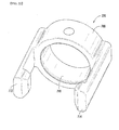
- the end cap 270 includes a circular-shaped body 700, a sealing member 710, and the first and second finger portions 712, 714.
- the circular-shaped body 700 has an inner surface 730 defining an aperture 732 that extends into the circular-shaped body 700 but not completely through the circular-shaped body 700.
- the sealing member 710 is disposed on at least a portion of the inner surface 730 of the circular-shaped body 700.
- the first and second finger portions 712, 714 extend in a first direction from the circular-shaped body 700 that are configured to removably engage first and second notches 422, 421 in the tubular wall 390 such that the inner surface 730 contacts an outer surface of the male connecting portion 470 and the end cap 270 is removably attached to the male connecting portion 470 and the tubular wall 390.
- the first finger portion 712 has an extension portion 740 and a tab portion 742.
- the extension portion 740 extends away from the circular-shaped body 700 in the first direction.
- the tab portion 742 extends away from the extension portion 740 generally perpendicular to the extension portion 740.
- the second finger portion 714 has an extension portion 750 and a tab portion 752.
- the extension portion 750 extends away from the circular-shaped body 700 in the first direction.
- the tab portion 752 extends away from the extension portion 750 generally perpendicular to the extension portion 750.
- the first and second finger portions 712, 714 are centered on a plane that bisects the circular-shaped body 700 into two-equal sized regions, one of which is shown in FIG. 23 .
- the sealing member 710 is constructed of an elastomer, such as at least one of styrene, ethylene, butylene, propylene, and diene for example.
- finger portions 712, 714 constructed of plastic is that the finger portions 712, 714 can be slightly bent when rotating the finger portions 712, 714 about an outer surface of the tubular wall 390 until the finger portions 712, 714 are seated in the notches 422, 421, respectively.
- the manifold assembly 64 directs fluid into heat exchangers in the battery modules 30, 32 for cooling battery cells in the battery modules 30, 32.
- the manifold assembly 66 is provided to receive fluid from outlet ports in the heat exchangers in the battery modules 30, 32 and to route the fluid to the reservoir 60 via the conduit 72.
- the manifold assembly 66 includes manifold members 850, 852, a connecting assembly 854 having a connecting fitting 860 and a retaining member 862, and an end cap 870.
- the manifold members 850, 852 have an identical structure as the manifold members 250, 252, respectively.
- the manifold members 850, 852 are coupled to outlet ports of the heat exchangers in the battery modules 30, 32, respectively.
- the end cap 870 has an identical structure as the end cap 270.
- the battery system and manifold assembly provide a substantial advantage over other systems.
- the battery system and manifold assembly provide a technical effect of utilizing a manifold member and a connecting fitting that be easily removably coupled to each other to form a fluid-tight seal with one another.
- the manifold member can be easily removably coupled to ports of the heat exchangers to form a fluid-tight seal with the heat exchangers.
- the end cap provides a technical effect of being easily coupled to a tubular wall utilizing first and second finger portions and sealing the end of the tubular wall utilizing an internal sealing member.
Landscapes
- Engineering & Computer Science (AREA)
- General Engineering & Computer Science (AREA)
- Manufacturing & Machinery (AREA)
- Chemical & Material Sciences (AREA)
- Chemical Kinetics & Catalysis (AREA)
- Electrochemistry (AREA)
- General Chemical & Material Sciences (AREA)
- Mechanical Engineering (AREA)
- Secondary Cells (AREA)
- Fuel Cell (AREA)
- Battery Mounting, Suspending (AREA)
Abstract
Description
- This application relates generally to a battery system and a manifold assembly therein.
- Battery packs generate heat during usage. To prevent degradation of the battery packs, the battery packs should be cooled. However, existing devices utilized to cool the battery packs are not easily and quickly assembled and coupled to the battery packs.
- Accordingly, the inventor herein has recognized a need for an improved battery system and manifold assembly that eliminates and/or reduces the above mentioned deficiency.
- A manifold assembly in accordance with an exemplary embodiment is provided. The manifold assembly includes a manifold member having a tubular wall with a first end and a second end. The tubular wall further includes an inner surface defining a first central aperture that extends from the first end to the second end. The tubular wall further includes a plurality of apertures extending therethrough. The manifold member further includes a plurality of tubular port members disposed on the tubular wall over the plurality of apertures. The manifold member further includes a first sealing member disposed on the inner surface proximate to the first end, and a male connecting portion extending from the second end. The manifold assembly further includes a connecting fitting having a tubular coupling portion, an abutment ring, and a tubular body. The abutment ring is disposed around an outer surface of the tubular coupling portion a predetermined distance from an end of the tubular coupling portion. The tubular coupling portion is configured to be removably coupled to the first end of the manifold member within the first central aperture such that the first sealing member of the manifold member contacts the outer surface of the tubular coupling portion and the abutment ring abuts against the first end of the manifold member.
- A battery system in accordance with another exemplary embodiment is provided. The battery system includes a plurality of battery cells and a plurality of heat exchangers disposed adjacent to the plurality of battery cells. The battery system further includes a manifold assembly having a manifold member and a connecting fitting. The manifold member fluidly communicates with the plurality of heat exchangers. The manifold member has a tubular wall with a first end and a second end. The tubular wall further includes an inner surface defining a first central aperture that extends from the first end to the second end. The tubular wall further includes a plurality of apertures extending therethrough. The manifold member further includes a plurality of tubular port members disposed on the tubular wall over the plurality of apertures. The manifold member further includes a first sealing member disposed on the inner surface proximate to the first end, and a male connecting portion extending from the second end. The connecting fitting has a tubular coupling portion, an abutment ring, and a tubular body. The abutment ring is disposed around an outer surface of the tubular coupling portion a predetermined distance from an end of the tubular coupling portion. The tubular coupling portion is configured to be removably coupled to the first end of the manifold member within the central aperture such that the first sealing member of the manifold member contacts the outer surface of the tubular coupling portion and the abutment ring abuts against the first end of the manifold member. The plurality of tubular port members of the manifold member are coupled to the plurality of heat exchangers of the plurality of battery cell assemblies.
- An end cap for sealing an end of a tubular wall in accordance with another exemplary embodiment is provided. The end cap includes a circular-shaped body having an inner surface defining an aperture that extends into the circular-shaped body but not completely through the circular-shaped body. The end cap further includes a sealing member disposed on at least a portion of the inner surface of the circular-shaped body. The end cap further includes first and second finger portions extending in a first direction from the circular-shaped body that are configured to removably engage first and second notches in the tubular wall such that the inner surface contacts an outer surface of the tubular wall and the end cap is removably attached to the tubular wall.
-
-
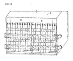
FIG. 1 is a schematic of a portion of a battery system having a battery pack and a cooling system in accordance with an exemplary embodiment; -
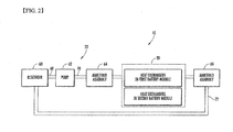
FIG. 2 is a block diagram of the battery system ofFIG. 1 ; -
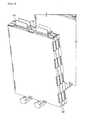
FIG. 3 is an enlarged view of a portion of the battery system ofFIG. 1 ; -
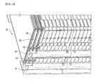
FIG. 4 is another enlarged view of a portion of the battery system ofFIG. 1 illustrating battery cells and heat exchangers therein; -
FIG. 5 is another enlarged view of a portion of the battery system ofFIG. 1 illustrating battery cells therein; -
FIG. 6 is a cross-sectional view of a portion of the battery system ofFIG. 1 illustrating battery cells therein; -
FIG. 7 is a schematic of first and second manifold members utilized in the cooling system ofFIG. 1 ; -
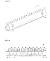
FIG. 8 is a schematic of the first manifold member ofFIG. 7 ; -
FIG. 9 is another schematic of the first manifold member ofFIG. 8 ; -
FIG. 10 is a cross-sectional view of the first manifold member ofFIG. 8 ; -
FIG. 11 is a schematic of a portion of a connecting assembly utilized in the battery system ofFIG. 1 ; -
FIG. 12 is a side view of the connecting assembly ofFIG. 11 utilized in the battery system ofFIG. 1 in accordance with another exemplary embodiment; -
FIG. 13 is a rear view of the connecting assembly ofFIG. 12 ; -
FIG. 14 is a side view of a connecting fitting utilized in the connecting assembly ofFIG. 12 ; -
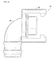
FIG. 15 is a cross-sectional view of a connecting fitting ofFIG. 14 ; -
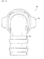
FIG. 16 is another view of the connecting fitting ofFIG. 14 ; -
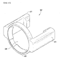
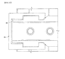
FIG. 17 is a schematic of a retaining member utilized in the connecting assembly ofFIG. 11 ; -
FIG. 18 is a rear view of the retaining member ofFIG. 17 ; -
FIG. 19 is a side view of the retaining member ofFIG. 17 ; -
FIG. 20 is an enlarged schematic of an end cap utilized in the battery system ofFIG. 1 in accordance with another exemplary embodiment; -
FIG. 21 is a cross-sectional view of the end cap ofFIG. 20 ; -
FIG. 22 is another view of the end cap ofFIG. 20 ; -
FIG. 23 is another cross-sectional view of the end cap ofFIG. 20 ; and -
FIG. 24 is a schematic of alternative first and second manifold members that could be utilized in the cooling system ofFIG. 1 . - Referring to
FIGS. 1-4 , abattery system 10 in accordance with an exemplary embodiment is illustrated. Thebattery system 10 includes abattery pack 20 and acooling system 22 for cooling thebattery pack 20. Thebattery pack 20 includesbattery modules battery modules - The
cooling system 22 includes areservoir 60, apump 62, amanifold assembly 64, amanifold assembly 66, andconduits reservoir 60 holds a fluid therein. Thepump 62 pumps the fluid from thereservoir 60 via theconduit 68. Thereafter, thepump 62 pumps the fluid through theconduit 70 into themanifold assembly 64. The fluid flows through themanifold assembly 64 into both a plurality heat exchangers in thebattery module 30 and another plurality heat exchangers in thebattery module 32. Themanifold assembly 66 receives the heated fluid from the heat exchangers in thebattery modules conduit 72 back to thereservoir 60. - Referring to
FIGS. 5 and6 , thebattery module 32 is configured to output an operational voltage that can be utilized to energize a motor of an electric vehicle or a hybrid vehicle. Thebattery module 32 includes a plurality ofbattery cells 100 includingbattery cells heat exchangers 120 includingheat exchangers frame members 150 includingframe members - As shown, the
heat exchanger 122 is disposed between thebattery cells battery cells heat exchanger 122 is disposed between thebattery cells battery cells frame members battery cell 102, theheat exchanger 122, and thebattery cell 104 therebetween. The frame members of 152, 154 are configured to be removably coupled together and to hold thebattery cell 106, theheat exchanger 124, and thebattery cell 108 therebetween. - In one exemplary embodiment, the plurality of
battery cells 100 are rectangular-shaped pouch-type lithium-ion battery cells. Of course, other types of battery cells known to those skilled in the art could be utilized. Since each of the plurality ofbattery cells 100 have a substantially similar structure, only thebattery cell 102 will be described in greater detail for purposes of simplicity. As shown, thebattery cell 102 has a rectangular-shaped pouch-type body 170 andelectrodes body 170. Thebattery cell 102 generates a voltage between theelectrodes - Referring to
FIGS. 4 and6 , the plurality ofheat exchangers 120 have an identical structure to one another. Accordingly, only the structure of theheat exchanger 122 will be described in greater detail below for purposes of simplicity. Theheat exchanger 122 includes a rectangular-shapedbody 190 defining an internal flow path, an inlet port 192 for receiving fluid into thebody 190 from themanifold assembly 64, and anoutlet port 194 for routing fluid from thebody 190 into themanifold assembly 66. In one exemplary embodiment,heat exchangers 120 are constructed of aluminum. In another exemplary embodiment, theheat changers 120 are constructed of stainless steel. Of course, other materials known to those skilled in the art could be utilized to construct theheat exchangers 120. - Referring to
FIG. 1 , themanifold assembly 64 is configured to route cooling fluid into the heat exchangers of thebattery modules manifold assembly 64 includesmanifold members assembly 254 having a connecting fitting 260 and a retainingmember 262, and anend cap 270. - Referring to
FIGS. 1 and7-10 , themanifold member 250 is configured to route fluid into the heat exchangers of thebattery module 30. Themanifold member 250 includes atubular wall 290,tubular port members member 360, and amale connecting portion 370. - The
tubular wall 290 has afirst end 292 and asecond end 294. In one exemplary embodiment, thetubular wall 290 is constructed of a plastic, such as polyethylene or polypropylene for example. Thetubular wall 290 includes aninner surface 297 defining acentral aperture 296 extending a longitudinal length of thetubular wall 290 from thefirst end 292 to thesecond end 294. Thetubular wall 290 also has a plurality ofapertures tubular wall 290 hasnotches - The tubular port members 330-348 are disposed on the
tubular wall 290 over the apertures 300-318, respectively. In one exemplary embodiment, the tubular port members 330-348 are constructed of an elastomer, such as at least one styrene, ethylene, butylene, propylene, and diene for example. Of course, other types of elastomers known to those skilled in the art could be utilized to construct the tubular port members 330-348. The tubular port members 330-348 are further removably coupled to inlet ports on the heat exchangers in thebattery module 30. An advantage of utilizing the tubular port members 330-348 constructed of an elastomer is that the tubular port members 330-348 can be easily removably coupled to the inlet ports of the heat exchangers and forms a fluid-tight seal with the inlet ports. - Referring to
FIGS. 1 ,8 and10 , the sealingmember 360 is disposed on a portion of theinner surface 297 proximate to thefirst end 292. In one exemplary embodiment, the sealingmember 360 is constructed of an elastomer, such as at least one styrene, ethylene, butylene, propylene, and diene for example. Of course, other types of elastomers known to those skilled in the art could be utilized to construct the sealingmember 360. An advantage of utilizing the sealingmember 360 constructed of an elastomer is that the sealingmember 360 can be easily removably coupled to the connecting fitting 260 of the connectingassembly 254 and forms a fluid-tight seal with the connectingfitting 260. - The
male connecting portion 370 extends from thesecond end 294 and is configured to engage themanifold member 252 in order to couple themanifold member 250 to themanifold member 252. Themale connecting portion 370 is constructed of a plastic such as polyethylene or polypropylene for example. - Referring to
FIGS. 1 and7 , themanifold member 252 is coupled to themanifold member 250 and fluidly communicates with themanifold member 250. Themanifold member 252 is configured to route fluid into the heat exchangers of thebattery module 32. Themanifold member 252 advantageously has an identical structure as themanifold member 250 that decreases component costs. Themanifold member 252 includes atubular wall 390,tubular port members member 460, and amale connecting portion 470. - The
tubular wall 390 has afirst end 392 and asecond end 394. In one exemplary embodiment, thetubular wall 390 is constructed of a plastic such as polyethylene or polypropylene for example. Thetubular wall 390 includes aninner surface 398 defining acentral aperture 396 extending a longitudinal length of thetubular wall 390 from thefirst end 392 to thesecond end 394. Thetubular wall 390 also has a plurality ofapertures tubular wall 390 hasnotches FIG. 20 ), and one other notch that is not shown, extending therein. - The tubular port members 430-448 are disposed on the
tubular wall 390 over the apertures 400-418, respectively. In one exemplary embodiment, the tubular port members 430-448 are constructed of an elastomer such as at least one styrene, ethylene, butylene, propylene, and diene for example. Of course, other types of elastomers known to those skilled in the art could be utilized to construct the tubular port members 430-448. The tubular port members 430-448 are further removably coupled with inlet ports on the heat exchangers in thebattery module 32. An advantage of utilizing the tubular port members 430-448 constructed of an elastomer is that the tubular port members 430-448 can be easily removably coupled to the inlet ports of the heat exchangers and form a fluid-tight seal with the inlet ports. - The sealing
member 460 is disposed on a portion of the inner surface 397 proximate to thefirst end 392. In one exemplary embodiment, the sealingmember 460 is constructed of an elastomer such as at least one styrene, ethylene, butylene, propylene, and diene for example. Of course, other types of elastomers known to those skilled in the art could be utilized to construct the sealingmember 460. An advantage of utilizing the sealingmember 460 constructed of an elastomer is that the sealingmember 460 can be easily removably coupled against themale connecting portion 370 of themanifold member 250 to form a fluid-tight seal with themale connecting portion 370. - The
male connecting portion 470 extends from thesecond end 394 and is configured to engage theend cap 270 in order to couple themanifold member 252 to theend cap 270. Themale connecting portion 470 is constructed of a plastic, such as polyethylene or polypropylene for example. - Referring to
FIG. 7 , when coupling themanifold members male connecting portion 370 of themanifold member 250 is removably coupled to thesecond end 392 of themanifold member 252 within thecentral aperture 396 such that the sealingmember 460 of themanifold member 252 contacts an outer surface of themale connecting portion 370 and forms a fluid-tight seal between themanifold members - Referring to
FIG. 24 , in an alternative embodiment, themanifold members manifold members manifold member 850 and themanifold member 250 is that themanifold member 850 has amale connecting portion 870 with a circumferential groove therein that holds an o-ring 872 therein. The o-ring 872 contacts an inner surface of themanifold member 852 to form a fluid-tight seal between themanifold members - Referring to
FIGS. 1 ,2 and11-13 , the connectingassembly 254 is provided to couple to both themanifold member 250 of themanifold assembly 64 and theconduit 70 thus allowing fluid to flow from theconduit 70 through the connectingassembly 254 into themanifold member 250. The connectingassembly 254 includes the connecting fitting 260 and the retainingmember 262. In one exemplary embodiment, the connecting fitting 260 and the retainingmember 262 are constructed from plastic. Of course, in alternative embodiments, the connecting fitting 260 and the retainingmember 262 could be constructed from other materials known to those skilled in the art. - Referring to
FIGS. 1 ,14 and16 , the connecting fitting 260 includes atubular coupling portion 500, anabutment ring 510, and arcuate-shapedtubular body 512, andledges tubular coupling portion 500 includes afirst end 530 and asecond end 532. Thetubular coupling portion 500 further includes acentral aperture 534 extending from thefirst end 530 to thesecond end 532. Theabutment ring 510 is disposed around an outer surface of the tubular coupling portion 500 a predetermined distance from thefirst end 530 of theportion 500. The arcuate-shapedtubular body 512 has afirst end 540 and asecond end 542 and acentral aperture 535 extending from thefirst end 540 to thesecond end 542 that fluidly communicates with thecentral aperture 534. In one exemplary embodiment, the arcuate-shapedtubular body 512 has a 90° bend therein. An advantage of the 90° bend is that conduits disposed relatively close and substantially parallel to an outer surface of thebattery module 30 can be easily coupled to thetubular coupling portion 500 of the connecting fitting 260, which is further coupled to themanifold 250. Of course, in alternative embodiments, thebody 512 could have at another angle or no bend therein. Theledges FIG. 2 ) to form a fluid tight seal with theconduit 70. Theledges tubular body 512 and extend circumferentially around thebody 512. Further, theledge 516 is disposed proximate to thesecond end 542 of thebody 512, and theledge 514 is disposed between theledge 516 and thefirst end 540 of thebody 512. - Referring to
FIGS. 2 ,11 and14 , thetubular coupling portion 500 is disposed in thecentral aperture 296 of thetubular wall 290 of themanifold member 250 and contacts the sealingmember 360 to form a fluid-tight seal. An advantage of this configuration is that the connecting fitting 260 can be rotated within thecentral aperture 296 to a desired angular position for coupling theconduit 70 to the connectingfitting 260. - Referring to
FIGS. 1 ,11-14 and17-19 , the retainingmember 262 is provided to removably couple the connecting fitting 260 on an end of themanifold member 250. The retainingmember 262 has a ring-shapedportion 600 and first andsecond finger portions portion 600. The ring-shapedportion 600 defines acentral aperture 630 therein. The retainingmember 262 further includestabs portion 600 into thecentral aperture 630. Thefirst finger portion 610 has anextension portion 640 and atab portion 642. Theextension portion 640 extends away from the ring-shapedportion 600 in the first direction. Thetab portion 642 extends away from theextension portion 640 generally perpendicular to theextension portion 640. Thesecond finger portion 612 has anextension portion 650 and atab portion 652. Theextension portion 650 extends away from the ring-shapedportion 600 in the first direction. Thetab portion 652 extends away from theextension portion 650 generally perpendicular to theextension portion 650. The ring-shapedportion 600 is slidably disposed on thetubular body 512 of the connecting fitting 254 such that thetubular body 512 is received through thecentral aperture 630 and the ring-shapedportion 600 is slidably disposed against theabutment ring 510. A diameter of thecentral aperture 630 is less than an outer diameter of theabutment ring 500. The first andsecond finger portions notches tubular wall 290 of themanifold member 250 to axially retain the connecting fitting 254 on themanifold member 250. In particular, thetab portions finger portions notches tubular wall 290 of themanifold member 250 to axially retain the connecting fitting 254 on themanifold member 250. In one exemplary embodiment, the retainingmember 262 is constructed of plastic. Of course, other materials known to those skilled in the art could be utilized to construct the retainingmember 262. An advantage of utilizingfinger portions finger portions finger portions tubular wall 290 until thefinger portions notches - Referring to
FIGS. 1 and20-23, theend cap 270 is configured to be coupled to themale connecting portion 470 and theend 294 of thetubular wall 290 of themanifold member 250 to fluidly seal an opening in themale connecting portion 470. In one exemplary embodiment, theend cap 270 is constructed of plastic. Of course, in alternative embodiments, theend cap 270 could be constructed of other materials known to those skilled in the art. Theend cap 270 includes a circular-shapedbody 700, a sealingmember 710, and the first andsecond finger portions body 700 has aninner surface 730 defining anaperture 732 that extends into the circular-shapedbody 700 but not completely through the circular-shapedbody 700. The sealingmember 710 is disposed on at least a portion of theinner surface 730 of the circular-shapedbody 700. The first andsecond finger portions body 700 that are configured to removably engage first andsecond notches tubular wall 390 such that theinner surface 730 contacts an outer surface of themale connecting portion 470 and theend cap 270 is removably attached to themale connecting portion 470 and thetubular wall 390. Thefirst finger portion 712 has anextension portion 740 and atab portion 742. Theextension portion 740 extends away from the circular-shapedbody 700 in the first direction. Thetab portion 742 extends away from theextension portion 740 generally perpendicular to theextension portion 740. Thesecond finger portion 714 has anextension portion 750 and atab portion 752. Theextension portion 750 extends away from the circular-shapedbody 700 in the first direction. Thetab portion 752 extends away from theextension portion 750 generally perpendicular to theextension portion 750. Referring toFIG. 23 , the first andsecond finger portions body 700 into two-equal sized regions, one of which is shown inFIG. 23 . Also, the sealingmember 710 is constructed of an elastomer, such as at least one of styrene, ethylene, butylene, propylene, and diene for example. An advantage of utilizingfinger portions finger portions finger portions tubular wall 390 until thefinger portions notches - Referring to
FIG. 1 , during operation as discussed above, themanifold assembly 64 directs fluid into heat exchangers in thebattery modules battery modules - Referring to
FIGS. 1 and2 , themanifold assembly 66 is provided to receive fluid from outlet ports in the heat exchangers in thebattery modules reservoir 60 via theconduit 72. Themanifold assembly 66 includesmanifold members assembly 854 having a connecting fitting 860 and a retainingmember 862, and anend cap 870. Themanifold members manifold members manifold members battery modules end cap 870 has an identical structure as theend cap 270. - The above-described battery system and manifold assembly provide a substantial advantage over other systems. In particular, the battery system and manifold assembly provide a technical effect of utilizing a manifold member and a connecting fitting that be easily removably coupled to each other to form a fluid-tight seal with one another. Further, the manifold member can be easily removably coupled to ports of the heat exchangers to form a fluid-tight seal with the heat exchangers.
- Also, the end cap provides a technical effect of being easily coupled to a tubular wall utilizing first and second finger portions and sealing the end of the tubular wall utilizing an internal sealing member.
- While the invention has been described with reference to exemplary embodiments, it will be understood by those skilled in the art that various changes may be made and equivalents may be substituted for elements thereof without departing from the scope of the invention. In addition, many modifications may be made to adapt a particular situation or material to the teachings of the invention without departing from the essential scope thereof. Therefore, it is intended that the invention not be limited to the particular embodiment disclosed for carrying this invention, but that the invention will include all embodiments falling within the scope of the appended claims. Moreover, the use of the terms, first, second, etc. are used to distinguish one element from another. Further, the use of the terms a, an, etc. do not denote a limitation of quantity, but rather denote the presence of at least one of the referenced items.
Claims (25)
- A manifold assembly, comprising:a manifold member having a tubular wall with a first end and a second end, the tubular wall further having an inner surface defining a first central aperture that extends from the first end to the second end, the tubular wall further having a plurality of apertures extending therethrough, the manifold member further having a plurality of tubular port members disposed on the tubular wall over the plurality of apertures, the manifold member further having a first sealing member disposed on the inner surface proximate to the first end, and a male connecting portion extending from the second end; anda connecting fitting having a tubular coupling portion, an abutment ring, and a tubular body, the abutment ring being disposed around an outer surface of the tubular coupling portion a predetermined distance from an end of the tubular coupling portion, the tubular coupling portion configured to be removably coupled to the first end of the manifold member within the first central aperture such that the first sealing member of the manifold member contacts the outer surface of the tubular coupling portion and the abutment ring abuts against the first end of the manifold member.
- The manifold assembly of claim 1, wherein the tubular body of the connecting fitting is an arcuate-shaped tubular body.
- The manifold assembly of claim 2, wherein the arcuate-shaped tubular body has a 90 degree bend therein.
- The manifold assembly of claim 1, wherein the tubular body of the connecting fitting has first and second circumferentially disposed ledges extending outwardly from an outer surface of the tubular body.
- The manifold assembly of claim 1, further comprising a retaining member configured to removably hold the connecting fitting on the first end of the manifold member.
- The manifold assembly of claim 5, wherein the retaining member has a ring-shaped portion and first and second finger portions extending in a first direction from the ring-shaped portion, the ring-shaped portion defining a second central aperture, the ring-shaped portion being slidably disposed on the tubular body of the connecting fitting such that the tubular body is received through the second central aperture and the ring-shaped portion is slidably disposed against the abutment ring, a diameter of the second central aperture being less than a diameter of the abutment ring, the first and second finger portions configured to removably engage first and second notches, respectively, in the tubular wall of the manifold member to fixedly hold the connecting fitting on the manifold member.
- The manifold assembly of claim 1, further comprising an end cap configured to be removably coupled to the male connecting portion of the manifold member.
- The manifold assembly of claim 7, wherein the end cap comprises:a circular-shaped body having an inner surface defining an aperture that extends into the circular-shaped body but not completely through the circular-shaped body;a second sealing member disposed on at least a portion of the inner surface of the circular-shaped body; andfirst and second finger portions extending in a first direction from the circular-shaped body configured to removably engage first and second notches, respectively, in the tubular wall of the manifold member, and the inner surface of the circular-shaped body is configured to receive the male connecting portion of the manifold member therein, and the second sealing member configured to contact an outer surface of the male connecting portion.
- The manifold assembly of claim 1, wherein the tubular wall of the manifold assembly is constructed of plastic.
- The manifold assembly of claim 9, wherein the plastic is at least one of polyethylene and polypropylene.
- The manifold assembly of claim 1, wherein the plurality of tubular port members of the manifold member are constructed of an elastomer.
- The manifold assembly of claim 11, wherein the elastomer is at least one of styrene, ethylene, butylene, propylene, and diene.
- The manifold assembly of claim 1, wherein the connecting fitting is constructed of plastic.
- A battery system, comprising:a plurality of battery cells and a plurality of heat exchangers disposed adjacent to the plurality of battery cells;a manifold assembly having a manifold member and a connecting fitting, the manifold member fluidly communicating with the plurality of heat exchangers;the manifold member having a tubular wall with a first end and a second end, the tubular wall further having an inner surface defining a first central aperture that extends from the first end to the second end, the tubular wall further having a plurality of apertures extending therethrough, the manifold member further having a plurality of tubular port members disposed on the tubular wall over the plurality of apertures, the manifold member further having a first sealing member disposed on the inner surface proximate to the first end, and a male connecting portion extending from the second end;the connecting fitting having a tubular coupling portion, an abutment ring, and a tubular body, the abutment ring being disposed around an outer surface of the tubular coupling portion a predetermined distance from an end of the tubular coupling portion, the tubular coupling portion configured to be removably coupled to the first end of the manifold member within the first central aperture such that the first sealing member of the manifold member contacts the outer surface of the tubular coupling portion and the abutment ring abuts against the first end of the manifold member; andthe plurality of tubular port members of the manifold member being coupled to the plurality of heat exchangers of the plurality of battery cell assemblies.
- The battery system of claim 14, wherein the tubular body of the connecting fitting is an arcuate-shaped tubular body.
- The battery system of claim 15, wherein the arcuate-shaped tubular body of the connecting fitting has a 90 degree bend therein.
- The battery system of claim 14, wherein the tubular body of the connecting fitting has first and second circumferentially disposed ledges extending outwardly from an outer surface of the tubular body.
- The battery system of claim 14, further comprising a retaining member configured to removably hold the connecting fitting on the first end of the manifold member.
- The battery system of claim 18, wherein the retaining member has a ring-shaped portion and first and second finger portions extending in a first direction from the ring-shaped portion, the ring-shaped portion defining a second central aperture, the tubular body of the connecting fitting being received through the second central aperture of the ring-shaped portion, such that the ring-shaped portion is slidably disposed on the tubular body of the connecting fitting and is further slidably disposed against the abutment ring, a diameter of the second central aperture being less than a diameter of the abutment ring, the first and second finger portions configured to removably engage first and second notches, respectively, in the tubular wall of the manifold member to fixedly hold the connecting fitting on the manifold member.
- The battery system of claim 14, further comprising an end cap configured to be removably coupled to the male connecting portion of the manifold member.
- An end cap for sealing an end of a tubular wall, comprising:a circular-shaped body having an inner surface defining an aperture that extends into the circular-shaped body but not completely through the circular-shaped body;a second sealing member disposed on at least a portion of the inner surface of the circular-shaped body; andfirst and second finger portions extending in a first direction from the circular-shaped body that are configured to removably engage first and second notches in the tubular wall such that the inner surface contacts an outer surface of the tubular wall and the end cap is removably attached to the tubular wall.
- The end cap of claim 21, wherein the first finger portion has a first extension portion and a first tab portion, the first extension portion extending away from the circular-shaped body in the first direction, the first tab portion extending away from the first extension portion perpendicular to the first extension portion.
- The end cap of claim 21, wherein the first and second finger portions are centered on a plane that bisects the circular-shaped body into two-equal sized regions.
- The end cap of claim 21, wherein the sealing member is constructed of an elastomer.
- The end cap of claim 24, wherein the elastomer is at least one of styrene, ethylene, butylene, propylene, and diene.
Priority Applications (1)
| Application Number | Priority Date | Filing Date | Title |
|---|---|---|---|
| PL11820118T PL2610947T3 (en) | 2010-08-23 | 2011-08-10 | Battery system including a manifold member and a connection fitting, and manifold assembly |
Applications Claiming Priority (3)
| Application Number | Priority Date | Filing Date | Title |
|---|---|---|---|
| US12/861,381 US8353315B2 (en) | 2010-08-23 | 2010-08-23 | End cap |
| US12/861,375 US8920956B2 (en) | 2010-08-23 | 2010-08-23 | Battery system and manifold assembly having a manifold member and a connecting fitting |
| PCT/KR2011/005822 WO2012026690A2 (en) | 2010-08-23 | 2011-08-10 | Battery system including a manifold member and a connection fitting, and manifold assembly |
Publications (3)
| Publication Number | Publication Date |
|---|---|
| EP2610947A2 true EP2610947A2 (en) | 2013-07-03 |
| EP2610947A4 EP2610947A4 (en) | 2016-11-02 |
| EP2610947B1 EP2610947B1 (en) | 2018-11-21 |
Family
ID=45723890
Family Applications (1)
| Application Number | Title | Priority Date | Filing Date |
|---|---|---|---|
| EP11820118.5A Active EP2610947B1 (en) | 2010-08-23 | 2011-08-10 | Battery system including a manifold member and a connection fitting, and manifold assembly |
Country Status (4)
| Country | Link |
|---|---|
| EP (1) | EP2610947B1 (en) |
| CN (1) | CN103098262B (en) |
| PL (1) | PL2610947T3 (en) |
| WO (1) | WO2012026690A2 (en) |
Cited By (8)
| Publication number | Priority date | Publication date | Assignee | Title |
|---|---|---|---|---|
| FR3001341A1 (en) * | 2013-01-24 | 2014-07-25 | Valeo Systemes Thermiques | Battery assembly for use in regulating circuit utilized in cooling loop of heating, ventilation and air-conditioning installation of e.g. electric car, has ring deformed in steady position in which ring exerts restraint stress on pipes |
| EP3522291A1 (en) * | 2018-01-31 | 2019-08-07 | Samsung SDI Co., Ltd. | Tube assembly for a fluid distribution system of a battery pack of a vehicle and battery pack for a vehicle |
| EP3528336A4 (en) * | 2016-10-13 | 2020-05-27 | Samsung SDI Co., Ltd | BATTERY MODULE |
| CN111699337A (en) * | 2018-01-31 | 2020-09-22 | 三星Sdi株式会社 | Tube assembly for a fluid distribution system of a vehicle battery pack and battery pack for a vehicle |
| DE102021117490A1 (en) | 2021-07-07 | 2023-01-12 | Dr. Ing. H.C. F. Porsche Aktiengesellschaft | Connection device for providing a media connection on a component and arrangement |
| US11949077B2 (en) | 2016-10-17 | 2024-04-02 | Samsung Sdi Co., Ltd. | Battery module |
| FR3147857A1 (en) * | 2023-04-13 | 2024-10-18 | Valeo Systemes Thermiques | Thermal regulation device |
| EP4468463A4 (en) * | 2022-12-28 | 2025-04-30 | LG Energy Solution, Ltd. | BATTERY PACK AND VEHICLE WITH IT |
Families Citing this family (8)
| Publication number | Priority date | Publication date | Assignee | Title |
|---|---|---|---|---|
| CN105764306B (en) * | 2016-04-08 | 2018-03-06 | 华为技术有限公司 | Blindmate manifold system and liquid cooling system |
| US20180123201A1 (en) * | 2016-10-28 | 2018-05-03 | Inevit, Llc | Battery module cooling tube including an integrated turbulator component and method thereof |
| CN208738329U (en) * | 2018-09-21 | 2019-04-12 | 宁德时代新能源科技股份有限公司 | a battery pack |
| CN112072046B (en) * | 2020-10-19 | 2022-12-27 | 江苏时代新能源科技有限公司 | Battery, electric device, method and equipment for preparing battery |
| WO2022082394A1 (en) | 2020-10-19 | 2022-04-28 | 江苏时代新能源科技有限公司 | Battery, power consuming device and method and apparatus for producing battery |
| CN112610778B (en) * | 2020-12-18 | 2024-08-27 | 珠海格力电器股份有限公司 | Waterway plate and water purifying and drinking machine |
| CN114552113B (en) * | 2022-04-26 | 2022-07-19 | 南通龙海电子科技有限公司 | Battery management equipment for new energy automobile |
| WO2025119564A1 (en) * | 2023-12-05 | 2025-06-12 | Voss Automotive Gmbh | Modular fluid distributing system |
Family Cites Families (23)
| Publication number | Priority date | Publication date | Assignee | Title |
|---|---|---|---|---|
| US2550591A (en) * | 1948-10-15 | 1951-04-24 | Malcolm W Fraser | Tube fitting assembly |
| US2949205A (en) * | 1958-09-02 | 1960-08-16 | Jr Harold C Fitz | Bottle cap |
| US3603621A (en) * | 1969-10-27 | 1971-09-07 | Frederick L Parsons | Hose coupling |
| JPS57176994U (en) * | 1981-05-06 | 1982-11-09 | ||
| US4706737A (en) * | 1986-11-20 | 1987-11-17 | International Fuel Cells Corporation | Fuel cell coolant inlet manifold and system |
| JPH037671Y2 (en) * | 1987-04-30 | 1991-02-26 | ||
| US4730856A (en) * | 1987-05-28 | 1988-03-15 | Usui Kokusai Sangyo Kabushika Kaisha | Pipe joint for connecting a pipe having a small diameter |
| US5046765A (en) * | 1988-05-31 | 1991-09-10 | Usui International Industry Ltd. | Tubular fitting for connection of a branch pipe |
| DE4129397C1 (en) * | 1991-09-04 | 1993-03-11 | Rasmussen Gmbh, 6457 Maintal, De | |
| JP4124860B2 (en) * | 1998-06-18 | 2008-07-23 | 東京瓦斯株式会社 | header |
| DE29901962U1 (en) * | 1999-02-05 | 1999-04-22 | Böhm Kunststoffe GmbH, 95158 Kirchenlamitz | Closure for pipes |
| JP2001032985A (en) * | 1999-07-21 | 2001-02-06 | Tokyo Gas Co Ltd | Piping fitting |
| FR2801569B1 (en) * | 1999-11-29 | 2002-04-26 | Valois Sa | SAFETY CAP |
| US6295980B1 (en) * | 2000-01-12 | 2001-10-02 | Pacfab, Inc. | Composite polymer manifold for water heating unit |
| JP2002089769A (en) * | 2000-09-19 | 2002-03-27 | Toto Ltd | Water feeding header |
| DE10130369A1 (en) * | 2001-06-23 | 2003-01-02 | Behr Gmbh & Co | Device for cooling a vehicle device, in particular battery or fuel cell |
| JP2004183761A (en) * | 2002-12-03 | 2004-07-02 | Ck Kinzoku Kk | Hot water/cold water supplying pipe header and joint |
| JP2006266341A (en) * | 2005-03-22 | 2006-10-05 | Matsushita Electric Works Ltd | Pipe connection structure, header, member for branching, fixing member, and end cap |
| US20070087266A1 (en) * | 2005-10-18 | 2007-04-19 | Debbi Bourke | Modular battery system |
| US7846573B2 (en) * | 2007-06-01 | 2010-12-07 | Cobasys, Llc | Coolant manifold |
| JP4568316B2 (en) * | 2007-09-28 | 2010-10-27 | 井上スダレ株式会社 | header |
| US9140501B2 (en) * | 2008-06-30 | 2015-09-22 | Lg Chem, Ltd. | Battery module having a rubber cooling manifold |
| CN102257652B (en) * | 2008-11-12 | 2014-04-02 | 江森自控帅福得先进能源动力系统有限责任公司 | Battery system with heat exchanger |
-
2011
- 2011-08-10 PL PL11820118T patent/PL2610947T3/en unknown
- 2011-08-10 EP EP11820118.5A patent/EP2610947B1/en active Active
- 2011-08-10 WO PCT/KR2011/005822 patent/WO2012026690A2/en not_active Ceased
- 2011-08-10 CN CN201180040586.9A patent/CN103098262B/en active Active
Cited By (11)
| Publication number | Priority date | Publication date | Assignee | Title |
|---|---|---|---|---|
| FR3001341A1 (en) * | 2013-01-24 | 2014-07-25 | Valeo Systemes Thermiques | Battery assembly for use in regulating circuit utilized in cooling loop of heating, ventilation and air-conditioning installation of e.g. electric car, has ring deformed in steady position in which ring exerts restraint stress on pipes |
| EP3528336A4 (en) * | 2016-10-13 | 2020-05-27 | Samsung SDI Co., Ltd | BATTERY MODULE |
| US11749853B2 (en) | 2016-10-13 | 2023-09-05 | Samsung Sdi Co., Ltd. | Battery module |
| US11949077B2 (en) | 2016-10-17 | 2024-04-02 | Samsung Sdi Co., Ltd. | Battery module |
| EP3522291A1 (en) * | 2018-01-31 | 2019-08-07 | Samsung SDI Co., Ltd. | Tube assembly for a fluid distribution system of a battery pack of a vehicle and battery pack for a vehicle |
| CN111699337A (en) * | 2018-01-31 | 2020-09-22 | 三星Sdi株式会社 | Tube assembly for a fluid distribution system of a vehicle battery pack and battery pack for a vehicle |
| DE102021117490A1 (en) | 2021-07-07 | 2023-01-12 | Dr. Ing. H.C. F. Porsche Aktiengesellschaft | Connection device for providing a media connection on a component and arrangement |
| DE102021117490B4 (en) | 2021-07-07 | 2023-03-23 | Dr. Ing. H.C. F. Porsche Aktiengesellschaft | Connection device for providing a media connection on a component and arrangement |
| EP4468463A4 (en) * | 2022-12-28 | 2025-04-30 | LG Energy Solution, Ltd. | BATTERY PACK AND VEHICLE WITH IT |
| JP2025515854A (en) * | 2022-12-28 | 2025-05-20 | エルジー エナジー ソリューション リミテッド | Battery pack and automobile including same |
| FR3147857A1 (en) * | 2023-04-13 | 2024-10-18 | Valeo Systemes Thermiques | Thermal regulation device |
Also Published As
| Publication number | Publication date |
|---|---|
| EP2610947A4 (en) | 2016-11-02 |
| CN103098262B (en) | 2015-11-25 |
| WO2012026690A3 (en) | 2012-05-10 |
| EP2610947B1 (en) | 2018-11-21 |
| CN103098262A (en) | 2013-05-08 |
| WO2012026690A2 (en) | 2012-03-01 |
| PL2610947T3 (en) | 2019-05-31 |
Similar Documents
| Publication | Publication Date | Title |
|---|---|---|
| US8920956B2 (en) | Battery system and manifold assembly having a manifold member and a connecting fitting | |
| EP2610947B1 (en) | Battery system including a manifold member and a connection fitting, and manifold assembly | |
| EP2610948B1 (en) | Battery system, and manifold assembly comprising two separably coupled manifold members | |
| EP2610941B1 (en) | Connecting assembly | |
| US8353315B2 (en) | End cap | |
| US8734975B2 (en) | Modular fluid transport system | |
| US7883793B2 (en) | Battery module having battery cell assemblies with alignment-coupling features | |
| US9140501B2 (en) | Battery module having a rubber cooling manifold | |
| US9281547B2 (en) | Traction battery thermal management system | |
| EP2887423A1 (en) | Battery module | |
| US9444124B2 (en) | Battery cell assembly and method for coupling a cooling fin to first and second cooling manifolds | |
| CN111276774A (en) | battery module | |
| WO2013105756A1 (en) | Secondary battery module and secondary battery pack | |
| CN111276652A (en) | battery module | |
| CA3150318C (en) | Lic module |
Legal Events
| Date | Code | Title | Description |
|---|---|---|---|
| PUAI | Public reference made under article 153(3) epc to a published international application that has entered the european phase |
Free format text: ORIGINAL CODE: 0009012 |
|
| 17P | Request for examination filed |
Effective date: 20130220 |
|
| AK | Designated contracting states |
Kind code of ref document: A2 Designated state(s): AL AT BE BG CH CY CZ DE DK EE ES FI FR GB GR HR HU IE IS IT LI LT LU LV MC MK MT NL NO PL PT RO RS SE SI SK SM TR |
|
| DAX | Request for extension of the european patent (deleted) | ||
| RIC1 | Information provided on ipc code assigned before grant |
Ipc: F16L 41/03 20060101AFI20160623BHEP Ipc: H01M 10/6568 20140101ALI20160623BHEP Ipc: H01M 10/613 20140101ALI20160623BHEP Ipc: F16L 55/115 20060101ALI20160623BHEP Ipc: F16L 37/098 20060101ALI20160623BHEP |
|
| REG | Reference to a national code |
Ref country code: DE Ref legal event code: R079 Ref document number: 602011054153 Country of ref document: DE Free format text: PREVIOUS MAIN CLASS: H01M0002400000 Ipc: F16L0041030000 |
|
| A4 | Supplementary search report drawn up and despatched |
Effective date: 20161005 |
|
| RIC1 | Information provided on ipc code assigned before grant |
Ipc: F16L 37/098 20060101ALI20160928BHEP Ipc: F16L 55/115 20060101ALI20160928BHEP Ipc: H01M 10/6568 20140101ALI20160928BHEP Ipc: H01M 10/613 20140101ALI20160928BHEP Ipc: F16L 41/03 20060101AFI20160928BHEP |
|
| STAA | Information on the status of an ep patent application or granted ep patent |
Free format text: STATUS: EXAMINATION IS IN PROGRESS |
|
| 17Q | First examination report despatched |
Effective date: 20170719 |
|
| GRAP | Despatch of communication of intention to grant a patent |
Free format text: ORIGINAL CODE: EPIDOSNIGR1 |
|
| STAA | Information on the status of an ep patent application or granted ep patent |
Free format text: STATUS: GRANT OF PATENT IS INTENDED |
|
| RAP1 | Party data changed (applicant data changed or rights of an application transferred) |
Owner name: LG CHEM, LTD. |
|
| INTG | Intention to grant announced |
Effective date: 20180912 |
|
| GRAS | Grant fee paid |
Free format text: ORIGINAL CODE: EPIDOSNIGR3 |
|
| GRAA | (expected) grant |
Free format text: ORIGINAL CODE: 0009210 |
|
| STAA | Information on the status of an ep patent application or granted ep patent |
Free format text: STATUS: THE PATENT HAS BEEN GRANTED |
|
| AK | Designated contracting states |
Kind code of ref document: B1 Designated state(s): AL AT BE BG CH CY CZ DE DK EE ES FI FR GB GR HR HU IE IS IT LI LT LU LV MC MK MT NL NO PL PT RO RS SE SI SK SM TR |
|
| REG | Reference to a national code |
Ref country code: CH Ref legal event code: EP |
|
| REG | Reference to a national code |
Ref country code: IE Ref legal event code: FG4D |
|
| REG | Reference to a national code |
Ref country code: DE Ref legal event code: R096 Ref document number: 602011054153 Country of ref document: DE |
|
| REG | Reference to a national code |
Ref country code: AT Ref legal event code: REF Ref document number: 1067943 Country of ref document: AT Kind code of ref document: T Effective date: 20181215 |
|
| REG | Reference to a national code |
Ref country code: NL Ref legal event code: MP Effective date: 20181121 |
|
| REG | Reference to a national code |
Ref country code: AT Ref legal event code: MK05 Ref document number: 1067943 Country of ref document: AT Kind code of ref document: T Effective date: 20181121 |
|
| PG25 | Lapsed in a contracting state [announced via postgrant information from national office to epo] |
Ref country code: BG Free format text: LAPSE BECAUSE OF FAILURE TO SUBMIT A TRANSLATION OF THE DESCRIPTION OR TO PAY THE FEE WITHIN THE PRESCRIBED TIME-LIMIT Effective date: 20190221 Ref country code: FI Free format text: LAPSE BECAUSE OF FAILURE TO SUBMIT A TRANSLATION OF THE DESCRIPTION OR TO PAY THE FEE WITHIN THE PRESCRIBED TIME-LIMIT Effective date: 20181121 Ref country code: IS Free format text: LAPSE BECAUSE OF FAILURE TO SUBMIT A TRANSLATION OF THE DESCRIPTION OR TO PAY THE FEE WITHIN THE PRESCRIBED TIME-LIMIT Effective date: 20190321 Ref country code: NO Free format text: LAPSE BECAUSE OF FAILURE TO SUBMIT A TRANSLATION OF THE DESCRIPTION OR TO PAY THE FEE WITHIN THE PRESCRIBED TIME-LIMIT Effective date: 20190221 Ref country code: HR Free format text: LAPSE BECAUSE OF FAILURE TO SUBMIT A TRANSLATION OF THE DESCRIPTION OR TO PAY THE FEE WITHIN THE PRESCRIBED TIME-LIMIT Effective date: 20181121 Ref country code: LT Free format text: LAPSE BECAUSE OF FAILURE TO SUBMIT A TRANSLATION OF THE DESCRIPTION OR TO PAY THE FEE WITHIN THE PRESCRIBED TIME-LIMIT Effective date: 20181121 Ref country code: ES Free format text: LAPSE BECAUSE OF FAILURE TO SUBMIT A TRANSLATION OF THE DESCRIPTION OR TO PAY THE FEE WITHIN THE PRESCRIBED TIME-LIMIT Effective date: 20181121 Ref country code: LV Free format text: LAPSE BECAUSE OF FAILURE TO SUBMIT A TRANSLATION OF THE DESCRIPTION OR TO PAY THE FEE WITHIN THE PRESCRIBED TIME-LIMIT Effective date: 20181121 Ref country code: AT Free format text: LAPSE BECAUSE OF FAILURE TO SUBMIT A TRANSLATION OF THE DESCRIPTION OR TO PAY THE FEE WITHIN THE PRESCRIBED TIME-LIMIT Effective date: 20181121 |
|
| PG25 | Lapsed in a contracting state [announced via postgrant information from national office to epo] |
Ref country code: AL Free format text: LAPSE BECAUSE OF FAILURE TO SUBMIT A TRANSLATION OF THE DESCRIPTION OR TO PAY THE FEE WITHIN THE PRESCRIBED TIME-LIMIT Effective date: 20181121 Ref country code: RS Free format text: LAPSE BECAUSE OF FAILURE TO SUBMIT A TRANSLATION OF THE DESCRIPTION OR TO PAY THE FEE WITHIN THE PRESCRIBED TIME-LIMIT Effective date: 20181121 Ref country code: SE Free format text: LAPSE BECAUSE OF FAILURE TO SUBMIT A TRANSLATION OF THE DESCRIPTION OR TO PAY THE FEE WITHIN THE PRESCRIBED TIME-LIMIT Effective date: 20181121 Ref country code: NL Free format text: LAPSE BECAUSE OF FAILURE TO SUBMIT A TRANSLATION OF THE DESCRIPTION OR TO PAY THE FEE WITHIN THE PRESCRIBED TIME-LIMIT Effective date: 20181121 Ref country code: GR Free format text: LAPSE BECAUSE OF FAILURE TO SUBMIT A TRANSLATION OF THE DESCRIPTION OR TO PAY THE FEE WITHIN THE PRESCRIBED TIME-LIMIT Effective date: 20190222 Ref country code: PT Free format text: LAPSE BECAUSE OF FAILURE TO SUBMIT A TRANSLATION OF THE DESCRIPTION OR TO PAY THE FEE WITHIN THE PRESCRIBED TIME-LIMIT Effective date: 20190321 |
|
| PG25 | Lapsed in a contracting state [announced via postgrant information from national office to epo] |
Ref country code: IT Free format text: LAPSE BECAUSE OF FAILURE TO SUBMIT A TRANSLATION OF THE DESCRIPTION OR TO PAY THE FEE WITHIN THE PRESCRIBED TIME-LIMIT Effective date: 20181121 Ref country code: DK Free format text: LAPSE BECAUSE OF FAILURE TO SUBMIT A TRANSLATION OF THE DESCRIPTION OR TO PAY THE FEE WITHIN THE PRESCRIBED TIME-LIMIT Effective date: 20181121 Ref country code: CZ Free format text: LAPSE BECAUSE OF FAILURE TO SUBMIT A TRANSLATION OF THE DESCRIPTION OR TO PAY THE FEE WITHIN THE PRESCRIBED TIME-LIMIT Effective date: 20181121 |
|
| REG | Reference to a national code |
Ref country code: DE Ref legal event code: R097 Ref document number: 602011054153 Country of ref document: DE |
|
| PG25 | Lapsed in a contracting state [announced via postgrant information from national office to epo] |
Ref country code: SK Free format text: LAPSE BECAUSE OF FAILURE TO SUBMIT A TRANSLATION OF THE DESCRIPTION OR TO PAY THE FEE WITHIN THE PRESCRIBED TIME-LIMIT Effective date: 20181121 Ref country code: RO Free format text: LAPSE BECAUSE OF FAILURE TO SUBMIT A TRANSLATION OF THE DESCRIPTION OR TO PAY THE FEE WITHIN THE PRESCRIBED TIME-LIMIT Effective date: 20181121 Ref country code: EE Free format text: LAPSE BECAUSE OF FAILURE TO SUBMIT A TRANSLATION OF THE DESCRIPTION OR TO PAY THE FEE WITHIN THE PRESCRIBED TIME-LIMIT Effective date: 20181121 Ref country code: SM Free format text: LAPSE BECAUSE OF FAILURE TO SUBMIT A TRANSLATION OF THE DESCRIPTION OR TO PAY THE FEE WITHIN THE PRESCRIBED TIME-LIMIT Effective date: 20181121 |
|
| PLBE | No opposition filed within time limit |
Free format text: ORIGINAL CODE: 0009261 |
|
| STAA | Information on the status of an ep patent application or granted ep patent |
Free format text: STATUS: NO OPPOSITION FILED WITHIN TIME LIMIT |
|
| 26N | No opposition filed |
Effective date: 20190822 |
|
| PG25 | Lapsed in a contracting state [announced via postgrant information from national office to epo] |
Ref country code: SI Free format text: LAPSE BECAUSE OF FAILURE TO SUBMIT A TRANSLATION OF THE DESCRIPTION OR TO PAY THE FEE WITHIN THE PRESCRIBED TIME-LIMIT Effective date: 20181121 |
|
| PG25 | Lapsed in a contracting state [announced via postgrant information from national office to epo] |
Ref country code: TR Free format text: LAPSE BECAUSE OF FAILURE TO SUBMIT A TRANSLATION OF THE DESCRIPTION OR TO PAY THE FEE WITHIN THE PRESCRIBED TIME-LIMIT Effective date: 20181121 |
|
| PG25 | Lapsed in a contracting state [announced via postgrant information from national office to epo] |
Ref country code: MC Free format text: LAPSE BECAUSE OF FAILURE TO SUBMIT A TRANSLATION OF THE DESCRIPTION OR TO PAY THE FEE WITHIN THE PRESCRIBED TIME-LIMIT Effective date: 20181121 Ref country code: LU Free format text: LAPSE BECAUSE OF NON-PAYMENT OF DUE FEES Effective date: 20190810 Ref country code: CH Free format text: LAPSE BECAUSE OF NON-PAYMENT OF DUE FEES Effective date: 20190831 Ref country code: LI Free format text: LAPSE BECAUSE OF NON-PAYMENT OF DUE FEES Effective date: 20190831 |
|
| REG | Reference to a national code |
Ref country code: BE Ref legal event code: MM Effective date: 20190831 |
|
| PG25 | Lapsed in a contracting state [announced via postgrant information from national office to epo] |
Ref country code: IE Free format text: LAPSE BECAUSE OF NON-PAYMENT OF DUE FEES Effective date: 20190810 |
|
| PG25 | Lapsed in a contracting state [announced via postgrant information from national office to epo] |
Ref country code: BE Free format text: LAPSE BECAUSE OF NON-PAYMENT OF DUE FEES Effective date: 20190831 |
|
| PG25 | Lapsed in a contracting state [announced via postgrant information from national office to epo] |
Ref country code: CY Free format text: LAPSE BECAUSE OF FAILURE TO SUBMIT A TRANSLATION OF THE DESCRIPTION OR TO PAY THE FEE WITHIN THE PRESCRIBED TIME-LIMIT Effective date: 20181121 |
|
| PG25 | Lapsed in a contracting state [announced via postgrant information from national office to epo] |
Ref country code: MT Free format text: LAPSE BECAUSE OF FAILURE TO SUBMIT A TRANSLATION OF THE DESCRIPTION OR TO PAY THE FEE WITHIN THE PRESCRIBED TIME-LIMIT Effective date: 20181121 Ref country code: HU Free format text: LAPSE BECAUSE OF FAILURE TO SUBMIT A TRANSLATION OF THE DESCRIPTION OR TO PAY THE FEE WITHIN THE PRESCRIBED TIME-LIMIT; INVALID AB INITIO Effective date: 20110810 |
|
| PG25 | Lapsed in a contracting state [announced via postgrant information from national office to epo] |
Ref country code: MK Free format text: LAPSE BECAUSE OF FAILURE TO SUBMIT A TRANSLATION OF THE DESCRIPTION OR TO PAY THE FEE WITHIN THE PRESCRIBED TIME-LIMIT Effective date: 20181121 |
|
| P01 | Opt-out of the competence of the unified patent court (upc) registered |
Effective date: 20230408 |
|
| REG | Reference to a national code |
Ref country code: DE Ref legal event code: R081 Ref document number: 602011054153 Country of ref document: DE Owner name: LG ENERGY SOLUTION, LTD., KR Free format text: FORMER OWNER: LG CHEM, LTD., SEOUL, KR |
|
| REG | Reference to a national code |
Ref country code: GB Ref legal event code: 732E Free format text: REGISTERED BETWEEN 20230824 AND 20230831 |
|
| PGFP | Annual fee paid to national office [announced via postgrant information from national office to epo] |
Ref country code: DE Payment date: 20250721 Year of fee payment: 15 |
|
| PGFP | Annual fee paid to national office [announced via postgrant information from national office to epo] |
Ref country code: PL Payment date: 20250723 Year of fee payment: 15 |
|
| PGFP | Annual fee paid to national office [announced via postgrant information from national office to epo] |
Ref country code: GB Payment date: 20250722 Year of fee payment: 15 |
|
| PGFP | Annual fee paid to national office [announced via postgrant information from national office to epo] |
Ref country code: FR Payment date: 20250725 Year of fee payment: 15 |