EP2610679A2 - Image forming apparatus - Google Patents
Image forming apparatus Download PDFInfo
- Publication number
- EP2610679A2 EP2610679A2 EP20120184908 EP12184908A EP2610679A2 EP 2610679 A2 EP2610679 A2 EP 2610679A2 EP 20120184908 EP20120184908 EP 20120184908 EP 12184908 A EP12184908 A EP 12184908A EP 2610679 A2 EP2610679 A2 EP 2610679A2
- Authority
- EP
- European Patent Office
- Prior art keywords
- image forming
- window
- shutter
- forming apparatus
- disposed
- Prior art date
- Legal status (The legal status is an assumption and is not a legal conclusion. Google has not performed a legal analysis and makes no representation as to the accuracy of the status listed.)
- Granted
Links
Images






Classifications
-
- G—PHYSICS
- G03—PHOTOGRAPHY; CINEMATOGRAPHY; ANALOGOUS TECHNIQUES USING WAVES OTHER THAN OPTICAL WAVES; ELECTROGRAPHY; HOLOGRAPHY
- G03G—ELECTROGRAPHY; ELECTROPHOTOGRAPHY; MAGNETOGRAPHY
- G03G15/00—Apparatus for electrographic processes using a charge pattern
- G03G15/04—Apparatus for electrographic processes using a charge pattern for exposing, i.e. imagewise exposure by optically projecting the original image on a photoconductive recording material
- G03G15/043—Apparatus for electrographic processes using a charge pattern for exposing, i.e. imagewise exposure by optically projecting the original image on a photoconductive recording material with means for controlling illumination or exposure
- G03G15/0435—Apparatus for electrographic processes using a charge pattern for exposing, i.e. imagewise exposure by optically projecting the original image on a photoconductive recording material with means for controlling illumination or exposure by introducing an optical element in the optical path, e.g. a filter
-
- G—PHYSICS
- G03—PHOTOGRAPHY; CINEMATOGRAPHY; ANALOGOUS TECHNIQUES USING WAVES OTHER THAN OPTICAL WAVES; ELECTROGRAPHY; HOLOGRAPHY
- G03G—ELECTROGRAPHY; ELECTROPHOTOGRAPHY; MAGNETOGRAPHY
- G03G21/00—Arrangements not provided for by groups G03G13/00 - G03G19/00, e.g. cleaning, elimination of residual charge
- G03G21/10—Collecting or recycling waste developer
-
- G—PHYSICS
- G03—PHOTOGRAPHY; CINEMATOGRAPHY; ANALOGOUS TECHNIQUES USING WAVES OTHER THAN OPTICAL WAVES; ELECTROGRAPHY; HOLOGRAPHY
- G03G—ELECTROGRAPHY; ELECTROPHOTOGRAPHY; MAGNETOGRAPHY
- G03G21/00—Arrangements not provided for by groups G03G13/00 - G03G19/00, e.g. cleaning, elimination of residual charge
- G03G21/16—Mechanical means for facilitating the maintenance of the apparatus, e.g. modular arrangements
- G03G21/1604—Arrangement or disposition of the entire apparatus
- G03G21/1623—Means to access the interior of the apparatus
- G03G21/1633—Means to access the interior of the apparatus using doors or covers
-
- G—PHYSICS
- G03—PHOTOGRAPHY; CINEMATOGRAPHY; ANALOGOUS TECHNIQUES USING WAVES OTHER THAN OPTICAL WAVES; ELECTROGRAPHY; HOLOGRAPHY
- G03G—ELECTROGRAPHY; ELECTROPHOTOGRAPHY; MAGNETOGRAPHY
- G03G21/00—Arrangements not provided for by groups G03G13/00 - G03G19/00, e.g. cleaning, elimination of residual charge
- G03G21/16—Mechanical means for facilitating the maintenance of the apparatus, e.g. modular arrangements
- G03G21/1642—Mechanical means for facilitating the maintenance of the apparatus, e.g. modular arrangements for connecting the different parts of the apparatus
- G03G21/1647—Mechanical connection means
-
- G—PHYSICS
- G03—PHOTOGRAPHY; CINEMATOGRAPHY; ANALOGOUS TECHNIQUES USING WAVES OTHER THAN OPTICAL WAVES; ELECTROGRAPHY; HOLOGRAPHY
- G03G—ELECTROGRAPHY; ELECTROPHOTOGRAPHY; MAGNETOGRAPHY
- G03G21/00—Arrangements not provided for by groups G03G13/00 - G03G19/00, e.g. cleaning, elimination of residual charge
- G03G21/16—Mechanical means for facilitating the maintenance of the apparatus, e.g. modular arrangements
- G03G21/1661—Mechanical means for facilitating the maintenance of the apparatus, e.g. modular arrangements means for handling parts of the apparatus in the apparatus
- G03G21/1666—Mechanical means for facilitating the maintenance of the apparatus, e.g. modular arrangements means for handling parts of the apparatus in the apparatus for the exposure unit
-
- G—PHYSICS
- G03—PHOTOGRAPHY; CINEMATOGRAPHY; ANALOGOUS TECHNIQUES USING WAVES OTHER THAN OPTICAL WAVES; ELECTROGRAPHY; HOLOGRAPHY
- G03G—ELECTROGRAPHY; ELECTROPHOTOGRAPHY; MAGNETOGRAPHY
- G03G21/00—Arrangements not provided for by groups G03G13/00 - G03G19/00, e.g. cleaning, elimination of residual charge
- G03G21/10—Collecting or recycling waste developer
- G03G21/12—Toner waste containers
-
- G—PHYSICS
- G03—PHOTOGRAPHY; CINEMATOGRAPHY; ANALOGOUS TECHNIQUES USING WAVES OTHER THAN OPTICAL WAVES; ELECTROGRAPHY; HOLOGRAPHY
- G03G—ELECTROGRAPHY; ELECTROPHOTOGRAPHY; MAGNETOGRAPHY
- G03G2221/00—Processes not provided for by group G03G2215/00, e.g. cleaning or residual charge elimination
- G03G2221/16—Mechanical means for facilitating the maintenance of the apparatus, e.g. modular arrangements and complete machine concepts
- G03G2221/1678—Frame structures
- G03G2221/169—Structural door designs
Definitions
- the present disclosure relates to an image forming apparatus. More particularly, the present disclosure relates to an image forming apparatus having a window open-closing shutter and a shutter operating lever that can selectively open and close a window member of a light scanning unit that scans light to form an electrostatic latent image.
- an electro-photographic image forming apparatus such as a copy machine, a light printer, a facsimile machine, a multifunctional product or the like, includes a light scanning unit scanning light corresponding to printing data for forming an electrostatic latent image on a photosensitive medium.
- the light scanning unit uses an optical deflector such as a rotating polygon mirror so as to periodically deflect light emitted from a light source, and uses an f ⁇ lens to focus the light on a surface of the photosensitive medium having photosensitivity such as a photosensitive drum so as to form an electrostatic latent image thereon.
- an optical deflector such as a rotating polygon mirror so as to periodically deflect light emitted from a light source
- an f ⁇ lens to focus the light on a surface of the photosensitive medium having photosensitivity such as a photosensitive drum so as to form an electrostatic latent image thereon.
- the light scanning unit may include a window open-closing shutter that can selectively open and close a window member from which light is emitted so as to prevent the window member from being contaminated by developer and paper dust generated during printing.
- the window open-closing shutter of the conventional light scanning unit needs a separate driving apparatus and a power transmitting apparatus such as gears or cams to transmit power generated by the driving apparatus to the window open-closing shutter. Accordingly, the light scanning unit having the window open-closing shutter has a complex structure and a high material cost, and due to the difficulty of assembly and repair, management fees of the image forming apparatus is raised.
- the light scanning unit may be formed to have no window open-closing shutter.
- the window open-closing shutter there is a problem that when an image forming unit or a waste developer receptacle is separated from an image forming apparatus, developer is scattered so as to contaminate the window member of the light scanning unit, and then, give an adverse effect on image quality.
- An aspect of the present disclosure relates an image forming apparatus having a light scanning unit that can open and close a window open-closing shutter without using a separate driving apparatus and a power transmitting apparatus.
- an image forming apparatus which may include a main body of the image forming apparatus; at least one image forming unit disposed in the main body; a light scanning unit that is disposed in the main body and scans light to form an electrostatic latent image on a photosensitive medium of the at least one image forming unit; a window open-closing shutter that is disposed to slidably move on a surface of the light scanning unit from which light emits, and moves between an open position where a light moving path is opened and a blocking position where the light moving path is blocked; a shutter operating lever that is disposed in the main body, and activates the window open-closing shutter to be positioned at either of the open position and the blocking position; and a pressure member that is disposed in the main body and presses the shutter operating lever.
- the window open-closing shutter may include an inclined portion to come in contact with the shutter operating lever. When an end of the shutter operating lever presses the inclined portion, the window open-closing shutter may be positioned at the open position, and when the end of the shutter operating lever does not press the inclined portion, the window open-closing shutter may be positioned at the blocking position.
- the window open-closing shutter and the shutter operating lever may move in directions perpendicular to each other on the same plan.
- the window open-closing shutter may move in a sub-scanning direction and the shutter operating lever moves in a main scanning direction.
- the image forming apparatus may include a restoring member that restores the window open-closing shutter to an original position thereof.
- the restoring member may include a compression coil spring.
- the pressure member may include a waste developer receptacle disposed at a side of the at least one image forming unit in the main body.
- the pressure member may include a door that is disposed in the main body, and opens and closes a portion ofthe main body to access an interior ofthe main body.
- the image forming apparatus may include a lever guiding member that is disposed in the main body and guides the shutter operating lever to slidably move.
- the image forming apparatus may include an elastic member that is disposed in the lever guiding member and elastically supports the shutter operating lever.
- the light scanning unit may include a window member through which the light passes, and a window cleaning member that is disposed on the window open-closing shutter and cleans the window member by sliding movement of the window open-closing shutter.
- the window cleaning member may be formed of rubber.
- FIG. 1 is a perspective view schematically illustrating an image forming apparatus according to an exemplary embodiment of the present disclosure
- FIG. 2 is a sectional view schematically illustrating an image forming apparatus according to an exemplary embodiment of the present disclosure
- FIG. 3 is a perspective view illustrating an image forming apparatus according to an exemplary embodiment of the present disclosure a front cover of which is opened;
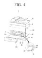
- FIG. 4 is a perspective view illustrating the image forming apparatus of FIG. 3 from which a waste developer receptacle is separated;
- FIG. 5 is a plan view illustrating a light scanning unit disposed in the image forming apparatus of FIG. 2 ;
- FIG. 6 is a sectional view illustrating the light scanning unit of FIG. 5 taken along a line 6-6 in FIG. 5 ;
- FIG. 7 is a sectional view illustrating the light scanning unit of FIG. 5 taken along a line 7-7 in FIG. 5 ;
- FIG. 8 is a sectional view illustrating the light scanning unit of FIG. 5 taken along a line 8-8 in FIG. 5 ;
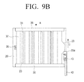
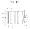
- FIGS. 9A , 9B and 9C are plan views illustrating operation of a window open-closing shutter of a light scanning unit in an image forming apparatus according to an exemplary embodiment of the present disclosure.
- FIG. 10A, 10B , and 10C are partially sectional views illustrating states in that a window member of a light scanning unit is cleaned by a window cleaning member when a window open-closing shutter ofthe light scanning unit operates in an image forming apparatus according to an exemplary embodiment of the present disclosure.
- FIG. 1 is a perspective view schematically illustrating an image forming apparatus according to an exemplary embodiment of the present disclosure.
- FIG. 2 is a sectional view schematically illustrating an image forming apparatus according to an exemplary embodiment of the present disclosure.
- the scanning unit is not illustrated by a cross-section for convenience.
- an image forming apparatus 1 may include a main body 3, a printing media feeding unit 10, a light scanning unit 20, a shutter operating lever 40, an image forming unit 50, an intermediate transfer belt 60, a transfer roller 65, a fusing unit 70, a printing media discharging unit 80, and a scanning unit 95.
- the main body 3 forms an outer appearance of the image forming apparatus 1, is formed in a substantially rectangular shape, and supports and secures the printing media feeding unit 10, the light scanning unit 20, the shutter operating lever 40, the image forming unit 50, the intermediate transfer belt 60, the transfer roller 65, the fusing unit 70, the printing media discharging unit 80, and the scanning unit 95.
- a first opening 6 through which a waste developer receptacle 100 and the image forming unit 50 are mounted into and separated from the main body 3 is formed on one surface ofthe main body 3.
- the surface on which the first opening 6 is formed is referred to a front surface of the main body 3.
- the waste developer receptacle 100 when the waste developer receptacle 100 is mounted into or separated from the inside of the main body 3 through the first opening 6, the waste developer receptacle 100 may be configured to activate the shutter operating lever 40. In other words, the waste developer receptacle 100 may be disposed to play a role of a pressure member to activate the shutter operating lever40.
- FIG. 3 illustrates an open state of a front cover 101 of the image forming apparatus 1 that is formed to open and close the first opening 6.
- the front cover 101 may be disposed by a hinge to rotate a predetermined angle with respect to the main body 3 of the image forming apparatus 1. Alternatively, even though not illustrated, the front cover 101 may be formed to be separated from the main body 3 of the image forming apparatus 1.
- FIG.4 illustrates the image forming apparatus 1 from which the waste developer receptacle 100 is separated through the first opening 6 after the front cover 101 thereof is opened.
- the waste developer receptacle 100 and a plurality of developer supplying receptacle 57 are showed through the first opening 6.
- the waste developer receptacle 100 and the plurality of developer supplying receptacles 57 can be separated from and mounted into through the first opening 6. If the waste developer receptacle 100 is separated, as illustrated in FIG. 4 , the intermediate transfer belt unit 66 and a plurality of image forming units 50 are shown. Accordingly. After the waste developer receptacle 100 is separated, the image forming unit 50 can be separated from or mounted into the main body 3 through the first opening 6.
- the shutter operating lever 40 may be formed to be activated by open-closing operation of the front cover 101.
- the front cover 101 may be formed to perform a function of a pressure member that activates the shutter operating lever 40.
- the shutter operating lever 40 may be formed to be linked to mounting and separating operation of the waste developer receptacle 100 so that only when developer is scattered as described above, the window open-closing shutter 30 is opened and closed.
- the printing media feeding unit 10 is disposed in a bottom of the main body 3 and can store a certain sheets of printing media P.
- the printing media feeding uni 10 may include a printing medium feeding cassette 11 to store printing media P and a pickup roller 13 that can pick up the stored printing media P one by one.
- the pickup roller 13 picks up a printing medium P one by one and feeds the printing medium P to the transfer roller 65 according to a printing command ofthe control portion 90..
- the image forming unit 50 forms images corresponding to printing data and is configured of a photosensitive medium unit 51 and a developing roller unit 52.
- the photosensitive medium unit 51 and the developing roller unit 52 may be formed separately from each other.
- the photosensitive medium unit 51 may include a photosensitive medium 53 on a surface of which an electrostatic latent image is formed, a charging roller (not illustrated) for charging the surface of the photosensitive medium 53, and a cleaning member (not illustrated) for removing waste developer remaining on the surface of the photosensitive medium 53.
- the developing roller unit 52 may include a developing roller 54 that supplies developer to the photosensitive medium 53 to develop an electrostatic latent image into a developer image, a developer supplying roller (not illustrated) that supplies developer to the developing roller 54, a blade (not illustrated) that regulates developer attached on the surface of the photosensitive medium 53 to have a predetermined thickness and charges the developer, and a developer storing portion (not illustrated) that stores a predetermined amount of developer.
- the image forming apparatus 1 may include at least one image forming unit 50. In the present exemplary embodiment, for forming a color image four image forming units 50 are disposed in a line. Also, after the front cover 101 is opened and the waste developer receptacle 100 is separated, the image forming unit 50 can be accessed. In other words, after the front cover 101 is opened and then the waste developer receptacle 100 is separated from the main body 3, the developing roller unit 52 and the photosensitive medium unit 51 can be mounted into or separated from the main body 3 through the first opening 6.
- the waste developer receptacle 100 is formed to receive waste developer removed from the photosensitive medium unit 51 after an image is formed. Accordingly, although not illustrated in FIGS. 1 and 2 , a waste developer discharging member (not illustrated) that discharges waste developer removed from the photosensitive medium unit 51 into the waste developer receptacle 100 is disposed between the photosensitive medium unit 51 and the waste developer receptacle 100.
- the light scanning unit 20 scans light corresponding to printing data to the photosensitive medium 53 ofthe image forming unit 50 according to a printing command ofthe control portion 90 so as to form an electrostatic latent image on the surface of the photosensitive medium 53.
- the light scanning unit 20 includes a housing 21, a light source (not illustrated) that is disposed inside the housing and emits light, a polygon mirror (not illustrated) that rotates and scans the light emitted from the light source, an f ⁇ lens (not illustrated) to focus the light reflected from the polygon mirror on the surface of the photosensitive medium 53, and a window member 23 which is disposed on a top surface of the housing 21 and the light coming from the f ⁇ lens passes through.
- the structure of the light scanning unit 20 as described above is the same as that of a conventional light scanning unit. Therefore, a detailed description thereof will be omitted. Also, in FIGS. 7 and 8 , the light source, polygon mirror, f ⁇ lens, and like disposed inside the housing 21 of the light scanning unit 20 are omitted and only window member 23 required for explanation of the present disclosure is illustrated.
- At least one window member 23 is disposed on the top surface of the housing 21 of the light scanning unit 20. Accordingly, the light emitted from the light source passes through the f ⁇ lens and the window member 23 and then are scanned to the photosensitive medium 53.
- the light scanning unit 20 since four image forming units 50 are used, the light scanning unit 20 includes four light sources. Accordingly, four window members 23 also are disposed to correspond to the image forming units 50.
- a window open-closing shutter 30 is disposed on a top surface ofthe housing 21 of the light scanning unit 20.
- the window open-closing shutter 30 is disposed to slidably move with respect to the top surface of the housing 21.
- the window open-closing shutter 30 is spaced apart at a predetermined distance from the top surface ofthe housing 21.
- Opposite side ends of the window open-closing shutter 30 are supported by shutter guiding members 36 projecting from the top surface of the housing 21. Accordingly, the window open-closing shutter 30 can reciprocate linearly along the shutter guiding members 36 in directions of arrow A and B.
- An inclined portion 33 is formed on one end of the window open-closing shutter 30.
- the inclined portion 33 is formed to project in a trapezoidal shape from a middle portion of the one end of the window open-closing shutter 30.
- An inclined surface 33a of the inclined portion 33 is in contact with a first end of the shutter operating lever 40 and converts the linear reciprocation of the shutter operating lever 40 into the linear reciprocation of the window open-closing shutter 30. Accordingly, when the shutter operating lever 40 reciprocates linearly, the window open-closing shutter 30 is reciprocated linearly in a direction of 90 degrees with respect to the moving direction of the shutter operating lever 40.
- a restoring member 39 is disposed on the other end of the window open-closing shutter 30, that is, on the end opposite where the inclined portion 33 is disposed.
- the restoring member 39 allows the window open-closing shutter 30 to always return to an original position thereof, that is, where a blocking portion 32 of the window open-closing shutter 30 covers the window member 23.
- a compression coil spring may be used as the restoring member 39.
- the compression coil spring is only one example: therefore, various members can be used as the restoring member 39 as long as they can apply force to the window open-closing shutter 30 so as to restore the window open-closing shutter 30 to the original position thereof.
- the window open-closing shutter 30 is provided with four light slots 31 and four blocking portions 32.
- the light slot 31 is formed to correspond to the window member 23 disposed on the housing 21 of the light scanning unit 20. Accordingly, when the light slot 31 is positioned in a location where the light slot 31 is aligned with the window member 23, a light passing path is opened so that light emitted from the light source is scanned to the photosensitive medium 53. If the light slot 31 is not aligned with the window member 23, the blocking portion 32 of the window open-closing shutter 30 covers the window member 23 to block the light passing path. As a result, the light emitting from the light source is not scanned to the photosensitive medium 53.
- a position of the window open-closing shutter 30 where the light slot 31 is aligned with the window member 23 is referred to an open position
- a position of the window open-closing shutter 30 where the light slot 31 is not aligned with the window member 23 and the blocking portion 32 covers the window member 23 is referred to a blocking position. Accordingly, the window open-closing shutter 30 can reciprocate linearly between the open position and the blocking position.
- a window cleaning member 110 may be disposed on a bottom surface of the window open-closing shutter 30 to clean the top surface of the window member 23.
- the window cleaning member 110 is disposed to rub against the top surface of the window member 23 when the window open-closing shutter 30 reciprocates linearly.
- the window cleaning member 110 is disposed at a side of the light slot 31, and has a length longer than that of the light slot 31.
- the height of the window cleaning member 110 is determined so that when the window open-closing shutter 30 reciprocates linearly, the window cleaning member 110 is in contact with the top surface of the window member 23 and removes developer or/and paper dust attached on the window member 23. Accordingly, the window cleaning member 110 is formed to have the number corresponding to the number of the window member 23. In the present exemplary embodiment, since there are four window members 23, four window cleaning members 110 are provided.
- the window cleaning member 110 may be formed of a material such as rubber that can remove developer and paper dust attached on the window member 23.
- the shutter operating lever 40 is formed in a substantially bar shape and is disposed near where the light scanning unit 20 is disposed in the main body 3. In other words, a first end 41 of the shutter operating lever 40 is in contact with the inclined portion 33 of the window open-closing shutter 30 of the light scanning unit 20 mounted in the main body 3 and a second end 42 opposite to the first end 41 is disposed to project in the first opening 6 as illustrated in FIG. 4 .
- the shutter operating lever 40 may be activated by a pressure member that is detachably mounted in the main body 3.
- FIGS. 3 and 4 illustrate the image forming apparatus 1 using the waste developer receptacle 100 as the pressure member.
- the photosensitive medium unit 51 or the developing roller unit 52 configuring the image forming unit 50 may be used as the pressure member.
- the shutter operating lever 40 is formed to be activated.
- the photosensitive medium unit 51 or the developing roller unit 53 is separated, although developer is scattered, the light scanning unit 20 can be prevented from being contaminated by the scattered developer.
- the shutter operating lever 40 is supported to slidably move by a lever guiding member 46.
- the lever guiding member 46 is disposed in the main body 3 of the image forming apparatus 1 and guides the shutter operating lever 40 to reciprocate linearly, that is, to perform a sliding movement in a direction perpendicular to the moving direction of the window open-closing shutter 30.
- the lever guiding member 46 supports the shutter operating lever 40 to move in a main scanning direction, that is, in a lengthwise direction of the light slot 31 of the window open-closing shutter 30 (in a direction parallel to arrow D).
- the window open-closing shutter 30 is moved in a sub scanning direction (in a direction parallel to arrow A) perpendicular to the main scanning direction by the inclined portion 33.
- An elastic member 43 is disposed between the lever guiding member 46 and the shutter operating lever 40.
- the elastic member 43 elastically supports the shutter operating lever 40 in the direction away from the inclined portion 33 of the window open-closing shutter 30 (in a direction of arrow C).
- One end of the elastic member 43 is fixed to a protrusion 44 of the shutter operating lever 40 and the other end of the elastic member 43 is fixed to a protrusion 47 of the lever guiding member 46 so that the elastic member 43 can apply force to the shutter operating lever 40 in the direction of arrow C. Accordingly, if no force is applied to the shutter operating lever 40 from the outside, the shutter operating lever 40 does not apply force to the inclined portion 33 of the window open-closing shutter 30.
- a plurality of supporting protrusions 48 may be formed in the lever guiding member 46 to support the shutter operating lever 40 so that the shutter operating lever 40 can slidably move in a stable state.
- the window open-closing shutter 30 of the light scanning unit 20 is opened.
- the window open-closing shutter 30 of the light scanning unit 20 is closed.
- the intermediate transfer belt unit 60 onto which a developer image formed on the photosensitive medium 53 of each of the four image forming units 50 is overlappingly transferred forms a color image.
- the intermediate transfer belt unit 60 includes an intermediate transfer belt 61, and a driving roller 62 and a driven roller 63 that drive the intermediate transfer belt 61 to move in an endless track motion.
- the intermediate transfer belt unit 60 may be formed in one unit.
- a second opening 7 through which the intermediate transfer belt unit 60 can be mounted into and separated from the main body 3 may be formed on a side surface of the main body 3.
- the main body 3 may be provided with a side cover 103 to open and close the second opening 7. Accordingly, when the side cover 103 is opened, the intermediate transfer belt unit 60 can be mounted into and separated from the main body 3 through the second opening 7.
- At least one developer supplying receptacle 57 may be disposed above the intermediate transfer belt unit 60.
- the developer supplying receptacle 57 stores a predetermined developer, and supplies developer to the developing roller unit 52 of the image forming unit 50.
- the developing roller unit 52 and the developer supplying receptacle 57 are connected with each other by a connecting member (not illustrated). Accordingly, the developer stored in the developer supplying receptacle 57 is supplied to the developing roller unit 52 through the connecting member.
- the developer supplying receptacle 57 may be provided with the same number as that ofthe image forming unit 50. In the present exemplary embodiment, since four image forming units 50 are disposed, the four developer supplying receptacles 57 also are disposed.
- the transfer roller 65 is disposed to rotate in contact with the intermediate transfer belt 61, and allows the color developer image formed on the intermediate transfer belt 61 to be transferred onto a printing medium P entering between the transfer roller 65 and the intermediate transfer belt 61.
- the fusing unit 70 applies heat and pressure to the printing medium P that has passed the transfer roller 65 so as to fuse the transferred developer image onto the printing medium P.
- the fusing unit 70 includes a pressing roller 71 and a heating roller 72 that rotate to face each other.
- the printing media discharging unit 80 discharges the printing medium P on which the developer image is fused during passage of the fusing unit 70 onto a printing media discharging tray 5 outside the main body 3.
- the printing media discharging unit 80 may have two printing media discharging rollers.
- the scanning unit 95 is disposed above the printing media discharging unit 80 and the printing media discharging tray 5, and can read a document to get an image data.
- a scanning sensor (not illustrated) to read a document is disposed in the scanning unit 95.
- the inclined portion 33 of the window open-closing shutter 30 is positioned near the first end of the shutter operating lever 40 disposed in the main body 3.
- the blocking portion 32 of the window open-closing shutter 30 covers the window member 23 of the window open-closing shutter 30.
- the window open-closing shutter 30 is positioned at the blocking position.
- the second end 42 of the shutter operating lever 40 projects in the first opening 6 of the front surface of the main body 3 by the elastic member 43.
- a worker mounts the waste developer receptacle 100 into the first opening 6. If the waste developer receptacle 100 is mounted into the first opening 6, the waste developer receptacle 100 presses the projecting second end 42 of the shutter operating lever 40. If the waste developer receptacle 100 presses the second end 42 of the shutter operating lever 40, the shutter operating lever 40 is moved toward the inclined portion 33 of the window open-closing shutter 30. In other words, the shutter operating lever 40 moves in a direction of arrow D in FIG. 9b .
- the shutter operating lever 40 moves in the direction of arrow D, the first end 41 of the shutter operating lever 40 pushes the inclined surface 33a of the inclined portion 33 of the window open-closing shutter 30 so that the window open-closing shutter 30 is moved in the direction of arrow A.
- the shutter operating lever 40 is positioned at a bottom end 33b of the inclined portion 33 of the window open-closing shutter 30.
- the window open-closing shutter 30 is positioned at the open position, the light slot 31 of the window open-closing shutter 30 is positioned above the window member 23 so that light emitted from the window member 23 can pass through the light slot 31 and then become incident on the photosensitive medium 53.
- the image forming apparatus 1 can normally perform printing.
- the waste developer receptacle 100 is filled with waste developer. Then, a user needs to separate the waste developer receptacle 100 from the image forming apparatus 1 and then empty waste developer from the waste developer receptacle 100.
- the user opens the front cover 101 of the main body 3. Then, as illustrated in FIG. 3 , the waste developer receptacle 100 is exposed through the first opening 6.
- the force applied to the shutter operating lever 40 by the waste developer receptacle 100 is removed. Then, the shutter operating lever 40 is moved in a direction of arrow C in FIG. 9c by the elastic member 43 and then the second end 42 of the shutter operating lever 40 projects in the first opening 6.
- the shutter operating lever 40 moves in the direction arrow C in FIG. 9c , the window open-closing shutter 30 is moved in the direction of arrow B in FIG. 9c by the restoring member 39.
- the window open-closing shutter 30 moves in the direction of arrow B, the light slot 31 gets out of above the window member 23 and the blocking portion 32 of the window open-closing shutter 30 is positioned above the window member 23 so that the window open-closing shutter 30 is restored to the state of FIG. 9a , that is, the blocking position. Accordingly, light emitting from the window member 23 is blocked by the blocking portion 32 of the window open-closing shutter 30.
- the window open-closing shutter 30 blocks the window member 23 of the light scanning unit 20 so as to prevent the window member 23 from being contaminated by scattered developer.
- the user After the user removes waste developer from the waste developer receptacle 100, the user remounts the waste developer receptacle 100 into the first opening 6. After the waste developer receptacle 100 is remounted into the first opening 6, the shutter operating lever 40 is moved in the direction of arrow D by the waste developer receptacle 100, and then, the window open-closing shutter 30 is moved in the direction of arrow A by the shutter operating lever 40 so that the light slot 31 is positioned above the window member 23. Accordingly, when the light scanning unit 20 emits light, the light can become incident on the photosensitive medium 53 through the light slot 31.
- window open-closing shutter 30 When the window open-closing shutter 30 is moved by mounting and separating of the waste developer receptacle 100, if the window cleaning member 110 is disposed on the bottom surface of the window open-closing shutter 30, the window cleaning member 110 is moved to clean developer attached on the window member 23.
- a process for the window cleaning member 110 to clean the window member 23 will be explained with reference to FIGS. 10a, 10b , and 10c , hereinafter.
- the image forming apparatus 1 can normally perform printing.
- the shutter operating lever 40 is maximally moved by the waste developer receptacle 100, as illustrated in FIG. 9c , so as to be positioned at the bottom end 33b of the inclined portion 33 of the window open-closing shutter 30.
- the light slot 31 of the window open-closing shutter 30 is positioned above the window member 23 of the light scanning unit 20 so that the light emitting from the window member 23 of the light scanning unit 20 passes through the light slot 31 of the window open-closing shutter 30 and becomes incident on the photosensitive medium 53.
- the window cleaning member 110 is positioned at the left side of the window member 23 as illustrated in FIG. 10a . Accordingly, the light emitting from the window member 23 of the light scanning unit 20 does not interfere with the window cleaning member 110.
- the user separates the waste developer receptacle 100 from the first opening 6 of the image forming apparatus 1.
- the second end 42 of the shutter operating lever 40 projects in the first opening 6 by the elastic member 43 and the window open-closing shutter 30 is moved in the direction of arrow B (see FIG. 9c ) by the restoring member 39.
- the window cleaning member 110 disposed on the bottom surface of the window open-closing shutter 30 passes the top surface of the window member 23 while being in contact with the top surface of the window member 23.
- the shutter operating lever 40 When the second end 42 of the shutter operating lever 40 is maximally projected in the first opening 6 by the elastic member 43, the shutter operating lever 40 does not press the inclined portion 33 of the window open-closing shutter 30. As illustrated in FIG. 9a , when the shutter operating lever 40 does not press the inclined portion 33 of the window open-closing shutter 30, the window cleaning member 110 is positioned at the right side of the window member 23 as illustrated in FIG. 10c . Accordingly, the light emitting from the window member 23 of the light scanning unit 20 does not interfere with the window cleaning member 110.
- the waste developer receptacle 100 presses the second end 42 of the shutter operating lever 40. Then, the first end 41 of the shutter operating lever 40 presses the inclined surface 33a of the inclined portion 33 of the window open-closing shutter 30 so that the window open-closing shutter 30 is moved in the direction of arrow A. At this time, the window cleaning member 110 disposed on the bottom surface of the window open-closing shutter 30, as illustrated in FIG. 10b , passes the top surface of the window member 23 while being in contact with the top surface ofthe window member 23.
- the shutter operating lever 40 When the shutter operating lever 40 is maximally moved and is positioned at the bottom end 33b of the inclined portion 33 of the window open-closing shutter 30, the light slot 31 of the window open-closing shutter 30, as illustrated in FIG. 10b , is positioned above the window member 23. Then the window cleaning member 110 is moved to the left side of the window member 23 to return to the original position thereof.
- the window cleaning member 110 passes twice the top surface of the window member 23 of the light scanning unit 20 by separating and mounting operation of the waste developer receptacle 100. Accordingly, developer or/and paper dust attached on the top surface of the window member 23 of the light scanning unit 20 is removed by the window cleaning member 110 that moves rubbing against the window member 23.
- a window open-closing shutter of a light scanning unit blocks a window member, the light scanning unit can be prevented from being contaminated by developer scattered when the waste developer receptacle is replaced.
- a waste developer receptacle is first separated before the photosensitive medium unit and the developing roller unit are changed.
- a window open-closing shutter blocks a window member of the light scanning unit so as to prevent the light scanning unit from being contaminated by the scattered developer.
- the waste developer receptacle, the photosensitive medium unit, and the developing roller unit press the shutter operating lever.
- the present disclosure is not limited by the above disclosure.
- Various parts can be disposed to activate the shutter operating lever as long as they can be detachably disposed in the main body of the image forming apparatus.
Landscapes
- Physics & Mathematics (AREA)
- General Physics & Mathematics (AREA)
- Life Sciences & Earth Sciences (AREA)
- Engineering & Computer Science (AREA)
- Environmental & Geological Engineering (AREA)
- Sustainable Development (AREA)
- Electrophotography Configuration And Component (AREA)
- Facsimile Scanning Arrangements (AREA)
Abstract
Description
- The present disclosure relates to an image forming apparatus. More particularly, the present disclosure relates to an image forming apparatus having a window open-closing shutter and a shutter operating lever that can selectively open and close a window member of a light scanning unit that scans light to form an electrostatic latent image.
- Generally, an electro-photographic image forming apparatus, such as a copy machine, a light printer, a facsimile machine, a multifunctional product or the like, includes a light scanning unit scanning light corresponding to printing data for forming an electrostatic latent image on a photosensitive medium.
- The light scanning unit uses an optical deflector such as a rotating polygon mirror so as to periodically deflect light emitted from a light source, and uses an fθ lens to focus the light on a surface of the photosensitive medium having photosensitivity such as a photosensitive drum so as to form an electrostatic latent image thereon.
- The light scanning unit may include a window open-closing shutter that can selectively open and close a window member from which light is emitted so as to prevent the window member from being contaminated by developer and paper dust generated during printing.
- However, in order to perform open-closing operation, the window open-closing shutter of the conventional light scanning unit needs a separate driving apparatus and a power transmitting apparatus such as gears or cams to transmit power generated by the driving apparatus to the window open-closing shutter. Accordingly, the light scanning unit having the window open-closing shutter has a complex structure and a high material cost, and due to the difficulty of assembly and repair, management fees of the image forming apparatus is raised.
- For solving the problems, the light scanning unit may be formed to have no window open-closing shutter. However, if there is no window open-closing shutter, there is a problem that when an image forming unit or a waste developer receptacle is separated from an image forming apparatus, developer is scattered so as to contaminate the window member of the light scanning unit, and then, give an adverse effect on image quality.
- The present disclosure has been developed in order to overcome the above drawbacks and other problems associated with the conventional arrangement. An aspect of the present disclosure relates an image forming apparatus having a light scanning unit that can open and close a window open-closing shutter without using a separate driving apparatus and a power transmitting apparatus.
- The above aspect and/or other feature of the present disclosure can substantially be achieved by providing an image forming apparatus, which may include a main body of the image forming apparatus; at least one image forming unit disposed in the main body; a light scanning unit that is disposed in the main body and scans light to form an electrostatic latent image on a photosensitive medium of the at least one image forming unit; a window open-closing shutter that is disposed to slidably move on a surface of the light scanning unit from which light emits, and moves between an open position where a light moving path is opened and a blocking position where the light moving path is blocked; a shutter operating lever that is disposed in the main body, and activates the window open-closing shutter to be positioned at either of the open position and the blocking position; and a pressure member that is disposed in the main body and presses the shutter operating lever.
- The window open-closing shutter may include an inclined portion to come in contact with the shutter operating lever. When an end of the shutter operating lever presses the inclined portion, the window open-closing shutter may be positioned at the open position, and when the end of the shutter operating lever does not press the inclined portion, the window open-closing shutter may be positioned at the blocking position.
- The window open-closing shutter and the shutter operating lever may move in directions perpendicular to each other on the same plan.
- The window open-closing shutter may move in a sub-scanning direction and the shutter operating lever moves in a main scanning direction.
- The image forming apparatus may include a restoring member that restores the window open-closing shutter to an original position thereof.
- The restoring member may include a compression coil spring.
- The pressure member may include a waste developer receptacle disposed at a side of the at least one image forming unit in the main body.
- The pressure member may include a door that is disposed in the main body, and opens and closes a portion ofthe main body to access an interior ofthe main body.
- The image forming apparatus may include a lever guiding member that is disposed in the main body and guides the shutter operating lever to slidably move.
- The image forming apparatus may include an elastic member that is disposed in the lever guiding member and elastically supports the shutter operating lever.
- The light scanning unit may include a window member through which the light passes, and a window cleaning member that is disposed on the window open-closing shutter and cleans the window member by sliding movement of the window open-closing shutter.
- The window cleaning member may be formed of rubber.
- Other objects, advantages and salient features of the present disclosure will become apparent from the following detailed description, which, taken in conjunction with the annexed drawings, discloses preferred embodiments.
- These and/or other aspects and advantages of the present disclosure will become apparent and more readily appreciated from the following description of the embodiments, taken in conjunction with the accompanying drawings of which:
-
FIG. 1 is a perspective view schematically illustrating an image forming apparatus according to an exemplary embodiment of the present disclosure; -
FIG. 2 is a sectional view schematically illustrating an image forming apparatus according to an exemplary embodiment of the present disclosure; -
FIG. 3 is a perspective view illustrating an image forming apparatus according to an exemplary embodiment of the present disclosure a front cover of which is opened; -
FIG. 4 is a perspective view illustrating the image forming apparatus ofFIG. 3 from which a waste developer receptacle is separated; -
FIG. 5 is a plan view illustrating a light scanning unit disposed in the image forming apparatus ofFIG. 2 ; -
FIG. 6 is a sectional view illustrating the light scanning unit ofFIG. 5 taken along a line 6-6 inFIG. 5 ; -
FIG. 7 is a sectional view illustrating the light scanning unit ofFIG. 5 taken along a line 7-7 inFIG. 5 ; -
FIG. 8 is a sectional view illustrating the light scanning unit ofFIG. 5 taken along a line 8-8 inFIG. 5 ; -
FIGS. 9A ,9B and9C are plan views illustrating operation of a window open-closing shutter of a light scanning unit in an image forming apparatus according to an exemplary embodiment of the present disclosure; and -
FIG. 10A, 10B , and10C are partially sectional views illustrating states in that a window member of a light scanning unit is cleaned by a window cleaning member when a window open-closing shutter ofthe light scanning unit operates in an image forming apparatus according to an exemplary embodiment of the present disclosure. - Throughout the drawings, like reference numerals will be understood to refer to like parts, components and structures.
- Hereinafter, certain exemplary embodiments of the present disclosure will be described in detail with reference to the accompanying drawings.
- The matters defined herein, such as a detailed construction and elements thereof, are provided to assist in a comprehensive understanding of this description. Thus, it is apparent that exemplary embodiments may be carried out without those defined matters. Also, well-known functions or constructions are omitted to provide a clear and concise description of exemplary embodiments. Further, dimensions of various elements in the accompanying drawings may be arbitrarily increased or decreased for assisting in a comprehensive understanding.
-
FIG. 1 is a perspective view schematically illustrating an image forming apparatus according to an exemplary embodiment of the present disclosure.FIG. 2 is a sectional view schematically illustrating an image forming apparatus according to an exemplary embodiment of the present disclosure. However, since the present disclosure does not need explanation with respect to an internal structure of a scanning unit, inFIG. 2 , the scanning unit is not illustrated by a cross-section for convenience. - Referring to
FIGS. 1 and2 , animage forming apparatus 1 according to an exemplary embodiment of the present disclosure may include amain body 3, a printingmedia feeding unit 10, alight scanning unit 20, ashutter operating lever 40, animage forming unit 50, anintermediate transfer belt 60, atransfer roller 65, afusing unit 70, a printingmedia discharging unit 80, and ascanning unit 95. - The
main body 3 forms an outer appearance of theimage forming apparatus 1, is formed in a substantially rectangular shape, and supports and secures the printingmedia feeding unit 10, thelight scanning unit 20, theshutter operating lever 40, theimage forming unit 50, theintermediate transfer belt 60, thetransfer roller 65, thefusing unit 70, the printingmedia discharging unit 80, and thescanning unit 95. - A
first opening 6 through which awaste developer receptacle 100 and theimage forming unit 50 are mounted into and separated from themain body 3 is formed on one surface ofthemain body 3. Hereinafter, the surface on which thefirst opening 6 is formed is referred to a front surface of themain body 3. - Further, when the
waste developer receptacle 100 is mounted into or separated from the inside of themain body 3 through thefirst opening 6, thewaste developer receptacle 100 may be configured to activate theshutter operating lever 40. In other words, thewaste developer receptacle 100 may be disposed to play a role of a pressure member to activate the shutter operating lever40. -
FIG. 3 illustrates an open state of afront cover 101 of theimage forming apparatus 1 that is formed to open and close thefirst opening 6. Thefront cover 101 may be disposed by a hinge to rotate a predetermined angle with respect to themain body 3 of theimage forming apparatus 1. Alternatively, even though not illustrated, thefront cover 101 may be formed to be separated from themain body 3 of theimage forming apparatus 1.FIG.4 illustrates theimage forming apparatus 1 from which thewaste developer receptacle 100 is separated through thefirst opening 6 after thefront cover 101 thereof is opened. - When the
front cover 101 is opened, as illustrated inFIG. 3 , thewaste developer receptacle 100 and a plurality ofdeveloper supplying receptacle 57 are showed through thefirst opening 6. Thewaste developer receptacle 100 and the plurality ofdeveloper supplying receptacles 57 can be separated from and mounted into through thefirst opening 6. If thewaste developer receptacle 100 is separated, as illustrated inFIG. 4 , the intermediate transfer belt unit 66 and a plurality ofimage forming units 50 are shown. Accordingly. After thewaste developer receptacle 100 is separated, theimage forming unit 50 can be separated from or mounted into themain body 3 through thefirst opening 6. - Alternatively, the
shutter operating lever 40 may be formed to be activated by open-closing operation of thefront cover 101. In other words, thefront cover 101 may be formed to perform a function of a pressure member that activates theshutter operating lever 40. However, if theshutter operating lever 40 is formed to be activated by thefront cover 101, a window open-closingshutter 30 is frequently opened and closed. Therefore, theshutter operating lever 40 may be formed to be linked to mounting and separating operation of thewaste developer receptacle 100 so that only when developer is scattered as described above, the window open-closingshutter 30 is opened and closed. - The printing
media feeding unit 10 is disposed in a bottom of themain body 3 and can store a certain sheets of printing media P. The printingmedia feeding uni 10 may include a printingmedium feeding cassette 11 to store printing media P and apickup roller 13 that can pick up the stored printing media P one by one. Thepickup roller 13 picks up a printing medium P one by one and feeds the printing medium P to thetransfer roller 65 according to a printing command ofthecontrol portion 90.. - The
image forming unit 50 forms images corresponding to printing data and is configured of a photosensitivemedium unit 51 and a developingroller unit 52. The photosensitivemedium unit 51 and the developingroller unit 52 may be formed separately from each other. The photosensitivemedium unit 51 may include a photosensitive medium 53 on a surface of which an electrostatic latent image is formed, a charging roller (not illustrated) for charging the surface of thephotosensitive medium 53, and a cleaning member (not illustrated) for removing waste developer remaining on the surface of thephotosensitive medium 53. The developingroller unit 52 may include a developingroller 54 that supplies developer to the photosensitive medium 53 to develop an electrostatic latent image into a developer image, a developer supplying roller (not illustrated) that supplies developer to the developingroller 54, a blade (not illustrated) that regulates developer attached on the surface of the photosensitive medium 53 to have a predetermined thickness and charges the developer, and a developer storing portion (not illustrated) that stores a predetermined amount of developer. Theimage forming apparatus 1 may include at least oneimage forming unit 50. In the present exemplary embodiment, for forming a color image fourimage forming units 50 are disposed in a line. Also, after thefront cover 101 is opened and thewaste developer receptacle 100 is separated, theimage forming unit 50 can be accessed. In other words, after thefront cover 101 is opened and then thewaste developer receptacle 100 is separated from themain body 3, the developingroller unit 52 and the photosensitivemedium unit 51 can be mounted into or separated from themain body 3 through thefirst opening 6. - The
waste developer receptacle 100 is formed to receive waste developer removed from the photosensitivemedium unit 51 after an image is formed. Accordingly, although not illustrated inFIGS. 1 and2 , a waste developer discharging member (not illustrated) that discharges waste developer removed from the photosensitivemedium unit 51 into thewaste developer receptacle 100 is disposed between the photosensitivemedium unit 51 and thewaste developer receptacle 100. - The
light scanning unit 20 scans light corresponding to printing data to thephotosensitive medium 53 oftheimage forming unit 50 according to a printing command ofthecontrol portion 90 so as to form an electrostatic latent image on the surface of thephotosensitive medium 53. Thelight scanning unit 20 includes ahousing 21, a light source (not illustrated) that is disposed inside the housing and emits light, a polygon mirror (not illustrated) that rotates and scans the light emitted from the light source, an fθ lens (not illustrated) to focus the light reflected from the polygon mirror on the surface of thephotosensitive medium 53, and awindow member 23 which is disposed on a top surface of thehousing 21 and the light coming from the fθ lens passes through. The structure of thelight scanning unit 20 as described above is the same as that of a conventional light scanning unit. Therefore, a detailed description thereof will be omitted. Also, inFIGS. 7 and8 , the light source, polygon mirror, fθ lens, and like disposed inside thehousing 21 of thelight scanning unit 20 are omitted and onlywindow member 23 required for explanation of the present disclosure is illustrated. - At least one
window member 23 is disposed on the top surface of thehousing 21 of thelight scanning unit 20. Accordingly, the light emitted from the light source passes through the fθ lens and thewindow member 23 and then are scanned to thephotosensitive medium 53. In this exemplary embodiment, since fourimage forming units 50 are used, thelight scanning unit 20 includes four light sources. Accordingly, fourwindow members 23 also are disposed to correspond to theimage forming units 50. - A window open-closing
shutter 30 is disposed on a top surface ofthehousing 21 of thelight scanning unit 20. The window open-closingshutter 30 is disposed to slidably move with respect to the top surface of thehousing 21. In other words, the window open-closingshutter 30 is spaced apart at a predetermined distance from the top surface ofthehousing 21. Opposite side ends of the window open-closingshutter 30 are supported byshutter guiding members 36 projecting from the top surface of thehousing 21. Accordingly, the window open-closingshutter 30 can reciprocate linearly along theshutter guiding members 36 in directions of arrow A and B. - An
inclined portion 33 is formed on one end of the window open-closingshutter 30. Theinclined portion 33 is formed to project in a trapezoidal shape from a middle portion of the one end of the window open-closingshutter 30. Aninclined surface 33a of theinclined portion 33 is in contact with a first end of theshutter operating lever 40 and converts the linear reciprocation of theshutter operating lever 40 into the linear reciprocation of the window open-closingshutter 30. Accordingly, when theshutter operating lever 40 reciprocates linearly, the window open-closingshutter 30 is reciprocated linearly in a direction of 90 degrees with respect to the moving direction of theshutter operating lever 40. - A restoring
member 39 is disposed on the other end of the window open-closingshutter 30, that is, on the end opposite where theinclined portion 33 is disposed. When theshutter operating lever 40 does not apply force to theinclined portion 33, the restoringmember 39 allows the window open-closingshutter 30 to always return to an original position thereof, that is, where a blockingportion 32 of the window open-closingshutter 30 covers thewindow member 23. A compression coil spring may be used as the restoringmember 39. However, the compression coil spring is only one example: therefore, various members can be used as the restoringmember 39 as long as they can apply force to the window open-closingshutter 30 so as to restore the window open-closingshutter 30 to the original position thereof. - Also, the window open-closing
shutter 30 is provided with fourlight slots 31 and four blockingportions 32. Thelight slot 31 is formed to correspond to thewindow member 23 disposed on thehousing 21 of thelight scanning unit 20. Accordingly, when thelight slot 31 is positioned in a location where thelight slot 31 is aligned with thewindow member 23, a light passing path is opened so that light emitted from the light source is scanned to thephotosensitive medium 53. If thelight slot 31 is not aligned with thewindow member 23, the blockingportion 32 of the window open-closingshutter 30 covers thewindow member 23 to block the light passing path. As a result, the light emitting from the light source is not scanned to thephotosensitive medium 53. In a below explanation, a position of the window open-closingshutter 30 where thelight slot 31 is aligned with thewindow member 23 is referred to an open position, and a position of the window open-closingshutter 30 where thelight slot 31 is not aligned with thewindow member 23 and the blockingportion 32 covers thewindow member 23 is referred to a blocking position. Accordingly, the window open-closingshutter 30 can reciprocate linearly between the open position and the blocking position. - Further, a
window cleaning member 110 may be disposed on a bottom surface of the window open-closingshutter 30 to clean the top surface of thewindow member 23. Thewindow cleaning member 110 is disposed to rub against the top surface of thewindow member 23 when the window open-closingshutter 30 reciprocates linearly. Thewindow cleaning member 110 is disposed at a side of thelight slot 31, and has a length longer than that of thelight slot 31. Also, the height of thewindow cleaning member 110 is determined so that when the window open-closingshutter 30 reciprocates linearly, thewindow cleaning member 110 is in contact with the top surface of thewindow member 23 and removes developer or/and paper dust attached on thewindow member 23. Accordingly, thewindow cleaning member 110 is formed to have the number corresponding to the number of thewindow member 23. In the present exemplary embodiment, since there are fourwindow members 23, fourwindow cleaning members 110 are provided. Thewindow cleaning member 110 may be formed of a material such as rubber that can remove developer and paper dust attached on thewindow member 23. - The
shutter operating lever 40 is formed in a substantially bar shape and is disposed near where thelight scanning unit 20 is disposed in themain body 3. In other words, afirst end 41 of theshutter operating lever 40 is in contact with theinclined portion 33 of the window open-closingshutter 30 of thelight scanning unit 20 mounted in themain body 3 and asecond end 42 opposite to thefirst end 41 is disposed to project in thefirst opening 6 as illustrated inFIG. 4 . Theshutter operating lever 40 may be activated by a pressure member that is detachably mounted in themain body 3.FIGS. 3 and4 illustrate theimage forming apparatus 1 using thewaste developer receptacle 100 as the pressure member. Although not illustrated, the photosensitivemedium unit 51 or the developingroller unit 52 configuring theimage forming unit 50 may be used as the pressure member. In this case, when any one of four photosensitive medium units 51and four developingroller units 53 is separated from themain body 3, theshutter operating lever 40 is formed to be activated. As a result, when the photosensitivemedium unit 51 or the developingroller unit 53 is separated, although developer is scattered, thelight scanning unit 20 can be prevented from being contaminated by the scattered developer. - The
shutter operating lever 40 is supported to slidably move by alever guiding member 46. Thelever guiding member 46 is disposed in themain body 3 of theimage forming apparatus 1 and guides theshutter operating lever 40 to reciprocate linearly, that is, to perform a sliding movement in a direction perpendicular to the moving direction of the window open-closingshutter 30. Thelever guiding member 46 supports theshutter operating lever 40 to move in a main scanning direction, that is, in a lengthwise direction of thelight slot 31 of the window open-closing shutter 30 (in a direction parallel to arrow D). When theshutter operating lever 40 moves in the main scanning direction, the window open-closingshutter 30 is moved in a sub scanning direction (in a direction parallel to arrow A) perpendicular to the main scanning direction by theinclined portion 33. - An
elastic member 43 is disposed between thelever guiding member 46 and theshutter operating lever 40. Theelastic member 43 elastically supports theshutter operating lever 40 in the direction away from theinclined portion 33 of the window open-closing shutter 30 (in a direction of arrow C). One end of theelastic member 43 is fixed to aprotrusion 44 of theshutter operating lever 40 and the other end of theelastic member 43 is fixed to aprotrusion 47 of thelever guiding member 46 so that theelastic member 43 can apply force to theshutter operating lever 40 in the direction of arrow C. Accordingly, if no force is applied to theshutter operating lever 40 from the outside, theshutter operating lever 40 does not apply force to theinclined portion 33 of the window open-closingshutter 30. Further, a plurality of supportingprotrusions 48 may be formed in thelever guiding member 46 to support theshutter operating lever 40 so that theshutter operating lever 40 can slidably move in a stable state. - As described above, since the
shutter operating lever 40 is supported to linearly move by thelever guiding member 46 disposed in themain body 3 of theimage forming apparatus 1, when thesecond end 42 of theshutter operating lever 40 receives force, the window open-closingshutter 30 of thelight scanning unit 20 is opened. When the force is removed from thesecond end 42 of theshutter operating lever 40, the window open-closingshutter 30 of thelight scanning unit 20 is closed. - The intermediate
transfer belt unit 60 onto which a developer image formed on thephotosensitive medium 53 of each of the fourimage forming units 50 is overlappingly transferred forms a color image. The intermediatetransfer belt unit 60 includes anintermediate transfer belt 61, and a drivingroller 62 and a drivenroller 63 that drive theintermediate transfer belt 61 to move in an endless track motion. The intermediatetransfer belt unit 60 may be formed in one unit. Asecond opening 7 through which the intermediatetransfer belt unit 60 can be mounted into and separated from themain body 3 may be formed on a side surface of themain body 3. Themain body 3 may be provided with aside cover 103 to open and close thesecond opening 7. Accordingly, when theside cover 103 is opened, the intermediatetransfer belt unit 60 can be mounted into and separated from themain body 3 through thesecond opening 7. - At least one
developer supplying receptacle 57 may be disposed above the intermediatetransfer belt unit 60. Thedeveloper supplying receptacle 57 stores a predetermined developer, and supplies developer to the developingroller unit 52 of theimage forming unit 50. The developingroller unit 52 and thedeveloper supplying receptacle 57 are connected with each other by a connecting member (not illustrated). Accordingly, the developer stored in thedeveloper supplying receptacle 57 is supplied to the developingroller unit 52 through the connecting member. Thedeveloper supplying receptacle 57 may be provided with the same number as that oftheimage forming unit 50. In the present exemplary embodiment, since fourimage forming units 50 are disposed, the fourdeveloper supplying receptacles 57 also are disposed. - The
transfer roller 65 is disposed to rotate in contact with theintermediate transfer belt 61, and allows the color developer image formed on theintermediate transfer belt 61 to be transferred onto a printing medium P entering between thetransfer roller 65 and theintermediate transfer belt 61. - The fusing
unit 70 applies heat and pressure to the printing medium P that has passed thetransfer roller 65 so as to fuse the transferred developer image onto the printing medium P. The fusingunit 70 includes apressing roller 71 and aheating roller 72 that rotate to face each other. - The printing
media discharging unit 80 discharges the printing medium P on which the developer image is fused during passage of the fusingunit 70 onto a printingmedia discharging tray 5 outside themain body 3. The printingmedia discharging unit 80 may have two printing media discharging rollers. - The
scanning unit 95 is disposed above the printingmedia discharging unit 80 and the printingmedia discharging tray 5, and can read a document to get an image data. A scanning sensor (not illustrated) to read a document is disposed in thescanning unit 95. - Hereinafter, operation of the window open-closing
shutter 30 of theimage forming apparatus 1 according to an exemplary embodiment of the present disclosure having the structure as described above will be explained with reference to accompanying drawings. - In an assembly process for assembling the
image forming apparatus 1, when thelight scanning unit 20 is mounted in themain body 3 of theimage forming apparatus 1, as illustrated inFIG. 9a , theinclined portion 33 of the window open-closingshutter 30 is positioned near the first end of theshutter operating lever 40 disposed in themain body 3. At this time, since theinclined portion 33 of the window open-closingshutter 30 receives no force from theshutter operating lever 40, the blockingportion 32 of the window open-closingshutter 30 covers thewindow member 23 of the window open-closingshutter 30. In other words, the window open-closingshutter 30 is positioned at the blocking position. Also, thesecond end 42 of theshutter operating lever 40, as illustrated inFIG. 4 , projects in thefirst opening 6 of the front surface of themain body 3 by theelastic member 43. - Next, a worker mounts the
waste developer receptacle 100 into thefirst opening 6. If thewaste developer receptacle 100 is mounted into thefirst opening 6, thewaste developer receptacle 100 presses the projectingsecond end 42 of theshutter operating lever 40. If thewaste developer receptacle 100 presses thesecond end 42 of theshutter operating lever 40, theshutter operating lever 40 is moved toward theinclined portion 33 of the window open-closingshutter 30. In other words, theshutter operating lever 40 moves in a direction of arrow D inFIG. 9b . If theshutter operating lever 40 moves in the direction of arrow D, thefirst end 41 of theshutter operating lever 40 pushes theinclined surface 33a of theinclined portion 33 of the window open-closingshutter 30 so that the window open-closingshutter 30 is moved in the direction of arrow A. After theshutter operating lever 40 is completely pushed by thewaste developer receptacle 100, as illustrated inFIG. 9c , theshutter operating lever 40 is positioned at abottom end 33b of theinclined portion 33 of the window open-closingshutter 30. As a result, since the window open-closingshutter 30 is positioned at the open position, thelight slot 31 of the window open-closingshutter 30 is positioned above thewindow member 23 so that light emitted from thewindow member 23 can pass through thelight slot 31 and then become incident on thephotosensitive medium 53. - Accordingly, after the
waste developer receptacle 100 is mounted, theimage forming apparatus 1 can normally perform printing. - While the
image forming apparatus 1 continues to print, thewaste developer receptacle 100 is filled with waste developer. Then, a user needs to separate thewaste developer receptacle 100 from theimage forming apparatus 1 and then empty waste developer from thewaste developer receptacle 100. - For this the user opens the
front cover 101 of themain body 3. Then, as illustrated inFIG. 3 , thewaste developer receptacle 100 is exposed through thefirst opening 6. Next, after the user separates thewaste developer receptacle 100 from theimage forming apparatus 1, the force applied to theshutter operating lever 40 by thewaste developer receptacle 100 is removed. Then, theshutter operating lever 40 is moved in a direction of arrow C inFIG. 9c by theelastic member 43 and then thesecond end 42 of theshutter operating lever 40 projects in thefirst opening 6. When theshutter operating lever 40 moves in the direction arrow C inFIG. 9c , the window open-closingshutter 30 is moved in the direction of arrow B inFIG. 9c by the restoringmember 39. When the window open-closingshutter 30 moves in the direction of arrow B, thelight slot 31 gets out of above thewindow member 23 and the blockingportion 32 of the window open-closingshutter 30 is positioned above thewindow member 23 so that the window open-closingshutter 30 is restored to the state ofFIG. 9a , that is, the blocking position. Accordingly, light emitting from thewindow member 23 is blocked by the blockingportion 32 of the window open-closingshutter 30. As described above, when thewaste developer receptacle 100 is separated, the window open-closingshutter 30 blocks thewindow member 23 of thelight scanning unit 20 so as to prevent thewindow member 23 from being contaminated by scattered developer. - After the user removes waste developer from the
waste developer receptacle 100, the user remounts thewaste developer receptacle 100 into thefirst opening 6. After thewaste developer receptacle 100 is remounted into thefirst opening 6, theshutter operating lever 40 is moved in the direction of arrow D by thewaste developer receptacle 100, and then, the window open-closingshutter 30 is moved in the direction of arrow A by theshutter operating lever 40 so that thelight slot 31 is positioned above thewindow member 23. Accordingly, when thelight scanning unit 20 emits light, the light can become incident on the photosensitive medium 53 through thelight slot 31. - When the window open-closing
shutter 30 is moved by mounting and separating of thewaste developer receptacle 100, if thewindow cleaning member 110 is disposed on the bottom surface of the window open-closingshutter 30, thewindow cleaning member 110 is moved to clean developer attached on thewindow member 23. A process for thewindow cleaning member 110 to clean thewindow member 23 will be explained with reference toFIGS. 10a, 10b , and10c , hereinafter. - After the
waste developer receptacle 100 is mounted, theimage forming apparatus 1 can normally perform printing. At this time, theshutter operating lever 40 is maximally moved by thewaste developer receptacle 100, as illustrated inFIG. 9c , so as to be positioned at thebottom end 33b of theinclined portion 33 of the window open-closingshutter 30. Then, thelight slot 31 of the window open-closingshutter 30 is positioned above thewindow member 23 of thelight scanning unit 20 so that the light emitting from thewindow member 23 of thelight scanning unit 20 passes through thelight slot 31 of the window open-closingshutter 30 and becomes incident on thephotosensitive medium 53. At this time, thewindow cleaning member 110 is positioned at the left side of thewindow member 23 as illustrated inFIG. 10a . Accordingly, the light emitting from thewindow member 23 of thelight scanning unit 20 does not interfere with thewindow cleaning member 110. - After that, when the
waste developer receptacle 100 is filled with waste developer, the user separates thewaste developer receptacle 100 from thefirst opening 6 of theimage forming apparatus 1. After thewaste developer receptacle 100 is separated from, thesecond end 42 of theshutter operating lever 40 projects in thefirst opening 6 by theelastic member 43 and the window open-closingshutter 30 is moved in the direction of arrow B (seeFIG. 9c ) by the restoringmember 39. At this time, thewindow cleaning member 110 disposed on the bottom surface of the window open-closingshutter 30 passes the top surface of thewindow member 23 while being in contact with the top surface of thewindow member 23. - When the
second end 42 of theshutter operating lever 40 is maximally projected in thefirst opening 6 by theelastic member 43, theshutter operating lever 40 does not press theinclined portion 33 of the window open-closingshutter 30. As illustrated inFIG. 9a , when theshutter operating lever 40 does not press theinclined portion 33 of the window open-closingshutter 30, thewindow cleaning member 110 is positioned at the right side of thewindow member 23 as illustrated inFIG. 10c . Accordingly, the light emitting from thewindow member 23 of thelight scanning unit 20 does not interfere with thewindow cleaning member 110. - After that, after the user removes the waste developer from the
waste developer receptacle 100 and remounts thewaste developer receptacle 100 into thefirst opening 6, thewaste developer receptacle 100 presses thesecond end 42 of theshutter operating lever 40. Then, thefirst end 41 of theshutter operating lever 40 presses theinclined surface 33a of theinclined portion 33 of the window open-closingshutter 30 so that the window open-closingshutter 30 is moved in the direction of arrow A. At this time, thewindow cleaning member 110 disposed on the bottom surface of the window open-closingshutter 30, as illustrated inFIG. 10b , passes the top surface of thewindow member 23 while being in contact with the top surface ofthewindow member 23. - When the
shutter operating lever 40 is maximally moved and is positioned at thebottom end 33b of theinclined portion 33 of the window open-closingshutter 30, thelight slot 31 of the window open-closingshutter 30, as illustrated inFIG. 10b , is positioned above thewindow member 23. Then thewindow cleaning member 110 is moved to the left side of thewindow member 23 to return to the original position thereof. - As described above, the
window cleaning member 110 passes twice the top surface of thewindow member 23 of thelight scanning unit 20 by separating and mounting operation of thewaste developer receptacle 100. Accordingly, developer or/and paper dust attached on the top surface of thewindow member 23 of thelight scanning unit 20 is removed by thewindow cleaning member 110 that moves rubbing against thewindow member 23. - Since when a waste developer receptacle is separated, a window open-closing shutter of a light scanning unit blocks a window member, the light scanning unit can be prevented from being contaminated by developer scattered when the waste developer receptacle is replaced.
- Also, when a photosensitive medium unit and a developing roller unit of an image forming unit are changed, a lot of developer can be scattered to contaminate a light scanning unit. However, with an exemplary embodiment of the present disclosure, a waste developer receptacle is first separated before the photosensitive medium unit and the developing roller unit are changed. When the waste developer receptacle is separated, a window open-closing shutter blocks a window member of the light scanning unit so as to prevent the light scanning unit from being contaminated by the scattered developer.
- In the above description, the waste developer receptacle, the photosensitive medium unit, and the developing roller unit press the shutter operating lever. However, the present disclosure is not limited by the above disclosure. Various parts can be disposed to activate the shutter operating lever as long as they can be detachably disposed in the main body of the image forming apparatus.
Claims (12)
- An image forming apparatus comprising:a main body of the image forming apparatus;at least one image forming unit disposed in the main body;a light scanning unit that is disposed in the main body and scans light to form an electrostatic latent image on a photosensitive medium of the at least one image forming unit;a window open-closing shutter that is disposed to slidably move on a surface of the light scanning unit from which light emits, and moves between an open position where a light moving path is opened and a blocking position where the light moving path is blocked;a shutter operating lever that is disposed in the main body, and activates the window open-closing shutter to be positioned at either of the open position and the blocking position; anda pressure member that is disposed in the main body and presses the shutter operating lever.
- The image forming apparatus of claim 1, wherein
the window open-closing shutter comprises an inclined portion to come in contact with the shutter operating lever, and
wherein when an end of the shutter operating lever presses the inclined portion, the window open-closing shutter is positioned at the open position, and
when the end of the shutter operating lever does not press the inclined portion, the window open-closing shutter is positioned at the blocking position. - The image forming apparatus of claim 2, wherein
the window open-closing shutter and the shutter operating lever move in directions perpendicular to each other on the same plan. - The image forming apparatus of claim 3, wherein
the window open-closing shutter moves in a sub-scanning direction and the shutter operating lever moves in a main scanning direction. - The image forming apparatus of claim 1, further comprising:a restoring member that restores the window open-closing shutter to an original position thereof.
- The image forming apparatus of claim 5, wherein
the restoring member comprises a compression coil spring. - The image forming apparatus of claim 1, wherein
the pressure member comprises a waste developer receptacle disposed at a side of the at least one image forming unit in the main body. - The image forming apparatus of claim 1, wherein
the pressure member comprises a door that is disposed in the main body, and opens and closes a portion ofthe main body to access an interior ofthe main body. - The image forming apparatus of claim 1 further comprising:a lever guiding member that is disposed in the main body and guides the shutter operating lever to slidably move.
- The image forming apparatus of claim 9 further comprising:an elastic member that is disposed in the lever guiding member and elastically supports the shutter operating lever.
- The image forming apparatus of claim 1, wherein
the light scanning unit further comprises
a window member through which the light passes, and
a window cleaning member that is disposed on the window open-closing shutter and cleans the window member by sliding movement of the window open-closing shutter. - The image forming apparatus of claim 11, wherein
the window cleaning member is formed of rubber.
Applications Claiming Priority (1)
| Application Number | Priority Date | Filing Date | Title |
|---|---|---|---|
| KR1020110144604A KR101838632B1 (en) | 2011-12-28 | 2011-12-28 | Image forming apparatus |
Publications (3)
| Publication Number | Publication Date |
|---|---|
| EP2610679A2 true EP2610679A2 (en) | 2013-07-03 |
| EP2610679A3 EP2610679A3 (en) | 2016-08-31 |
| EP2610679B1 EP2610679B1 (en) | 2020-02-12 |
Family
ID=46845643
Family Applications (1)
| Application Number | Title | Priority Date | Filing Date |
|---|---|---|---|
| EP12184908.7A Active EP2610679B1 (en) | 2011-12-28 | 2012-09-18 | Image forming apparatus |
Country Status (3)
| Country | Link |
|---|---|
| US (2) | US8918009B2 (en) |
| EP (1) | EP2610679B1 (en) |
| KR (1) | KR101838632B1 (en) |
Families Citing this family (17)
| Publication number | Priority date | Publication date | Assignee | Title |
|---|---|---|---|---|
| KR102048753B1 (en) * | 2013-10-25 | 2019-11-27 | 휴렛-팩커드 디벨롭먼트 컴퍼니, 엘.피. | Image forming apparatus and maintenance method for image forming apparatus |
| JP6512878B2 (en) * | 2014-05-15 | 2019-05-15 | キヤノン株式会社 | Image forming device |
| JP6316134B2 (en) * | 2014-07-30 | 2018-04-25 | キヤノン株式会社 | Image forming apparatus |
| JP6544931B2 (en) | 2015-01-21 | 2019-07-17 | キヤノン株式会社 | Image forming device |
| JP6555905B2 (en) | 2015-03-05 | 2019-08-07 | キヤノン株式会社 | Image forming apparatus |
| JP6369401B2 (en) * | 2015-06-30 | 2018-08-08 | 京セラドキュメントソリューションズ株式会社 | Image forming apparatus |
| US9851654B2 (en) * | 2016-05-02 | 2017-12-26 | Lexmark International, Inc. | Automated lens cleaning and shutter system for an electrophotographic imaging device |
| KR20180129125A (en) | 2017-05-25 | 2018-12-05 | 에이치피프린팅코리아 유한회사 | Image forming apparatus and method for controlling thereof |
| JP7196069B2 (en) * | 2017-06-16 | 2022-12-26 | キヤノン株式会社 | Image forming apparatus with optical print head |
| WO2018230748A1 (en) * | 2017-06-16 | 2018-12-20 | キヤノン株式会社 | Image forming device provided with optical print head |
| JP6862395B2 (en) * | 2018-08-09 | 2021-04-21 | キヤノン株式会社 | Image forming device |
| JP6873952B2 (en) * | 2018-09-11 | 2021-05-19 | キヤノン株式会社 | Image forming device |
| JP6818722B2 (en) * | 2018-09-21 | 2021-01-20 | キヤノン株式会社 | Image forming device |
| JP6859310B2 (en) * | 2018-10-25 | 2021-04-14 | キヤノン株式会社 | Image forming device |
| JP7110077B2 (en) * | 2018-12-04 | 2022-08-01 | キヤノン株式会社 | image forming device |
| JP7309391B2 (en) * | 2019-03-13 | 2023-07-18 | キヤノン株式会社 | Image forming apparatus having optical print head and cleaning member for cleaning the optical print head |
| JP7330875B2 (en) * | 2019-12-11 | 2023-08-22 | シャープ株式会社 | Optical scanning device and image forming device |
Family Cites Families (10)
| Publication number | Priority date | Publication date | Assignee | Title |
|---|---|---|---|---|
| JPS56130774A (en) * | 1980-03-18 | 1981-10-13 | Olympus Optical Co Ltd | Shutter device of electrophotographic copying machine |
| JPH02272470A (en) * | 1989-04-13 | 1990-11-07 | Seiko Epson Corp | Image forming device |
| JP4316911B2 (en) | 2003-03-28 | 2009-08-19 | 株式会社リコー | Optical writing apparatus and image forming apparatus |
| JP4130917B2 (en) * | 2004-04-28 | 2008-08-13 | シャープ株式会社 | Exposure apparatus and image forming apparatus |
| US7872664B2 (en) * | 2005-09-26 | 2011-01-18 | Ricoh Company, Limited | Optical scanning device including shutter member that closes or opens an emission window and image forming apparatus including the optical scanning device |
| JP2007144951A (en) * | 2005-11-30 | 2007-06-14 | Ricoh Co Ltd | Image forming apparatus |
| KR101111902B1 (en) * | 2007-02-06 | 2012-02-14 | 삼성전자주식회사 | Gwangjusa module having a Gwangwangsa window cleaning shutter and an image forming apparatus including the same |
| JP4617348B2 (en) * | 2007-12-20 | 2011-01-26 | シャープ株式会社 | Laser exposure apparatus, cleaning tool, and image forming apparatus |
| JP4670933B2 (en) * | 2008-09-30 | 2011-04-13 | ブラザー工業株式会社 | Image forming apparatus |
| JP4723004B2 (en) * | 2009-01-20 | 2011-07-13 | シャープ株式会社 | Optical scanning device and image forming apparatus having the same |
-
2011
- 2011-12-28 KR KR1020110144604A patent/KR101838632B1/en not_active Expired - Fee Related
-
2012
- 2012-07-18 US US13/552,254 patent/US8918009B2/en active Active
- 2012-09-18 EP EP12184908.7A patent/EP2610679B1/en active Active
-
2014
- 2014-10-28 US US14/525,564 patent/US9122226B2/en active Active
Non-Patent Citations (1)
| Title |
|---|
| None |
Also Published As
| Publication number | Publication date |
|---|---|
| US20150043939A1 (en) | 2015-02-12 |
| KR20130076145A (en) | 2013-07-08 |
| US9122226B2 (en) | 2015-09-01 |
| KR101838632B1 (en) | 2018-03-15 |
| EP2610679B1 (en) | 2020-02-12 |
| US8918009B2 (en) | 2014-12-23 |
| EP2610679A3 (en) | 2016-08-31 |
| US20130170853A1 (en) | 2013-07-04 |
Similar Documents
| Publication | Publication Date | Title |
|---|---|---|
| EP2610679B1 (en) | Image forming apparatus | |
| US8909089B2 (en) | Image forming apparatus with drive device to move cleaning unit | |
| US7515171B2 (en) | Light scanning module having cleaning shutter to clean laser scanning window and image forming apparatus having the same | |
| US10156807B2 (en) | Optical scanning device and image forming apparatus | |
| EP2093632B1 (en) | Photosensitive body unit and image forming apparatus having the same | |
| JP6418405B2 (en) | Optical scanning device and image forming apparatus including the optical scanning device | |
| US10367964B2 (en) | Optical scanning device and image forming apparatus including the same | |
| US9348304B2 (en) | Process cartridge | |
| US20090214277A1 (en) | Developer storage device and image forming apparatus having the same | |
| JP6508485B2 (en) | Optical scanning device and image forming apparatus provided with the optical scanning device | |
| KR101212295B1 (en) | Image forming apparatus | |
| JPH02244171A (en) | electrophotographic equipment | |
| JP2006215225A (en) | Image forming apparatus | |
| JP2019045762A (en) | Illuminating device, drum unit, image forming apparatus provided with illuminating device, and image reading device | |
| JP6512414B2 (en) | Optical scanning device and image forming apparatus provided with the optical scanning device | |
| JP6519752B2 (en) | Optical scanning device and image forming apparatus provided with the optical scanning device | |
| JP5463308B2 (en) | Charging device and image forming apparatus having the same | |
| JP5915084B2 (en) | Image forming apparatus | |
| JPH04159574A (en) | laser scanner device | |
| KR20230034088A (en) | Cleaning structure for fuser guide | |
| KR20080000454A (en) | Optical scanning device of the image forming apparatus | |
| US20140314453A1 (en) | Developing unit and image forming apparatus using the same |
Legal Events
| Date | Code | Title | Description |
|---|---|---|---|
| PUAI | Public reference made under article 153(3) epc to a published international application that has entered the european phase |
Free format text: ORIGINAL CODE: 0009012 |
|
| AK | Designated contracting states |
Kind code of ref document: A2 Designated state(s): AL AT BE BG CH CY CZ DE DK EE ES FI FR GB GR HR HU IE IS IT LI LT LU LV MC MK MT NL NO PL PT RO RS SE SI SK SM TR |
|
| AX | Request for extension of the european patent |
Extension state: BA ME |
|
| PUAL | Search report despatched |
Free format text: ORIGINAL CODE: 0009013 |
|
| AK | Designated contracting states |
Kind code of ref document: A3 Designated state(s): AL AT BE BG CH CY CZ DE DK EE ES FI FR GB GR HR HU IE IS IT LI LT LU LV MC MK MT NL NO PL PT RO RS SE SI SK SM TR |
|
| AX | Request for extension of the european patent |
Extension state: BA ME |
|
| RIC1 | Information provided on ipc code assigned before grant |
Ipc: G03G 21/16 20060101ALI20160726BHEP Ipc: G03G 21/12 20060101ALN20160726BHEP Ipc: G03G 15/043 20060101AFI20160726BHEP |
|
| STAA | Information on the status of an ep patent application or granted ep patent |
Free format text: STATUS: REQUEST FOR EXAMINATION WAS MADE |
|
| 17P | Request for examination filed |
Effective date: 20161201 |
|
| RBV | Designated contracting states (corrected) |
Designated state(s): AL AT BE BG CH CY CZ DE DK EE ES FI FR GB GR HR HU IE IS IT LI LT LU LV MC MK MT NL NO PL PT RO RS SE SI SK SM TR |
|
| RAP1 | Party data changed (applicant data changed or rights of an application transferred) |
Owner name: S-PRINTING SOLUTION CO., LTD. |
|
| RAP1 | Party data changed (applicant data changed or rights of an application transferred) |
Owner name: HP PRINTING KOREA CO., LTD. |
|
| RIC1 | Information provided on ipc code assigned before grant |
Ipc: G03G 21/12 20060101ALN20190715BHEP Ipc: G03G 21/16 20060101ALI20190715BHEP Ipc: G03G 15/043 20060101AFI20190715BHEP |
|
| RIC1 | Information provided on ipc code assigned before grant |
Ipc: G03G 21/16 20060101ALI20190806BHEP Ipc: G03G 21/12 20060101ALN20190806BHEP Ipc: G03G 15/043 20060101AFI20190806BHEP |
|
| GRAP | Despatch of communication of intention to grant a patent |
Free format text: ORIGINAL CODE: EPIDOSNIGR1 |
|
| STAA | Information on the status of an ep patent application or granted ep patent |
Free format text: STATUS: GRANT OF PATENT IS INTENDED |
|
| INTG | Intention to grant announced |
Effective date: 20190919 |
|
| RIC1 | Information provided on ipc code assigned before grant |
Ipc: G03G 21/16 20060101ALI20190910BHEP Ipc: G03G 21/12 20060101ALN20190910BHEP Ipc: G03G 15/043 20060101AFI20190910BHEP |
|
| RAP1 | Party data changed (applicant data changed or rights of an application transferred) |
Owner name: HEWLETT-PACKARD DEVELOPMENT COMPANY, L.P. |
|
| GRAS | Grant fee paid |
Free format text: ORIGINAL CODE: EPIDOSNIGR3 |
|
| GRAA | (expected) grant |
Free format text: ORIGINAL CODE: 0009210 |
|
| STAA | Information on the status of an ep patent application or granted ep patent |
Free format text: STATUS: THE PATENT HAS BEEN GRANTED |
|
| AK | Designated contracting states |
Kind code of ref document: B1 Designated state(s): AL AT BE BG CH CY CZ DE DK EE ES FI FR GB GR HR HU IE IS IT LI LT LU LV MC MK MT NL NO PL PT RO RS SE SI SK SM TR |
|
| REG | Reference to a national code |
Ref country code: GB Ref legal event code: FG4D |
|
| REG | Reference to a national code |
Ref country code: CH Ref legal event code: EP |
|
| REG | Reference to a national code |
Ref country code: AT Ref legal event code: REF Ref document number: 1232931 Country of ref document: AT Kind code of ref document: T Effective date: 20200215 |
|
| REG | Reference to a national code |
Ref country code: IE Ref legal event code: FG4D |
|
| REG | Reference to a national code |
Ref country code: DE Ref legal event code: R096 Ref document number: 602012067658 Country of ref document: DE |
|
| PG25 | Lapsed in a contracting state [announced via postgrant information from national office to epo] |
Ref country code: RS Free format text: LAPSE BECAUSE OF FAILURE TO SUBMIT A TRANSLATION OF THE DESCRIPTION OR TO PAY THE FEE WITHIN THE PRESCRIBED TIME-LIMIT Effective date: 20200212 Ref country code: FI Free format text: LAPSE BECAUSE OF FAILURE TO SUBMIT A TRANSLATION OF THE DESCRIPTION OR TO PAY THE FEE WITHIN THE PRESCRIBED TIME-LIMIT Effective date: 20200212 Ref country code: NO Free format text: LAPSE BECAUSE OF FAILURE TO SUBMIT A TRANSLATION OF THE DESCRIPTION OR TO PAY THE FEE WITHIN THE PRESCRIBED TIME-LIMIT Effective date: 20200512 |
|
| REG | Reference to a national code |
Ref country code: LT Ref legal event code: MG4D |
|
| REG | Reference to a national code |
Ref country code: NL Ref legal event code: MP Effective date: 20200212 |
|
| PG25 | Lapsed in a contracting state [announced via postgrant information from national office to epo] |
Ref country code: SE Free format text: LAPSE BECAUSE OF FAILURE TO SUBMIT A TRANSLATION OF THE DESCRIPTION OR TO PAY THE FEE WITHIN THE PRESCRIBED TIME-LIMIT Effective date: 20200212 Ref country code: IS Free format text: LAPSE BECAUSE OF FAILURE TO SUBMIT A TRANSLATION OF THE DESCRIPTION OR TO PAY THE FEE WITHIN THE PRESCRIBED TIME-LIMIT Effective date: 20200612 Ref country code: BG Free format text: LAPSE BECAUSE OF FAILURE TO SUBMIT A TRANSLATION OF THE DESCRIPTION OR TO PAY THE FEE WITHIN THE PRESCRIBED TIME-LIMIT Effective date: 20200512 Ref country code: HR Free format text: LAPSE BECAUSE OF FAILURE TO SUBMIT A TRANSLATION OF THE DESCRIPTION OR TO PAY THE FEE WITHIN THE PRESCRIBED TIME-LIMIT Effective date: 20200212 Ref country code: GR Free format text: LAPSE BECAUSE OF FAILURE TO SUBMIT A TRANSLATION OF THE DESCRIPTION OR TO PAY THE FEE WITHIN THE PRESCRIBED TIME-LIMIT Effective date: 20200513 Ref country code: LV Free format text: LAPSE BECAUSE OF FAILURE TO SUBMIT A TRANSLATION OF THE DESCRIPTION OR TO PAY THE FEE WITHIN THE PRESCRIBED TIME-LIMIT Effective date: 20200212 |
|
| PG25 | Lapsed in a contracting state [announced via postgrant information from national office to epo] |
Ref country code: NL Free format text: LAPSE BECAUSE OF FAILURE TO SUBMIT A TRANSLATION OF THE DESCRIPTION OR TO PAY THE FEE WITHIN THE PRESCRIBED TIME-LIMIT Effective date: 20200212 |
|
| PG25 | Lapsed in a contracting state [announced via postgrant information from national office to epo] |
Ref country code: RO Free format text: LAPSE BECAUSE OF FAILURE TO SUBMIT A TRANSLATION OF THE DESCRIPTION OR TO PAY THE FEE WITHIN THE PRESCRIBED TIME-LIMIT Effective date: 20200212 Ref country code: CZ Free format text: LAPSE BECAUSE OF FAILURE TO SUBMIT A TRANSLATION OF THE DESCRIPTION OR TO PAY THE FEE WITHIN THE PRESCRIBED TIME-LIMIT Effective date: 20200212 Ref country code: SK Free format text: LAPSE BECAUSE OF FAILURE TO SUBMIT A TRANSLATION OF THE DESCRIPTION OR TO PAY THE FEE WITHIN THE PRESCRIBED TIME-LIMIT Effective date: 20200212 Ref country code: SM Free format text: LAPSE BECAUSE OF FAILURE TO SUBMIT A TRANSLATION OF THE DESCRIPTION OR TO PAY THE FEE WITHIN THE PRESCRIBED TIME-LIMIT Effective date: 20200212 Ref country code: EE Free format text: LAPSE BECAUSE OF FAILURE TO SUBMIT A TRANSLATION OF THE DESCRIPTION OR TO PAY THE FEE WITHIN THE PRESCRIBED TIME-LIMIT Effective date: 20200212 Ref country code: DK Free format text: LAPSE BECAUSE OF FAILURE TO SUBMIT A TRANSLATION OF THE DESCRIPTION OR TO PAY THE FEE WITHIN THE PRESCRIBED TIME-LIMIT Effective date: 20200212 Ref country code: LT Free format text: LAPSE BECAUSE OF FAILURE TO SUBMIT A TRANSLATION OF THE DESCRIPTION OR TO PAY THE FEE WITHIN THE PRESCRIBED TIME-LIMIT Effective date: 20200212 Ref country code: ES Free format text: LAPSE BECAUSE OF FAILURE TO SUBMIT A TRANSLATION OF THE DESCRIPTION OR TO PAY THE FEE WITHIN THE PRESCRIBED TIME-LIMIT Effective date: 20200212 Ref country code: PT Free format text: LAPSE BECAUSE OF FAILURE TO SUBMIT A TRANSLATION OF THE DESCRIPTION OR TO PAY THE FEE WITHIN THE PRESCRIBED TIME-LIMIT Effective date: 20200705 |
|
| REG | Reference to a national code |
Ref country code: DE Ref legal event code: R097 Ref document number: 602012067658 Country of ref document: DE |
|
| REG | Reference to a national code |
Ref country code: AT Ref legal event code: MK05 Ref document number: 1232931 Country of ref document: AT Kind code of ref document: T Effective date: 20200212 |
|
| PLBE | No opposition filed within time limit |
Free format text: ORIGINAL CODE: 0009261 |
|
| STAA | Information on the status of an ep patent application or granted ep patent |
Free format text: STATUS: NO OPPOSITION FILED WITHIN TIME LIMIT |
|
| 26N | No opposition filed |
Effective date: 20201113 |
|
| PG25 | Lapsed in a contracting state [announced via postgrant information from national office to epo] |
Ref country code: AT Free format text: LAPSE BECAUSE OF FAILURE TO SUBMIT A TRANSLATION OF THE DESCRIPTION OR TO PAY THE FEE WITHIN THE PRESCRIBED TIME-LIMIT Effective date: 20200212 Ref country code: IT Free format text: LAPSE BECAUSE OF FAILURE TO SUBMIT A TRANSLATION OF THE DESCRIPTION OR TO PAY THE FEE WITHIN THE PRESCRIBED TIME-LIMIT Effective date: 20200212 |
|
| PG25 | Lapsed in a contracting state [announced via postgrant information from national office to epo] |
Ref country code: PL Free format text: LAPSE BECAUSE OF FAILURE TO SUBMIT A TRANSLATION OF THE DESCRIPTION OR TO PAY THE FEE WITHIN THE PRESCRIBED TIME-LIMIT Effective date: 20200212 Ref country code: SI Free format text: LAPSE BECAUSE OF FAILURE TO SUBMIT A TRANSLATION OF THE DESCRIPTION OR TO PAY THE FEE WITHIN THE PRESCRIBED TIME-LIMIT Effective date: 20200212 |
|
| PG25 | Lapsed in a contracting state [announced via postgrant information from national office to epo] |
Ref country code: MC Free format text: LAPSE BECAUSE OF FAILURE TO SUBMIT A TRANSLATION OF THE DESCRIPTION OR TO PAY THE FEE WITHIN THE PRESCRIBED TIME-LIMIT Effective date: 20200212 |
|
| REG | Reference to a national code |
Ref country code: CH Ref legal event code: PL |
|
| REG | Reference to a national code |
Ref country code: BE Ref legal event code: MM Effective date: 20200930 |
|
| PG25 | Lapsed in a contracting state [announced via postgrant information from national office to epo] |
Ref country code: LU Free format text: LAPSE BECAUSE OF NON-PAYMENT OF DUE FEES Effective date: 20200918 |
|
| PG25 | Lapsed in a contracting state [announced via postgrant information from national office to epo] |
Ref country code: IE Free format text: LAPSE BECAUSE OF NON-PAYMENT OF DUE FEES Effective date: 20200918 Ref country code: LI Free format text: LAPSE BECAUSE OF NON-PAYMENT OF DUE FEES Effective date: 20200930 Ref country code: BE Free format text: LAPSE BECAUSE OF NON-PAYMENT OF DUE FEES Effective date: 20200930 Ref country code: CH Free format text: LAPSE BECAUSE OF NON-PAYMENT OF DUE FEES Effective date: 20200930 |
|
| PG25 | Lapsed in a contracting state [announced via postgrant information from national office to epo] |
Ref country code: TR Free format text: LAPSE BECAUSE OF FAILURE TO SUBMIT A TRANSLATION OF THE DESCRIPTION OR TO PAY THE FEE WITHIN THE PRESCRIBED TIME-LIMIT Effective date: 20200212 Ref country code: MT Free format text: LAPSE BECAUSE OF FAILURE TO SUBMIT A TRANSLATION OF THE DESCRIPTION OR TO PAY THE FEE WITHIN THE PRESCRIBED TIME-LIMIT Effective date: 20200212 Ref country code: CY Free format text: LAPSE BECAUSE OF FAILURE TO SUBMIT A TRANSLATION OF THE DESCRIPTION OR TO PAY THE FEE WITHIN THE PRESCRIBED TIME-LIMIT Effective date: 20200212 |
|
| PG25 | Lapsed in a contracting state [announced via postgrant information from national office to epo] |
Ref country code: MK Free format text: LAPSE BECAUSE OF FAILURE TO SUBMIT A TRANSLATION OF THE DESCRIPTION OR TO PAY THE FEE WITHIN THE PRESCRIBED TIME-LIMIT Effective date: 20200212 Ref country code: AL Free format text: LAPSE BECAUSE OF FAILURE TO SUBMIT A TRANSLATION OF THE DESCRIPTION OR TO PAY THE FEE WITHIN THE PRESCRIBED TIME-LIMIT Effective date: 20200212 |
|
| PGFP | Annual fee paid to national office [announced via postgrant information from national office to epo] |
Ref country code: GB Payment date: 20230823 Year of fee payment: 12 |
|
| PGFP | Annual fee paid to national office [announced via postgrant information from national office to epo] |
Ref country code: FR Payment date: 20230822 Year of fee payment: 12 |
|
| GBPC | Gb: european patent ceased through non-payment of renewal fee |
Effective date: 20240918 |
|
| PG25 | Lapsed in a contracting state [announced via postgrant information from national office to epo] |
Ref country code: GB Free format text: LAPSE BECAUSE OF NON-PAYMENT OF DUE FEES Effective date: 20240918 |
|
| PG25 | Lapsed in a contracting state [announced via postgrant information from national office to epo] |
Ref country code: FR Free format text: LAPSE BECAUSE OF NON-PAYMENT OF DUE FEES Effective date: 20240930 |
|
| REG | Reference to a national code |
Ref country code: DE Ref legal event code: R082 Ref document number: 602012067658 Country of ref document: DE Representative=s name: NOVAGRAAF BREVETS, FR |
|
| PGFP | Annual fee paid to national office [announced via postgrant information from national office to epo] |
Ref country code: DE Payment date: 20250820 Year of fee payment: 14 |