EP2610579A1 - Set of tools for measuring the levels of leak-tightness in moving elements assembled in automobile bodies - Google Patents
Set of tools for measuring the levels of leak-tightness in moving elements assembled in automobile bodies Download PDFInfo
- Publication number
- EP2610579A1 EP2610579A1 EP12382286.8A EP12382286A EP2610579A1 EP 2610579 A1 EP2610579 A1 EP 2610579A1 EP 12382286 A EP12382286 A EP 12382286A EP 2610579 A1 EP2610579 A1 EP 2610579A1
- Authority
- EP
- European Patent Office
- Prior art keywords
- measuring tool
- measuring
- edge
- stop
- tightness
- Prior art date
- Legal status (The legal status is an assumption and is not a legal conclusion. Google has not performed a legal analysis and makes no representation as to the accuracy of the status listed.)
- Granted
Links
Images


Classifications
-
- G—PHYSICS
- G01—MEASURING; TESTING
- G01B—MEASURING LENGTH, THICKNESS OR SIMILAR LINEAR DIMENSIONS; MEASURING ANGLES; MEASURING AREAS; MEASURING IRREGULARITIES OF SURFACES OR CONTOURS
- G01B3/00—Measuring instruments characterised by the use of mechanical techniques
- G01B3/20—Slide gauges
-
- G—PHYSICS
- G01—MEASURING; TESTING
- G01B—MEASURING LENGTH, THICKNESS OR SIMILAR LINEAR DIMENSIONS; MEASURING ANGLES; MEASURING AREAS; MEASURING IRREGULARITIES OF SURFACES OR CONTOURS
- G01B5/00—Measuring arrangements characterised by the use of mechanical techniques
- G01B5/14—Measuring arrangements characterised by the use of mechanical techniques for measuring distance or clearance between spaced objects or spaced apertures
Definitions
- the present invention belongs to the technical field of automotive, specifically to the technical field of assembling automobile body, and more specifically to assembling, controlling and checking moving closure elements in the body. Although the possibility of using same in different industries requiring leak-tightness control or element closure is not dismissed, the present invention particufariy relates to a set of tools for measuring the levels of assembly and leak-tightness in moving door and boot lid elements assembled in the bodies.
- the harsh quality controls existing today in the automotive sector means that the clearance or levels of leak-tightness existing between moving closure elements when they are closed and the body, i.e., the distance between the edge of the closed door or boot lid and the body is exhaustively controlled.
- the level of leak-tightness is the measurement ensuring both the hardness of dousing the doors, bonnet and boot lid, and the possible entry of water into the cabin of the vehicle, and it also assures the appearance of the elements by assuring their fit.
- Measuring means achieving an efficient measurement of the levels of leak-tightness or clearances between moving closure elements and the body, preventing the drawbacks existing in the above measuring means of the state of the art were therefore desirable.
- the present invention solves the problems existing in the state of the art by means of a set of tools for measuring the levels of leak-tightness in moving elements assembled in automobile bodies.
- These moving elements assembled in bodies refer to closure elements, mainly doors and boot lids of the automobile, and the level of assembly or level of leak-tightness refers to the clearance remaining between the edge of the door or boot lid once closed and the edge of the adjacent body.
- This set of tools for measuring the levels of leak-tightness is formed by a measuring tool and by a levelling stop.
- the measuring tool is substantially prismatic and has a fixing housing in which there is inserted the flange of the edge of the body of the area in which the moving element closes. Likewise, the measuring tool has magnets or clips for fixing the measuring tool to the body.
- the measuring tool also has a sliding element traversing it and it is movable longitudinally through same.
- This sliding element has an end and a safety stop contacting the body and the edge of the moving element respectively.
- the sliding element has a mark between the end and the safety stop which provides the level measurement on a graduated scale provided in the measuring tool, both elements forming a nonius.
- the levelling stop is also substantially prismatic and acts as a stop between the edge of the body and the edge of the moving element, thus preventing the edge of the moving element from getting close to the body beyond a pre-established level, thus operating as a levelling element.
- the levelling stop has another fixing housing, in which there is also inserted the flange of the edge of the body of the area in which the moving element closes, and it also has magnets or clips for fixing said levelling stop to the body.
- the measuring tool For taking the measurement by means of the set of measuring tools of the present invention, first the measuring tool is assembled in the area to be measured, between the body and the edge of the moving element, either a door or boot lid.
- the measuring tool is assembled by means of the fixing housing in which there is introduced the body (fixed part) with the position of the sliding element at its maximum travel.
- the levelling stop is then assembled for assuring the levelling of the moving element in the body, preventing its clearance from exceeding a certain pre-established value. Once the levelling stop is assembled both the body and the moving element will exert pressure on the measuring tool, causing the sliding element to move until its end and safety stop contact the body and the moving element respectively, the nonius formed by the graduated scale and the mark marking a specific measurement.
- the object of the-present invention is a set of tools for measuring the levels of leak-tightness in moving elements assembled in automobile bodies.
- These moving elements are closure elements of the body, mainly doors and boot lids, the level of assembly or the level of leak-tightness being the clearance existing between the edge of the door or boot lid once closed and the edge of the body in which it is arranged.
- the set of tools for measuring the levels of leak-tightness object of the present invention has a substantially prismatic measuring tool 1 which in turn has a fixing housing 2, in which there is inserted the flange of the edge of the body of the area in which the moving element closes. Furthermore, the measuring tool has magnets for fixing the measuring tool 1 to the body by means of magnetic forces.
- the measuring tool 1 has a sliding element 3 for level measurement which traverses the measuring tool 1, being longitudinally movable through said measuring tool 1. This sliding element 3 has an end 4 and a safety stop 8, one of them contacting the body and the other the edge of the moving element.
- the sliding element 3 is moved along the inside of the prismatic body of the measuring tool 1, until both ends contact the body and the edge of the moving element respectively.
- a mark 5 in the sliding element 3, provided at an intermediate point between the end 4 and the safety stop 8 provides the level measurement on a graduated scale 6 depicted on a surface of the measuring tool 1, both elements forming a nonius.
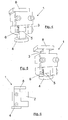
- Figures 1 to 3 show a particular embodiment of the measuring tool 1 for the measuring the levels of leak-tightness in side doors with closure in vertical plane
- Figures 4 to 6 show a particular embodiment of the measuring tool 1 for measuring the levels of leak-tightness measurement in boot lids with closure in horizontal plane.
- the measuring tool 1 has a metal part or element for tightening clearances between the sliding element 3 and the fixed block.
- Figure 9 shows the fixing of the measuring tool 1 in the flange of the edge of a boot lid
- Figure 10 shows the fixing of a measuring tool 1 in the flange of the edge of a door.
- the set of tools for measuring the levels of leak-tightness has a levelling stop 7 which is also substantially prismatic, and which is located close to the measuring tool 1, acting as a stop between the edge of the body and the edge of the moving element, and preventing the edge of the moving element from getting close to the body beyond a pre-established level.
- This levelling stop 7 also has a fixing housing 2, in which there is inserted the flange of the edge of the body of the area in which the moving element closes.
- the levelling stop 7 also has a plurality of magnets therein for fixing the levelling stop 1 to the body.
- Figure 11 shows the fixing of a levelling stop 7 to the flange of the edge of a boot lid.
- the measuring tool 1 is preferably made of steel to increase its resistance and prevent its wear.
- the measuring tool 1 additionally has protections in its areas contacting the body and the edge of the moving element. Specifically, for avoiding damage such as scratches, portions of soft, non-deformable material, such as for example, resin, nylon, Teflon, etc., are fixed at the end 4 of the sliding element 3.
- the levelling stop 7 is made of resin, said material providing the stop with the necessary resistance, and at the same time preventing the body and the moving element from being damaged when they abut against this levelling stop 7.
- the magnets of the measuring tool 1 and of the levelling stop 7 are cylindrical, being arranged inside the measuring tool 1 and the levelling stop 7.
Abstract
Description
- The present invention belongs to the technical field of automotive, specifically to the technical field of assembling automobile body, and more specifically to assembling, controlling and checking moving closure elements in the body. Although the possibility of using same in different industries requiring leak-tightness control or element closure is not dismissed, the present invention particufariy relates to a set of tools for measuring the levels of assembly and leak-tightness in moving door and boot lid elements assembled in the bodies.
- The harsh quality controls existing today in the automotive sector means that the clearance or levels of leak-tightness existing between moving closure elements when they are closed and the body, i.e., the distance between the edge of the closed door or boot lid and the body is exhaustively controlled.
- The level of leak-tightness is the measurement ensuring both the hardness of dousing the doors, bonnet and boot lid, and the possible entry of water into the cabin of the vehicle, and it also assures the appearance of the elements by assuring their fit.
- The stability of said level must be assured for ensuring the viability of the project and its functionality.
- It is fundamental that this level is within the pre-established limits, since said clearances or levels will be closed by means of a rubber seal with a predetermined width.
- Currently, many of these levels of leak-tightness or clearances are measured by means of a conventional calliper. For taking many of these measurements, the operator must enter the body, which can cause damage to different elements of the automobile.
- Some clearances cannot be measured with the calliper due to their configuration or their shape. In these cases, the operators tend to use templates made of mouldable materials or already marked conical parts for measuring the level of leak-tightness which, in addition to increases its costs, greatly slows down the measurement taking process.
- Measuring means achieving an efficient measurement of the levels of leak-tightness or clearances between moving closure elements and the body, preventing the drawbacks existing in the above measuring means of the state of the art were therefore desirable.
- The present invention solves the problems existing in the state of the art by means of a set of tools for measuring the levels of leak-tightness in moving elements assembled in automobile bodies. These moving elements assembled in bodies refer to closure elements, mainly doors and boot lids of the automobile, and the level of assembly or level of leak-tightness refers to the clearance remaining between the edge of the door or boot lid once closed and the edge of the adjacent body.
- This set of tools for measuring the levels of leak-tightness is formed by a measuring tool and by a levelling stop.
- The measuring tool is substantially prismatic and has a fixing housing in which there is inserted the flange of the edge of the body of the area in which the moving element closes. Likewise, the measuring tool has magnets or clips for fixing the measuring tool to the body.
- The measuring tool also has a sliding element traversing it and it is movable longitudinally through same. This sliding element has an end and a safety stop contacting the body and the edge of the moving element respectively. The sliding element has a mark between the end and the safety stop which provides the level measurement on a graduated scale provided in the measuring tool, both elements forming a nonius.
- The levelling stop is also substantially prismatic and acts as a stop between the edge of the body and the edge of the moving element, thus preventing the edge of the moving element from getting close to the body beyond a pre-established level, thus operating as a levelling element. The levelling stop has another fixing housing, in which there is also inserted the flange of the edge of the body of the area in which the moving element closes, and it also has magnets or clips for fixing said levelling stop to the body.
- Thus, by means of this set of tools for measuring the level of leak-tightness the reading of the results obtained is direct and easy to interpret.
- Furthermore, the work of the operator is facilitated since he/she does not have to enter it preventing possible damage inside the body during measurement taking.
- For taking the measurement by means of the set of measuring tools of the present invention, first the measuring tool is assembled in the area to be measured, between the body and the edge of the moving element, either a door or boot lid. The measuring tool is assembled by means of the fixing housing in which there is introduced the body (fixed part) with the position of the sliding element at its maximum travel. The levelling stop is then assembled for assuring the levelling of the moving element in the body, preventing its clearance from exceeding a certain pre-established value. Once the levelling stop is assembled both the body and the moving element will exert pressure on the measuring tool, causing the sliding element to move until its end and safety stop contact the body and the moving element respectively, the nonius formed by the graduated scale and the mark marking a specific measurement.
- Therefore, productivity and ergonomics improvement with respect to the current way of measuring, flexibility of measuring with this means because it can be performed without any type of installation and production control and analysis speed can be highlighted among the advantages offered by the present invention.
- To better understand the invention, an embodiment of the invention referring to a set of drawings will be described below in an illustrative but non-limiting manner.
-
Figure 1 is a perspective view of a particular embodiment of a measuring tool object of the present invention in a first measurement position showing the ends of the sliding element. -
Figure 2 is a perspective view of the measuring tool ofFigure 1 in a second measurement position in which the sliding element has been moved. -
Figure 3 is a view of the measuring tool ofFigures 1 and 2 showing the fixing housing. -
Figure 4 is a perspective view of a different embodiment of a measuring tool object of the present invention in a first measurement position showing the ends of the sliding element. -
Figure 5 is a perspective view of the measuring tool ofFigure 4 in a second measurement position in which the sliding element has been moved. -
Figure 6 is a side view of the measuring tool ofFigures 4 and 5 showing the fixing housing. -
Figure 7 is a perspective view of an embodiment of the levelling stop object of the present invention. -
Figure 8 is a side view of the levelling stop ofFigure 7 showing the fixing housing. -
Figure 9 is a schematic view showing a measuring tool fixed to the edge of a boot lid showing how the flange of the edge is housed in the fixing housing. -
Figure 10 is a schematic view showing a measuring tool fixed to the edge of as door. -
Figure 11 is a schematic view showing a levelling stop housed in a boot lid. - These drawings refer to a set of elements including:
- 1. measuring tool
- 2. fixing housing
- 3. sliding element of the measuring tool
- 4. end of the sliding element
- 5. intermediate mark of the sliding element
- 6. graduated scale
- 7. levelling stop
- 8. safety stop
- The object of the-present invention is a set of tools for measuring the levels of leak-tightness in moving elements assembled in automobile bodies. These moving elements are closure elements of the body, mainly doors and boot lids, the level of assembly or the level of leak-tightness being the clearance existing between the edge of the door or boot lid once closed and the edge of the body in which it is arranged.
- As can be seen in
Figures 1 to 6 , the set of tools for measuring the levels of leak-tightness object of the present invention has a substantiallyprismatic measuring tool 1 which in turn has a fixinghousing 2, in which there is inserted the flange of the edge of the body of the area in which the moving element closes. Furthermore, the measuring tool has magnets for fixing themeasuring tool 1 to the body by means of magnetic forces. The measuringtool 1 has a slidingelement 3 for level measurement which traverses the measuringtool 1, being longitudinally movable through said measuringtool 1. This slidingelement 3 has anend 4 and asafety stop 8, one of them contacting the body and the other the edge of the moving element. Depending of the existing clearance, the slidingelement 3 is moved along the inside of the prismatic body of themeasuring tool 1, until both ends contact the body and the edge of the moving element respectively. Amark 5 in the slidingelement 3, provided at an intermediate point between theend 4 and thesafety stop 8 provides the level measurement on a graduatedscale 6 depicted on a surface of themeasuring tool 1, both elements forming a nonius. -
Figures 1 to 3 show a particular embodiment of themeasuring tool 1 for the measuring the levels of leak-tightness in side doors with closure in vertical plane, whileFigures 4 to 6 show a particular embodiment of themeasuring tool 1 for measuring the levels of leak-tightness measurement in boot lids with closure in horizontal plane. The measuringtool 1 has a metal part or element for tightening clearances between the slidingelement 3 and the fixed block. -
Figure 9 shows the fixing of themeasuring tool 1 in the flange of the edge of a boot lid, whileFigure 10 shows the fixing of ameasuring tool 1 in the flange of the edge of a door. - Additionally, as seen in
Figures 7 to 8 , the set of tools for measuring the levels of leak-tightness has a levellingstop 7 which is also substantially prismatic, and which is located close to themeasuring tool 1, acting as a stop between the edge of the body and the edge of the moving element, and preventing the edge of the moving element from getting close to the body beyond a pre-established level. This levellingstop 7 also has a fixinghousing 2, in which there is inserted the flange of the edge of the body of the area in which the moving element closes. The levellingstop 7 also has a plurality of magnets therein for fixing the levellingstop 1 to the body. -
Figure 11 shows the fixing of a levellingstop 7 to the flange of the edge of a boot lid. - The measuring
tool 1 is preferably made of steel to increase its resistance and prevent its wear. The measuringtool 1 additionally has protections in its areas contacting the body and the edge of the moving element. Specifically, for avoiding damage such as scratches, portions of soft, non-deformable material, such as for example, resin, nylon, Teflon, etc., are fixed at theend 4 of the slidingelement 3. - The levelling
stop 7 is made of resin, said material providing the stop with the necessary resistance, and at the same time preventing the body and the moving element from being damaged when they abut against this levellingstop 7. - According to a preferred embodiment of the invention, the magnets of the
measuring tool 1 and of the levellingstop 7 are cylindrical, being arranged inside the measuringtool 1 and the levellingstop 7. - Having clearly described the invention, it is must be stated that the particular embodiments described above are susceptible to detail modifications as long as they do not alter the fundamental principal and the essence of the invention.
Claims (4)
- A set of tools for measuring the levels of leak-tightness in moving elements assembled in automobile bodies, the moving elements being doors and boot lids, said set characterised in that it comprises- a substantially prismatic measuring tool (1), comprising.- a fixing housing (2) in which there is inserted the flange of the edge of the body of the area in which the moving element closes- a plurality of magnets for fixing the measuring tool (1) to the body,- and a sliding element (3) traversing the measuring tool (1) and is movable longitudinally through said measuring tool (1), comprising- an end (4) and a safety stop (8), which contact respectively with the body and the edge of the moving element respectively, and- a mark (5) between both ends (4) providing the level measurement on- a graduated scale (6) provided in the measuring tool (1), and- a substantially prismatic levelling stop (7) acting as a stop between the edge of the body and the edge of the moving element, preventing the edge of the moving element from getting close to the body beyond a pre-established level, said levelling stop (7) comprising- a fixing housing (2) in which there is inserted the flange of the edge of the body of the area in which the moving element closes close to the measuring tool (1), and- a plurality of magnets for fixing the levelling stop (1) to the body.
- The set of tools for measuring the levels of leak-tightness in moving elements assembled in automobile bodies according to claim 1, characterised in that- the measuring tool (1) is made of steel,- and in that the end (4) of the sliding element (3) comprises soft non-deformable material selected from resin, nylon, Teflon, and combination thereof.
- The set of tools for measuring the levels of leak-tightness in moving elements assembled in automobile bodies according to any of the preceding claims, characterised in that the levelling stop (7) is made of resin.
- The set of tools for measuring the levels of leak-tightness in moving elements assembled in automobile bodies according to any of the preceding claims, characterised in that the magnets of the measuring tool (1) are cylindrical and are arranged inside said measuring tool (1).
Applications Claiming Priority (1)
| Application Number | Priority Date | Filing Date | Title |
|---|---|---|---|
| ES201131328U ES1076156Y (en) | 2011-12-26 | 2011-12-26 | SET OF TOOLS FOR THE MEASUREMENT OF SEALING DIMENSIONS IN MOBILE ELEMENTS MOUNTED IN CAR BODIES. |
Publications (2)
| Publication Number | Publication Date |
|---|---|
| EP2610579A1 true EP2610579A1 (en) | 2013-07-03 |
| EP2610579B1 EP2610579B1 (en) | 2015-09-30 |
Family
ID=45509851
Family Applications (1)
| Application Number | Title | Priority Date | Filing Date |
|---|---|---|---|
| EP12382286.8A Not-in-force EP2610579B1 (en) | 2011-12-26 | 2012-07-19 | Set of tools for measuring the levels of leak-tightness in moving elements assembled in automobile bodies |
Country Status (2)
| Country | Link |
|---|---|
| EP (1) | EP2610579B1 (en) |
| ES (2) | ES1076156Y (en) |
Cited By (7)
| Publication number | Priority date | Publication date | Assignee | Title |
|---|---|---|---|---|
| DE102013220198A1 (en) * | 2013-10-07 | 2015-04-09 | Bayerische Motoren Werke Aktiengesellschaft | Car window Teaching |
| DE102014226312A1 (en) * | 2014-12-17 | 2016-06-23 | Bayerische Motoren Werke Aktiengesellschaft | Tester |
| FR3044754A1 (en) * | 2015-12-03 | 2017-06-09 | Peugeot Citroen Automobiles Sa | CHECKING TEMPLATE OF THE POSITION OF AN EDGE OF LECHE CREEP GLASS OF A VEHICLE OF A MOTOR VEHICLE |
| WO2019038538A1 (en) * | 2017-08-23 | 2019-02-28 | Paragon Inspection Limited | Connector assembly evaluation tool and method |
| DE102017216474A1 (en) | 2017-09-18 | 2019-03-21 | Audi Ag | Measuring device and method for measuring the inside air on a vehicle flap or vehicle door |
| US10571235B2 (en) | 2018-03-07 | 2020-02-25 | Honda Motor Co., Ltd. | Flange check tool |
| US10589811B2 (en) | 2018-03-22 | 2020-03-17 | Honda Motor Co., Ltd | Door hem length measurement tool |
Families Citing this family (1)
| Publication number | Priority date | Publication date | Assignee | Title |
|---|---|---|---|---|
| US10487557B2 (en) | 2017-03-17 | 2019-11-26 | Honda Motor Co., Ltd. | Measurement systems and methods for vehicle window assemblies |
Citations (5)
| Publication number | Priority date | Publication date | Assignee | Title |
|---|---|---|---|---|
| DE10015155A1 (en) * | 2000-03-27 | 2001-10-18 | Metronom Indvermessung Gmbh | Device and method for measuring gap widths and mechanical tension, e.g. for measuring gaps in doors during car bodywork production, applies a flexible element under tension into a gap as well as a distance retainer |
| US20020052710A1 (en) * | 2000-10-30 | 2002-05-02 | Woo-Dong Hwang | Method for measuring door sealing gap of vehicle |
| EP1671876A2 (en) * | 2004-12-16 | 2006-06-21 | MT Misslbeck Technologies GmbH | Method and device to check the gap between a vehicle body and doors or lids attached thereto |
| KR20070059661A (en) * | 2005-12-07 | 2007-06-12 | 기아자동차주식회사 | Seal gap measuring method of automobile |
| DE102007060820A1 (en) * | 2007-12-18 | 2009-06-25 | Daimler Ag | Measuring device for determining distance between opened vehicle door or flap of motor vehicle and car body of motor vehicle, has measuring scale dividing axial along base body |
-
2011
- 2011-12-26 ES ES201131328U patent/ES1076156Y/en not_active Expired - Fee Related
-
2012
- 2012-07-19 EP EP12382286.8A patent/EP2610579B1/en not_active Not-in-force
- 2012-07-19 ES ES12382286.8T patent/ES2556486T3/en active Active
Patent Citations (5)
| Publication number | Priority date | Publication date | Assignee | Title |
|---|---|---|---|---|
| DE10015155A1 (en) * | 2000-03-27 | 2001-10-18 | Metronom Indvermessung Gmbh | Device and method for measuring gap widths and mechanical tension, e.g. for measuring gaps in doors during car bodywork production, applies a flexible element under tension into a gap as well as a distance retainer |
| US20020052710A1 (en) * | 2000-10-30 | 2002-05-02 | Woo-Dong Hwang | Method for measuring door sealing gap of vehicle |
| EP1671876A2 (en) * | 2004-12-16 | 2006-06-21 | MT Misslbeck Technologies GmbH | Method and device to check the gap between a vehicle body and doors or lids attached thereto |
| KR20070059661A (en) * | 2005-12-07 | 2007-06-12 | 기아자동차주식회사 | Seal gap measuring method of automobile |
| DE102007060820A1 (en) * | 2007-12-18 | 2009-06-25 | Daimler Ag | Measuring device for determining distance between opened vehicle door or flap of motor vehicle and car body of motor vehicle, has measuring scale dividing axial along base body |
Cited By (10)
| Publication number | Priority date | Publication date | Assignee | Title |
|---|---|---|---|---|
| DE102013220198A1 (en) * | 2013-10-07 | 2015-04-09 | Bayerische Motoren Werke Aktiengesellschaft | Car window Teaching |
| DE102014226312A1 (en) * | 2014-12-17 | 2016-06-23 | Bayerische Motoren Werke Aktiengesellschaft | Tester |
| FR3044754A1 (en) * | 2015-12-03 | 2017-06-09 | Peugeot Citroen Automobiles Sa | CHECKING TEMPLATE OF THE POSITION OF AN EDGE OF LECHE CREEP GLASS OF A VEHICLE OF A MOTOR VEHICLE |
| WO2019038538A1 (en) * | 2017-08-23 | 2019-02-28 | Paragon Inspection Limited | Connector assembly evaluation tool and method |
| GB2567924B (en) * | 2017-08-23 | 2022-04-13 | Paragon Inspection Ltd | Connector assembly evaluation tool and method |
| US11703312B2 (en) | 2017-08-23 | 2023-07-18 | Paragon Inspection Limited | Connector assembly evaluation tool and method |
| AU2018319635B2 (en) * | 2017-08-23 | 2023-07-27 | Paragon Inspection Limited | Connector assembly evaluation tool and method |
| DE102017216474A1 (en) | 2017-09-18 | 2019-03-21 | Audi Ag | Measuring device and method for measuring the inside air on a vehicle flap or vehicle door |
| US10571235B2 (en) | 2018-03-07 | 2020-02-25 | Honda Motor Co., Ltd. | Flange check tool |
| US10589811B2 (en) | 2018-03-22 | 2020-03-17 | Honda Motor Co., Ltd | Door hem length measurement tool |
Also Published As
| Publication number | Publication date |
|---|---|
| EP2610579B1 (en) | 2015-09-30 |
| ES2556486T3 (en) | 2016-01-18 |
| ES1076156U (en) | 2012-02-10 |
| ES1076156Y (en) | 2012-05-10 |
Similar Documents
| Publication | Publication Date | Title |
|---|---|---|
| EP2610579B1 (en) | Set of tools for measuring the levels of leak-tightness in moving elements assembled in automobile bodies | |
| US9335144B2 (en) | Hole depth measurement device | |
| EP1671876B1 (en) | Method and device to check the gap between a vehicle body and doors or lids attached thereto | |
| DE102007030496A1 (en) | Motor vehicle e.g. delivery van, has closure lid position sensor matched with drive device such that position sensor is integrated in luggage compartment closure lid and position of closure lid is detected at region | |
| DE102017207814A1 (en) | Swivel bearing with seal arrangement | |
| DE102017215340A1 (en) | Method for checking a contacting of a pantograph and pantograph | |
| EP3365574B1 (en) | Ball joint with wear measuring device | |
| CN105841585A (en) | Gap measurement tool and gap qualified rate measurement method | |
| KR200488152Y1 (en) | Energy guide chain for machine tools for machining workpieces | |
| US20180106013A1 (en) | Moldboard wear strip | |
| EP1813564B1 (en) | Device for generating shaft information | |
| CN109443164A (en) | Body hinge detecting tool | |
| DE102007060820A1 (en) | Measuring device for determining distance between opened vehicle door or flap of motor vehicle and car body of motor vehicle, has measuring scale dividing axial along base body | |
| DE102010008772A1 (en) | Rotary bearing for wheel of e.g. passenger car, has measuring rod facing sensor that is connected with inner ring in torque-proof manner for measuring rotation of wheel of motor vehicle, where sensor is secured in recess in inner ring | |
| CN204457174U (en) | Vehicle doorn snap fastening device and there is its vehicle | |
| DE102017003075B4 (en) | Measuring system for determining the angle of rotation | |
| EP3851243B1 (en) | Method using a device for machining a workpiece | |
| FI68889B (en) | SAETESVENTIL | |
| DE102014107267A1 (en) | Encoder for power clamps | |
| CN108747580B (en) | Automatic hidden tool setting device of horizontal machining center | |
| CN212378939U (en) | Auxiliary positioning device for detecting opening and closing force of door leaf of civil air defense door | |
| CN209763924U (en) | Utensil is examined to white automobile body and back door's cooperation precision | |
| JP7456870B2 (en) | Measuring and Inspecting Tools | |
| DE102017216474B4 (en) | Measuring equipment and methods for indoor air measurement on a vehicle flap or vehicle door | |
| CN212122572U (en) | Sealing structure of protective door of machine tool |
Legal Events
| Date | Code | Title | Description |
|---|---|---|---|
| PUAI | Public reference made under article 153(3) epc to a published international application that has entered the european phase |
Free format text: ORIGINAL CODE: 0009012 |
|
| AK | Designated contracting states |
Kind code of ref document: A1 Designated state(s): AL AT BE BG CH CY CZ DE DK EE ES FI FR GB GR HR HU IE IS IT LI LT LU LV MC MK MT NL NO PL PT RO RS SE SI SK SM TR |
|
| AX | Request for extension of the european patent |
Extension state: BA ME |
|
| 17P | Request for examination filed |
Effective date: 20131224 |
|
| RBV | Designated contracting states (corrected) |
Designated state(s): AL AT BE BG CH CY CZ DE DK EE ES FI FR GB GR HR HU IE IS IT LI LT LU LV MC MK MT NL NO PL PT RO RS SE SI SK SM TR |
|
| GRAP | Despatch of communication of intention to grant a patent |
Free format text: ORIGINAL CODE: EPIDOSNIGR1 |
|
| RIC1 | Information provided on ipc code assigned before grant |
Ipc: G01B 3/20 20060101AFI20150519BHEP Ipc: G01B 5/14 20060101ALI20150519BHEP Ipc: B62D 65/00 20060101ALI20150519BHEP |
|
| INTG | Intention to grant announced |
Effective date: 20150612 |
|
| GRAS | Grant fee paid |
Free format text: ORIGINAL CODE: EPIDOSNIGR3 |
|
| GRAA | (expected) grant |
Free format text: ORIGINAL CODE: 0009210 |
|
| AK | Designated contracting states |
Kind code of ref document: B1 Designated state(s): AL AT BE BG CH CY CZ DE DK EE ES FI FR GB GR HR HU IE IS IT LI LT LU LV MC MK MT NL NO PL PT RO RS SE SI SK SM TR |
|
| REG | Reference to a national code |
Ref country code: CH Ref legal event code: EP Ref country code: GB Ref legal event code: FG4D |
|
| REG | Reference to a national code |
Ref country code: AT Ref legal event code: REF Ref document number: 752669 Country of ref document: AT Kind code of ref document: T Effective date: 20151015 |
|
| REG | Reference to a national code |
Ref country code: IE Ref legal event code: FG4D |
|
| REG | Reference to a national code |
Ref country code: DE Ref legal event code: R096 Ref document number: 602012011088 Country of ref document: DE |
|
| REG | Reference to a national code |
Ref country code: ES Ref legal event code: FG2A Ref document number: 2556486 Country of ref document: ES Kind code of ref document: T3 Effective date: 20160118 |
|
| PG25 | Lapsed in a contracting state [announced via postgrant information from national office to epo] |
Ref country code: LT Free format text: LAPSE BECAUSE OF FAILURE TO SUBMIT A TRANSLATION OF THE DESCRIPTION OR TO PAY THE FEE WITHIN THE PRESCRIBED TIME-LIMIT Effective date: 20150930 Ref country code: NO Free format text: LAPSE BECAUSE OF FAILURE TO SUBMIT A TRANSLATION OF THE DESCRIPTION OR TO PAY THE FEE WITHIN THE PRESCRIBED TIME-LIMIT Effective date: 20151230 Ref country code: GR Free format text: LAPSE BECAUSE OF FAILURE TO SUBMIT A TRANSLATION OF THE DESCRIPTION OR TO PAY THE FEE WITHIN THE PRESCRIBED TIME-LIMIT Effective date: 20151231 Ref country code: FI Free format text: LAPSE BECAUSE OF FAILURE TO SUBMIT A TRANSLATION OF THE DESCRIPTION OR TO PAY THE FEE WITHIN THE PRESCRIBED TIME-LIMIT Effective date: 20150930 Ref country code: LV Free format text: LAPSE BECAUSE OF FAILURE TO SUBMIT A TRANSLATION OF THE DESCRIPTION OR TO PAY THE FEE WITHIN THE PRESCRIBED TIME-LIMIT Effective date: 20150930 |
|
| REG | Reference to a national code |
Ref country code: NL Ref legal event code: MP Effective date: 20150930 |
|
| REG | Reference to a national code |
Ref country code: LT Ref legal event code: MG4D |
|
| REG | Reference to a national code |
Ref country code: AT Ref legal event code: MK05 Ref document number: 752669 Country of ref document: AT Kind code of ref document: T Effective date: 20150930 |
|
| PG25 | Lapsed in a contracting state [announced via postgrant information from national office to epo] |
Ref country code: RS Free format text: LAPSE BECAUSE OF FAILURE TO SUBMIT A TRANSLATION OF THE DESCRIPTION OR TO PAY THE FEE WITHIN THE PRESCRIBED TIME-LIMIT Effective date: 20150930 Ref country code: SE Free format text: LAPSE BECAUSE OF FAILURE TO SUBMIT A TRANSLATION OF THE DESCRIPTION OR TO PAY THE FEE WITHIN THE PRESCRIBED TIME-LIMIT Effective date: 20150930 Ref country code: HR Free format text: LAPSE BECAUSE OF FAILURE TO SUBMIT A TRANSLATION OF THE DESCRIPTION OR TO PAY THE FEE WITHIN THE PRESCRIBED TIME-LIMIT Effective date: 20150930 |
|
| PG25 | Lapsed in a contracting state [announced via postgrant information from national office to epo] |
Ref country code: EE Free format text: LAPSE BECAUSE OF FAILURE TO SUBMIT A TRANSLATION OF THE DESCRIPTION OR TO PAY THE FEE WITHIN THE PRESCRIBED TIME-LIMIT Effective date: 20150930 Ref country code: IS Free format text: LAPSE BECAUSE OF FAILURE TO SUBMIT A TRANSLATION OF THE DESCRIPTION OR TO PAY THE FEE WITHIN THE PRESCRIBED TIME-LIMIT Effective date: 20160130 Ref country code: SK Free format text: LAPSE BECAUSE OF FAILURE TO SUBMIT A TRANSLATION OF THE DESCRIPTION OR TO PAY THE FEE WITHIN THE PRESCRIBED TIME-LIMIT Effective date: 20150930 Ref country code: CZ Free format text: LAPSE BECAUSE OF FAILURE TO SUBMIT A TRANSLATION OF THE DESCRIPTION OR TO PAY THE FEE WITHIN THE PRESCRIBED TIME-LIMIT Effective date: 20150930 Ref country code: NL Free format text: LAPSE BECAUSE OF FAILURE TO SUBMIT A TRANSLATION OF THE DESCRIPTION OR TO PAY THE FEE WITHIN THE PRESCRIBED TIME-LIMIT Effective date: 20150930 |
|
| PG25 | Lapsed in a contracting state [announced via postgrant information from national office to epo] |
Ref country code: PL Free format text: LAPSE BECAUSE OF FAILURE TO SUBMIT A TRANSLATION OF THE DESCRIPTION OR TO PAY THE FEE WITHIN THE PRESCRIBED TIME-LIMIT Effective date: 20150930 Ref country code: RO Free format text: LAPSE BECAUSE OF FAILURE TO SUBMIT A TRANSLATION OF THE DESCRIPTION OR TO PAY THE FEE WITHIN THE PRESCRIBED TIME-LIMIT Effective date: 20150930 Ref country code: PT Free format text: LAPSE BECAUSE OF FAILURE TO SUBMIT A TRANSLATION OF THE DESCRIPTION OR TO PAY THE FEE WITHIN THE PRESCRIBED TIME-LIMIT Effective date: 20160201 Ref country code: AT Free format text: LAPSE BECAUSE OF FAILURE TO SUBMIT A TRANSLATION OF THE DESCRIPTION OR TO PAY THE FEE WITHIN THE PRESCRIBED TIME-LIMIT Effective date: 20150930 |
|
| REG | Reference to a national code |
Ref country code: DE Ref legal event code: R097 Ref document number: 602012011088 Country of ref document: DE |
|
| REG | Reference to a national code |
Ref country code: FR Ref legal event code: PLFP Year of fee payment: 5 |
|
| PLBE | No opposition filed within time limit |
Free format text: ORIGINAL CODE: 0009261 |
|
| STAA | Information on the status of an ep patent application or granted ep patent |
Free format text: STATUS: NO OPPOSITION FILED WITHIN TIME LIMIT |
|
| PG25 | Lapsed in a contracting state [announced via postgrant information from national office to epo] |
Ref country code: DK Free format text: LAPSE BECAUSE OF FAILURE TO SUBMIT A TRANSLATION OF THE DESCRIPTION OR TO PAY THE FEE WITHIN THE PRESCRIBED TIME-LIMIT Effective date: 20150930 |
|
| 26N | No opposition filed |
Effective date: 20160701 |
|
| PGFP | Annual fee paid to national office [announced via postgrant information from national office to epo] |
Ref country code: GB Payment date: 20160729 Year of fee payment: 5 Ref country code: IT Payment date: 20160725 Year of fee payment: 5 |
|
| PG25 | Lapsed in a contracting state [announced via postgrant information from national office to epo] |
Ref country code: SI Free format text: LAPSE BECAUSE OF FAILURE TO SUBMIT A TRANSLATION OF THE DESCRIPTION OR TO PAY THE FEE WITHIN THE PRESCRIBED TIME-LIMIT Effective date: 20150930 |
|
| PGFP | Annual fee paid to national office [announced via postgrant information from national office to epo] |
Ref country code: FR Payment date: 20160728 Year of fee payment: 5 |
|
| PG25 | Lapsed in a contracting state [announced via postgrant information from national office to epo] |
Ref country code: BE Free format text: LAPSE BECAUSE OF FAILURE TO SUBMIT A TRANSLATION OF THE DESCRIPTION OR TO PAY THE FEE WITHIN THE PRESCRIBED TIME-LIMIT Effective date: 20150930 |
|
| REG | Reference to a national code |
Ref country code: CH Ref legal event code: PL |
|
| PG25 | Lapsed in a contracting state [announced via postgrant information from national office to epo] |
Ref country code: MC Free format text: LAPSE BECAUSE OF FAILURE TO SUBMIT A TRANSLATION OF THE DESCRIPTION OR TO PAY THE FEE WITHIN THE PRESCRIBED TIME-LIMIT Effective date: 20150930 |
|
| PG25 | Lapsed in a contracting state [announced via postgrant information from national office to epo] |
Ref country code: LI Free format text: LAPSE BECAUSE OF NON-PAYMENT OF DUE FEES Effective date: 20160731 Ref country code: CH Free format text: LAPSE BECAUSE OF NON-PAYMENT OF DUE FEES Effective date: 20160731 |
|
| REG | Reference to a national code |
Ref country code: IE Ref legal event code: MM4A |
|
| PG25 | Lapsed in a contracting state [announced via postgrant information from national office to epo] |
Ref country code: IE Free format text: LAPSE BECAUSE OF NON-PAYMENT OF DUE FEES Effective date: 20160719 |
|
| PG25 | Lapsed in a contracting state [announced via postgrant information from national office to epo] |
Ref country code: LU Free format text: LAPSE BECAUSE OF NON-PAYMENT OF DUE FEES Effective date: 20160719 |
|
| PGFP | Annual fee paid to national office [announced via postgrant information from national office to epo] |
Ref country code: DE Payment date: 20170929 Year of fee payment: 6 |
|
| GBPC | Gb: european patent ceased through non-payment of renewal fee |
Effective date: 20170719 |
|
| REG | Reference to a national code |
Ref country code: FR Ref legal event code: ST Effective date: 20180330 |
|
| PG25 | Lapsed in a contracting state [announced via postgrant information from national office to epo] |
Ref country code: GB Free format text: LAPSE BECAUSE OF NON-PAYMENT OF DUE FEES Effective date: 20170719 |
|
| PG25 | Lapsed in a contracting state [announced via postgrant information from national office to epo] |
Ref country code: HU Free format text: LAPSE BECAUSE OF FAILURE TO SUBMIT A TRANSLATION OF THE DESCRIPTION OR TO PAY THE FEE WITHIN THE PRESCRIBED TIME-LIMIT; INVALID AB INITIO Effective date: 20120719 Ref country code: FR Free format text: LAPSE BECAUSE OF NON-PAYMENT OF DUE FEES Effective date: 20170731 Ref country code: CY Free format text: LAPSE BECAUSE OF FAILURE TO SUBMIT A TRANSLATION OF THE DESCRIPTION OR TO PAY THE FEE WITHIN THE PRESCRIBED TIME-LIMIT Effective date: 20150930 Ref country code: SM Free format text: LAPSE BECAUSE OF FAILURE TO SUBMIT A TRANSLATION OF THE DESCRIPTION OR TO PAY THE FEE WITHIN THE PRESCRIBED TIME-LIMIT Effective date: 20150930 |
|
| PG25 | Lapsed in a contracting state [announced via postgrant information from national office to epo] |
Ref country code: MK Free format text: LAPSE BECAUSE OF FAILURE TO SUBMIT A TRANSLATION OF THE DESCRIPTION OR TO PAY THE FEE WITHIN THE PRESCRIBED TIME-LIMIT Effective date: 20150930 Ref country code: TR Free format text: LAPSE BECAUSE OF FAILURE TO SUBMIT A TRANSLATION OF THE DESCRIPTION OR TO PAY THE FEE WITHIN THE PRESCRIBED TIME-LIMIT Effective date: 20150930 Ref country code: MT Free format text: LAPSE BECAUSE OF NON-PAYMENT OF DUE FEES Effective date: 20160731 |
|
| PG25 | Lapsed in a contracting state [announced via postgrant information from national office to epo] |
Ref country code: BG Free format text: LAPSE BECAUSE OF FAILURE TO SUBMIT A TRANSLATION OF THE DESCRIPTION OR TO PAY THE FEE WITHIN THE PRESCRIBED TIME-LIMIT Effective date: 20150930 |
|
| PG25 | Lapsed in a contracting state [announced via postgrant information from national office to epo] |
Ref country code: IT Free format text: LAPSE BECAUSE OF NON-PAYMENT OF DUE FEES Effective date: 20170719 |
|
| PG25 | Lapsed in a contracting state [announced via postgrant information from national office to epo] |
Ref country code: AL Free format text: LAPSE BECAUSE OF FAILURE TO SUBMIT A TRANSLATION OF THE DESCRIPTION OR TO PAY THE FEE WITHIN THE PRESCRIBED TIME-LIMIT Effective date: 20150930 |
|
| REG | Reference to a national code |
Ref country code: DE Ref legal event code: R119 Ref document number: 602012011088 Country of ref document: DE |
|
| PG25 | Lapsed in a contracting state [announced via postgrant information from national office to epo] |
Ref country code: DE Free format text: LAPSE BECAUSE OF NON-PAYMENT OF DUE FEES Effective date: 20190201 |
|
| PGFP | Annual fee paid to national office [announced via postgrant information from national office to epo] |
Ref country code: ES Payment date: 20190826 Year of fee payment: 8 |
|
| REG | Reference to a national code |
Ref country code: ES Ref legal event code: FD2A Effective date: 20211230 |
|
| PG25 | Lapsed in a contracting state [announced via postgrant information from national office to epo] |
Ref country code: ES Free format text: LAPSE BECAUSE OF NON-PAYMENT OF DUE FEES Effective date: 20200720 |