EP2610571A1 - Heat exchanger assembly having a distributor tube retainer tab - Google Patents
Heat exchanger assembly having a distributor tube retainer tab Download PDFInfo
- Publication number
- EP2610571A1 EP2610571A1 EP12198624.4A EP12198624A EP2610571A1 EP 2610571 A1 EP2610571 A1 EP 2610571A1 EP 12198624 A EP12198624 A EP 12198624A EP 2610571 A1 EP2610571 A1 EP 2610571A1
- Authority
- EP
- European Patent Office
- Prior art keywords
- manifold
- tab
- retainer
- heat exchanger
- distributor tube
- Prior art date
- Legal status (The legal status is an assumption and is not a legal conclusion. Google has not performed a legal analysis and makes no representation as to the accuracy of the status listed.)
- Granted
Links
Images


Classifications
-
- F—MECHANICAL ENGINEERING; LIGHTING; HEATING; WEAPONS; BLASTING
- F28—HEAT EXCHANGE IN GENERAL
- F28F—DETAILS OF HEAT-EXCHANGE AND HEAT-TRANSFER APPARATUS, OF GENERAL APPLICATION
- F28F9/00—Casings; Header boxes; Auxiliary supports for elements; Auxiliary members within casings
- F28F9/007—Auxiliary supports for elements
- F28F9/013—Auxiliary supports for elements for tubes or tube-assemblies
- F28F9/0131—Auxiliary supports for elements for tubes or tube-assemblies formed by plates
-
- F—MECHANICAL ENGINEERING; LIGHTING; HEATING; WEAPONS; BLASTING
- F28—HEAT EXCHANGE IN GENERAL
- F28F—DETAILS OF HEAT-EXCHANGE AND HEAT-TRANSFER APPARATUS, OF GENERAL APPLICATION
- F28F9/00—Casings; Header boxes; Auxiliary supports for elements; Auxiliary members within casings
- F28F9/02—Header boxes; End plates
- F28F9/026—Header boxes; End plates with static flow control means, e.g. with means for uniformly distributing heat exchange media into conduits
- F28F9/027—Header boxes; End plates with static flow control means, e.g. with means for uniformly distributing heat exchange media into conduits in the form of distribution pipes
- F28F9/0273—Header boxes; End plates with static flow control means, e.g. with means for uniformly distributing heat exchange media into conduits in the form of distribution pipes with multiple holes
-
- F—MECHANICAL ENGINEERING; LIGHTING; HEATING; WEAPONS; BLASTING
- F28—HEAT EXCHANGE IN GENERAL
- F28F—DETAILS OF HEAT-EXCHANGE AND HEAT-TRANSFER APPARATUS, OF GENERAL APPLICATION
- F28F9/00—Casings; Header boxes; Auxiliary supports for elements; Auxiliary members within casings
- F28F9/02—Header boxes; End plates
- F28F9/0246—Arrangements for connecting header boxes with flow lines
-
- F—MECHANICAL ENGINEERING; LIGHTING; HEATING; WEAPONS; BLASTING
- F28—HEAT EXCHANGE IN GENERAL
- F28F—DETAILS OF HEAT-EXCHANGE AND HEAT-TRANSFER APPARATUS, OF GENERAL APPLICATION
- F28F9/00—Casings; Header boxes; Auxiliary supports for elements; Auxiliary members within casings
- F28F9/02—Header boxes; End plates
- F28F9/026—Header boxes; End plates with static flow control means, e.g. with means for uniformly distributing heat exchange media into conduits
- F28F9/027—Header boxes; End plates with static flow control means, e.g. with means for uniformly distributing heat exchange media into conduits in the form of distribution pipes
Definitions
- the present invention relates to a heat exchanger assembly having a distributor tube; more particularly, to a heat exchanger assembly having a distributor tube retainer tab configured to position and retain a distributor tube in a predetermined position.
- a typical automotive heat exchanger assembly includes an inlet manifold, an outlet manifold, and a plurality of extruded multi-port refrigerant tubes hydraulically connecting the inlet and outlet manifolds.
- the core of the heat exchanger assembly is defined by the plurality of refrigerant tubes and corrugated fins disposed between the refrigerant tubes for improved heat transfer efficiency and increased structural rigidity.
- the inlet and outlet manifolds typically extend horizontally while the refrigerant tubes extend vertically with respect to the direction of gravity.
- Distributor tubes are known in the art to be used within inlet manifolds to aid in the even distribution of refrigerant through the core. Also, distributor tubes are known to be used in the outlet manifolds, the upper manifold in evaporative mode, to assist in the collection of refrigerant vapors to reduce the pressure drop through the core of the heat exchanger assemblies.
- a typical distributor tube includes a plurality of apertures axially spaced from one another for dispensing or receiving a refrigerant in a radial direction. The distributor tube is held in position as it extends through the inlet manifold by a braze joint on either ends of the manifold.
- Audible noises are created due to the unconstrained increased length of the distributor tube swaying or vibrating resulting in repeated contact with the inside wall of the manifolds of a modified automotive heat exchanger assembly. Excessive continuous vibrations of the distributor tube may create fatigue fractures to the wall of the manifolds or to the distributor tube itself, as well as damaging the ends of the refrigerant tubes from repeated impacts of the distributor tube to the refrigerant tube ends. There exists a need to reduce the excessive vibrations of the distributor tube to reduce or eliminate audible noise and to prevent damage to the heat exchanger assembly.
- the invention provides for a heat exchanger assembly having a distributor tube retainer tab to hold and maintain a distributor tube in a predetermined position within a manifold of the heat exchanger assembly.
- the heat exchanger assembly includes a first manifold extending along a manifold axis A manifold , in which the first manifold includes a manifold wall having an interior surface defining an interior chamber, an exterior surface opposite of the interior surface, and a retainer slot connecting the interior surface and the exterior surface.
- the retainer slot extends substantially transverse to the manifold axis A mamfold .
- a retainer tab inserted through the retainer slot.
- the retainer tab defines a tab opening configured to engage and maintain the distributor tube within a predetermined position within the interior chamber.
- the tab opening may include a boss extending toward the center of the tab opening to fixably engage the distributor tube.
- the boss may be formed of a vibration reducing material.
- the retainer tab includes a first tab portion that is easily inserted into the retainer slot extending into the interior chamber and a second tab portion having shoulder surfaces contoured to seat onto a surface of the first manifold.
- the retainer tab may also include a third tab portion located between the first tab portion and the second tab portion, in which the third tab portion includes opposite facing end surfaces. The opposite facing end surfaces may be complementary to the corresponding width surfaces of the retainer slot.
- the retainer tab may be interference fitted into the retainer slot.
- the retainer tab provides the advantages of reducing the excessive vibrations of the distributor tube to reduce audible noise and to prevent damage to the ends of the refrigerant tubes; not requiring a braze joint inside the manifold, which would be difficult or impossible to check, to permanently engage the distributor tube; holding the distributor tube in close contact with the inside wall of the header, thereby avoiding interference with the refrigerant tubes; and maintaining the distributor tube in the proper centered location, in applications where the manifold is bent, by restraining the distributor tube during the bending process.
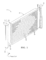
- Shown in Figure 1 is a perspective view of a heat exchanger assembly having the first and second manifolds spaced from the heat exchanger core.
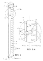
- FIG. 2 Shown in Figure 2 is a perspective cross-sectional view of the first manifold of Figure 1 taken along line 2-2.
- FIG. 2A Shown in Figure 2A is a detail perspective cross-sectional view of the first manifold of Figure 2 showing a retainer tab maintaining a distributor tube in a predetermined position.
- Shown in Figure 3 is a perspective view of the retainer tab of Figure 2A spaced apart from a retainer slot in the first manifold.
- Shown in Figure 4 is a perspective view of an alternative embodiment of a retainer tab spaced apart from a retainer slot in the first manifold.
- first fluid of the exemplary embodiment may be that of a two phase refrigerant and the second fluid may be that of a stream of ambient air. It should be appreciated that other first and second fluids may be used.
- a heat exchanger assembly 20 having a first manifold 22 extending along a manifold axis A manifold between first manifold ends 24.
- the first manifold 22 has an interior surface 26 defining an interior chamber 27, which is best shown in Fig. 2 .
- the first manifold 22 presents a plurality of first tube slots 28 spaced apart from one another along the axis A manifold .
- the heat exchanger assembly 20 also includes a second manifold 30 extending in a spaced and substantially parallel relationship with the first manifold 22.
- the second manifold 30 presents a plurality of second tube slots 32 spaced apart from one another and aligned with the first tube slots 28 of the first manifold 22.
- the first and second manifolds 22, 30 are shown in the vertical orientation with respect to gravity as an illustrative example and it is not meant to be limited as such.
- the first and second manifolds 22, 30 may be tilted from the horizontal direction to the vertical direction with respect to the direction of gravity.
- a heat exchanger core 34 is disposed between the first and second manifolds 22, 30 and includes a plurality of fluid tubes 36 extending into the corresponding first and second tube slots 28, 32 for conveying a fluid, such as a two phase refrigerant, from the first manifold 22 to the second manifold 30.
- the heat exchanger core 34 further includes a plurality of air fins 38 disposed between the fluid tubes 36 for transferring heat between the refrigerant in the tubes 36 and a stream of ambient air. While the heat exchanger core 34 shown has substantially straight fluid tubes 36, the fluid tubes 36 may be bent in any configuration to accommodate for the packaging requirements of the heat exchanger assembly 20 within a given space or for optimizing the drainage of condensate from the heat exchanger core 34.
- FIG. 2 is cross sectional view of the first manifold 22 of the heat exchanger assembly 20 of Fig. 1 .
- a distributor tube 40 is disposed in the interior chamber 27 of the first manifold 22, in which the distributor tube 40 extends along a distributor tube axis A tube .
- Maintaining the distributor tube 40 in a predetermined position within the interior chamber 27 of the first manifold 22 apart from the ends of the fluid tubes 36 is a distributor tube retainer tab 100.
- the retainer tab 100 is configured to be inserted through an elongated retainer slot 42 defined through the wall 23 of first manifold 22, in which the length (L slot ) of the retainer slot 42 extends substantially transverse to the axis A manifold .
- the retainer slot 42 of the first manifold 22 includes a pair of length surfaces 44 and a pair of width surfaces 46 defined in the wall 23 between the interior surface 26 and exterior surface 29 of the first manifold 22.
- a retainer tab 100 configured to restrain the distributor tube 40 to prevent undesirable audible noises as noticed on unrestrained distributor tubes when subjected to vibrations or handling.
- the retainer tab 100 defines a tab opening 101, through which the distributor tube 40 is inserted.
- the tab opening 101 may be that of a generally rounded shape or that of a shape complementary to that of the external cross section shape of the distributor tube 40.
- the tab opening 101 may include a diameter (D) sized to provide an interference fit between the retainer tab 100 and the distributor tube 40 inserted through the tab opening 101.
- the diameter (D) of the tab opening 101 may be slightly larger than the external diameter (d) of the distributor tube 40 and may include at least one boss 112 extending radially toward the center of the tab opening 101.
- the boss 112 is sized to grip onto the distributor tube 40 to fixably engage and maintain the distributor tube 40 onto the retainer tab 100.
- the retainer tab 100 includes a thickness (T tab ) separating a pair of tab surfaces 114, which are oriented in opposite directions.
- the thickness (T tab ) of the retainer tab 100 is substantially that of the thickness (T slot) of the retainer slot 42 defined by the distance between the opposing length surfaces 44, such that the tab surfaces 114 are interference fitted against the length surfaces 44 once the retainer tab 100 is inserted into position within the retainer slot 42.
- the thickness (T slot ) of the retainer slot 42 and corresponding thickness (T tab ) of the retainer tab 100 may not need to be any thicker than the thickness (T wall ) of the wall 23, the distance between the interior surface 26 and exterior surface 29 of the first manifold 22.
- the retainer tab 100 includes a first tab portion 102 having a length (L 1 ) across each of the tab surfaces 114 that is less than the length (L slot )of the retainer slot 42 such that the first tab portion 102 is easily inserted into the retainer slot 42.
- the retainer tab 100 further includes a second tab portion 104 having a length (L 2 ) across each of the tab surfaces 114 that is greater than the length (L slot ) of the retainer slot 42 and defines opposite facing shoulder portions 108.
- Each of the shoulder portions 108 includes a shoulder surface 116 contoured to seat onto the exterior surface 29 of the first manifold 22, as shown in Fig. 3 , or seat onto the width surface 46 of the retainer slot 42, as shown in Fig. 4 , once the retainer tab 100 is inserted into the retainer slot 42 and engaged to the first manifold 22.
- the retainer tab 100 may also include a third tab portion 106 located between the first tab portion 102 and second tab portion 104, in which the third tab portion 106 includes opposite facing end surfaces 110.
- the opposite facing end surfaces 110 are complementary to the corresponding width surfaces 46 of the retainer slot 42.
- the length (L 3 ) across each of the tab surfaces 114 between the end surfaces 110 is substantially the same as that of the length (L slot ) of the retainer slot 42, thereby allowing the third tab portion 106 to be inserted in the retainer slot 42 such that the end surfaces 110 of the retainer tab 100 are interference fitted against the width surfaces 46 of the retainer slot 42.
- the retainer tab 100 may be stamped as a single component from a single or double sided clad aluminum braze sheet, or in the alternative, may be form from non-clad braze sheet for applications where sufficient cladding is available on the first manifold wall 23.
- the retainer tab 100 may be inserted into a preformed retainer slot 42 through the wall 23 of the first manifold 22.
- the distributor tube 40 may then be threaded through the tab opening 101 in the retainer tab 100 using a fixture that contains guides to ensure proper assembly.
- the distributor tube 40 when properly guided by the fixture, reduces the probability of missing the tab opening 101.
- the boss 112 may comprise the same material as that of the retainer tab 100 such as aluminum.
- retainer tabs 100 may be placed in multiple locations along the length of the first manifold 22, to allow better restraint of distributor tubes having excessive lengths, and to keep the distributor tubes centered in the manifolds for applications that require bending of the manifold.
- the design of the retainer tab 100 ensures no contact or interference with the fluid tubes due to the retainer tab's mounting surface being on the opposite side of the manifold from where the fluid tubes enter the manifold.
- the use of the retainer tab 100 provides the advantage of it being used in multiple locations along the length of the manifold for applications where the length of the distributor tube is too long to be only constrained on the ends.
- the retainer tab 100 also provides the advantage tightly gripping the distributor tube, therefore not requiring a braze joint inside the manifold, which would be difficult or impossible to check after the heat exchanger assembly is brazed.
- the retainer tab 100 further provides the advantage or holding the distributor tube in close contact with the inside wall of the manifold, thereby avoiding interference with the fluid tubes. Still furthermore, the retainer tab 100 provides the advantage of maintaining the distributor tube 40 in the proper centered location, in applications where the manifold is bent, by restraining the distributor tube during the bending process.
- the heat exchanger assembly 20 can be used as an evaporator, a condenser, or any other type of heat exchanger construction.
- the heat exchanger assembly 20 of the exemplary embodiment is shown as a one-pass heat exchanger, the fluid distributor tube 40 can also be used in a multi-pass heat exchanger assembly 20.
- the fluid tubes forming the core of the heat exchanger assembly and the manifolds, together or separately, may be bent to accommodate packaging or condensate drainage requirements. While this invention has been described in terms of the preferred embodiments thereof, it is not intended to be so limited, but rather only to the extent set forth in the claims that follow.
Landscapes
- Engineering & Computer Science (AREA)
- Physics & Mathematics (AREA)
- Thermal Sciences (AREA)
- Mechanical Engineering (AREA)
- General Engineering & Computer Science (AREA)
- Heat-Exchange Devices With Radiators And Conduit Assemblies (AREA)
Abstract
Description
- The present invention relates to a heat exchanger assembly having a distributor tube; more particularly, to a heat exchanger assembly having a distributor tube retainer tab configured to position and retain a distributor tube in a predetermined position.
- Air conditioning and heat pump systems for residential and commercial applications are known to employ modified automotive heat exchanger assemblies because of their high heat transfer efficiency, durability, and relatively ease of manufacturability. A typical automotive heat exchanger assembly includes an inlet manifold, an outlet manifold, and a plurality of extruded multi-port refrigerant tubes hydraulically connecting the inlet and outlet manifolds. The core of the heat exchanger assembly is defined by the plurality of refrigerant tubes and corrugated fins disposed between the refrigerant tubes for improved heat transfer efficiency and increased structural rigidity. For residential and commercial applications, the inlet and outlet manifolds typically extend horizontally while the refrigerant tubes extend vertically with respect to the direction of gravity.
- The increased in scale of an automotive heat exchanger assembly for residential and commercial applications dramatically increases the lengths of the inlet and outlet manifolds, which may result in increased refrigerant mal-distribution through the core of the heat exchanger. For heat pump systems, in cooling mode the indoor heat exchanger assembly acts as an evaporator, and in heating mode the outdoor heat exchanger assembly acts as the evaporator. During operation in evaporative mode, a partially expanded two-phase refrigerant enters the lower portions of the refrigerant tubes from the inlet manifold, the lower manifold in evaporative mode, and expands absorbing heat from a stream of ambient air as it rises within the tubes and changing into a vapor phase. Momentum and gravity effects, due to the large mass differences between the liquid and gas phases of the refrigerant, can result in separation of the phases within the inlet manifold and cause poor refrigerant distribution throughout the core of the heat exchanger. Poor refrigerant distribution degrades evaporator performance and can result in uneven temperature distribution over the core.
- Distributor tubes are known in the art to be used within inlet manifolds to aid in the even distribution of refrigerant through the core. Also, distributor tubes are known to be used in the outlet manifolds, the upper manifold in evaporative mode, to assist in the collection of refrigerant vapors to reduce the pressure drop through the core of the heat exchanger assemblies. A typical distributor tube includes a plurality of apertures axially spaced from one another for dispensing or receiving a refrigerant in a radial direction. The distributor tube is held in position as it extends through the inlet manifold by a braze joint on either ends of the manifold.
- Audible noises are created due to the unconstrained increased length of the distributor tube swaying or vibrating resulting in repeated contact with the inside wall of the manifolds of a modified automotive heat exchanger assembly. Excessive continuous vibrations of the distributor tube may create fatigue fractures to the wall of the manifolds or to the distributor tube itself, as well as damaging the ends of the refrigerant tubes from repeated impacts of the distributor tube to the refrigerant tube ends. There exists a need to reduce the excessive vibrations of the distributor tube to reduce or eliminate audible noise and to prevent damage to the heat exchanger assembly.
- The invention provides for a heat exchanger assembly having a distributor tube retainer tab to hold and maintain a distributor tube in a predetermined position within a manifold of the heat exchanger assembly. The heat exchanger assembly includes a first manifold extending along a manifold axis Amanifold, in which the first manifold includes a manifold wall having an interior surface defining an interior chamber, an exterior surface opposite of the interior surface, and a retainer slot connecting the interior surface and the exterior surface. The retainer slot extends substantially transverse to the manifold axis Amamfold. A retainer tab inserted through the retainer slot. The retainer tab defines a tab opening configured to engage and maintain the distributor tube within a predetermined position within the interior chamber. The tab opening may include a boss extending toward the center of the tab opening to fixably engage the distributor tube. The boss may be formed of a vibration reducing material.
- The retainer tab includes a first tab portion that is easily inserted into the retainer slot extending into the interior chamber and a second tab portion having shoulder surfaces contoured to seat onto a surface of the first manifold. The retainer tab may also include a third tab portion located between the first tab portion and the second tab portion, in which the third tab portion includes opposite facing end surfaces. The opposite facing end surfaces may be complementary to the corresponding width surfaces of the retainer slot. The retainer tab may be interference fitted into the retainer slot.
- The retainer tab provides the advantages of reducing the excessive vibrations of the distributor tube to reduce audible noise and to prevent damage to the ends of the refrigerant tubes; not requiring a braze joint inside the manifold, which would be difficult or impossible to check, to permanently engage the distributor tube; holding the distributor tube in close contact with the inside wall of the header, thereby avoiding interference with the refrigerant tubes; and maintaining the distributor tube in the proper centered location, in applications where the manifold is bent, by restraining the distributor tube during the bending process.
- Shown in
Figure 1 is a perspective view of a heat exchanger assembly having the first and second manifolds spaced from the heat exchanger core. - Shown in
Figure 2 is a perspective cross-sectional view of the first manifold ofFigure 1 taken along line 2-2. - Shown in
Figure 2A is a detail perspective cross-sectional view of the first manifold ofFigure 2 showing a retainer tab maintaining a distributor tube in a predetermined position. - Shown in
Figure 3 is a perspective view of the retainer tab ofFigure 2A spaced apart from a retainer slot in the first manifold. - Shown in
Figure 4 is a perspective view of an alternative embodiment of a retainer tab spaced apart from a retainer slot in the first manifold. - Referring to the Figures, wherein like numerals indicate corresponding parts throughout the several views, is an exemplary embodiment of a heat exchanger assembly 20 for transferring heat between a first fluid and a second fluid is generally shown. The first fluid of the exemplary embodiment may be that of a two phase refrigerant and the second fluid may be that of a stream of ambient air. It should be appreciated that other first and second fluids may be used.
- Shown in
Fig. 1 is a heat exchanger assembly 20 having afirst manifold 22 extending along a manifold axis Amanifold betweenfirst manifold ends 24. Thefirst manifold 22 has aninterior surface 26 defining aninterior chamber 27, which is best shown inFig. 2 . Thefirst manifold 22 presents a plurality offirst tube slots 28 spaced apart from one another along the axis Amanifold. The heat exchanger assembly 20 also includes a second manifold 30 extending in a spaced and substantially parallel relationship with thefirst manifold 22. The second manifold 30 presents a plurality of second tube slots 32 spaced apart from one another and aligned with thefirst tube slots 28 of thefirst manifold 22. The first andsecond manifolds 22, 30 are shown in the vertical orientation with respect to gravity as an illustrative example and it is not meant to be limited as such. The first andsecond manifolds 22, 30 may be tilted from the horizontal direction to the vertical direction with respect to the direction of gravity. - A heat exchanger core 34 is disposed between the first and
second manifolds 22, 30 and includes a plurality of fluid tubes 36 extending into the corresponding first andsecond tube slots 28, 32 for conveying a fluid, such as a two phase refrigerant, from thefirst manifold 22 to the second manifold 30. The heat exchanger core 34 further includes a plurality of air fins 38 disposed between the fluid tubes 36 for transferring heat between the refrigerant in the tubes 36 and a stream of ambient air. While the heat exchanger core 34 shown has substantially straight fluid tubes 36, the fluid tubes 36 may be bent in any configuration to accommodate for the packaging requirements of the heat exchanger assembly 20 within a given space or for optimizing the drainage of condensate from the heat exchanger core 34. - Referring to
Fig. 2 is cross sectional view of thefirst manifold 22 of the heat exchanger assembly 20 ofFig. 1 . Adistributor tube 40 is disposed in theinterior chamber 27 of thefirst manifold 22, in which thedistributor tube 40 extends along a distributor tube axis Atube. Maintaining thedistributor tube 40 in a predetermined position within theinterior chamber 27 of thefirst manifold 22 apart from the ends of the fluid tubes 36 is a distributortube retainer tab 100. Shown inFig. 2A , theretainer tab 100 is configured to be inserted through anelongated retainer slot 42 defined through the wall 23 offirst manifold 22, in which the length (Lslot) of theretainer slot 42 extends substantially transverse to the axis Amanifold. Shown inFigs. 3 and4 , theretainer slot 42 of thefirst manifold 22 includes a pair oflength surfaces 44 and a pair ofwidth surfaces 46 defined in the wall 23 between theinterior surface 26 andexterior surface 29 of thefirst manifold 22. - Referring to
Figs. 2A ,3 and4 , is aretainer tab 100 configured to restrain thedistributor tube 40 to prevent undesirable audible noises as noticed on unrestrained distributor tubes when subjected to vibrations or handling. Theretainer tab 100 defines atab opening 101, through which thedistributor tube 40 is inserted. Thetab opening 101 may be that of a generally rounded shape or that of a shape complementary to that of the external cross section shape of thedistributor tube 40. Thetab opening 101 may include a diameter (D) sized to provide an interference fit between theretainer tab 100 and thedistributor tube 40 inserted through thetab opening 101. In the alternative, the diameter (D) of thetab opening 101 may be slightly larger than the external diameter (d) of thedistributor tube 40 and may include at least oneboss 112 extending radially toward the center of thetab opening 101. Theboss 112 is sized to grip onto thedistributor tube 40 to fixably engage and maintain thedistributor tube 40 onto theretainer tab 100. - The
retainer tab 100 includes a thickness (Ttab) separating a pair oftab surfaces 114, which are oriented in opposite directions. The thickness (Ttab) of theretainer tab 100 is substantially that of the thickness (Tslot) of theretainer slot 42 defined by the distance between theopposing length surfaces 44, such that thetab surfaces 114 are interference fitted against thelength surfaces 44 once theretainer tab 100 is inserted into position within theretainer slot 42. The thickness (Tslot) of theretainer slot 42 and corresponding thickness (Ttab) of theretainer tab 100 may not need to be any thicker than the thickness (Twall) of the wall 23, the distance between theinterior surface 26 andexterior surface 29 of thefirst manifold 22. - The
retainer tab 100 includes afirst tab portion 102 having a length (L1) across each of the tab surfaces 114 that is less than the length (Lslot)of theretainer slot 42 such that thefirst tab portion 102 is easily inserted into theretainer slot 42. Theretainer tab 100 further includes asecond tab portion 104 having a length (L2) across each of the tab surfaces 114 that is greater than the length (Lslot) of theretainer slot 42 and defines opposite facingshoulder portions 108. Each of theshoulder portions 108 includes ashoulder surface 116 contoured to seat onto theexterior surface 29 of thefirst manifold 22, as shown inFig. 3 , or seat onto thewidth surface 46 of theretainer slot 42, as shown inFig. 4 , once theretainer tab 100 is inserted into theretainer slot 42 and engaged to thefirst manifold 22. - For a
retainer slot 42 having a pair of substantially opposing width surfaces 46 as shown inFig. 3 , theretainer tab 100 may also include athird tab portion 106 located between thefirst tab portion 102 andsecond tab portion 104, in which thethird tab portion 106 includes opposite facing end surfaces 110. The opposite facing end surfaces 110 are complementary to the corresponding width surfaces 46 of theretainer slot 42. The length (L3) across each of the tab surfaces 114 between the end surfaces 110 is substantially the same as that of the length (Lslot) of theretainer slot 42, thereby allowing thethird tab portion 106 to be inserted in theretainer slot 42 such that the end surfaces 110 of theretainer tab 100 are interference fitted against the width surfaces 46 of theretainer slot 42. - The
retainer tab 100 may be stamped as a single component from a single or double sided clad aluminum braze sheet, or in the alternative, may be form from non-clad braze sheet for applications where sufficient cladding is available on the first manifold wall 23. In manufacturing the heat exchanger assembly 20, theretainer tab 100 may be inserted into a preformedretainer slot 42 through the wall 23 of thefirst manifold 22. Thedistributor tube 40 may then be threaded through thetab opening 101 in theretainer tab 100 using a fixture that contains guides to ensure proper assembly. Thedistributor tube 40, when properly guided by the fixture, reduces the probability of missing thetab opening 101. Theboss 112 may comprise the same material as that of theretainer tab 100 such as aluminum. -
Multiple retainer tabs 100 may be placed in multiple locations along the length of thefirst manifold 22, to allow better restraint of distributor tubes having excessive lengths, and to keep the distributor tubes centered in the manifolds for applications that require bending of the manifold. The design of theretainer tab 100 ensures no contact or interference with the fluid tubes due to the retainer tab's mounting surface being on the opposite side of the manifold from where the fluid tubes enter the manifold. Once theretainer tabs 100,distributor tube 40, andmanifold 22 are assembled together, there is minimal probability of the components coming apart due to handling, shaking, or vibration before the braze operation. - The use of the
retainer tab 100 provides the advantage of it being used in multiple locations along the length of the manifold for applications where the length of the distributor tube is too long to be only constrained on the ends. Theretainer tab 100 also provides the advantage tightly gripping the distributor tube, therefore not requiring a braze joint inside the manifold, which would be difficult or impossible to check after the heat exchanger assembly is brazed. Theretainer tab 100 further provides the advantage or holding the distributor tube in close contact with the inside wall of the manifold, thereby avoiding interference with the fluid tubes. Still furthermore, theretainer tab 100 provides the advantage of maintaining thedistributor tube 40 in the proper centered location, in applications where the manifold is bent, by restraining the distributor tube during the bending process. - It should be appreciated that the heat exchanger assembly 20 can be used as an evaporator, a condenser, or any other type of heat exchanger construction. Additionally, although the heat exchanger assembly 20 of the exemplary embodiment is shown as a one-pass heat exchanger, the
fluid distributor tube 40 can also be used in a multi-pass heat exchanger assembly 20. Furthermore, the fluid tubes forming the core of the heat exchanger assembly and the manifolds, together or separately, may be bent to accommodate packaging or condensate drainage requirements. While this invention has been described in terms of the preferred embodiments thereof, it is not intended to be so limited, but rather only to the extent set forth in the claims that follow.
Claims (14)
- A heat exchanger assembly (20) comprising:a first manifold (22) extending along a manifold axis Amanifold, said first manifold (22) includes a manifold wall (23) having an interior surface (26) defining an interior chamber (27) and an exterior surface (29) opposite of said interior surface (26), wherein said manifold wall (23) defines a retainer slot (42) connecting said interior surface (26) and said exterior surface (29);a distributor tube (40) disposed in said interior chamber (27); anda retainer tab (100) inserted through said retainer slot (42), said retainer tab (100) defines a tab opening (101) configured to engage and maintain said distributor tube (40) within a predetermined position within said interior chamber (27).
- The heat exchanger assembly (20) of claim 1,
wherein said distributor tube (40) includes a distributor tube outer diameter (d);
wherein said tab opening (101) of said retainer tab (100) includes a tab opening diameter (D) greater than said distributor tube outer diameter (d);
wherein said retainer tab (100) includes at least one boss (112) extending radially into said tab opening (101) toward said distributor tube (40), such that said at least one boss (112) fixably engages said distributor tube (40). - The heat exchanger assembly (20) of claim 2, wherein said at least one boss (112) comprises aluminum.
- The heat exchanger assembly (20) of claim 2,
wherein said retainer slot (42) extends substantially transverse to the manifold axis Amanifold and includes a pair of opposing length surfaces (44) and a pair of width surfaces (46);
wherein said retainer tab (100) further includes a first tab portion (102) inserted into said interior chamber (27) through said retainer slot (42) and a second tab portion (104) having opposite facing shoulder portions (108); and
wherein each of said shoulder portion (108) includes a shoulder surface (116) contoured to engage a surface of said first manifold (22), thereby seating said retainer tab (100) in said retainer slot (42). - The heat exchanger assembly (20) of claim 4,
wherein said pair of width surfaces (46) are oriented in the same direction; and
wherein each of said shoulder surface (116) engages respective said width surfaces (46) of said retainer slot (42). - The heat exchanger assembly (20) of claim 4;
wherein said pair of width surfaces (46) are oriented in a substantially opposing direction;
wherein said retainer tab (100) further includes a third tab portion (106) positioned between said first tab portion (102) and said second tab portion (104), said third tab portion (106) includes a pair of substantially opposite facing end surfaces (110) complementary to corresponding said pair of width surfaces (46);
wherein said opposite facing end surfaces (110) engage said width surfaces (46); and
wherein said shoulder surfaces seat on to said exterior surface (29) of said first manifold (22). - A heat exchanger assembly (20) comprising:a first manifold (22) extending along a manifold axis Amanifold, said first manifold (22) includes a manifold wall (23) defining an interior chamber (27) and a retainer slot (42) through said manifold wall (23) substantially transverse to the manifold (22) axis Amamfold;a distributor tube (40) disposed in said interior chamber (27); anda retainer tab (100) inserted through said retainer slot (42), said retainer tab (100) engages and maintains said distributor tube (40) within a predetermined position within said interior chamber (27).
- The heat exchanger assembly (20) of claim 7, wherein said retainer tab (100) includes a first tab portion (102) disposed within said interior chamber (27), said first tab portion (102) defines a tab opening (101) configured to engage and maintain said distributor tube (40) in a predetermined location within said interior chamber (27).
- The heat exchanger assembly (20) of claim 8, wherein said retainer tab (100) further includes a second tab portion (104) engaged onto said exterior surface (29) of said first manifold (22).
- The heat exchanger assembly (20) of claim 9, wherein said retainer tab (100) further includes a third tab portion (106) located between said first tab portion (102) and second tab portion (104), said third tab portion (106) includes a pair of opposite facing end surfaces (110) engaging said wall (23) of said first manifold (22).
- The heat exchanger assembly (20) of claim 9, wherein said retainer tab (100) is interference fitted into said retainer slot (42) against said wall (23) of said first manifold (22).
- A heat exchanger assembly (20) comprising:a first manifold (22) extending along a manifold axis Amanifold, said first manifold (22) includes a manifold wall (23) having an interior surface (26) defining an interior chamber (27) and an exterior surface (29) opposite of said interior surface (26);a distributor tube (40) disposed in said interior chamber (27); anda retainer tab (100) configured to engage and maintain said distributor tube (40) within a predetermined position within said interior chamber (27);wherein said manifold wall (23) defines a retainer slot (42) connecting said interior surface (26) and said exterior surface (29), andwherein said retainer tab (100) is partially inserted through said retainer slot (42).
- The heat exchanger assembly (20) of claim 12,
wherein said retainer slot (42) includes a pair of opposing length surfaces (44) extending substantially transverse to the manifold axis Amanifold and a pair of width surfaces (46) extending substantially parallel to the manifold (22) axis Amanifold;
wherein said retainer tab (100) includes:a pair of opposite facing tab surfaces (114) inference fitted to said pair of opposing length surfaces (44);a first tab portion (102) disposed within said interior chamber (27), said first tab portion (102) includes a tab opening (101) configured to engage and maintain said distributor tube (40) in a predetermined location within said interior chamber (27); anda second tab portion (104) having opposite shoulder surfaces seated onto said first manifold (22). - The heat exchanger assembly (20) of claim 13,
wherein said retainer tab (100) further include a third tab portion (106) located between said first tab portion (102) and second tab portion (104), said third tab portion (106) includes a pair of opposite facing end surfaces (110) inference fitted to said pair of width surfaces (46).
Applications Claiming Priority (2)
| Application Number | Priority Date | Filing Date | Title |
|---|---|---|---|
| US201161581180P | 2011-12-29 | 2011-12-29 | |
| US13/705,411 US9581397B2 (en) | 2011-12-29 | 2012-12-05 | Heat exchanger assembly having a distributor tube retainer tab |
Publications (2)
| Publication Number | Publication Date |
|---|---|
| EP2610571A1 true EP2610571A1 (en) | 2013-07-03 |
| EP2610571B1 EP2610571B1 (en) | 2017-08-02 |
Family
ID=47665824
Family Applications (1)
| Application Number | Title | Priority Date | Filing Date |
|---|---|---|---|
| EP12198624.4A Not-in-force EP2610571B1 (en) | 2011-12-29 | 2012-12-20 | Heat exchanger assembly having a distributor tube retainer tab |
Country Status (3)
| Country | Link |
|---|---|
| US (1) | US9581397B2 (en) |
| EP (1) | EP2610571B1 (en) |
| CN (3) | CN203190718U (en) |
Cited By (2)
| Publication number | Priority date | Publication date | Assignee | Title |
|---|---|---|---|---|
| WO2018100300A1 (en) * | 2016-11-30 | 2018-06-07 | Valeo Systemes Thermiques | Device for distributing a refrigerant inside a collector box of a heat exchanger |
| CN112325673A (en) * | 2020-11-04 | 2021-02-05 | 浙江银轮机械股份有限公司 | Heat exchanger |
Families Citing this family (12)
| Publication number | Priority date | Publication date | Assignee | Title |
|---|---|---|---|---|
| US9581397B2 (en) * | 2011-12-29 | 2017-02-28 | Mahle International Gmbh | Heat exchanger assembly having a distributor tube retainer tab |
| CN105526739B (en) * | 2014-09-29 | 2019-06-14 | 杭州三花研究院有限公司 | A kind of heat exchanger |
| US10551099B2 (en) | 2016-02-04 | 2020-02-04 | Mahle International Gmbh | Micro-channel evaporator having compartmentalized distribution |
| WO2019245334A1 (en) * | 2018-06-21 | 2019-12-26 | 한온시스템 주식회사 | Heat exchanger |
| KR102695168B1 (en) * | 2018-06-21 | 2024-08-14 | 한온시스템 주식회사 | Heat Exchanger |
| US10890386B2 (en) * | 2019-02-01 | 2021-01-12 | Mahle International Gmbh | Evaporator unit including distributor tube and method thereof |
| DE102019002738A1 (en) * | 2019-04-15 | 2020-10-15 | Uhrig Energie Gmbh | Heat exchanger module, heat exchanger system and method for producing the heat exchanger system |
| TWI804772B (en) * | 2020-11-13 | 2023-06-11 | 大陸商深圳興奇宏科技有限公司 | Water-cooling radiator structure with pump |
| CN113513932B (en) * | 2021-04-26 | 2023-07-07 | 浙江银轮机械股份有限公司 | Heat exchanger and system thereof |
| WO2023078462A1 (en) * | 2021-11-08 | 2023-05-11 | 杭州三花微通道换热器有限公司 | Heat exchange assembly and heat exchange system |
| WO2024135191A1 (en) * | 2022-12-23 | 2024-06-27 | 三菱電機株式会社 | Header pipe, heat exchanger, method for manufacturing header pipe, and method for manufacturing heat exchanger |
| KR102942940B1 (en) * | 2023-02-20 | 2026-03-23 | 엘지전자 주식회사 | Heat exchanger |
Citations (3)
| Publication number | Priority date | Publication date | Assignee | Title |
|---|---|---|---|---|
| JPH09166368A (en) * | 1995-12-14 | 1997-06-24 | Sanden Corp | Heat exchanger |
| US20090229805A1 (en) * | 2008-03-13 | 2009-09-17 | Delphi Technologies, Inc. | Manifold design having an improved collector conduit and method of making same |
| WO2011157063A1 (en) * | 2010-06-13 | 2011-12-22 | 三花丹佛斯(杭州)微通道换热器有限公司 | Heat exchanger and baffle thereof |
Family Cites Families (42)
| Publication number | Priority date | Publication date | Assignee | Title |
|---|---|---|---|---|
| US1684083A (en) | 1927-06-02 | 1928-09-11 | Samuel C Bloom | Refrigerating coil |
| US2097602A (en) | 1936-03-06 | 1937-11-02 | Warren Webster & Co | Radiator |
| US2759248A (en) | 1950-06-22 | 1956-08-21 | Russell H Burgess | Method of making heat transfer units |
| US4274482A (en) * | 1978-08-21 | 1981-06-23 | Nihon Radiator Co., Ltd. | Laminated evaporator |
| DE3413931A1 (en) | 1984-04-13 | 1985-10-24 | Süddeutsche Kühlerfabrik Julius Fr. Behr GmbH & Co. KG, 7000 Stuttgart | EVAPORATOR, ESPECIALLY FOR AIR CONDITIONING IN MOTOR VEHICLES |
| US4936381A (en) * | 1988-12-27 | 1990-06-26 | Modine Manufacturing Company | Baffle for tubular header |
| US4960169A (en) * | 1989-06-20 | 1990-10-02 | Modien Manufacturing Co. | Baffle for tubular heat exchanger header |
| US5063994A (en) | 1990-06-26 | 1991-11-12 | Level 1 Technologies, Inc. | Reflux fluid heated patient line |
| DE69130600T2 (en) * | 1990-10-08 | 1999-06-17 | Showa Aluminum K.K., Sakai, Osaka | Heat exchanger |
| JP3017272B2 (en) | 1990-11-07 | 2000-03-06 | 株式会社ゼクセル | Heat exchanger |
| DE69215098T2 (en) * | 1991-08-27 | 1997-04-30 | Thermal Componets Inc | DISTRIBUTORS FOR PARALLEL FLOW HEAT EXCHANGERS |
| US5125454A (en) * | 1991-08-27 | 1992-06-30 | Thermal Components, Inc. | Manifold assembly for a parallel flow heat exchanger |
| DE4422178A1 (en) | 1993-07-03 | 1995-01-12 | Flitsch E Gmbh & Co | Device for distributing coolant in an evaporator |
| US5366007A (en) | 1993-08-05 | 1994-11-22 | Wynn's Climate Systems, Inc. | Two-piece header |
| JPH0755384A (en) * | 1993-08-19 | 1995-03-03 | Sanden Corp | Multi-tube heat exchanger |
| JPH08189725A (en) | 1995-01-05 | 1996-07-23 | Nippondenso Co Ltd | Refrigerant evaporator |
| FR2735851B1 (en) | 1995-06-23 | 1997-08-01 | Valeo Thermique Moteur Sa | CONDENSER WITH INTEGRATED TANK FOR AIR CONDITIONING SYSTEM OF MOTOR VEHICLE |
| WO1998003826A1 (en) | 1996-07-19 | 1998-01-29 | American Standard Inc. | Evaporator refrigerant distributor |
| DE19719252C2 (en) * | 1997-05-07 | 2002-10-31 | Valeo Klimatech Gmbh & Co Kg | Double-flow and single-row brazed flat tube evaporator for a motor vehicle air conditioning system |
| US6145587A (en) * | 1997-09-24 | 2000-11-14 | Showa Aluminum Corporation | Evaporator |
| FR2769361B1 (en) | 1997-10-02 | 1999-12-24 | Valeo Thermique Moteur Sa | COLLECTOR BOX WITH INTEGRATED TANK FOR HEAT EXCHANGER, PARTICULARLY FOR A REFRIGERATION CONDENSER |
| US5934102A (en) * | 1998-02-06 | 1999-08-10 | Modine Manufacturing Company | Integral receiver/condenser for a refrigerant |
| US6289980B1 (en) * | 1999-12-16 | 2001-09-18 | Norsk Hydro, A.S. | Baffle for heat exchanger manifold |
| CA2323026A1 (en) * | 2000-10-10 | 2002-04-10 | Long Manufacturing Ltd. | Heat exchangers with flow distributing orifice partitions |
| TW552382B (en) | 2001-06-18 | 2003-09-11 | Showa Dendo Kk | Evaporator, manufacturing method of the same, header for evaporator and refrigeration system |
| US20030010483A1 (en) | 2001-07-13 | 2003-01-16 | Yasuo Ikezaki | Plate type heat exchanger |
| CA2381214C (en) * | 2002-04-10 | 2007-06-26 | Long Manufacturing Ltd. | Heat exchanger inlet tube with flow distributing turbulizer |
| ITMI20040272A1 (en) | 2004-02-18 | 2004-05-18 | Olmi Spa | JUNCTION BETWEEN A DOUBLE WALL COOLED PIPE AND A NON-COOLED PIPE AND DOUBLE PIPE HEAT EXCHANGER INCLUDING SUCH JUNCTION |
| WO2006028148A1 (en) | 2004-09-08 | 2006-03-16 | Calsonic Kansei Corporation | Header tank for heat exchanger |
| US7806171B2 (en) | 2004-11-12 | 2010-10-05 | Carrier Corporation | Parallel flow evaporator with spiral inlet manifold |
| US7275394B2 (en) | 2005-04-22 | 2007-10-02 | Visteon Global Technologies, Inc. | Heat exchanger having a distributer plate |
| JP4840681B2 (en) | 2005-09-16 | 2011-12-21 | 株式会社ヴァレオジャパン | Heat exchanger |
| US7516779B1 (en) * | 2006-03-15 | 2009-04-14 | Proliance International Inc. | Concentric tube oil cooler |
| US7484555B2 (en) | 2006-07-25 | 2009-02-03 | Delphi Technologies, Inc. | Heat exchanger assembly |
| US20080023185A1 (en) | 2006-07-25 | 2008-01-31 | Henry Earl Beamer | Heat exchanger assembly |
| US7946036B2 (en) | 2006-09-28 | 2011-05-24 | Delphi Technologies, Inc. | Method of manufacturing a manifold for a heat exchanger |
| US20100089559A1 (en) | 2006-10-13 | 2010-04-15 | Carrier Corporation | Method and apparatus for improving distribution of fluid in a heat exchanger |
| ES2387134T3 (en) | 2006-10-13 | 2012-09-14 | Carrier Corporation | Multipass heat exchangers that have return manifolds with distribution inserts |
| DE102008052331A1 (en) * | 2007-10-24 | 2009-06-10 | Denso Corp., Kariya-shi | evaporator unit |
| WO2009139998A2 (en) * | 2008-05-16 | 2009-11-19 | Carrier Corporation | Microchannel heat exchanger with enhanced refrigerant distribution |
| JP4720855B2 (en) * | 2008-06-02 | 2011-07-13 | 株式会社デンソー | Heat exchanger |
| US9581397B2 (en) * | 2011-12-29 | 2017-02-28 | Mahle International Gmbh | Heat exchanger assembly having a distributor tube retainer tab |
-
2012
- 2012-12-05 US US13/705,411 patent/US9581397B2/en not_active Expired - Fee Related
- 2012-12-20 EP EP12198624.4A patent/EP2610571B1/en not_active Not-in-force
- 2012-12-26 CN CN2012207573617U patent/CN203190718U/en not_active Expired - Fee Related
- 2012-12-26 CN CN2012105992682A patent/CN103185424A/en active Pending
- 2012-12-26 CN CN201810832988.6A patent/CN108844257A/en not_active Withdrawn
Patent Citations (3)
| Publication number | Priority date | Publication date | Assignee | Title |
|---|---|---|---|---|
| JPH09166368A (en) * | 1995-12-14 | 1997-06-24 | Sanden Corp | Heat exchanger |
| US20090229805A1 (en) * | 2008-03-13 | 2009-09-17 | Delphi Technologies, Inc. | Manifold design having an improved collector conduit and method of making same |
| WO2011157063A1 (en) * | 2010-06-13 | 2011-12-22 | 三花丹佛斯(杭州)微通道换热器有限公司 | Heat exchanger and baffle thereof |
Cited By (3)
| Publication number | Priority date | Publication date | Assignee | Title |
|---|---|---|---|---|
| WO2018100300A1 (en) * | 2016-11-30 | 2018-06-07 | Valeo Systemes Thermiques | Device for distributing a refrigerant inside a collector box of a heat exchanger |
| FR3061951A1 (en) * | 2016-11-30 | 2018-07-20 | Valeo Systemes Thermiques | DEVICE FOR DISPENSING A REFRIGERANT FLUID INSIDE A COLLECTOR BOX OF A HEAT EXCHANGER. |
| CN112325673A (en) * | 2020-11-04 | 2021-02-05 | 浙江银轮机械股份有限公司 | Heat exchanger |
Also Published As
| Publication number | Publication date |
|---|---|
| US20130168070A1 (en) | 2013-07-04 |
| CN203190718U (en) | 2013-09-11 |
| CN108844257A (en) | 2018-11-20 |
| CN103185424A (en) | 2013-07-03 |
| EP2610571B1 (en) | 2017-08-02 |
| US9581397B2 (en) | 2017-02-28 |
Similar Documents
| Publication | Publication Date | Title |
|---|---|---|
| US9581397B2 (en) | Heat exchanger assembly having a distributor tube retainer tab | |
| EP2392886B1 (en) | Orientation insensitive refrigerant distributor tube | |
| EP2594886B1 (en) | Heat exchanger | |
| US9448016B2 (en) | Heat exchanger and baffle thereof | |
| EP2977706B1 (en) | Manifold and heat exchanger having same | |
| EP2865983B1 (en) | Heat-exchanger header and heat exchanger provided therewith | |
| US10337808B2 (en) | Condenser | |
| JP2011237062A (en) | Refrigerant distributor, evaporator and refrigerant distribution method | |
| US20070062215A1 (en) | Condenser | |
| US20070074860A1 (en) | Heat exchanger | |
| EP2724107A1 (en) | Micro-port shell and tube heat exchanger | |
| US20220136746A1 (en) | Vehicle condenser | |
| JP2011185562A (en) | Condenser | |
| US9851160B2 (en) | Mounting assembly for heat exchanger coil | |
| KR101210570B1 (en) | Heat exchanger | |
| EP1319908A1 (en) | Heat exchanger | |
| EP1767889A2 (en) | Heat exchanger | |
| US5307871A (en) | Tube support member for a heat exchanger | |
| JPH04363591A (en) | Heat exchanger | |
| JP2015121344A (en) | Heat exchanger | |
| KR102228023B1 (en) | Condenser for vehicle | |
| JP5460212B2 (en) | Heat exchanger | |
| JP6428388B2 (en) | Heat exchanger | |
| KR0139994Y1 (en) | heat transmitter | |
| JP2010078195A (en) | Water chamber structure, heat exchanger including the water chamber structure and refrigerator including the heat exchanger |
Legal Events
| Date | Code | Title | Description |
|---|---|---|---|
| PUAI | Public reference made under article 153(3) epc to a published international application that has entered the european phase |
Free format text: ORIGINAL CODE: 0009012 |
|
| AK | Designated contracting states |
Kind code of ref document: A1 Designated state(s): AL AT BE BG CH CY CZ DE DK EE ES FI FR GB GR HR HU IE IS IT LI LT LU LV MC MK MT NL NO PL PT RO RS SE SI SK SM TR |
|
| AX | Request for extension of the european patent |
Extension state: BA ME |
|
| 17P | Request for examination filed |
Effective date: 20140103 |
|
| RBV | Designated contracting states (corrected) |
Designated state(s): AL AT BE BG CH CY CZ DE DK EE ES FI FR GB GR HR HU IE IS IT LI LT LU LV MC MK MT NL NO PL PT RO RS SE SI SK SM TR |
|
| RAP1 | Party data changed (applicant data changed or rights of an application transferred) |
Owner name: MAHLE INTERNATIONAL GMBH |
|
| GRAP | Despatch of communication of intention to grant a patent |
Free format text: ORIGINAL CODE: EPIDOSNIGR1 |
|
| INTG | Intention to grant announced |
Effective date: 20170531 |
|
| GRAS | Grant fee paid |
Free format text: ORIGINAL CODE: EPIDOSNIGR3 |
|
| GRAA | (expected) grant |
Free format text: ORIGINAL CODE: 0009210 |
|
| AK | Designated contracting states |
Kind code of ref document: B1 Designated state(s): AL AT BE BG CH CY CZ DE DK EE ES FI FR GB GR HR HU IE IS IT LI LT LU LV MC MK MT NL NO PL PT RO RS SE SI SK SM TR |
|
| REG | Reference to a national code |
Ref country code: GB Ref legal event code: FG4D |
|
| REG | Reference to a national code |
Ref country code: CH Ref legal event code: EP Ref country code: AT Ref legal event code: REF Ref document number: 914939 Country of ref document: AT Kind code of ref document: T Effective date: 20170815 |
|
| REG | Reference to a national code |
Ref country code: IE Ref legal event code: FG4D |
|
| REG | Reference to a national code |
Ref country code: DE Ref legal event code: R096 Ref document number: 602012035262 Country of ref document: DE |
|
| REG | Reference to a national code |
Ref country code: NL Ref legal event code: MP Effective date: 20170802 |
|
| REG | Reference to a national code |
Ref country code: AT Ref legal event code: MK05 Ref document number: 914939 Country of ref document: AT Kind code of ref document: T Effective date: 20170802 |
|
| REG | Reference to a national code |
Ref country code: FR Ref legal event code: PLFP Year of fee payment: 6 |
|
| REG | Reference to a national code |
Ref country code: LT Ref legal event code: MG4D |
|
| PG25 | Lapsed in a contracting state [announced via postgrant information from national office to epo] |
Ref country code: NO Free format text: LAPSE BECAUSE OF FAILURE TO SUBMIT A TRANSLATION OF THE DESCRIPTION OR TO PAY THE FEE WITHIN THE PRESCRIBED TIME-LIMIT Effective date: 20171102 Ref country code: SE Free format text: LAPSE BECAUSE OF FAILURE TO SUBMIT A TRANSLATION OF THE DESCRIPTION OR TO PAY THE FEE WITHIN THE PRESCRIBED TIME-LIMIT Effective date: 20170802 Ref country code: AT Free format text: LAPSE BECAUSE OF FAILURE TO SUBMIT A TRANSLATION OF THE DESCRIPTION OR TO PAY THE FEE WITHIN THE PRESCRIBED TIME-LIMIT Effective date: 20170802 Ref country code: NL Free format text: LAPSE BECAUSE OF FAILURE TO SUBMIT A TRANSLATION OF THE DESCRIPTION OR TO PAY THE FEE WITHIN THE PRESCRIBED TIME-LIMIT Effective date: 20170802 Ref country code: LT Free format text: LAPSE BECAUSE OF FAILURE TO SUBMIT A TRANSLATION OF THE DESCRIPTION OR TO PAY THE FEE WITHIN THE PRESCRIBED TIME-LIMIT Effective date: 20170802 Ref country code: FI Free format text: LAPSE BECAUSE OF FAILURE TO SUBMIT A TRANSLATION OF THE DESCRIPTION OR TO PAY THE FEE WITHIN THE PRESCRIBED TIME-LIMIT Effective date: 20170802 Ref country code: HR Free format text: LAPSE BECAUSE OF FAILURE TO SUBMIT A TRANSLATION OF THE DESCRIPTION OR TO PAY THE FEE WITHIN THE PRESCRIBED TIME-LIMIT Effective date: 20170802 |
|
| PG25 | Lapsed in a contracting state [announced via postgrant information from national office to epo] |
Ref country code: LV Free format text: LAPSE BECAUSE OF FAILURE TO SUBMIT A TRANSLATION OF THE DESCRIPTION OR TO PAY THE FEE WITHIN THE PRESCRIBED TIME-LIMIT Effective date: 20170802 Ref country code: GR Free format text: LAPSE BECAUSE OF FAILURE TO SUBMIT A TRANSLATION OF THE DESCRIPTION OR TO PAY THE FEE WITHIN THE PRESCRIBED TIME-LIMIT Effective date: 20171103 Ref country code: BG Free format text: LAPSE BECAUSE OF FAILURE TO SUBMIT A TRANSLATION OF THE DESCRIPTION OR TO PAY THE FEE WITHIN THE PRESCRIBED TIME-LIMIT Effective date: 20171102 Ref country code: IS Free format text: LAPSE BECAUSE OF FAILURE TO SUBMIT A TRANSLATION OF THE DESCRIPTION OR TO PAY THE FEE WITHIN THE PRESCRIBED TIME-LIMIT Effective date: 20171202 Ref country code: ES Free format text: LAPSE BECAUSE OF FAILURE TO SUBMIT A TRANSLATION OF THE DESCRIPTION OR TO PAY THE FEE WITHIN THE PRESCRIBED TIME-LIMIT Effective date: 20170802 Ref country code: RS Free format text: LAPSE BECAUSE OF FAILURE TO SUBMIT A TRANSLATION OF THE DESCRIPTION OR TO PAY THE FEE WITHIN THE PRESCRIBED TIME-LIMIT Effective date: 20170802 Ref country code: PL Free format text: LAPSE BECAUSE OF FAILURE TO SUBMIT A TRANSLATION OF THE DESCRIPTION OR TO PAY THE FEE WITHIN THE PRESCRIBED TIME-LIMIT Effective date: 20170802 |
|
| PG25 | Lapsed in a contracting state [announced via postgrant information from national office to epo] |
Ref country code: CZ Free format text: LAPSE BECAUSE OF FAILURE TO SUBMIT A TRANSLATION OF THE DESCRIPTION OR TO PAY THE FEE WITHIN THE PRESCRIBED TIME-LIMIT Effective date: 20170802 Ref country code: DK Free format text: LAPSE BECAUSE OF FAILURE TO SUBMIT A TRANSLATION OF THE DESCRIPTION OR TO PAY THE FEE WITHIN THE PRESCRIBED TIME-LIMIT Effective date: 20170802 Ref country code: RO Free format text: LAPSE BECAUSE OF FAILURE TO SUBMIT A TRANSLATION OF THE DESCRIPTION OR TO PAY THE FEE WITHIN THE PRESCRIBED TIME-LIMIT Effective date: 20170802 |
|
| REG | Reference to a national code |
Ref country code: DE Ref legal event code: R097 Ref document number: 602012035262 Country of ref document: DE |
|
| PG25 | Lapsed in a contracting state [announced via postgrant information from national office to epo] |
Ref country code: IT Free format text: LAPSE BECAUSE OF FAILURE TO SUBMIT A TRANSLATION OF THE DESCRIPTION OR TO PAY THE FEE WITHIN THE PRESCRIBED TIME-LIMIT Effective date: 20170802 Ref country code: SM Free format text: LAPSE BECAUSE OF FAILURE TO SUBMIT A TRANSLATION OF THE DESCRIPTION OR TO PAY THE FEE WITHIN THE PRESCRIBED TIME-LIMIT Effective date: 20170802 Ref country code: SK Free format text: LAPSE BECAUSE OF FAILURE TO SUBMIT A TRANSLATION OF THE DESCRIPTION OR TO PAY THE FEE WITHIN THE PRESCRIBED TIME-LIMIT Effective date: 20170802 Ref country code: EE Free format text: LAPSE BECAUSE OF FAILURE TO SUBMIT A TRANSLATION OF THE DESCRIPTION OR TO PAY THE FEE WITHIN THE PRESCRIBED TIME-LIMIT Effective date: 20170802 |
|
| PLBE | No opposition filed within time limit |
Free format text: ORIGINAL CODE: 0009261 |
|
| STAA | Information on the status of an ep patent application or granted ep patent |
Free format text: STATUS: NO OPPOSITION FILED WITHIN TIME LIMIT |
|
| 26N | No opposition filed |
Effective date: 20180503 |
|
| REG | Reference to a national code |
Ref country code: CH Ref legal event code: PL |
|
| GBPC | Gb: european patent ceased through non-payment of renewal fee |
Effective date: 20171220 |
|
| PG25 | Lapsed in a contracting state [announced via postgrant information from national office to epo] |
Ref country code: SI Free format text: LAPSE BECAUSE OF FAILURE TO SUBMIT A TRANSLATION OF THE DESCRIPTION OR TO PAY THE FEE WITHIN THE PRESCRIBED TIME-LIMIT Effective date: 20170802 |
|
| REG | Reference to a national code |
Ref country code: IE Ref legal event code: MM4A |
|
| PG25 | Lapsed in a contracting state [announced via postgrant information from national office to epo] |
Ref country code: MT Free format text: LAPSE BECAUSE OF NON-PAYMENT OF DUE FEES Effective date: 20171220 Ref country code: LU Free format text: LAPSE BECAUSE OF NON-PAYMENT OF DUE FEES Effective date: 20171220 |
|
| REG | Reference to a national code |
Ref country code: BE Ref legal event code: MM Effective date: 20171231 |
|
| PG25 | Lapsed in a contracting state [announced via postgrant information from national office to epo] |
Ref country code: IE Free format text: LAPSE BECAUSE OF NON-PAYMENT OF DUE FEES Effective date: 20171220 |
|
| PG25 | Lapsed in a contracting state [announced via postgrant information from national office to epo] |
Ref country code: LI Free format text: LAPSE BECAUSE OF NON-PAYMENT OF DUE FEES Effective date: 20171231 Ref country code: GB Free format text: LAPSE BECAUSE OF NON-PAYMENT OF DUE FEES Effective date: 20171220 Ref country code: BE Free format text: LAPSE BECAUSE OF NON-PAYMENT OF DUE FEES Effective date: 20171231 Ref country code: CH Free format text: LAPSE BECAUSE OF NON-PAYMENT OF DUE FEES Effective date: 20171231 |
|
| PGFP | Annual fee paid to national office [announced via postgrant information from national office to epo] |
Ref country code: FR Payment date: 20181227 Year of fee payment: 7 |
|
| PGFP | Annual fee paid to national office [announced via postgrant information from national office to epo] |
Ref country code: DE Payment date: 20190228 Year of fee payment: 7 |
|
| PG25 | Lapsed in a contracting state [announced via postgrant information from national office to epo] |
Ref country code: MC Free format text: LAPSE BECAUSE OF FAILURE TO SUBMIT A TRANSLATION OF THE DESCRIPTION OR TO PAY THE FEE WITHIN THE PRESCRIBED TIME-LIMIT Effective date: 20170802 Ref country code: HU Free format text: LAPSE BECAUSE OF FAILURE TO SUBMIT A TRANSLATION OF THE DESCRIPTION OR TO PAY THE FEE WITHIN THE PRESCRIBED TIME-LIMIT; INVALID AB INITIO Effective date: 20121220 |
|
| PG25 | Lapsed in a contracting state [announced via postgrant information from national office to epo] |
Ref country code: CY Free format text: LAPSE BECAUSE OF NON-PAYMENT OF DUE FEES Effective date: 20170802 |
|
| PG25 | Lapsed in a contracting state [announced via postgrant information from national office to epo] |
Ref country code: MK Free format text: LAPSE BECAUSE OF FAILURE TO SUBMIT A TRANSLATION OF THE DESCRIPTION OR TO PAY THE FEE WITHIN THE PRESCRIBED TIME-LIMIT Effective date: 20170802 |
|
| PG25 | Lapsed in a contracting state [announced via postgrant information from national office to epo] |
Ref country code: TR Free format text: LAPSE BECAUSE OF FAILURE TO SUBMIT A TRANSLATION OF THE DESCRIPTION OR TO PAY THE FEE WITHIN THE PRESCRIBED TIME-LIMIT Effective date: 20170802 |
|
| PG25 | Lapsed in a contracting state [announced via postgrant information from national office to epo] |
Ref country code: PT Free format text: LAPSE BECAUSE OF FAILURE TO SUBMIT A TRANSLATION OF THE DESCRIPTION OR TO PAY THE FEE WITHIN THE PRESCRIBED TIME-LIMIT Effective date: 20170802 |
|
| REG | Reference to a national code |
Ref country code: DE Ref legal event code: R119 Ref document number: 602012035262 Country of ref document: DE |
|
| PG25 | Lapsed in a contracting state [announced via postgrant information from national office to epo] |
Ref country code: AL Free format text: LAPSE BECAUSE OF FAILURE TO SUBMIT A TRANSLATION OF THE DESCRIPTION OR TO PAY THE FEE WITHIN THE PRESCRIBED TIME-LIMIT Effective date: 20170802 |
|
| PG25 | Lapsed in a contracting state [announced via postgrant information from national office to epo] |
Ref country code: FR Free format text: LAPSE BECAUSE OF NON-PAYMENT OF DUE FEES Effective date: 20191231 Ref country code: DE Free format text: LAPSE BECAUSE OF NON-PAYMENT OF DUE FEES Effective date: 20200701 |