EP2610460A2 - Gas turbine engine compressor arrangement - Google Patents
Gas turbine engine compressor arrangement Download PDFInfo
- Publication number
- EP2610460A2 EP2610460A2 EP20120196028 EP12196028A EP2610460A2 EP 2610460 A2 EP2610460 A2 EP 2610460A2 EP 20120196028 EP20120196028 EP 20120196028 EP 12196028 A EP12196028 A EP 12196028A EP 2610460 A2 EP2610460 A2 EP 2610460A2
- Authority
- EP
- European Patent Office
- Prior art keywords
- engine
- fan
- low pressure
- recited
- gear train
- Prior art date
- Legal status (The legal status is an assumption and is not a legal conclusion. Google has not performed a legal analysis and makes no representation as to the accuracy of the status listed.)
- Granted
Links
Images


Classifications
-
- F—MECHANICAL ENGINEERING; LIGHTING; HEATING; WEAPONS; BLASTING
- F02—COMBUSTION ENGINES; HOT-GAS OR COMBUSTION-PRODUCT ENGINE PLANTS
- F02C—GAS-TURBINE PLANTS; AIR INTAKES FOR JET-PROPULSION PLANTS; CONTROLLING FUEL SUPPLY IN AIR-BREATHING JET-PROPULSION PLANTS
- F02C3/00—Gas-turbine plants characterised by the use of combustion products as the working fluid
- F02C3/04—Gas-turbine plants characterised by the use of combustion products as the working fluid having a turbine driving a compressor
- F02C3/06—Gas-turbine plants characterised by the use of combustion products as the working fluid having a turbine driving a compressor the compressor comprising only axial stages
-
- F—MECHANICAL ENGINEERING; LIGHTING; HEATING; WEAPONS; BLASTING
- F01—MACHINES OR ENGINES IN GENERAL; ENGINE PLANTS IN GENERAL; STEAM ENGINES
- F01D—NON-POSITIVE DISPLACEMENT MACHINES OR ENGINES, e.g. STEAM TURBINES
- F01D25/00—Component parts, details, or accessories, not provided for in, or of interest apart from, other groups
- F01D25/28—Supporting or mounting arrangements, e.g. for turbine casing
-
- F—MECHANICAL ENGINEERING; LIGHTING; HEATING; WEAPONS; BLASTING
- F02—COMBUSTION ENGINES; HOT-GAS OR COMBUSTION-PRODUCT ENGINE PLANTS
- F02C—GAS-TURBINE PLANTS; AIR INTAKES FOR JET-PROPULSION PLANTS; CONTROLLING FUEL SUPPLY IN AIR-BREATHING JET-PROPULSION PLANTS
- F02C7/00—Features, components parts, details or accessories, not provided for in, or of interest apart form groups F02C1/00 - F02C6/00; Air intakes for jet-propulsion plants
- F02C7/36—Power transmission arrangements between the different shafts of the gas turbine plant, or between the gas-turbine plant and the power user
-
- F—MECHANICAL ENGINEERING; LIGHTING; HEATING; WEAPONS; BLASTING
- F02—COMBUSTION ENGINES; HOT-GAS OR COMBUSTION-PRODUCT ENGINE PLANTS
- F02K—JET-PROPULSION PLANTS
- F02K3/00—Plants including a gas turbine driving a compressor or a ducted fan
- F02K3/02—Plants including a gas turbine driving a compressor or a ducted fan in which part of the working fluid by-passes the turbine and combustion chamber
- F02K3/04—Plants including a gas turbine driving a compressor or a ducted fan in which part of the working fluid by-passes the turbine and combustion chamber the plant including ducted fans, i.e. fans with high volume, low pressure outputs, for augmenting the jet thrust, e.g. of double-flow type
- F02K3/06—Plants including a gas turbine driving a compressor or a ducted fan in which part of the working fluid by-passes the turbine and combustion chamber the plant including ducted fans, i.e. fans with high volume, low pressure outputs, for augmenting the jet thrust, e.g. of double-flow type with front fan
Definitions
- the present invention relates to a gas turbine engine.
- a gas turbine engine may be mounted at various points on an aircraft such as a pylon integrated with an aircraft structure.
- An engine mounting configuration ensures the transmission of loads between the engine and the aircraft structure.
- the loads typically include the weight of the engine, thrust, aerodynamic side loads, and rotary torque about the engine axis.
- the engine mount configuration must also absorb the deformations to which the engine is subjected during different flight phases and the dimensional variations due to thermal expansion and retraction.
- One conventional engine mounting configuration includes a pylon having a forward mount and an aft mount with relatively long thrust links which extend forward from the aft mount to the engine intermediate case structure.
- one disadvantage of this conventional type mounting arrangement is the relatively large "punch loads" into the engine cases from the thrust links which react the thrust from the engine and couple the thrust to the pylon. These loads tend to distort the intermediate case and the low pressure compressor (LPC) cases. The distortion may cause the clearances between the static cases and rotating blade tips to increase which may negatively affect engine performance and increase fuel bum.
- LPC low pressure compressor
- a gas turbine engine comprises a fan section, a low spool that includes a low pressure compressor section, the low pressure compressor section includes between four to eight (4-8) stages, a high spool that includes a high pressure compressor section, the high pressure compressor section includes between eight to fifteen (8-15) stages, an overall compressor pressure ratio provided by the combination of the low pressure compressor section and the high pressure compressor, a gear train defined along an engine centerline axis, the low spool operable to drive the fan section through said gear train.
- the overall compressor pressure ratio may be above or equal to about fifty (50).
- the low pressure compressor may include four (4) stages.
- the high pressure compressor may include eight (8) stages.
- the low spool may include a three-stage low pressure turbine.
- the low pressure turbine may define a low pressure turbine pressure ratio that is greater than about five (5).
- the low pressure turbine may define a low pressure turbine pressure ratio that is greater than five (5).
- the gear train may define a gear reduction ratio of greater than or equal to about 2.3.
- the gear train may define a gear reduction ratio of greater than or equal to about 2.3.
- the gear train may define a gear reduction ratio of greater than or equal to about 2.5.
- the gear train may define a gear reduction ratio of greater than or equal to 2.5.
- the engine may comprise a fan variable area nozzle to vary a fan nozzle exit area and adjust a pressure ratio of a fan bypass airflow of the fan section during engine operation.
- the fan bypass airflow may define a bypass ratio greater than about ten (10).
- the fan bypass airflow may define a bypass ratio greater than ten (10).
- the engine may comprise a controller operable to control the fan variable area nozzle to vary a fan nozzle exit area and adjust the pressure ratio of the fan bypass airflow to reduce a fan instability.
- a gas turbine engine comprises a gear train defined along an engine centerline axis, the gear train defines a gear reduction ratio of greater than or equal to about 2.3 and a spool along the engine centerline axis which drives the gear train, the spool includes a three-stage low pressure turbine and a four to eight (4-8) stage low pressure compressor.
- the low pressure turbine may define a low pressure turbine pressure ratio that is greater than five (5).
- the gear train may drive a fan section to generate a fan bypass airflow having a bypass ratio greater than ten (10).
- the gear train may define a gear reduction ratio of greater than or equal to 2.5.
- the low pressure turbine may define a low pressure turbine pressure ratio that is greater than five (5), the gear train defines a gear reduction ratio of greater than or equal to 2.5 to drive a fan section and generate a fan bypass airflow having a bypass ratio greater than ten (10).
- Figure 1A illustrates a general partial fragmentary schematic view of a gas turbofan engine 10 suspended from an engine pylon 12 within an engine nacelle assembly N as is typical of an aircraft designed for subsonic operation.
- the turbofan engine 10 includes a core engine within a core nacelle C that houses a low spool 14 and high spool 24.
- the low spool 14 includes a low pressure compressor 16 and low pressure turbine 18.
- the low spool 14 drives a fan section 20 connected to the low spool 14 either directly or through a gear train 25.
- the high spool 24 includes a high pressure compressor 26 and high pressure turbine 28.
- a combustor 30 is arranged between the high pressure compressor 26 and high pressure turbine 28.
- the low and high spools 14, 24 rotate about an engine axis of rotation A.
- the low pressure compressor 16 includes between four to eight (4-8) stages (4 stages 16A-16D shown in Figure 1A ), the high pressure compressor 26 includes between eight to fifteen (8-15) stages (eight (8) stages 26A-26H shown in Figure 1B ) and the low pressure turbine 18 includes between three to six (3-6) stages (three (3) stages 18A-18C shown in Figure 1B ).
- the combination of low pressure compressor 16 and high pressure compressor 26 together provides an overall pressure ratio. In most embodiments, the overall pressure ratio is above or equal to about 50, although it may be below that pressure ratio in some combinations.
- the engine 10 in one non-limiting embodiment is a high-bypass geared architecture aircraft engine.
- the engine 10 bypass ratio is greater than about six (6) to ten (10)
- the gear train 25 is an epicyclic gear train such as a planetary gear system or other gear system with a gear reduction ratio of greater than about 2.3 and the low pressure turbine 18 has a pressure ratio that is greater than about 5.
- the engine 10 bypass ratio is greater than about ten (10:1)
- the turbofan diameter is significantly larger than that of the low pressure compressor 16, and the low pressure turbine 18 has a pressure ratio that is greater than about 5:1.
- the gear train 25 may be an epicycle gear train such as a planetary gear system or other gear system with a gear reduction ratio of greater than about 2.5:1. It should be understood, however, that the above parameters are only exemplary of one embodiment of a geared architecture engine and that the present invention is applicable to other gas turbine engines including direct drive turbofans.
- the fan section 20 communicates airflow into the core nacelle C to the low pressure compressor 16.
- Core airflow compressed by the low pressure compressor 16 and the high pressure compressor 26 is mixed with the fuel in the combustor 30 where is ignited, and burned.
- the resultant high pressure combustor products are expanded through the high pressure turbine 28 and low pressure turbine 18.
- the turbines 28, 18 are rotationally coupled to the compressors 26, 16 respectively to drive the compressors 26, 16 in response to the expansion of the combustor product.
- the low pressure turbine 18 also drives the fan section 20 through gear train 25.
- a core engine exhaust E exits the core nacelle C through a core nozzle 43 defined between the core nacelle C and a tail cone 33.
- the low pressure turbine 18 includes a low number of stages, which, in the illustrated non-limiting embodiment, includes three turbine stages, 18A, 18B, 18C.
- the gear train 22 operationally effectuates the significantly reduced number of stages within the low pressure turbine 18.
- the three turbine stages, 18A, 18B, 18C facilitate a lightweight and operationally efficient engine architecture. It should be appreciated that a low number of turbine stages contemplates, for example, three to six (3-6) stages.
- Low pressure turbine 18 pressure ratio is pressure measured prior to inlet of low pressure turbine 18 as related to the pressure at the outlet of the low pressure turbine 18 prior to exhaust nozzle.
- Thrust is a function of density, velocity, and area. One or more of these parameters can be manipulated to vary the amount and direction of thrust provided by the bypass flow B.
- the Variable Area Fan Nozzle (“VAFN”) 42 operates to effectively vary the area of the fan nozzle exit area 44 to selectively adjust the pressure ratio of the bypass flow B in response to a controller C.
- Low pressure ratio turbofans are desirable for their high propulsive efficiency. However, low pressure ratio fans may be inherently susceptible to fan stability/flutter problems at low power and low flight speeds.
- the VAFN 42 allows the engine to change to a more favorable fan operating line at low power, avoiding the instability region, and still provide the relatively smaller nozzle area necessary to obtain a high-efficiency fan operating line at cruise.
- the fan section 20 of the engine 10 is designed for a particular flight condition -- typically cruise at about 0.8 Mach and about 35,000 feet (10,668 metres).
- the flight condition of 0.8 Mach and 35,000 ft, with the engine at its best fuel consumption - also known as "bucket cruise Thrust Specific Fuel Consumption ('TSFC')" - is the industry standard parameter of 1bm of fuel being burned divided by lbf of thrust the engine produces at that minimum point.
- "Low fan pressure ratio” is the pressure ratio across the fan blade alone, without the Fan Exit Guide Vane (“FEGV”) system 36.
- the low fan pressure ratio as disclosed herein according to one non-limiting embodiment is less than about 1.45.
- the "Low corrected fan tip speed” as disclosed herein according to one non-limiting embodiment is less than about 1150 ft (350 m) / second.
- the VAFN 42 is operated to effectively vary the fan nozzle exit area to adjust fan bypass air flow such that the angle of attack or incidence on the fan blades is maintained close to the design incidence for efficient engine operation at other flight conditions, such as landing and takeoff to thus provide optimized engine operation over a range of flight conditions with respect to performance and other operational parameters such as noise levels.
- the engine static structure 44 generally has sub-structures including a case structure often referred to as the engine backbone.
- the engine static structure 44 generally includes a fan case 46, an intermediate case (IMC) 48, a high pressure compressor case 50, a combustor case 52A, a high pressure turbine case 52B, a thrust case 52C, a low pressure turbine case 54, and a turbine exhaust case 56 ( Figure 1B ).
- the combustor case 52A, the high pressure turbine case 52B and the thrust case 52C may be combined into a single case. It should be understood that this is an exemplary configuration and any number of cases may be utilized.
- the fan section 20 includes a fan rotor 32 with a plurality of circumferentially spaced radially outwardly extending fan blades 34.
- the fan blades 34 are surrounded by the fan case 46.
- the core engine case structure is secured to the fan case 46 at the IMC 48 which includes a multiple of circumferentially spaced radially extending struts 40 which radially span the core engine case structure and the fan case 20.
- the engine static structure 44 further supports a bearing system upon which the turbines 28, 18, compressors 26, 16 and fan rotor 32 rotate.
- a #1 fan dual bearing 60 which rotationally supports the fan rotor 32 is axially located generally within the fan case 46.
- the #1 fan dual bearing 60 is preloaded to react fan thrust forward and aft (in case of surge).
- a #2 LPC bearing 62 which rotationally supports the low spool 14 is axially located generally within the intermediate case (IMC) 48.
- the #2 LPC bearing 62 reacts thrust.
- a #3 fan dual bearing 64 which rotationally supports the high spool 24 and also reacts thrust.
- the #3 fan bearing 64 is also axially located generally within the IMC 48 just forward of the high pressure compressor case 50.
- a #4 bearing 66 which rotationally supports a rear segment of the low spool 14 reacts only radial loads.
- the #4 bearing 66 is axially located generally within the thrust case 52C in an aft section thereof.
- a #5 bearing 68 rotationally supports the rear segment of the low spool 14 and reacts only radial loads.
- the #5 bearing 68 is axially located generally within the thrust case 52C just aft of the #4 bearing 66. It should be understood that this is an exemplary configuration and any number of bearings may be utilized.
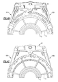
- the #4 bearing 66 and the #5 bearing 68 are supported within a mid-turbine frame (MTF) 70 to straddle radially extending structural struts 72 which are preloaded in tension ( Figures 1C-1D ).
- the MTF 70 provides aft structural support within the thrust case 52C for the #4 bearing 66 and the #5 bearing 68 which rotatably support the spools 14, 24.
- a dual rotor engine such as that disclosed in the illustrated embodiment typically includes a forward frame and a rear frame that support the main rotor bearings.
- the intermediate case (IMC) 48 also includes the radially extending struts 40 which are generally radially aligned with the #2 LPC bearing 62 ( Figure 1B ). It should be understood that various engines with various case and frame structures will benefit from the present invention.
- the turbofan gas turbine engine 10 is mounted to aircraft structure such as an aircraft wing through a mount system 80 attachable by the pylon 12.
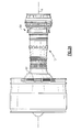
- the mount system 80 includes a forward mount 82 and an aft mount 84 ( Figure 2A ).
- the forward mount 82 is secured to the IMC 48 and the aft mount 84 is secured to the MTF 70 at the thrust case 52C.
- the forward mount 82 and the aft mount 84 are arranged in a plane containing the axis A of the turbofan gas turbine 10. This eliminates the thrust links from the intermediate case, which frees up valuable space beneath the core nacelle and minimizes IMC 48 distortion.
- the mount system 80 reacts the engine thrust at the aft end of the engine 10.
- the term "reacts" as utilized in this disclosure is defined as absorbing a load and dissipating the load to another location of the gas turbine engine 10.
- the forward mount 82 supports vertical loads and side loads.
- the forward mount 82 in one non-limiting embodiment includes a shackle arrangement which mounts to the IMC 48 at two points 86A, 86B.
- the forward mount 82 is generally a plate-like member which is oriented transverse to the plane which contains engine axis A. Fasteners are oriented through the forward mount 82 to engage the intermediate case (IMC) 48 generally parallel to the engine axis A.
- the forward mount 82 is secured to the IMC 48.
- the forward mount 82 is secured to a portion of the core engine, such as the high-pressure compressor case 50 of the gas turbine engine 10 (see Figure 3 ).
- the core engine such as the high-pressure compressor case 50 of the gas turbine engine 10 (see Figure 3 ).
- the aft mount 84 generally includes a first A-arm 88A, a second A-arm 88B, a rear mount platform 90, a wiffle tree assembly 92 and a drag link 94.
- the rear mount platform 90 is attached directly to aircraft structure such as the pylon 12.
- the first A-arm 88A and the second A-arm 88B mount between the thrust case 52C at case bosses 96 which interact with the MTF 70 ( Figures 4B-4C ), the rear mount platform 90 and the wiffle tree assembly 92.
- the first A-arm 88A and the second A-arm 88B may alternatively mount to other areas of the engine 10 such as the high pressure turbine case or other cases.
- other frame arrangements may alternatively be used with any engine case arrangement.
- the first A-arm 88A and the second A-arm 88B are rigid generally triangular arrangements, each having a first link arm 89a, a second link arm 89b and a third link arm 89c.
- the first link arm 89a is between the case boss 96 and the rear mount platform 90.
- the second link arm 89b is between the case bosses 96 and the wiffle tree assembly 92.
- the third link arm 89c is between the wiffle tree assembly 92 rear mount platform 90.
- the first A-arm 88A and the second A-arm 88B primarily support the vertical weight load of the engine 10 and transmit thrust loads from the engine to the rear mount platform 90.
- the first A-arm 88A and the second A-arm 88B of the aft mount 84 force the resultant thrust vector at the engine casing to be reacted along the engine axis A which minimizes tip clearance losses due to engine loading at the aft mount 84. This minimizes blade tip clearance requirements and thereby improves engine performance.
- the wiffle tree assembly 92 includes a wiffle link 98 which supports a central ball joint 100, a first sliding ball joint 102A and a second sliding ball joint 102B ( Figure 4E ). It should be understood that various bushings, vibration isolators and such like may additionally be utilized herewith.
- the central ball joint 100 is attached directly to aircraft structure such as the pylon 12.
- the first sliding ball joint 102A is attached to the first A-arm 88A and the second sliding ball joint 102B is mounted to the first A-arm 88A.
- the first and second sliding ball joint 102A, 102B permit sliding movement of the first and second A-arm 88A, 88B (illustrated by arrow S in Figures 5A and 5B ) to assure that only a vertical load is reacted by the wiffle tree assembly 92. That is, the wiffle tree assembly 92 allows all engine thrust loads to be equalized transmitted to the engine pylon 12 through the rear mount platform 90 by the sliding movement and equalize the thrust load that results from the dual thrust link configuration.
- the wiffle link 98 operates as an equalizing link for vertical loads due to the first sliding ball joint 102A and the second sliding ball joint 102B. As the wiffle link 98 rotates about the central ball joint 100 thrust forces are equalized in the axial direction.
- the wiffle tree assembly 92 experiences loading only due to vertical loads, and is thus less susceptible to failure than conventional thrust-loaded designs.
- the drag link 94 includes a ball joint 104A mounted to the thrust case 52C and ball joint 104B mounted to the rear mount platform 90 ( Figures 4B-4C ).
- the drag link 94 operates to react torque.
- the aft mount 84 transmits engine loads directly to the thrust case 52C and the MTF 70. Thrust, vertical, side, and torque loads are transmitted directly from the MTF 70 which reduces the number of structural members as compared to current in-practice designs.
- the mount system 80 is compact, and occupies space within the core nacelle volume as compared to turbine exhaust case-mounted configurations, which occupy space outside of the core nacelle which may require additional or relatively larger aerodynamic fairings and increase aerodynamic drag and fuel consumption.
- the mount system 80 eliminates the heretofore required thrust links from the IMC, which frees up valuable space adjacent the IMC 48 and the high pressure compressor case 50 within the core nacelle C.
Abstract
Description
- The present invention relates to a gas turbine engine.
- A gas turbine engine may be mounted at various points on an aircraft such as a pylon integrated with an aircraft structure. An engine mounting configuration ensures the transmission of loads between the engine and the aircraft structure. The loads typically include the weight of the engine, thrust, aerodynamic side loads, and rotary torque about the engine axis. The engine mount configuration must also absorb the deformations to which the engine is subjected during different flight phases and the dimensional variations due to thermal expansion and retraction.
- One conventional engine mounting configuration includes a pylon having a forward mount and an aft mount with relatively long thrust links which extend forward from the aft mount to the engine intermediate case structure. Although effective, one disadvantage of this conventional type mounting arrangement is the relatively large "punch loads" into the engine cases from the thrust links which react the thrust from the engine and couple the thrust to the pylon. These loads tend to distort the intermediate case and the low pressure compressor (LPC) cases. The distortion may cause the clearances between the static cases and rotating blade tips to increase which may negatively affect engine performance and increase fuel bum.
- A gas turbine engine according to an exemplary aspect of the present disclosure comprises a fan section, a low spool that includes a low pressure compressor section, the low pressure compressor section includes between four to eight (4-8) stages, a high spool that includes a high pressure compressor section, the high pressure compressor section includes between eight to fifteen (8-15) stages, an overall compressor pressure ratio provided by the combination of the low pressure compressor section and the high pressure compressor, a gear train defined along an engine centerline axis, the low spool operable to drive the fan section through said gear train.
- In a further non-limiting embodiment of any of the foregoing gas turbine engine embodiments, the overall compressor pressure ratio may be above or equal to about fifty (50).
- In a further non-limiting embodiment of any of the foregoing gas turbine engine embodiments, the low pressure compressor may include four (4) stages.
- In a further non-limiting embodiment of any of the foregoing gas turbine engine embodiments, the high pressure compressor may include eight (8) stages.
- In a further non-limiting embodiment of any of the foregoing gas turbine engine embodiments, the low spool may include a three-stage low pressure turbine. Alternatively or additionally, the low pressure turbine may define a low pressure turbine pressure ratio that is greater than about five (5). Alternatively, or additionally, the low pressure turbine may define a low pressure turbine pressure ratio that is greater than five (5).
- In a further non-limiting embodiment of any of the foregoing gas turbine engine embodiments, the gear train may define a gear reduction ratio of greater than or equal to about 2.3.
- In a further non-limiting embodiment of any of the foregoing gas turbine engine embodiments, the gear train may define a gear reduction ratio of greater than or equal to about 2.3.
- In a further non-limiting embodiment of any of the foregoing gas turbine engine embodiments, the gear train may define a gear reduction ratio of greater than or equal to about 2.5.
- In a further non-limiting embodiment of any of the foregoing gas turbine engine embodiments, the gear train may define a gear reduction ratio of greater than or equal to 2.5.
- In a further non-limiting embodiment of any of the foregoing gas turbine engine embodiments, the engine may comprise a fan variable area nozzle to vary a fan nozzle exit area and adjust a pressure ratio of a fan bypass airflow of the fan section during engine operation.
- In a further non-limiting embodiment of any of the foregoing gas turbine engine embodiments, the fan bypass airflow may define a bypass ratio greater than about ten (10).
- In a further non-limiting embodiment of any of the foregoing gas turbine engine embodiments, the fan bypass airflow may define a bypass ratio greater than ten (10).
- In a further non-limiting embodiment of any of the foregoing gas turbine engine embodiments, the engine may comprise a controller operable to control the fan variable area nozzle to vary a fan nozzle exit area and adjust the pressure ratio of the fan bypass airflow to reduce a fan instability.
- A gas turbine engine according to another exemplary aspect of the present disclosure comprises a gear train defined along an engine centerline axis, the gear train defines a gear reduction ratio of greater than or equal to about 2.3 and a spool along the engine centerline axis which drives the gear train, the spool includes a three-stage low pressure turbine and a four to eight (4-8) stage low pressure compressor.
- In a further non-limiting embodiment of any of the foregoing gas turbine engine embodiments, the low pressure turbine may define a low pressure turbine pressure ratio that is greater than five (5).
- In a further non-limiting embodiment of any of the foregoing gas turbine engine embodiments, the gear train may drive a fan section to generate a fan bypass airflow having a bypass ratio greater than ten (10).
- In a further non-limiting embodiment of any of the foregoing gas turbine engine embodiments, the gear train may define a gear reduction ratio of greater than or equal to 2.5.
- In a further non-limiting embodiment of any of the foregoing gas turbine engine embodiments, the low pressure turbine may define a low pressure turbine pressure ratio that is greater than five (5), the gear train defines a gear reduction ratio of greater than or equal to 2.5 to drive a fan section and generate a fan bypass airflow having a bypass ratio greater than ten (10).
- The various features and advantages of this invention will become apparent to those skilled in the art from the following detailed description of the currently disclosed embodiment. The drawings that accompany the detailed description can be briefly described as follows:
-
Figure 1A is a general schematic sectional view through a gas turbine engine along the engine longitudinal axis; -
Figure 1B is a general sectional view through a gas turbine engine along the engine longitudinal axis illustrating an engine static structure case arrangement on the lower half thereof; -
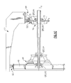
Figure 1C is a side view of an mount system illustrating a rear mount attached through an engine thrust case to a mid-turbine frame between a first and second bearing supported thereby; -
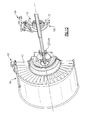
Figure 1D is a forward perspective view of an mount system illustrating a rear mount attached through an engine thrust case to a mid-turbine frame between a first and second bearing supported thereby; -
Figure 2A is a top view of an engine mount system; -
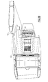
Figure 2B is a side view of an engine mount system within a nacelle system; -
Figure 2C is a forward perspective view of an engine mount system within a nacelle system; -
Figure 3 is a side view of an engine mount system within another front mount; -
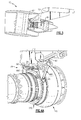
Figure 4A is an aft perspective view of an aft mount; -
Figure 4B is an aft view of an aft mount ofFigure 4A ; -
Figure 4C is a front view of the aft mount ofFigure 4A ; -
Figure 4D is a side view of the aft mount ofFigure 4A ; -
Figure 4E is a top view of the aft mount ofFigure 4A ; -
Figure 5A is a side view of the aft mount ofFigure 4A in a first slide position; and -
Figure 5B is a side view of the aft mount ofFigure 4A in a second slide position. -
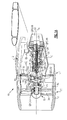
Figure 1A illustrates a general partial fragmentary schematic view of agas turbofan engine 10 suspended from anengine pylon 12 within an engine nacelle assembly N as is typical of an aircraft designed for subsonic operation. - The
turbofan engine 10 includes a core engine within a core nacelle C that houses a low spool 14 andhigh spool 24. The low spool 14 includes alow pressure compressor 16 andlow pressure turbine 18. The low spool 14 drives afan section 20 connected to the low spool 14 either directly or through agear train 25. - The
high spool 24 includes ahigh pressure compressor 26 andhigh pressure turbine 28. Acombustor 30 is arranged between thehigh pressure compressor 26 andhigh pressure turbine 28. The low andhigh spools 14, 24 rotate about an engine axis of rotation A. - In one disclosed, non-limiting embodiment, the
low pressure compressor 16 includes between four to eight (4-8) stages (4stages 16A-16D shown inFigure 1A ), thehigh pressure compressor 26 includes between eight to fifteen (8-15) stages (eight (8)stages 26A-26H shown inFigure 1B ) and thelow pressure turbine 18 includes between three to six (3-6) stages (three (3)stages 18A-18C shown inFigure 1B ). Stated another way, the combination oflow pressure compressor 16 andhigh pressure compressor 26 together provides an overall pressure ratio. In most embodiments, the overall pressure ratio is above or equal to about 50, although it may be below that pressure ratio in some combinations. - The
engine 10 in one non-limiting embodiment is a high-bypass geared architecture aircraft engine. In one disclosed, non-limiting embodiment, theengine 10 bypass ratio is greater than about six (6) to ten (10), thegear train 25 is an epicyclic gear train such as a planetary gear system or other gear system with a gear reduction ratio of greater than about 2.3 and thelow pressure turbine 18 has a pressure ratio that is greater than about 5. In one disclosed embodiment, theengine 10 bypass ratio is greater than about ten (10:1), the turbofan diameter is significantly larger than that of thelow pressure compressor 16, and thelow pressure turbine 18 has a pressure ratio that is greater than about 5:1. Thegear train 25 may be an epicycle gear train such as a planetary gear system or other gear system with a gear reduction ratio of greater than about 2.5:1. It should be understood, however, that the above parameters are only exemplary of one embodiment of a geared architecture engine and that the present invention is applicable to other gas turbine engines including direct drive turbofans. - Airflow enters the fan nacelle F which at least partially surrounds the core nacelle C. The
fan section 20 communicates airflow into the core nacelle C to thelow pressure compressor 16. Core airflow compressed by thelow pressure compressor 16 and thehigh pressure compressor 26 is mixed with the fuel in thecombustor 30 where is ignited, and burned. The resultant high pressure combustor products are expanded through thehigh pressure turbine 28 andlow pressure turbine 18. Theturbines compressors compressors low pressure turbine 18 also drives thefan section 20 throughgear train 25. A core engine exhaust E exits the core nacelle C through acore nozzle 43 defined between the core nacelle C and atail cone 33. - With reference to
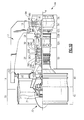
Figure 1B , thelow pressure turbine 18 includes a low number of stages, which, in the illustrated non-limiting embodiment, includes three turbine stages, 18A, 18B, 18C. The gear train 22 operationally effectuates the significantly reduced number of stages within thelow pressure turbine 18. The three turbine stages, 18A, 18B, 18C facilitate a lightweight and operationally efficient engine architecture. It should be appreciated that a low number of turbine stages contemplates, for example, three to six (3-6) stages.Low pressure turbine 18 pressure ratio is pressure measured prior to inlet oflow pressure turbine 18 as related to the pressure at the outlet of thelow pressure turbine 18 prior to exhaust nozzle. - Thrust is a function of density, velocity, and area. One or more of these parameters can be manipulated to vary the amount and direction of thrust provided by the bypass flow B. The Variable Area Fan Nozzle ("VAFN") 42 operates to effectively vary the area of the fan
nozzle exit area 44 to selectively adjust the pressure ratio of the bypass flow B in response to a controller C. Low pressure ratio turbofans are desirable for their high propulsive efficiency. However, low pressure ratio fans may be inherently susceptible to fan stability/flutter problems at low power and low flight speeds. The VAFN 42 allows the engine to change to a more favorable fan operating line at low power, avoiding the instability region, and still provide the relatively smaller nozzle area necessary to obtain a high-efficiency fan operating line at cruise. - A significant amount of thrust is provided by the bypass flow B due to the high bypass ratio. The
fan section 20 of theengine 10 is designed for a particular flight condition -- typically cruise at about 0.8 Mach and about 35,000 feet (10,668 metres). The flight condition of 0.8 Mach and 35,000 ft, with the engine at its best fuel consumption - also known as "bucket cruise Thrust Specific Fuel Consumption ('TSFC')" - is the industry standard parameter of 1bm of fuel being burned divided by lbf of thrust the engine produces at that minimum point. "Low fan pressure ratio" is the pressure ratio across the fan blade alone, without the Fan Exit Guide Vane ("FEGV") system 36. The low fan pressure ratio as disclosed herein according to one non-limiting embodiment is less than about 1.45. "Low corrected fan tip speed" is the actual fan tip speed in ft/sec (1 ft = 0.305 m) divided by an industry standard temperature correction of [(Tambient deg R) / 518.7)^0.5]. The "Low corrected fan tip speed" as disclosed herein according to one non-limiting embodiment is less than about 1150 ft (350 m) / second. - As the fan blades within the
fan section 20 are efficiently designed at a particular fixed stagger angle for an efficient cruise condition, the VAFN 42 is operated to effectively vary the fan nozzle exit area to adjust fan bypass air flow such that the angle of attack or incidence on the fan blades is maintained close to the design incidence for efficient engine operation at other flight conditions, such as landing and takeoff to thus provide optimized engine operation over a range of flight conditions with respect to performance and other operational parameters such as noise levels. - The engine
static structure 44 generally has sub-structures including a case structure often referred to as the engine backbone. The enginestatic structure 44 generally includes afan case 46, an intermediate case (IMC) 48, a highpressure compressor case 50, acombustor case 52A, a highpressure turbine case 52B, athrust case 52C, a lowpressure turbine case 54, and a turbine exhaust case 56 (Figure 1B ). Alternatively, thecombustor case 52A, the highpressure turbine case 52B and thethrust case 52C may be combined into a single case. It should be understood that this is an exemplary configuration and any number of cases may be utilized. - The
fan section 20 includes afan rotor 32 with a plurality of circumferentially spaced radially outwardly extendingfan blades 34. Thefan blades 34 are surrounded by thefan case 46. The core engine case structure is secured to thefan case 46 at theIMC 48 which includes a multiple of circumferentially spaced radially extendingstruts 40 which radially span the core engine case structure and thefan case 20. - The engine
static structure 44 further supports a bearing system upon which theturbines compressors fan rotor 32 rotate. A #1 fandual bearing 60 which rotationally supports thefan rotor 32 is axially located generally within thefan case 46. The #1 fandual bearing 60 is preloaded to react fan thrust forward and aft (in case of surge). A #2 LPC bearing 62 which rotationally supports the low spool 14 is axially located generally within the intermediate case (IMC) 48. The #2LPC bearing 62 reacts thrust. A #3 fandual bearing 64 which rotationally supports thehigh spool 24 and also reacts thrust. The #3 fan bearing 64 is also axially located generally within theIMC 48 just forward of the highpressure compressor case 50. A #4bearing 66 which rotationally supports a rear segment of the low spool 14 reacts only radial loads. The #4bearing 66 is axially located generally within thethrust case 52C in an aft section thereof. A #5bearing 68 rotationally supports the rear segment of the low spool 14 and reacts only radial loads. The #5bearing 68 is axially located generally within thethrust case 52C just aft of the #4bearing 66. It should be understood that this is an exemplary configuration and any number of bearings may be utilized. - The #4
bearing 66 and the #5bearing 68 are supported within a mid-turbine frame (MTF) 70 to straddle radially extendingstructural struts 72 which are preloaded in tension (Figures 1C-1D ). TheMTF 70 provides aft structural support within thethrust case 52C for the #4bearing 66 and the #5bearing 68 which rotatably support thespools 14, 24. - A dual rotor engine such as that disclosed in the illustrated embodiment typically includes a forward frame and a rear frame that support the main rotor bearings. The intermediate case (IMC) 48 also includes the
radially extending struts 40 which are generally radially aligned with the #2 LPC bearing 62 (Figure 1B ). It should be understood that various engines with various case and frame structures will benefit from the present invention. - The turbofan
gas turbine engine 10 is mounted to aircraft structure such as an aircraft wing through a mount system 80 attachable by thepylon 12. The mount system 80 includes aforward mount 82 and an aft mount 84 (Figure 2A ). Theforward mount 82 is secured to theIMC 48 and theaft mount 84 is secured to theMTF 70 at thethrust case 52C. Theforward mount 82 and theaft mount 84 are arranged in a plane containing the axis A of theturbofan gas turbine 10. This eliminates the thrust links from the intermediate case, which frees up valuable space beneath the core nacelle and minimizesIMC 48 distortion. - Referring to
Figures 2A-2C , the mount system 80 reacts the engine thrust at the aft end of theengine 10. The term "reacts" as utilized in this disclosure is defined as absorbing a load and dissipating the load to another location of thegas turbine engine 10. - The
forward mount 82 supports vertical loads and side loads. Theforward mount 82 in one non-limiting embodiment includes a shackle arrangement which mounts to theIMC 48 at two points 86A, 86B. Theforward mount 82 is generally a plate-like member which is oriented transverse to the plane which contains engine axis A. Fasteners are oriented through theforward mount 82 to engage the intermediate case (IMC) 48 generally parallel to the engine axis A. In this illustrated non-limiting embodiment, theforward mount 82 is secured to theIMC 48. In another non-limiting embodiment, theforward mount 82 is secured to a portion of the core engine, such as the high-pressure compressor case 50 of the gas turbine engine 10 (seeFigure 3 ). One of ordinary skill in the art having the benefit of this disclosure would be able to select an appropriate mounting location for theforward mount 82. - Referring to
Figure 4A , theaft mount 84 generally includes afirst A-arm 88A, asecond A-arm 88B, arear mount platform 90, awiffle tree assembly 92 and adrag link 94. Therear mount platform 90 is attached directly to aircraft structure such as thepylon 12. Thefirst A-arm 88A and thesecond A-arm 88B mount between thethrust case 52C atcase bosses 96 which interact with the MTF 70 (Figures 4B-4C ), therear mount platform 90 and thewiffle tree assembly 92. It should be understood that thefirst A-arm 88A and thesecond A-arm 88B may alternatively mount to other areas of theengine 10 such as the high pressure turbine case or other cases. It should also be understood that other frame arrangements may alternatively be used with any engine case arrangement. - Referring to
Figure 4D , thefirst A-arm 88A and thesecond A-arm 88B are rigid generally triangular arrangements, each having afirst link arm 89a, asecond link arm 89b and athird link arm 89c. Thefirst link arm 89a is between thecase boss 96 and therear mount platform 90. Thesecond link arm 89b is between thecase bosses 96 and thewiffle tree assembly 92. Thethird link arm 89c is between thewiffle tree assembly 92rear mount platform 90. Thefirst A-arm 88A and thesecond A-arm 88B primarily support the vertical weight load of theengine 10 and transmit thrust loads from the engine to therear mount platform 90. - The
first A-arm 88A and the second A-arm 88B of theaft mount 84 force the resultant thrust vector at the engine casing to be reacted along the engine axis A which minimizes tip clearance losses due to engine loading at theaft mount 84. This minimizes blade tip clearance requirements and thereby improves engine performance. - The
wiffle tree assembly 92 includes awiffle link 98 which supports a central ball joint 100, a first sliding ball joint 102A and a second sliding ball joint 102B (Figure 4E ). It should be understood that various bushings, vibration isolators and such like may additionally be utilized herewith. The central ball joint 100 is attached directly to aircraft structure such as thepylon 12. The first sliding ball joint 102A is attached to thefirst A-arm 88A and the second sliding ball joint 102B is mounted to thefirst A-arm 88A. The first and second sliding ball joint 102A, 102B permit sliding movement of the first andsecond A-arm Figures 5A and 5B ) to assure that only a vertical load is reacted by thewiffle tree assembly 92. That is, thewiffle tree assembly 92 allows all engine thrust loads to be equalized transmitted to theengine pylon 12 through therear mount platform 90 by the sliding movement and equalize the thrust load that results from the dual thrust link configuration. The wiffle link 98 operates as an equalizing link for vertical loads due to the first sliding ball joint 102A and the second sliding ball joint 102B. As the wiffle link 98 rotates about the central ball joint 100 thrust forces are equalized in the axial direction. Thewiffle tree assembly 92 experiences loading only due to vertical loads, and is thus less susceptible to failure than conventional thrust-loaded designs. - The
drag link 94 includes a ball joint 104A mounted to thethrust case 52C and ball joint 104B mounted to the rear mount platform 90 (Figures 4B-4C ). Thedrag link 94 operates to react torque. - The aft mount 84 transmits engine loads directly to the
thrust case 52C and theMTF 70. Thrust, vertical, side, and torque loads are transmitted directly from theMTF 70 which reduces the number of structural members as compared to current in-practice designs. - The mount system 80 is compact, and occupies space within the core nacelle volume as compared to turbine exhaust case-mounted configurations, which occupy space outside of the core nacelle which may require additional or relatively larger aerodynamic fairings and increase aerodynamic drag and fuel consumption. The mount system 80 eliminates the heretofore required thrust links from the IMC, which frees up valuable space adjacent the
IMC 48 and the highpressure compressor case 50 within the core nacelle C. - It should be understood that relative positional terms such as "forward," "aft," "upper," "lower," "above," "below," and the like are with reference to the normal operational attitude of the vehicle and should not be considered otherwise limiting.
- The foregoing description is exemplary rather than defined by the limitations within. Many modifications and variations of the present invention are possible in light of the above teachings. The disclosed embodiments of this invention have been disclosed, however, one of ordinary skill in the art would recognize that certain modifications would come within the scope of this invention. It is, therefore, to be understood that within the scope of the appended claims, the invention may be practiced otherwise than as specifically described. For that reason the following claims should be studied to determine the true scope and content of this invention.
Claims (15)
- A gas turbine engine (10) comprising:a fan section (20);a low spool (14) that includes a low pressure compressor section (16), said low pressure compressor section (16) includes between four to eight (4-8) stages;a high spool (24) that includes a high pressure compressor section (26), wherein said high pressure compressor section (26) includes between eight to fifteen (8-15) stages; anda gear train (25) defined along an engine centerline axis (A), said low spool (14) operable to drive said fan section (20) through said gear train (25).
- The engine (10) as recited in claim 1, wherein an overall compressor pressure ratio is provided by the combination of said low pressure compressor section (16) and said high pressure compressor (26) and said overall compressor pressure ratio is above or equal to about fifty (50).
- The engine (10) as recited in claim 1 or 2, wherein said low pressure compressor includes four (4) stages.
- The engine (10) as recited in any of claims 1 to 3, wherein said high pressure compressor includes eight (8) stages.
- The engine (10) as recited in any preceding claim, wherein said low spool (14) includes a three-stage low pressure turbine (18).
- The engine (10) as recited in claim 5, wherein said low pressure turbine (18) defines a low pressure turbine pressure ratio that is greater than about five (5), or greater than five (5).
- The engine (10) as recited in any preceding claim, wherein said gear train (25) defines a gear reduction ratio of greater than or equal to about 2.3, or greater than or equal to 2.3.
- The engine (10) as recited in any of claims 1 to 6, wherein said gear train (25) defines a gear reduction ratio of greater than or equal to about 2.5 or greater than or equal to 2.5.
- The engine (10) as set forth in any preceding claim, further comprising a fan variable area nozzle to vary a fan nozzle exit area and adjust a pressure ratio of a fan bypass airflow of said fan section (20) during engine operation.
- The engine (10) as recited in claim 9, wherein said fan bypass airflow defines a bypass ratio greater than about ten (10), or greater than ten (10).
- The engine (10) as recited in claim 9 or 10, further comprising a controller operable to control said fan variable area nozzle to vary a fan nozzle exit area and adjust the pressure ratio of the fan bypass airflow to reduce a fan instability.
- A gas turbine engine (10) comprising:a gear train (25) defined along an engine centerline axis (A), wherein said gear train (25) defines a gear reduction ratio of greater than or equal to about 2.3; anda spool (14) along said engine centerline axis (A) which drives said gear train (25), wherein said spool (14) includes a three-stage low pressure turbine (18) and a four to eight (4-8) stage low pressure compressor (16).
- The engine (10) as recited in claim 12, wherein said low pressure turbine (18) defines a low pressure turbine pressure ratio that is greater than five (5).
- The engine (10) as recited in claim 12 or 13, wherein said gear train (25) drives a fan section (20) to generate a fan bypass airflow having a bypass ratio greater than ten (10).
- The engine (10) as recited in any of claims 12 to 14, wherein said gear train (25) defines a gear reduction ratio of greater than or equal to 2.5.
Priority Applications (1)
| Application Number | Priority Date | Filing Date | Title |
|---|---|---|---|
| EP15171345.0A EP2944790A1 (en) | 2011-12-30 | 2012-12-07 | Gas turbine engine compressor arrangement |
Applications Claiming Priority (1)
| Application Number | Priority Date | Filing Date | Title |
|---|---|---|---|
| US13/340,969 US8807477B2 (en) | 2008-06-02 | 2011-12-30 | Gas turbine engine compressor arrangement |
Related Child Applications (2)
| Application Number | Title | Priority Date | Filing Date |
|---|---|---|---|
| EP15171345.0A Division-Into EP2944790A1 (en) | 2011-12-30 | 2012-12-07 | Gas turbine engine compressor arrangement |
| EP15171345.0A Division EP2944790A1 (en) | 2011-12-30 | 2012-12-07 | Gas turbine engine compressor arrangement |
Publications (3)
| Publication Number | Publication Date |
|---|---|
| EP2610460A2 true EP2610460A2 (en) | 2013-07-03 |
| EP2610460A3 EP2610460A3 (en) | 2014-08-06 |
| EP2610460B1 EP2610460B1 (en) | 2015-07-29 |
Family
ID=47323981
Family Applications (2)
| Application Number | Title | Priority Date | Filing Date |
|---|---|---|---|
| EP12196028.0A Revoked EP2610460B1 (en) | 2011-12-30 | 2012-12-07 | Gas turbine engine |
| EP15171345.0A Withdrawn EP2944790A1 (en) | 2011-12-30 | 2012-12-07 | Gas turbine engine compressor arrangement |
Family Applications After (1)
| Application Number | Title | Priority Date | Filing Date |
|---|---|---|---|
| EP15171345.0A Withdrawn EP2944790A1 (en) | 2011-12-30 | 2012-12-07 | Gas turbine engine compressor arrangement |
Country Status (4)
| Country | Link |
|---|---|
| EP (2) | EP2610460B1 (en) |
| JP (1) | JP2013139782A (en) |
| BR (1) | BR102012028940A2 (en) |
| CA (1) | CA2800001C (en) |
Cited By (10)
| Publication number | Priority date | Publication date | Assignee | Title |
|---|---|---|---|---|
| WO2015006438A1 (en) * | 2013-07-09 | 2015-01-15 | United Technologies Corporation | Plated polymer compressor |
| WO2015047449A1 (en) | 2013-09-30 | 2015-04-02 | United Technologies Corporation | Compressor area splits for geared turbofan |
| CN106965941A (en) * | 2017-05-05 | 2017-07-21 | 唐山海庞科技有限公司 | The universal deflection rudder vector tracker action of aero-engine |
| US20180230912A1 (en) * | 2007-09-21 | 2018-08-16 | United Technologies Corporation | Gas turbine engine compressor arrangement |
| EP2955337B1 (en) | 2014-06-13 | 2020-09-09 | United Technologies Corporation | Geared turbofan architecture |
| US11268526B2 (en) | 2013-07-09 | 2022-03-08 | Raytheon Technologies Corporation | Plated polymer fan |
| US11267576B2 (en) | 2013-07-09 | 2022-03-08 | Raytheon Technologies Corporation | Plated polymer nosecone |
| US11691388B2 (en) | 2013-07-09 | 2023-07-04 | Raytheon Technologies Corporation | Metal-encapsulated polymeric article |
| US11781506B2 (en) | 2020-06-03 | 2023-10-10 | Rtx Corporation | Splitter and guide vane arrangement for gas turbine engines |
| US11846238B2 (en) | 2007-09-21 | 2023-12-19 | Rtx Corporation | Gas turbine engine compressor arrangement |
Families Citing this family (3)
| Publication number | Priority date | Publication date | Assignee | Title |
|---|---|---|---|---|
| CA2936576C (en) * | 2015-08-12 | 2018-05-01 | United Technologies Corporation | Epicyclic gear train |
| US11754000B2 (en) | 2021-07-19 | 2023-09-12 | Rtx Corporation | High and low spool configuration for a gas turbine engine |
| US20230026997A1 (en) * | 2021-07-19 | 2023-01-26 | Raytheon Technologies Corporation | Gas turbine engine compressor arrangement |
Family Cites Families (6)
| Publication number | Priority date | Publication date | Assignee | Title |
|---|---|---|---|---|
| EP2064434B1 (en) * | 2006-10-12 | 2012-06-27 | United Technologies Corporation | Operational line management of low pressure compressor in a turbofan engine |
| US7721549B2 (en) * | 2007-02-08 | 2010-05-25 | United Technologies Corporation | Fan variable area nozzle for a gas turbine engine fan nacelle with cam drive ring actuation system |
| US7942079B2 (en) * | 2007-02-16 | 2011-05-17 | Hamilton Sundstrand Corporation | Multi-speed gearbox for low spool driven auxiliary component |
| US7950237B2 (en) * | 2007-06-25 | 2011-05-31 | United Technologies Corporation | Managing spool bearing load using variable area flow nozzle |
| US8074440B2 (en) * | 2007-08-23 | 2011-12-13 | United Technologies Corporation | Gas turbine engine with axial movable fan variable area nozzle |
| US8128021B2 (en) * | 2008-06-02 | 2012-03-06 | United Technologies Corporation | Engine mount system for a turbofan gas turbine engine |
-
2012
- 2012-11-12 BR BR102012028940A patent/BR102012028940A2/en not_active Application Discontinuation
- 2012-12-07 EP EP12196028.0A patent/EP2610460B1/en not_active Revoked
- 2012-12-07 EP EP15171345.0A patent/EP2944790A1/en not_active Withdrawn
- 2012-12-21 JP JP2012278774A patent/JP2013139782A/en active Pending
- 2012-12-21 CA CA2800001A patent/CA2800001C/en active Active
Non-Patent Citations (1)
| Title |
|---|
| None |
Cited By (15)
| Publication number | Priority date | Publication date | Assignee | Title |
|---|---|---|---|---|
| US11846238B2 (en) | 2007-09-21 | 2023-12-19 | Rtx Corporation | Gas turbine engine compressor arrangement |
| US20180230912A1 (en) * | 2007-09-21 | 2018-08-16 | United Technologies Corporation | Gas turbine engine compressor arrangement |
| US10927843B2 (en) | 2013-07-09 | 2021-02-23 | Raytheon Technologies Corporation | Plated polymer compressor |
| US11691388B2 (en) | 2013-07-09 | 2023-07-04 | Raytheon Technologies Corporation | Metal-encapsulated polymeric article |
| WO2015006438A1 (en) * | 2013-07-09 | 2015-01-15 | United Technologies Corporation | Plated polymer compressor |
| US11267576B2 (en) | 2013-07-09 | 2022-03-08 | Raytheon Technologies Corporation | Plated polymer nosecone |
| US11268526B2 (en) | 2013-07-09 | 2022-03-08 | Raytheon Technologies Corporation | Plated polymer fan |
| EP3052812A4 (en) * | 2013-09-30 | 2016-10-05 | United Technologies Corp | Compressor area splits for geared turbofan |
| US20160215730A1 (en) * | 2013-09-30 | 2016-07-28 | United Technologies Corporation | Compressor area splits for geared turbofan |
| WO2015047449A1 (en) | 2013-09-30 | 2015-04-02 | United Technologies Corporation | Compressor area splits for geared turbofan |
| EP2955337B1 (en) | 2014-06-13 | 2020-09-09 | United Technologies Corporation | Geared turbofan architecture |
| US11448123B2 (en) | 2014-06-13 | 2022-09-20 | Raytheon Technologies Corporation | Geared turbofan architecture |
| CN106965941B (en) * | 2017-05-05 | 2019-11-05 | 唐山海庞科技有限公司 | The universal deflection rudder vector tracker action of aero-engine |
| CN106965941A (en) * | 2017-05-05 | 2017-07-21 | 唐山海庞科技有限公司 | The universal deflection rudder vector tracker action of aero-engine |
| US11781506B2 (en) | 2020-06-03 | 2023-10-10 | Rtx Corporation | Splitter and guide vane arrangement for gas turbine engines |
Also Published As
| Publication number | Publication date |
|---|---|
| CA2800001A1 (en) | 2013-06-30 |
| CA2800001C (en) | 2015-10-13 |
| JP2013139782A (en) | 2013-07-18 |
| BR102012028940A2 (en) | 2015-10-06 |
| EP2610460B1 (en) | 2015-07-29 |
| EP2944790A1 (en) | 2015-11-18 |
| EP2610460A3 (en) | 2014-08-06 |
Similar Documents
| Publication | Publication Date | Title |
|---|---|---|
| US11286883B2 (en) | Gas turbine engine with low stage count low pressure turbine and engine mounting arrangement | |
| CA2849013C (en) | Gas turbine engine with low stage count low pressure turbine | |
| US8448895B2 (en) | Gas turbine engine compressor arrangement | |
| US8511604B2 (en) | Gas turbine engine with low stage count low pressure turbine | |
| EP2610460B1 (en) | Gas turbine engine | |
| US8684303B2 (en) | Gas turbine engine compressor arrangement | |
| US8511605B2 (en) | Gas turbine engine with low stage count low pressure turbine | |
| CA2800464C (en) | Gas turbine engine with low stage count low pressure turbine |
Legal Events
| Date | Code | Title | Description |
|---|---|---|---|
| PUAI | Public reference made under article 153(3) epc to a published international application that has entered the european phase |
Free format text: ORIGINAL CODE: 0009012 |
|
| AK | Designated contracting states |
Kind code of ref document: A2 Designated state(s): AL AT BE BG CH CY CZ DE DK EE ES FI FR GB GR HR HU IE IS IT LI LT LU LV MC MK MT NL NO PL PT RO RS SE SI SK SM TR |
|
| AX | Request for extension of the european patent |
Extension state: BA ME |
|
| PUAL | Search report despatched |
Free format text: ORIGINAL CODE: 0009013 |
|
| AK | Designated contracting states |
Kind code of ref document: A3 Designated state(s): AL AT BE BG CH CY CZ DE DK EE ES FI FR GB GR HR HU IE IS IT LI LT LU LV MC MK MT NL NO PL PT RO RS SE SI SK SM TR |
|
| AX | Request for extension of the european patent |
Extension state: BA ME |
|
| RIC1 | Information provided on ipc code assigned before grant |
Ipc: F02C 7/36 20060101ALI20140703BHEP Ipc: F02C 3/06 20060101AFI20140703BHEP Ipc: F02K 3/06 20060101ALI20140703BHEP Ipc: F01D 25/28 20060101ALI20140703BHEP |
|
| 17P | Request for examination filed |
Effective date: 20150205 |
|
| RBV | Designated contracting states (corrected) |
Designated state(s): AL AT BE BG CH CY CZ DE DK EE ES FI FR GB GR HR HU IE IS IT LI LT LU LV MC MK MT NL NO PL PT RO RS SE SI SK SM TR |
|
| GRAP | Despatch of communication of intention to grant a patent |
Free format text: ORIGINAL CODE: EPIDOSNIGR1 |
|
| INTG | Intention to grant announced |
Effective date: 20150515 |
|
| GRAS | Grant fee paid |
Free format text: ORIGINAL CODE: EPIDOSNIGR3 |
|
| GRAA | (expected) grant |
Free format text: ORIGINAL CODE: 0009210 |
|
| STAA | Information on the status of an ep patent application or granted ep patent |
Free format text: STATUS: THE PATENT HAS BEEN GRANTED |
|
| AK | Designated contracting states |
Kind code of ref document: B1 Designated state(s): AL AT BE BG CH CY CZ DE DK EE ES FI FR GB GR HR HU IE IS IT LI LT LU LV MC MK MT NL NO PL PT RO RS SE SI SK SM TR |
|
| REG | Reference to a national code |
Ref country code: GB Ref legal event code: FG4D |
|
| REG | Reference to a national code |
Ref country code: CH Ref legal event code: EP |
|
| REG | Reference to a national code |
Ref country code: AT Ref legal event code: REF Ref document number: 739493 Country of ref document: AT Kind code of ref document: T Effective date: 20150815 |
|
| REG | Reference to a national code |
Ref country code: IE Ref legal event code: FG4D |
|
| REG | Reference to a national code |
Ref country code: DE Ref legal event code: R096 Ref document number: 602012009101 Country of ref document: DE |
|
| REG | Reference to a national code |
Ref country code: AT Ref legal event code: MK05 Ref document number: 739493 Country of ref document: AT Kind code of ref document: T Effective date: 20150729 |
|
| REG | Reference to a national code |
Ref country code: FR Ref legal event code: PLFP Year of fee payment: 4 |
|
| REG | Reference to a national code |
Ref country code: LT Ref legal event code: MG4D |
|
| REG | Reference to a national code |
Ref country code: NL Ref legal event code: MP Effective date: 20150729 |
|
| PG25 | Lapsed in a contracting state [announced via postgrant information from national office to epo] |
Ref country code: LV Free format text: LAPSE BECAUSE OF FAILURE TO SUBMIT A TRANSLATION OF THE DESCRIPTION OR TO PAY THE FEE WITHIN THE PRESCRIBED TIME-LIMIT Effective date: 20150729 Ref country code: NO Free format text: LAPSE BECAUSE OF FAILURE TO SUBMIT A TRANSLATION OF THE DESCRIPTION OR TO PAY THE FEE WITHIN THE PRESCRIBED TIME-LIMIT Effective date: 20151029 Ref country code: GR Free format text: LAPSE BECAUSE OF FAILURE TO SUBMIT A TRANSLATION OF THE DESCRIPTION OR TO PAY THE FEE WITHIN THE PRESCRIBED TIME-LIMIT Effective date: 20151030 Ref country code: FI Free format text: LAPSE BECAUSE OF FAILURE TO SUBMIT A TRANSLATION OF THE DESCRIPTION OR TO PAY THE FEE WITHIN THE PRESCRIBED TIME-LIMIT Effective date: 20150729 Ref country code: LT Free format text: LAPSE BECAUSE OF FAILURE TO SUBMIT A TRANSLATION OF THE DESCRIPTION OR TO PAY THE FEE WITHIN THE PRESCRIBED TIME-LIMIT Effective date: 20150729 |
|
| PG25 | Lapsed in a contracting state [announced via postgrant information from national office to epo] |
Ref country code: PL Free format text: LAPSE BECAUSE OF FAILURE TO SUBMIT A TRANSLATION OF THE DESCRIPTION OR TO PAY THE FEE WITHIN THE PRESCRIBED TIME-LIMIT Effective date: 20150729 Ref country code: IS Free format text: LAPSE BECAUSE OF FAILURE TO SUBMIT A TRANSLATION OF THE DESCRIPTION OR TO PAY THE FEE WITHIN THE PRESCRIBED TIME-LIMIT Effective date: 20151129 Ref country code: AT Free format text: LAPSE BECAUSE OF FAILURE TO SUBMIT A TRANSLATION OF THE DESCRIPTION OR TO PAY THE FEE WITHIN THE PRESCRIBED TIME-LIMIT Effective date: 20150729 Ref country code: ES Free format text: LAPSE BECAUSE OF FAILURE TO SUBMIT A TRANSLATION OF THE DESCRIPTION OR TO PAY THE FEE WITHIN THE PRESCRIBED TIME-LIMIT Effective date: 20150729 Ref country code: SE Free format text: LAPSE BECAUSE OF FAILURE TO SUBMIT A TRANSLATION OF THE DESCRIPTION OR TO PAY THE FEE WITHIN THE PRESCRIBED TIME-LIMIT Effective date: 20150729 Ref country code: HR Free format text: LAPSE BECAUSE OF FAILURE TO SUBMIT A TRANSLATION OF THE DESCRIPTION OR TO PAY THE FEE WITHIN THE PRESCRIBED TIME-LIMIT Effective date: 20150729 Ref country code: PT Free format text: LAPSE BECAUSE OF FAILURE TO SUBMIT A TRANSLATION OF THE DESCRIPTION OR TO PAY THE FEE WITHIN THE PRESCRIBED TIME-LIMIT Effective date: 20151130 Ref country code: RS Free format text: LAPSE BECAUSE OF FAILURE TO SUBMIT A TRANSLATION OF THE DESCRIPTION OR TO PAY THE FEE WITHIN THE PRESCRIBED TIME-LIMIT Effective date: 20150729 |
|
| PG25 | Lapsed in a contracting state [announced via postgrant information from national office to epo] |
Ref country code: NL Free format text: LAPSE BECAUSE OF FAILURE TO SUBMIT A TRANSLATION OF THE DESCRIPTION OR TO PAY THE FEE WITHIN THE PRESCRIBED TIME-LIMIT Effective date: 20150729 |
|
| REG | Reference to a national code |
Ref country code: DE Ref legal event code: R026 Ref document number: 602012009101 Country of ref document: DE |
|
| PG25 | Lapsed in a contracting state [announced via postgrant information from national office to epo] |
Ref country code: EE Free format text: LAPSE BECAUSE OF FAILURE TO SUBMIT A TRANSLATION OF THE DESCRIPTION OR TO PAY THE FEE WITHIN THE PRESCRIBED TIME-LIMIT Effective date: 20150729 Ref country code: SK Free format text: LAPSE BECAUSE OF FAILURE TO SUBMIT A TRANSLATION OF THE DESCRIPTION OR TO PAY THE FEE WITHIN THE PRESCRIBED TIME-LIMIT Effective date: 20150729 Ref country code: DK Free format text: LAPSE BECAUSE OF FAILURE TO SUBMIT A TRANSLATION OF THE DESCRIPTION OR TO PAY THE FEE WITHIN THE PRESCRIBED TIME-LIMIT Effective date: 20150729 Ref country code: IT Free format text: LAPSE BECAUSE OF FAILURE TO SUBMIT A TRANSLATION OF THE DESCRIPTION OR TO PAY THE FEE WITHIN THE PRESCRIBED TIME-LIMIT Effective date: 20150729 Ref country code: CZ Free format text: LAPSE BECAUSE OF FAILURE TO SUBMIT A TRANSLATION OF THE DESCRIPTION OR TO PAY THE FEE WITHIN THE PRESCRIBED TIME-LIMIT Effective date: 20150729 |
|
| PLBI | Opposition filed |
Free format text: ORIGINAL CODE: 0009260 |
|
| PG25 | Lapsed in a contracting state [announced via postgrant information from national office to epo] |
Ref country code: BE Free format text: LAPSE BECAUSE OF NON-PAYMENT OF DUE FEES Effective date: 20151231 Ref country code: RO Free format text: LAPSE BECAUSE OF FAILURE TO SUBMIT A TRANSLATION OF THE DESCRIPTION OR TO PAY THE FEE WITHIN THE PRESCRIBED TIME-LIMIT Effective date: 20150729 |
|
| 26 | Opposition filed |
Opponent name: SNECMA Effective date: 20160427 |
|
| PLAX | Notice of opposition and request to file observation + time limit sent |
Free format text: ORIGINAL CODE: EPIDOSNOBS2 |
|
| PG25 | Lapsed in a contracting state [announced via postgrant information from national office to epo] |
Ref country code: LU Free format text: LAPSE BECAUSE OF FAILURE TO SUBMIT A TRANSLATION OF THE DESCRIPTION OR TO PAY THE FEE WITHIN THE PRESCRIBED TIME-LIMIT Effective date: 20151207 Ref country code: MC Free format text: LAPSE BECAUSE OF FAILURE TO SUBMIT A TRANSLATION OF THE DESCRIPTION OR TO PAY THE FEE WITHIN THE PRESCRIBED TIME-LIMIT Effective date: 20150729 |
|
| REG | Reference to a national code |
Ref country code: CH Ref legal event code: PL |
|
| PG25 | Lapsed in a contracting state [announced via postgrant information from national office to epo] |
Ref country code: SI Free format text: LAPSE BECAUSE OF FAILURE TO SUBMIT A TRANSLATION OF THE DESCRIPTION OR TO PAY THE FEE WITHIN THE PRESCRIBED TIME-LIMIT Effective date: 20150729 |
|
| REG | Reference to a national code |
Ref country code: IE Ref legal event code: MM4A |
|
| PLBB | Reply of patent proprietor to notice(s) of opposition received |
Free format text: ORIGINAL CODE: EPIDOSNOBS3 |
|
| RAP2 | Party data changed (patent owner data changed or rights of a patent transferred) |
Owner name: UNITED TECHNOLOGIES CORPORATION |
|
| PG25 | Lapsed in a contracting state [announced via postgrant information from national office to epo] |
Ref country code: LI Free format text: LAPSE BECAUSE OF NON-PAYMENT OF DUE FEES Effective date: 20151231 Ref country code: CH Free format text: LAPSE BECAUSE OF NON-PAYMENT OF DUE FEES Effective date: 20151231 Ref country code: IE Free format text: LAPSE BECAUSE OF NON-PAYMENT OF DUE FEES Effective date: 20151207 |
|
| PLAB | Opposition data, opponent's data or that of the opponent's representative modified |
Free format text: ORIGINAL CODE: 0009299OPPO |
|
| REG | Reference to a national code |
Ref country code: FR Ref legal event code: PLFP Year of fee payment: 5 |
|
| R26 | Opposition filed (corrected) |
Opponent name: SAFRAN AIRCRAFT ENGINES Effective date: 20160427 |
|
| PG25 | Lapsed in a contracting state [announced via postgrant information from national office to epo] |
Ref country code: BE Free format text: LAPSE BECAUSE OF FAILURE TO SUBMIT A TRANSLATION OF THE DESCRIPTION OR TO PAY THE FEE WITHIN THE PRESCRIBED TIME-LIMIT Effective date: 20150729 |
|
| REG | Reference to a national code |
Ref country code: FR Ref legal event code: CA Effective date: 20170324 |
|
| PG25 | Lapsed in a contracting state [announced via postgrant information from national office to epo] |
Ref country code: BG Free format text: LAPSE BECAUSE OF FAILURE TO SUBMIT A TRANSLATION OF THE DESCRIPTION OR TO PAY THE FEE WITHIN THE PRESCRIBED TIME-LIMIT Effective date: 20150729 Ref country code: SM Free format text: LAPSE BECAUSE OF FAILURE TO SUBMIT A TRANSLATION OF THE DESCRIPTION OR TO PAY THE FEE WITHIN THE PRESCRIBED TIME-LIMIT Effective date: 20150729 Ref country code: HU Free format text: LAPSE BECAUSE OF FAILURE TO SUBMIT A TRANSLATION OF THE DESCRIPTION OR TO PAY THE FEE WITHIN THE PRESCRIBED TIME-LIMIT; INVALID AB INITIO Effective date: 20121207 |
|
| PG25 | Lapsed in a contracting state [announced via postgrant information from national office to epo] |
Ref country code: CY Free format text: LAPSE BECAUSE OF FAILURE TO SUBMIT A TRANSLATION OF THE DESCRIPTION OR TO PAY THE FEE WITHIN THE PRESCRIBED TIME-LIMIT Effective date: 20150729 |
|
| REG | Reference to a national code |
Ref country code: DE Ref legal event code: R082 Ref document number: 602012009101 Country of ref document: DE Representative=s name: SCHMITT-NILSON SCHRAUD WAIBEL WOHLFROM PATENTA, DE |
|
| REG | Reference to a national code |
Ref country code: DE Ref legal event code: R082 Ref document number: 602012009101 Country of ref document: DE Representative=s name: SCHMITT-NILSON SCHRAUD WAIBEL WOHLFROM PATENTA, DE Ref country code: DE Ref legal event code: R081 Ref document number: 602012009101 Country of ref document: DE Owner name: UNITED TECHNOLOGIES CORP. (N.D.GES.D. STAATES , US Free format text: FORMER OWNER: UNITED TECHNOLOGIES CORPORATION, HARTFORD, CONN., US |
|
| PG25 | Lapsed in a contracting state [announced via postgrant information from national office to epo] |
Ref country code: MT Free format text: LAPSE BECAUSE OF FAILURE TO SUBMIT A TRANSLATION OF THE DESCRIPTION OR TO PAY THE FEE WITHIN THE PRESCRIBED TIME-LIMIT Effective date: 20150729 |
|
| REG | Reference to a national code |
Ref country code: FR Ref legal event code: PLFP Year of fee payment: 6 |
|
| APAH | Appeal reference modified |
Free format text: ORIGINAL CODE: EPIDOSCREFNO |
|
| APAW | Appeal reference deleted |
Free format text: ORIGINAL CODE: EPIDOSDREFNO |
|
| APBM | Appeal reference recorded |
Free format text: ORIGINAL CODE: EPIDOSNREFNO |
|
| APBP | Date of receipt of notice of appeal recorded |
Free format text: ORIGINAL CODE: EPIDOSNNOA2O |
|
| APBQ | Date of receipt of statement of grounds of appeal recorded |
Free format text: ORIGINAL CODE: EPIDOSNNOA3O |
|
| APBQ | Date of receipt of statement of grounds of appeal recorded |
Free format text: ORIGINAL CODE: EPIDOSNNOA3O |
|
| PG25 | Lapsed in a contracting state [announced via postgrant information from national office to epo] |
Ref country code: MK Free format text: LAPSE BECAUSE OF FAILURE TO SUBMIT A TRANSLATION OF THE DESCRIPTION OR TO PAY THE FEE WITHIN THE PRESCRIBED TIME-LIMIT Effective date: 20150729 Ref country code: TR Free format text: LAPSE BECAUSE OF FAILURE TO SUBMIT A TRANSLATION OF THE DESCRIPTION OR TO PAY THE FEE WITHIN THE PRESCRIBED TIME-LIMIT Effective date: 20150729 |
|
| PG25 | Lapsed in a contracting state [announced via postgrant information from national office to epo] |
Ref country code: AL Free format text: LAPSE BECAUSE OF FAILURE TO SUBMIT A TRANSLATION OF THE DESCRIPTION OR TO PAY THE FEE WITHIN THE PRESCRIBED TIME-LIMIT Effective date: 20150729 |
|
| PGFP | Annual fee paid to national office [announced via postgrant information from national office to epo] |
Ref country code: GB Payment date: 20201123 Year of fee payment: 9 Ref country code: FR Payment date: 20201120 Year of fee payment: 9 Ref country code: DE Payment date: 20201119 Year of fee payment: 9 |
|
| RAP2 | Party data changed (patent owner data changed or rights of a patent transferred) |
Owner name: RAYTHEON TECHNOLOGIES CORPORATION |
|
| REG | Reference to a national code |
Ref country code: DE Ref legal event code: R064 Ref document number: 602012009101 Country of ref document: DE Ref country code: DE Ref legal event code: R103 Ref document number: 602012009101 Country of ref document: DE |
|
| APBU | Appeal procedure closed |
Free format text: ORIGINAL CODE: EPIDOSNNOA9O |
|
| RDAF | Communication despatched that patent is revoked |
Free format text: ORIGINAL CODE: EPIDOSNREV1 |
|
| RDAG | Patent revoked |
Free format text: ORIGINAL CODE: 0009271 |
|
| STAA | Information on the status of an ep patent application or granted ep patent |
Free format text: STATUS: PATENT REVOKED |
|
| REG | Reference to a national code |
Ref country code: FI Ref legal event code: MGE |
|
| 27W | Patent revoked |
Effective date: 20210412 |
|
| GBPR | Gb: patent revoked under art. 102 of the ep convention designating the uk as contracting state |
Effective date: 20210412 |