EP2610400A1 - Dryer and method to control a drying cycle - Google Patents
Dryer and method to control a drying cycle Download PDFInfo
- Publication number
- EP2610400A1 EP2610400A1 EP11195812.0A EP11195812A EP2610400A1 EP 2610400 A1 EP2610400 A1 EP 2610400A1 EP 11195812 A EP11195812 A EP 11195812A EP 2610400 A1 EP2610400 A1 EP 2610400A1
- Authority
- EP
- European Patent Office
- Prior art keywords
- cycle
- dryer
- drying
- heating elements
- heater
- Prior art date
- Legal status (The legal status is an assumption and is not a legal conclusion. Google has not performed a legal analysis and makes no representation as to the accuracy of the status listed.)
- Granted
Links
Images




Classifications
-
- D—TEXTILES; PAPER
- D06—TREATMENT OF TEXTILES OR THE LIKE; LAUNDERING; FLEXIBLE MATERIALS NOT OTHERWISE PROVIDED FOR
- D06F—LAUNDERING, DRYING, IRONING, PRESSING OR FOLDING TEXTILE ARTICLES
- D06F34/00—Details of control systems for washing machines, washer-dryers or laundry dryers
- D06F34/14—Arrangements for detecting or measuring specific parameters
- D06F34/26—Condition of the drying air, e.g. air humidity or temperature
-
- D—TEXTILES; PAPER
- D06—TREATMENT OF TEXTILES OR THE LIKE; LAUNDERING; FLEXIBLE MATERIALS NOT OTHERWISE PROVIDED FOR
- D06F—LAUNDERING, DRYING, IRONING, PRESSING OR FOLDING TEXTILE ARTICLES
- D06F2101/00—User input for the control of domestic laundry washing machines, washer-dryers or laundry dryers
- D06F2101/20—Operation modes, e.g. delicate laundry washing programs, service modes or refreshment cycles
-
- D—TEXTILES; PAPER
- D06—TREATMENT OF TEXTILES OR THE LIKE; LAUNDERING; FLEXIBLE MATERIALS NOT OTHERWISE PROVIDED FOR
- D06F—LAUNDERING, DRYING, IRONING, PRESSING OR FOLDING TEXTILE ARTICLES
- D06F2103/00—Parameters monitored or detected for the control of domestic laundry washing machines, washer-dryers or laundry dryers
- D06F2103/02—Characteristics of laundry or load
- D06F2103/08—Humidity
-
- D—TEXTILES; PAPER
- D06—TREATMENT OF TEXTILES OR THE LIKE; LAUNDERING; FLEXIBLE MATERIALS NOT OTHERWISE PROVIDED FOR
- D06F—LAUNDERING, DRYING, IRONING, PRESSING OR FOLDING TEXTILE ARTICLES
- D06F2103/00—Parameters monitored or detected for the control of domestic laundry washing machines, washer-dryers or laundry dryers
- D06F2103/28—Air properties
- D06F2103/32—Temperature
-
- D—TEXTILES; PAPER
- D06—TREATMENT OF TEXTILES OR THE LIKE; LAUNDERING; FLEXIBLE MATERIALS NOT OTHERWISE PROVIDED FOR
- D06F—LAUNDERING, DRYING, IRONING, PRESSING OR FOLDING TEXTILE ARTICLES
- D06F2105/00—Systems or parameters controlled or affected by the control systems of washing machines, washer-dryers or laundry dryers
- D06F2105/28—Electric heating
-
- D—TEXTILES; PAPER
- D06—TREATMENT OF TEXTILES OR THE LIKE; LAUNDERING; FLEXIBLE MATERIALS NOT OTHERWISE PROVIDED FOR
- D06F—LAUNDERING, DRYING, IRONING, PRESSING OR FOLDING TEXTILE ARTICLES
- D06F2105/00—Systems or parameters controlled or affected by the control systems of washing machines, washer-dryers or laundry dryers
- D06F2105/50—Starting machine operation, e.g. delayed start or re-start after power cut
-
- D—TEXTILES; PAPER
- D06—TREATMENT OF TEXTILES OR THE LIKE; LAUNDERING; FLEXIBLE MATERIALS NOT OTHERWISE PROVIDED FOR
- D06F—LAUNDERING, DRYING, IRONING, PRESSING OR FOLDING TEXTILE ARTICLES
- D06F2105/00—Systems or parameters controlled or affected by the control systems of washing machines, washer-dryers or laundry dryers
- D06F2105/62—Stopping or disabling machine operation
-
- D—TEXTILES; PAPER
- D06—TREATMENT OF TEXTILES OR THE LIKE; LAUNDERING; FLEXIBLE MATERIALS NOT OTHERWISE PROVIDED FOR
- D06F—LAUNDERING, DRYING, IRONING, PRESSING OR FOLDING TEXTILE ARTICLES
- D06F34/00—Details of control systems for washing machines, washer-dryers or laundry dryers
- D06F34/08—Control circuits or arrangements thereof
-
- D—TEXTILES; PAPER
- D06—TREATMENT OF TEXTILES OR THE LIKE; LAUNDERING; FLEXIBLE MATERIALS NOT OTHERWISE PROVIDED FOR
- D06F—LAUNDERING, DRYING, IRONING, PRESSING OR FOLDING TEXTILE ARTICLES
- D06F58/00—Domestic laundry dryers
- D06F58/32—Control of operations performed in domestic laundry dryers
- D06F58/34—Control of operations performed in domestic laundry dryers characterised by the purpose or target of the control
- D06F58/36—Control of operational steps, e.g. for optimisation or improvement of operational steps depending on the condition of the laundry
- D06F58/38—Control of operational steps, e.g. for optimisation or improvement of operational steps depending on the condition of the laundry of drying, e.g. to achieve the target humidity
Definitions
- the present invention relates to a dryer and a method to control a drying cycle, in particular a "non-cotton" drying cycle, in an efficient manner. More in particular, the dryer and the method of the invention reduce the duration of "non-cotton" cycles and effectively control the working temperature of the same.
- a dryer is an appliance used to remove moisture from a load, such as clothing and other textiles, generally shortly after they are cleaned in a washing machine.
- tumble dryers consist of a rotating drum called a tumbler, thus called tumble dryer, through which heated air is circulated to evaporate the moisture from the load.
- the tumbler is rotated around its axis.
- the temperature of the heated air is generally changeable, depending on the size and nature of the load.
- the user can select a predetermined laundry cycle among a plurality depending on the type of fabric(s) in which the clothes forming the laundry is made.
- a cotton cycle is generally present, also called “normal” or “standard” cycle.
- Cotton fibers, as well as linen ones, are natural fibers that can withstand heat, thus generally the normal cycle is performed at a relatively high temperature in order to quickly dry the clothes. This cycle is used for natural resistant fibers.
- a synthetic cycle may be present, also called permanent press.
- the dryer maintains a warm but not hot temperature in order not to damage synthetic fabrics such as nylon, polyester, acrylic and other synthetic blends, which are easily damaged by high temperature.
- This setting can also work for natural fiber clothes at risk of shrinking.
- a delicate cycle can also be present, in which a cooler temperature than in the synthetic cycle is maintained.
- This delicate setting can be used for example for items labeled as "hand wash,” woolen fabrics that can be machine washed and dried, heat-sensitive garments labeled as "tumble dry low", lingerie and other fragile clothing.
- the heater that heats the air flowing within the dryer includes two heating elements.
- both heating elements heat the air raising its temperature in order to dry the clothes, and to avoid overheating, one of the two heating elements is switched on and off during the cycle.
- only one of the heating elements is heating the air to keep a lower temperature; the only working heating element is then switched on and off depending to the temperature present into the dryer during the cycle to keep a substantially constant, but lower, temperature.
- European patent application EP 0362676 discloses a laundry drying control device for a clothes drier comprising an electrical heating element divided into two portions (5, 6), portion (5) being adapted to be short-circuited by a driver (16) controlled by an electronic comparator (14) or by a logical AND gate (15).
- the device is adapted to control the run of "acrylic" drying cycles by switching on the maximum power of only the portion (6) of the heating element until the operating drying temperature is reached, and then switching on a reduced heating power via the two portions (5, 6) of the heating element.
- the device is adapted to control the run of "extra dry” drying cycles by switching on the maximum heating power and then the reduced heating power for a supplementary period after the end of drying.
- US patent application US 2008/0210769 describes a heating system and a method of controlling the heating system. When a heating unit and a switch are turned on and off repeatedly by the predetermined number of times or more, only some of heaters of the heating unit are turned on, thereby increasing service life of the heating unit and the switch.
- European patent application EP 1076128 is relative to a tumble dryer having an electric heating element 10 switched between first and second states in a regular repetitive cycle.
- the heating element 10 is switched either fully on or fully off by a relay 24 according to a pulse width modulation control by a microprocessor 21.
- the effective heater output is continuously variable to any desired level.
- UK patent application GB 2296793 describes a domestic tumbler drier with a fan which blows air through a heater.
- the drier has temperature and moisture sensors as well as a programmable electronic controller which can store measured values and process variables.
- the air temperature (delta 4s) at the drum exit is measured and during a time interval (t0-t2) part or all of the heater is periodically switched ON and OFF.
- temperature measurements at the heater inlet (delta 2), at the drum inlet (delta 3) and at the drum exit (delta 4) are used to calculate temperature differences which are stored together with the time elapsed.
- Temperatures and laundry moisture contents are measured continuously or with a frequency of several times per second.
- limiting values (A1, A2) according to previously input laundry parameters have been reached
- one of several stored process sequences are fed to the controller.
- the controller uses a fuzzy logic processor to estimate the drying time from the temperature differentials in the start-up period and the time taken to reach a critical outlet temp. or intermediate laundry moisture content.
- the controller has a number of algorithms for various input conditions, e.g. different degrees of required dryness, laundry type, etc.
- the present invention relates to a dryer and a method to control a drying cycle aimed at improving a "non cotton drying cycle".
- the time required to perform a "non cotton" cycle compared with the time required to perform the same cycle by dryers according to the prior art, is reduced. Reducing the drying time of a cycle is desired not only for a practical convenience of the user that has his/her laundry quickly ready, but also for environmental consciousness in order to consume as less energy as possible.
- the method of the invention, and the dryer operating according to said method are relatively simple and do not require expensive modifications to dryers according to the prior art in order to achieve the goals of the invention, therefore the dryer according to the invention is not more costly due to sophisticate components.
- dryers comprise a rotating drum called a tumbler through which heated air is circulated to evaporate the moisture from the load.
- the tumbler is rotated to maintain space between the articles in the load.
- the drum is located inside a tub for the washing cycles.
- Known laundry dryer includes two categories: condense laundry dryers and vented laundry dryers. Dryers of the first category circulate air exhausted from the drum through a heat exchanger/condenser to cool the air and condense the moisture; they subsequently re-circulate the air back through the drum. Dryers of the second category draw air from the surrounding area, heat it, blow it into the drum during operation and then exhaust it through a vent into the outside.
- the present invention is applicable, not only to washer-dryer and dryers, but also to dryers belonging to both of the above mentioned categories.
- a dryer In order to dry the clothes, a dryer includes a fan, preferably a blower, to force air into the drum, and a heater to heat the air that flows through the dryer.
- the dryer of the invention can be operated in various modes, i.e. different types of “drying cycles” can be selected, for example through an input panel or user interface located on the casing of the dryer and accessible to the user.
- a "non cotton” drying cycle is present.
- any cycle in which the drying temperature is set lower than the "cotton cycle” is meant, such as a synthetic fiber drying cycle or a delicate drying cycle.
- the cotton cycle is the cycle used to dry natural fibers such as cotton and/or linen, and the air forced into the drum is at a relatively high temperature.
- the air which is forced into the drum has a lower temperature than the one used during the cotton cycle before defined.
- the dryer in addition includes an air circulation system for the circulation of the air heated by the heater and forced by the fan through the drum to dry the items therein located.
- the heater in turn includes a first heating element and a second heating element, preferably electrical heating elements, such as resistors. It is to be understood that each of the first and second heating element can be further divided in additional "smaller" elements, without changing the teaching of the invention. Moreover, additional heating elements can also be provided in the heater of the invention.
- First and second heating elements are preferably connected electrically and a variable power supply which can switch on and off alternatively one or both of the first and/or second heating element commands the same.
- a controller supervises the operation of the dryer.
- Applicants have considered the teaching of the prior art and operated the above described dryer accordingly.
- having selected a "non-cotton" drying cycle they have used the known teaching according to which only one of the heating elements (either the first or the second) is used to heat air, and the same is switched on and off depending on the temperature reached inside the drum.
- the results achieved using the method of the prior art is shown: during a non-cotton drying cycle, only one of the heating elements is heating the air flowing into the air circulation system (in the graph of fig.
- a first heating element having a power of 900 W is operated, the second heating element being non activated) and in this way the desired working temperature to heat the laundry is reached in approximately 1 hour, as clearly seen from the temperature curves displayed in the graph of fig. 5b (each curve represents a different test).
- the single heating working element is switched off, and switched on again when the temperature lowers below a certain pre-set threshold (see the sudden drop(s) in emitted power in graph of fig. 5a and the corresponding temperature fall(s)in fig. 5b , with the subsequent rise(s) in both curves).
- the invention is relative to a dryer for drying fabric items according to a plurality of drying cycles, said plurality including at least a non-cotton cycle, said dryer comprising:
- the invention relates to a method to control a drying cycle of a dryer, said dryer including
- Applicants have realized that modulating the heating elements during the non-cotton cycle so that they are either both on or both off shortens the cycle duration: the working temperature is reached faster and in addition the time to restore the working temperature is reduced.
- the heater when both heating elements are switched on the heater is at full power, when the heating elements are both switched off, the heater is wholly off.
- variable power supply is apt to switch on again both first and second heating elements when a second threshold temperature has been subsequently reached.
- said controller includes an end of cycle device to signal the end of the selected cycle , and wherein said variable power supply is apt to repeat the actions of
- said non cotton drying cycle is a synthetic drying cycle.
- the non cotton cycle can also be a delicate cycle, a wool cycle, etc.
- said heater is an electrical heater.
- said end of cycle device includes a humidity sensor for example one or more electrodes to monitor the conductivity of the laundry .
- said first and said second threshold temperature are the substantially the same temperature.
- the first threshold temperature is not the maximum temperature and can be considered a threshold in both directions, i.e. when the temperature rises and when it lowers.
- the first and second threshold temperature are measured via at least one temperature sensor, preferably said temperature sensor is located downstream of said heater in proximity of the entrance of the heated air into the drum.
- said first and said second heating elements have the same heating power capacity.
- the dryer of the invention is a washer dryer.
- said plurality of drying cycles includes also a cotton cycle and said variable power supply is adapted, when said cotton cycle has been selected, to switch on both said first and said second heating elements till a third threshold temperature has been reached, and to switch off only one of said first and second heating elements afterwards.
- both first and second heating elements are again switched on when a fourth threshold temperature has been subsequently reached.
- the heater variable power supply is part of the controller of the machine or the controller integrally provides the heater variable power supply
- a laundry dryer according to the present invention is globally indicated with 100.
- Laundry dryer 100 is in the depicted drawing a washer dryer, however - as mentioned - the present invention is applicable to all types of dryers.
- Dryer 100 comprises an outer box casing 2, preferably but not necessarily parallelepiped-shaped, and a drum 3, for example having the shape of a hollow cylinder, for housing the laundry and in general the clothes and garments to be dried.
- Drum 3 therefore defines a drying chamber for items to be dried.
- clothes are also washed.
- the drum 3 is preferably rotatably fixed to the casing 2, so that it can rotates around a preferably horizontal axis X (in alternative embodiments, not shown, rotation axis may be vertical or tilted).
- Access to the drum 3 is achieved via a door 4, preferably hinged to casing 2, which can open and close an opening 4a realized on the casing 2 itself. Opening 4a preferably faces drum 3 and it can be sealed by door 4.
- Drum 3 defines a lateral surface 3c and two opposite ends 3a,3b, one of which 3a, called front end, includes an opening which faces opening 4a of casing 2.
- Laundry dryer 100 also comprises an electrical motor assembly 5 for rotating, on command, revolving drum 3 along its axis X inside casing 2.
- the coupling between the motor assembly 5 and drum 3 can be for example via a belt and a drive pulley (also not shown).
- motor 5 is fixed to the dryer 100 below drum 3.
- Casing 2, revolving drum 3, door 4 and motor 5 are common parts in the technical field and are considered to be known; therefore they will not be described in details.
- Dryer 100 additionally includes an air delivery system, schematically depicted in fig. 1 as a plurality of arrows F showing the path flow of the air through the dryer 100.
- the air delivery system includes a fan or blower 11, generally driven by motor 5 in case of a dryer and having an independent servomotor (not shown) in case of a washer-dryer, a heater 9 and pathways for directing air along an air path better detailed below..
- the relatively cold air travels through an inlet duct 10 reaching the heater 9, where it is heated as it passes through, and it is then introduced in the rotatable drum 3 via the through holes 7 located in correspondence to drum 3.
- the heated air dries the laundry present inside drum 3.
- heater 9 is located inside casing 2 above drum 3 within the duct 10, such as a metal pipe included in the air delivery system, as better detailed below.
- a closed-loop drying circuit including a suction unit, i.e. the fan 11, driven by an electric motor, and a heat exchanger connected to the heater 9 via a drying duct.
- dryer 100 also includes a user interface 8 for the user to enter various inputs relative to the dryer's 100 working parameters.
- the user can insert via interface 8 the desired drying cycle from a plurality of available cycles.
- This plurality preferably includes one or more of:
- the user interface 8 is preferably mounted on casing 2, more preferably in proximity of aperture 3a, and it can be of any type, i.e. it can include push buttons, knobs, touch screens, touch buttons or a combination thereof.
- a display may also be present to visualize the chosen setting.
- the dryer 100 includes a controller 20 in which the programs for controlling the drying cycles are stored, for example in a memory.
- the controller 20 selects the program to be executed depending on the inputs received by the user interface 8 which is electrically connected to it. For example, for each drying cycle, the controller stores the cycle duration or maximum humidity allowed in the dryed clothes and temperature.
- Controller 20 includes for example a microcontroller.
- drying module 30 Each of these programs is called in the following "drying module" 30 in which all instructions for the correct execution of the chosen drying cycle made by the user are present.
- drying module 30 is then executed by controller 20.
- the controller 20 is also in communication with the fan 11 and with the heater 9 for controlling the same, i.e. for sending command signals in order to switch on/switch off or modulate the same, as better detailed below.
- dryer 100 includes a temperature sensor 40, located inside casing 2 and preferably within the air delivery system, in particular inside duct 10, downstream heater 9 and just before the inlet duct 10 enters drum 3.
- temperature sensor 40 is a thermistor, such as a negative temperature coefficient (NTC) thermistor, however any other sensor can be used as well.
- NTC negative temperature coefficient
- the signal coming from the temperature sensor 40 is also sent to controller 20.
- Temperature sensor 40 detects the temperature of the heated air which enters the drum 3 to dry clothes.
- Heater 9, which is preferably an electrical heater, includes a first and a second heating element 9a and 9b, depicted in fig. 1 as resistors.
- Heating elements 9a and 9b preferably have the same heating capacity, i.e. they dissipate the same power, in particular the same electrical power. However heating elements 9a,9b having different heating capacity can be considered as well.
- Heating elements 9a and 9b are preferably electrically connected in parallel
- Each of the heating element 9a,9b can - in turn - include more heating sub-elements, for example each resistor 9a,9b can include a plurality of resistors in series.
- Heater 9 is controlled by a heater variable power supply 50, which is in turn controlled by controller 20, that selectively energizes the heater 9, for example switching on or off any of the two heating elements 9a and 9b as better detailed below.
- Controller 20 which moreover preferably includes an end of cycle device 21 better detailed below, thus receives input(s) from the user via interface 8 and it is operatively coupled to motor 5 that rotates drum 3, and to the motor that drives fan 11 (motor that drives fan 11 and motor that rotates drum 3 might coincide in some preferred embodiments), and to the heater variable power supply 50 that activates and deactivates the heater 9 to execute the drying cycle selected by the user according to the parameters stored in the cycle module 30 corresponding to the user's selected cycle.
- Heater variable power supply 50 preferably includes one or more switches (not shown), such as relays or triacs, to selectively energizes or de-energizes one or both heating elements 9a,9b, for example the switches can activate one or both of the heating elements 9a, 9b according to the controllers 20 instruction signals.
- switches such as relays or triacs
- the heater variable power supply 50 when a non cotton cycle has been selected, is apt to energize both heating elements 9a,9b till a first threshold temperature is reached and to de-energize both heating elements, i.e. switching off the heater 9, afterwards.
- the heater 9 when a non-cotton cycle is selected, and both heating elements 9a,9b are energized, the heater 9 is at full power. Conversely, when both heating elements 9a,9b are de-energized, the heater 9 is globally switched off.
- a second threshold temperature is reached, i.e.
- the heater variable power supply 50 is apt to energize again both elements 9a,9b till the first threshold temperature is reached another time and repeats this switching on/switching off activity till the end of the drying cycle.
- the duration of the drying cycle is determined by the type of selected cycle and may also depend by additional parameters, such as the weight of the load, etc.
- the drying cycle is terminated when the end of cycle device 21 of controller 20 signals it: the end of cycle device 21 sends to the controller 20 a signal when the drying cycle is to be terminated.
- the end of cycle device 21 can include for example a timer, so the cycle is endend when the timer reaches the selected cyle duration (i.e.
- the wool drying cycle is set in the drying module 30 to last 50 minutes and after 50 min the timer sends to the controller a signal to interrupt the cycle), or it can include a humidity/moisture sensor (not visible in the appended figures) which measures the desired humidity of the laundry in the drum 3.
- a desired level i.e. it equal or below a certain humidity threshold (which might be different depending on the cycle)
- the sensor sends a signal to the controller 20 in order to terminate the drying cycle.
- the humidity/moisture sensor can be for example a thermistor such as a NTC thermistor and it translates a value of humidity into an electronic signal.
- the end of cycle device 21 is activated when the selected pre-determined humidity (and this pre determined value can be stored for example in module 30) of the laundry is detected.
- a pre-determined cycle duration might be set in the controller 20, but this duration can be changed during the cycle itself depending on the output of the humidity/moister sensor.
- the first and second threshold temperatures depend preferably on the user's selected drying cycle. Selecting the cycle may also select the cycle duration and velocity of rotation of the drum. Other parameters can be fixed as well, and they are all stored in the cycle module 30 of the respective selected cycle.
- the method of the invention to control a drying cycle operates as follows.
- the dryer 100 is switched on (phase 1) or anyhow activated and loaded with the garments to be dried.
- the dryer is already loaded with the just washed items.
- the selected cycle is imputed by the user via the interface 8 and read by the controller 20 (phase 2).
- the chosen drying cycle module 30 is then selected by the controller 20 and the various parameters, i.e. cycle duration or desired clothes' dryness (i.e. maximum humidity), cycle working temperature, etc, are then loaded from the memory (all these parameters can be for example included in the cycle module 30).
- the controller 20 activates heater 9 at the maximum available power ("full power"), i.e. it commands heater variable power supply 50 to energize both heating elements 9a, 9b and consequently current flows through the two resistors (phase 3).
- phase 4 it is then checked whether the inputted cycle is a cotton cycle.
- a first threshold temperature T 1 is set and it is then checked whether this first threshold temperature has been reached (phase 5).
- T 1 depends on the selected non cotton cycle and can vary depending on the chosen cycle. It is to be noted that during this checking phase, both heating elements 9a, 9b are energized, i.e. both heating elements 9a, 9b are switched on (see previous phase 3). If the first threshold temperature is not reached yet, then the two elements 9a,9b remain both energized in order to heat air and the temperature checking via sensor 40 is also performed at regular intervals, for example every 10 milliseconds.
- T 1 is the air temperature read by the controller via sensor 40 and it is preferably measured downstream of the heater and substantially at the entrance of the drum 3 where sensor 40 is present. It is the "working temperature" of the cycle, i.e. the desired temperature to be kept during this specific drying cycle.
- the controller 20 commands the heater variable power supply 50 to switch off the heater 9 in its entirety, i.e. both heating elements 9a,9b are de-energized, i.e. the heater 9 is switched off.
- the temperature of the air starts then to slowly lower; at the entrance of the drum this temperature is continuously checked by sensor 40 and, when the controller 20 receives from sensor 40 a signal indicating a temperature lower than a second threshold temperature T 2 (phase 7), i.e. the temperature is too cold, it sends a command to heater variable power supply 50 so that both heating elements are energized again (back to phase 3) and the heater 9 is again at full power.
- the first and the second threshold temperatures T 1 and T 2 can also be substantially identical: when the heater 9 is switched off there is still a transient time period in which, due to hysteresis effects, the temperature within the drum still raises, therefore T 1 is not the maximum reached temperature and can thus be considered also a suitable temperature below which the heater 9 has to be switched on again.
- a possible first/second threshold temperature for a synthetic cycle is for example 65° C.
- each heating element 9a, 9b produces a thermal power of 900 Watt and thus the total power with both heating elements on is equal to circa 1800 Watt.
- the abrupt valleys of the curve are due to the switching off of the two heating elements when the second threshold temperature T 2 has been reached, thus the power switches from 1800 Watt to 0 Watt.
- This can be seen from the graph of fig. 6b : when a temperature of circa 95° C (this temperature is higher than the temperature of the air in the drum which should be as said of about 65°C)is reached, the heater is switched off. The temperature still rises and then lowers, and then when the same temperature of circa 95° C is reached, both heating elements are switched on again and the graph of fig. 6a rises consequently. Comparing the graphs of fig.
- the dryer of the invention also includes preferably a standard normal cotton cycle stored in the controller 20. Therefore, if in phase 4 the answer is "yes”, then a different third threshold temperature T 3 , higher than the first threshold temperature T 1 of the non-cotton cycle, is set using the corresponding drying module 30 of the cotton cycle and it is checked whether this higher third threshold temperature is reached (phase 8).
- phase 9 a command from the controller 20 is sent to the heater variable power supply 50 so that the latter switches off one of the two heating elements 9a,9b.
- the working temperature is thus kept keeping more or less constant switching on one of the two heating elements 9a,9b.
- a fourth threshold temperature T 4 which is the minimum acceptable working temperature
- the second heating element is switched on again, going back to phase 4 of the method of the invention.
- Phases 5-8 and phases 9-11 are repeated for all the duration of the drying cycle.
- the total duration of a cycle can be a parameter which is stored in the memory of the controller 20 and set when the drying module 30 has been selected by the user, or it can be determined during the cycle itself.
Landscapes
- Engineering & Computer Science (AREA)
- Textile Engineering (AREA)
- Control Of Washing Machine And Dryer (AREA)
Abstract
Description
- The present invention relates to a dryer and a method to control a drying cycle, in particular a "non-cotton" drying cycle, in an efficient manner. More in particular, the dryer and the method of the invention reduce the duration of "non-cotton" cycles and effectively control the working temperature of the same.
- A dryer is an appliance used to remove moisture from a load, such as clothing and other textiles, generally shortly after they are cleaned in a washing machine.
- Most dryers consist of a rotating drum called a tumbler, thus called tumble dryer, through which heated air is circulated to evaporate the moisture from the load. The tumbler is rotated around its axis.
- The temperature of the heated air is generally changeable, depending on the size and nature of the load. The user can select a predetermined laundry cycle among a plurality depending on the type of fabric(s) in which the clothes forming the laundry is made. For example, among the possible available cycles, a cotton cycle is generally present, also called "normal" or "standard" cycle. Cotton fibers, as well as linen ones, are natural fibers that can withstand heat, thus generally the normal cycle is performed at a relatively high temperature in order to quickly dry the clothes. This cycle is used for natural resistant fibers. Additionally, a synthetic cycle may be present, also called permanent press. At this setting, the dryer maintains a warm but not hot temperature in order not to damage synthetic fabrics such as nylon, polyester, acrylic and other synthetic blends, which are easily damaged by high temperature. This setting can also work for natural fiber clothes at risk of shrinking. In addition, a delicate cycle can also be present, in which a cooler temperature than in the synthetic cycle is maintained. This delicate setting can be used for example for items labeled as "hand wash," woolen fabrics that can be machine washed and dried, heat-sensitive garments labeled as "tumble dry low", lingerie and other fragile clothing.
- As mentioned above, it is therefore very important to dry synthetic or delicate clothes at a lower temperature than the cotton/linen fibers. In order to achieve this result, several methods have been proposed in the prior art.
- Most commonly, the heater that heats the air flowing within the dryer includes two heating elements. During the cotton cycle, both heating elements heat the air raising its temperature in order to dry the clothes, and to avoid overheating, one of the two heating elements is switched on and off during the cycle. On the other hand, during the synthetic or delicate cycle, only one of the heating elements is heating the air to keep a lower temperature; the only working heating element is then switched on and off depending to the temperature present into the dryer during the cycle to keep a substantially constant, but lower, temperature.
- European patent application
EP 0362676 discloses a laundry drying control device for a clothes drier comprising an electrical heating element divided into two portions (5, 6), portion (5) being adapted to be short-circuited by a driver (16) controlled by an electronic comparator (14) or by a logical AND gate (15). The device is adapted to control the run of "acrylic" drying cycles by switching on the maximum power of only the portion (6) of the heating element until the operating drying temperature is reached, and then switching on a reduced heating power via the two portions (5, 6) of the heating element. The device is adapted to control the run of "extra dry" drying cycles by switching on the maximum heating power and then the reduced heating power for a supplementary period after the end of drying. - US patent application
US 2008/0210769 describes a heating system and a method of controlling the heating system. When a heating unit and a switch are turned on and off repeatedly by the predetermined number of times or more, only some of heaters of the heating unit are turned on, thereby increasing service life of the heating unit and the switch. - European patent application
EP 1076128 is relative to a tumble dryer having anelectric heating element 10 switched between first and second states in a regular repetitive cycle. In the preferred embodiment theheating element 10 is switched either fully on or fully off by a relay 24 according to a pulse width modulation control by amicroprocessor 21. Advantageously, the effective heater output is continuously variable to any desired level. - UK patent application
GB 2296793 - The present invention relates to a dryer and a method to control a drying cycle aimed at improving a "non cotton drying cycle". In particular, with the dryer and the method of the invention, the time required to perform a "non cotton" cycle, compared with the time required to perform the same cycle by dryers according to the prior art, is reduced. Reducing the drying time of a cycle is desired not only for a practical convenience of the user that has his/her laundry quickly ready, but also for environmental consciousness in order to consume as less energy as possible.
- At the same time, the method of the invention, and the dryer operating according to said method, are relatively simple and do not require expensive modifications to dryers according to the prior art in order to achieve the goals of the invention, therefore the dryer according to the invention is not more costly due to sophisticate components.
- In the following, with the term "dryer" both clothes dryer only and washer dryer are meant.
- Most dryers comprise a rotating drum called a tumbler through which heated air is circulated to evaporate the moisture from the load. The tumbler is rotated to maintain space between the articles in the load. In case of washer dryers, the drum is located inside a tub for the washing cycles.
- Known laundry dryer includes two categories: condense laundry dryers and vented laundry dryers. Dryers of the first category circulate air exhausted from the drum through a heat exchanger/condenser to cool the air and condense the moisture; they subsequently re-circulate the air back through the drum. Dryers of the second category draw air from the surrounding area, heat it, blow it into the drum during operation and then exhaust it through a vent into the outside. The present invention is applicable, not only to washer-dryer and dryers, but also to dryers belonging to both of the above mentioned categories.
- In order to dry the clothes, a dryer includes a fan, preferably a blower, to force air into the drum, and a heater to heat the air that flows through the dryer. The dryer of the invention can be operated in various modes, i.e. different types of "drying cycles" can be selected, for example through an input panel or user interface located on the casing of the dryer and accessible to the user. Among the available cycles, a "non cotton" drying cycle is present. In the following, with the term "non cotton cycle", any cycle in which the drying temperature is set lower than the "cotton cycle" is meant, such as a synthetic fiber drying cycle or a delicate drying cycle. In other words, the cotton cycle is the cycle used to dry natural fibers such as cotton and/or linen, and the air forced into the drum is at a relatively high temperature. In a non-cotton cycle, the air which is forced into the drum has a lower temperature than the one used during the cotton cycle before defined.
- The dryer in addition includes an air circulation system for the circulation of the air heated by the heater and forced by the fan through the drum to dry the items therein located. The heater in turn includes a first heating element and a second heating element, preferably electrical heating elements, such as resistors. It is to be understood that each of the first and second heating element can be further divided in additional "smaller" elements, without changing the teaching of the invention. Moreover, additional heating elements can also be provided in the heater of the invention. First and second heating elements are preferably connected electrically and a variable power supply which can switch on and off alternatively one or both of the first and/or second heating element commands the same.
- A controller supervises the operation of the dryer.
- Applicants have considered the teaching of the prior art and operated the above described dryer accordingly. In detail, having selected a "non-cotton" drying cycle, they have used the known teaching according to which only one of the heating elements (either the first or the second) is used to heat air, and the same is switched on and off depending on the temperature reached inside the drum. With reference to the graphs of
figs. 5a and 5b , the results achieved using the method of the prior art is shown: during a non-cotton drying cycle, only one of the heating elements is heating the air flowing into the air circulation system (in the graph offig. 5a a first heating element having a power of 900 W is operated, the second heating element being non activated) and in this way the desired working temperature to heat the laundry is reached in approximately 1 hour, as clearly seen from the temperature curves displayed in the graph offig. 5b (each curve represents a different test). When the desired working temperature is reached, the single heating working element is switched off, and switched on again when the temperature lowers below a certain pre-set threshold (see the sudden drop(s) in emitted power in graph offig. 5a and the corresponding temperature fall(s)infig. 5b , with the subsequent rise(s) in both curves). - Applicants have realized that there is a much more efficient way of modulating the temperature during a non cotton cycle, in order to reach the desired working temperature faster and thus reducing the overall time of the drying cycle itself.
- According to an aspect of the invention, the invention is relative to a dryer for drying fabric items according to a plurality of drying cycles, said plurality including at least a non-cotton cycle, said dryer comprising:
- o A drying chamber for receiving fabric items to be dried;
- o An air circulation system to force air through the drying chamber;
- o A heater to heat the air in the air circulation system, said heater including a first and a second heating element;
- o A user interface apt to receive input from a user to select a drying cycle from said plurality;
- o A temperature sensor located within said dryer to sense the temperature of said heated air;
- o A controller operably coupled to the heater, to the user interface, and to the temperature sensor, said controller being apt to receive from the user interface an input relative to the selected drying cycle and from said temperature sensor a temperature value;
- o Characterized in that it also comprises a heater variable power supply controlled by said controller, said variable power supply being adapted, when a non-cotton cycle has been selected, to switch on both said first and said second heating elements till a first threshold temperature has been reached, and to switch off both said first and second heating elements afterwards.
- According to a second aspect, the invention relates to a method to control a drying cycle of a dryer, said dryer including
- o A drying chamber for receiving fabric items to be dried;
- o An air circulation system to force air through the drying chamber;
- o A heater to heat the air in the air circulation system, said heater including a first and a second heating element;
- Said method comprising:
- o Selecting a drying cycle from a plurality of drying cycles, said plurality including at least a non-cotton cycle;
- o Switching on both first and second heating element till a first threshold temperature is reached;
- o Switching off both first and second heating element after the first threshold temperature has been reached, if a non-cotton drying cycle has been selected.
- Applicants have realized that modulating the heating elements during the non-cotton cycle so that they are either both on or both off shortens the cycle duration: the working temperature is reached faster and in addition the time to restore the working temperature is reduced.
- Preferably, when both heating elements are switched on the heater is at full power, when the heating elements are both switched off, the heater is wholly off.
- According to any of the above aspects, the following characteristics can also be comprised.
- Preferably, the variable power supply is apt to switch on again both first and second heating elements when a second threshold temperature has been subsequently reached.
- Indeed, when the two heating elements have been switched off, the temperature lowers and the heating elements might have to be switched on again in order to keep the working temperature substantially stable. As said, due to the fact that both heating elements are again switched on, the working temperature is reached more quickly again, with respect to the cycle performed according to the prior art.
- Preferably, these actions of switching on and off again the heaters, always both of them, are performed till the end of the drying cycle which has been selected. In detail, said controller includes an end of cycle device to signal the end of the selected cycle , and wherein said variable power supply is apt to repeat the actions of
- o switching on both heating elements, when a non-cotton cycle has been selected, till a first threshold temperature has been reached;
- o switching off both said first and second heating elements afterwards, and
- o switching on again both first and second heating elements when a second threshold temperature has been subsequently reached,
- Preferably, said non cotton drying cycle is a synthetic drying cycle.
- However, the non cotton cycle can also be a delicate cycle, a wool cycle, etc.
- According to a preferred embodiment, said heater is an electrical heater.
- Preferably, said end of cycle device includes a humidity sensor for example one or more electrodes to monitor the conductivity of the laundry .
- Preferably, said first and said second threshold temperature are the substantially the same temperature.
- Indeed, when the heater is switched off, the temperature takes a certain while before it lowers; therefore the first threshold temperature is not the maximum temperature and can be considered a threshold in both directions, i.e. when the temperature rises and when it lowers.
- The first and second threshold temperature are measured via at least one temperature sensor, preferably said temperature sensor is located downstream of said heater in proximity of the entrance of the heated air into the drum.
- According to an embodiment, said first and said second heating elements have the same heating power capacity.
- Preferably, the dryer of the invention is a washer dryer.
- In addition, preferably, said plurality of drying cycles includes also a cotton cycle and said variable power supply is adapted, when said cotton cycle has been selected, to switch on both said first and said second heating elements till a third threshold temperature has been reached, and to switch off only one of said first and second heating elements afterwards.
- Differently from the non cotton cycle, during the cotton cycle there is always one of the heating elements which is switched on.
- Preferably, also during the cotton cycle, both first and second heating elements are again switched on when a fourth threshold temperature has been subsequently reached.
- Preferably, the heater variable power supply is part of the controller of the machine or the controller integrally provides the heater variable power supply
- These and other features and advantages of the invention will better appear from the following description of some exemplary and non-limitative embodiments, to be read with reference to the attached drawings, wherein:
-
Fig. 1 is a cross-sectional schematic lateral view, where some elements have been removed for clarity, of a laundry dryer according to the invention; -
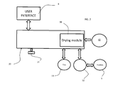
Fig. 2 is a schematic diagram of some of the components of the laundry dryer offig. 1 ; -
Fig. 3 is a flow chart of the method of the invention; -
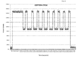
Fig. 4 is a graph showing the power consumed vs. time in a drying cycle of the laundry dryer according to the invention; -
Figs. 5a and 5b are graphs representing the power consumed vs. the time and the temperature vs. the time, respectively, of a non cotton drying cycle according to the prior art; -
Fig. 6a and 6b are graphs representing the power consumed vs. the time and the temperature vs. the time of the same non cotton drying cycle of the graphs according tofigs. 5a and 5b , respectively, but according to the method of the invention. - With initial reference to
fig. 1 , a laundry dryer according to the present invention is globally indicated with 100. -
Laundry dryer 100 is in the depicted drawing a washer dryer, however - as mentioned - the present invention is applicable to all types of dryers.Dryer 100 comprises anouter box casing 2, preferably but not necessarily parallelepiped-shaped, and adrum 3, for example having the shape of a hollow cylinder, for housing the laundry and in general the clothes and garments to be dried.Drum 3 therefore defines a drying chamber for items to be dried. In the depicted drawing, in thedrum 3, clothes are also washed. Thedrum 3 is preferably rotatably fixed to thecasing 2, so that it can rotates around a preferably horizontal axis X (in alternative embodiments, not shown, rotation axis may be vertical or tilted). Access to thedrum 3 is achieved via adoor 4, preferably hinged tocasing 2, which can open and close anopening 4a realized on thecasing 2 itself.Opening 4a preferably facesdrum 3 and it can be sealed bydoor 4. -
Drum 3 defines alateral surface 3c and twoopposite ends opening 4a ofcasing 2.Laundry dryer 100 also comprises anelectrical motor assembly 5 for rotating, on command, revolvingdrum 3 along its axis X insidecasing 2. The coupling between themotor assembly 5 anddrum 3 can be for example via a belt and a drive pulley (also not shown). Preferably,motor 5 is fixed to thedryer 100 belowdrum 3. -
Casing 2, revolvingdrum 3,door 4 andmotor 5 are common parts in the technical field and are considered to be known; therefore they will not be described in details. -
Dryer 100 additionally includes an air delivery system, schematically depicted infig. 1 as a plurality of arrows F showing the path flow of the air through thedryer 100. The air delivery system includes a fan orblower 11, generally driven bymotor 5 in case of a dryer and having an independent servomotor (not shown) in case of a washer-dryer, aheater 9 and pathways for directing air along an air path better detailed below.. - More specifically, depending on the type of dryer under consideration, either air enters into
dryer 100 through one or more air vents realized in thecasing 2, or the air delivery system is a closed circuit, the latter being preferred in case of a washer dryer. In all cases, the relatively cold air travels through aninlet duct 10 reaching theheater 9, where it is heated as it passes through, and it is then introduced in therotatable drum 3 via the throughholes 7 located in correspondence to drum 3. During operation, the heated air dries the laundry presentinside drum 3. - Preferably,
heater 9 is located inside casing 2 abovedrum 3 within theduct 10, such as a metal pipe included in the air delivery system, as better detailed below. - Air passes the
whole drum 3 and it exits the same through an exhaust duct (not shown. The air then travels through an internal exhaust tube and it is either vented outside the casing or passes a heat exchanger and then restarts the described path in thedryer 100. According to a different embodiment, In a washer-dryer, a closed-loop drying circuit is present including a suction unit, i.e. thefan 11, driven by an electric motor, and a heat exchanger connected to theheater 9 via a drying duct. - With now reference to
fig. 2 ,dryer 100 also includes auser interface 8 for the user to enter various inputs relative to the dryer's 100 working parameters. For example, among others, the user can insert viainterface 8 the desired drying cycle from a plurality of available cycles. This plurality preferably includes one or more of: - Cotton cycle (or regular or heavy cycle) for items realized in resistant natural fibers, the air heated by heater reaches a relatively high temperature;
- Synthetic cycle (or permanent press or acrylic cycle) for items realized in synthetic fibers, the temperature of the heated air is lower than the temperature in the cotton cycle;
- Delicate cycle (or wool cycle or knit cycle) for items realized in delicate fabric, the temperature is only slightly above room temperature;
- Air fluff for softening or refreshing any garment, the air is not heated or only very mildly.
- All the above cycles, and others which can be available, with the exception of the cotton cycle, are called in the following "non cotton" cycles.
- It has to be understood that additional inputs can be entered using the
user interface 8 by the user. For example information about the amount of load (full load or half load) or the desired dryness "extra dry", "easy ironing", etc) can be inputted as well. - The
user interface 8 is preferably mounted oncasing 2, more preferably in proximity ofaperture 3a, and it can be of any type, i.e. it can include push buttons, knobs, touch screens, touch buttons or a combination thereof. A display may also be present to visualize the chosen setting. - The
dryer 100 includes acontroller 20 in which the programs for controlling the drying cycles are stored, for example in a memory. Thecontroller 20 selects the program to be executed depending on the inputs received by theuser interface 8 which is electrically connected to it. For example, for each drying cycle, the controller stores the cycle duration or maximum humidity allowed in the dryed clothes and temperature.Controller 20 includes for example a microcontroller. - Each of these programs is called in the following "drying module" 30 in which all instructions for the correct execution of the chosen drying cycle made by the user are present. When the user select a program, the
corresponding drying module 30 is then executed bycontroller 20. - The
controller 20 is also in communication with thefan 11 and with theheater 9 for controlling the same, i.e. for sending command signals in order to switch on/switch off or modulate the same, as better detailed below. - In addition, referring now back to
fig. 1 ,dryer 100 includes atemperature sensor 40, located insidecasing 2 and preferably within the air delivery system, in particularinside duct 10,downstream heater 9 and just before theinlet duct 10 entersdrum 3. Preferably,temperature sensor 40 is a thermistor, such as a negative temperature coefficient (NTC) thermistor, however any other sensor can be used as well. The signal coming from thetemperature sensor 40 is also sent tocontroller 20.Temperature sensor 40 detects the temperature of the heated air which enters thedrum 3 to dry clothes. -
Heater 9, which is preferably an electrical heater, includes a first and asecond heating element fig. 1 as resistors.Heating elements heating elements Heating elements heating element resistor -
Heater 9 is controlled by a heatervariable power supply 50, which is in turn controlled bycontroller 20, that selectively energizes theheater 9, for example switching on or off any of the twoheating elements -
Controller 20, which moreover preferably includes an end ofcycle device 21 better detailed below, thus receives input(s) from the user viainterface 8 and it is operatively coupled tomotor 5 that rotatesdrum 3, and to the motor that drives fan 11 (motor that drivesfan 11 and motor that rotatesdrum 3 might coincide in some preferred embodiments), and to the heatervariable power supply 50 that activates and deactivates theheater 9 to execute the drying cycle selected by the user according to the parameters stored in thecycle module 30 corresponding to the user's selected cycle. - Heater
variable power supply 50 preferably includes one or more switches (not shown), such as relays or triacs, to selectively energizes or de-energizes one or bothheating elements heating elements controllers 20 instruction signals. - According to the invention, the heater
variable power supply 50, when a non cotton cycle has been selected, is apt to energize bothheating elements heater 9, afterwards. In detail, when a non-cotton cycle is selected, and bothheating elements heater 9 is at full power. Conversely, when bothheating elements heater 9 is globally switched off. Moreover, when a second threshold temperature is reached, i.e. the temperature lowers due to the absence of heated air, the heatervariable power supply 50 is apt to energize again bothelements cycle device 21 ofcontroller 20 signals it: the end ofcycle device 21 sends to the controller 20 a signal when the drying cycle is to be terminated. The end ofcycle device 21 can include for example a timer, so the cycle is endend when the timer reaches the selected cyle duration (i.e. the wool drying cycle is set in thedrying module 30 to last 50 minutes and after 50 min the timer sends to the controller a signal to interrupt the cycle), or it can include a humidity/moisture sensor (not visible in the appended figures) which measures the desired humidity of the laundry in thedrum 3. When the humidity of the laundry has reached a desired level, i.e. it equal or below a certain humidity threshold (which might be different depending on the cycle), the sensor sends a signal to thecontroller 20 in order to terminate the drying cycle. The humidity/moisture sensor can be for example a thermistor such as a NTC thermistor and it translates a value of humidity into an electronic signal. In all these cases, the end ofcycle device 21 is activated when the selected pre-determined humidity (and this pre determined value can be stored for example in module 30) of the laundry is detected. - Alternatively, a combination of the two is possible: a pre-determined cycle duration might be set in the
controller 20, but this duration can be changed during the cycle itself depending on the output of the humidity/moister sensor. - The first and second threshold temperatures depend preferably on the user's selected drying cycle. Selecting the cycle may also select the cycle duration and velocity of rotation of the drum. Other parameters can be fixed as well, and they are all stored in the
cycle module 30 of the respective selected cycle. - Referring to
fig. 3 , the method of the invention to control a drying cycle operates as follows. Thedryer 100 is switched on (phase 1) or anyhow activated and loaded with the garments to be dried. Alternatively, in case of a washer-dryer, the dryer is already loaded with the just washed items. - The selected cycle is imputed by the user via the
interface 8 and read by the controller 20 (phase 2). According to the input, the chosen dryingcycle module 30 is then selected by thecontroller 20 and the various parameters, i.e. cycle duration or desired clothes' dryness (i.e. maximum humidity), cycle working temperature, etc, are then loaded from the memory (all these parameters can be for example included in the cycle module 30). - Then, regardless of the inputted cycle, preferably the
controller 20 activatesheater 9 at the maximum available power ("full power"), i.e. it commands heatervariable power supply 50 to energize bothheating elements - In
phase 4, it is then checked whether the inputted cycle is a cotton cycle. In case it is not a cotton cycle, a first threshold temperature T1 is set and it is then checked whether this first threshold temperature has been reached (phase 5). As said, T1 depends on the selected non cotton cycle and can vary depending on the chosen cycle. It is to be noted that during this checking phase, bothheating elements heating elements elements sensor 40 is also performed at regular intervals, for example every 10 milliseconds. T1 is the air temperature read by the controller viasensor 40 and it is preferably measured downstream of the heater and substantially at the entrance of thedrum 3 wheresensor 40 is present. It is the "working temperature" of the cycle, i.e. the desired temperature to be kept during this specific drying cycle. - When the first threshold temperature is reached, according to
phase 6, thecontroller 20 commands the heatervariable power supply 50 to switch off theheater 9 in its entirety, i.e. bothheating elements heater 9 is switched off. The temperature of the air starts then to slowly lower; at the entrance of the drum this temperature is continuously checked bysensor 40 and, when thecontroller 20 receives from sensor 40 a signal indicating a temperature lower than a second threshold temperature T2 (phase 7), i.e. the temperature is too cold, it sends a command to heatervariable power supply 50 so that both heating elements are energized again (back to phase 3) and theheater 9 is again at full power. - The first and the second threshold temperatures T1 and T2 can also be substantially identical: when the
heater 9 is switched off there is still a transient time period in which, due to hysteresis effects, the temperature within the drum still raises, therefore T1 is not the maximum reached temperature and can thus be considered also a suitable temperature below which theheater 9 has to be switched on again. A possible first/second threshold temperature for a synthetic cycle is for example 65° C. The results of the method of the invention are depicted infigs. 6a and 6b , where in the first graph offig. 6a the power dissipated versus time is shown. In the preferred embodiment, eachheating element fig. 6b : when a temperature of circa 95° C (this temperature is higher than the temperature of the air in the drum which should be as said of about 65°C)is reached, the heater is switched off. The temperature still rises and then lowers, and then when the same temperature of circa 95° C is reached, both heating elements are switched on again and the graph offig. 6a rises consequently. Comparing the graphs offig. 6b with the graph offig. 5b , it is evident that the working temperature of the air in the drum is reached in a quicker way using the method and the dryer of the invention. This allows shortening the whole drying cycle. A non-cotton drying cycle up to 20°/ shorter can be achieved. - The dryer of the invention also includes preferably a standard normal cotton cycle stored in the
controller 20. Therefore, if inphase 4 the answer is "yes", then a different third threshold temperature T3, higher than the first threshold temperature T1 of the non-cotton cycle, is set using thecorresponding drying module 30 of the cotton cycle and it is checked whether this higher third threshold temperature is reached (phase 8). - In case the third threshold temperature has been reached, in
phase 9 then a command from thecontroller 20 is sent to the heatervariable power supply 50 so that the latter switches off one of the twoheating elements heating elements - If a fourth threshold temperature T4 is then reached, which is the minimum acceptable working temperature, the second heating element is switched on again, going back to
phase 4 of the method of the invention. During the cotton cycle, therefore, there is always aheating element - A graph of the result of this cycle is given in
fig. 4 . Comparing this graph with graph 6a, it is clear that in the non-cotton cycle either the power is "full power" or it is equal to zero, while in the cotton cycle there is always power consumed. - Phases 5-8 and phases 9-11 are repeated for all the duration of the drying cycle. As already mentioned, the total duration of a cycle can be a parameter which is stored in the memory of the
controller 20 and set when the dryingmodule 30 has been selected by the user, or it can be determined during the cycle itself. Example - In a washer dryer a synthetic drying cycle has been selected and 3 kg of synthetic fabric has been washed and then dried. The threshold temperatures are T1 = T2 = 65 °C. The synthetic drying cycle according to the teaching of the prior art has lasted 130 minutes (see graphs of
figs. 5a and 5b ), while the same cycle according to the teaching of the invention has lasted 115 minutes.
Claims (15)
- A dryer (100) for drying fabric items according to a plurality of drying cycles, said plurality including at least a non-cotton cycle, comprising:o A drying chamber (3) for receiving fabric items to be dried;o An air circulation system to force air through the drying chamber (3);o A heater (9) to heat the air in the air circulation system, said heater including a first and a second heating element (9a,9b);o A user interface (8) apt to receive input from a user to select a drying cycle from said plurality;o A temperature sensor (40) located within said dryer (100) to sense the temperature of said heated air;o A controller (20) operably coupled to the heater (9), to the user interface (8), and to the temperature sensor (40), said controller being apt to receive from the user interface (8) an input relative to the selected drying cycle and from said temperature sensor (40) a temperature value;o Characterized in that it also comprises a heater variable power supply (50) controlled by said controller (20), said variable power supply (50) being adapted, when a non-cotton cycle has been selected, to switch on both said first and said second heating elements (9a,9b) till a first threshold temperature (T1) has been reached, and to switch off both said first and second heating elements (9a,9b) afterwards.
- The dryer (100) of claim 1, wherein said variable power supply (50) is apt to switch on again both first and second heating elements (9a,9b) when a second threshold temperature (T2) has been subsequently reached.
- The dryer according to claim 1 or 2, wherein said heater (9) is at full power when said first and said second heating elements (9a,9b) are switched on.
- The dryer according to any of the preceding claims, wherein said heater (9) is wholly switched off when said first and said second heating elements (9a,9b) are switched off.
- The dryer (100) of any of the preceding claims , wherein said controller (20) includes an end of the cycle device(21) to signal the end of the selected cycle, and wherein said variable power supply (50) is apt to repeat the actions ofo switching on both heating elements (9a,9b), when a non-cotton cycle has been selected, till a first threshold temperature (T1) has been reached;o switching off both said first and second heating elements (9a,9b) afterwards, ando switching on again both first and second heating elements (9a,9b) when a second threshold temperature (T2) has been subsequently reached,till the end of the drying cycle as indicated by said end of the cycle device(21).
- The dryer (100) of any of the preceding claims, wherein said non cotton drying cycle is a synthetic drying cycle.
- The dryer (100) of any of the preceding claims, wherein said first (T1) and said second threshold temperature (T2) are the substantially the same temperature.
- The dryer (100) of any of the preceding claims, wherein said temperature sensor (40) is located in said air circulation system downstream of said heater (9) in proximity of the entrance of the heated air into the drum (3).
- The dryer (100) of any of the preceding claims, wherein said first and said second heating element (9a,9b) have the same heating power capacity.
- The dryer (100) of any of the preceding claims, wherein said plurality of drying cycles includes a cotton cycle and said variable power supply (50) is adapted, when said cotton cycle has been selected, to switch on both said first and said second heating elements (9a,9b) till a third threshold temperature (T3) has been reached, and to switch off only one of said first and second heating elements (9a,9b) afterwards.
- A method to control a drying cycle of a dryer (100), said dryer (100) includingo A drying chamber (3) for receiving fabric items to be dried;o An air circulation system to force air through the drying chamber (3);o A heater (9) to heat the air in the air circulation system, said heater including a first and a second heating element (9a,9b);Said method comprising:o Selecting a drying cycle from a plurality of drying cycles, said plurality including at least a non-cotton cycle;o Switching on both first and second heating element (9a,9b) till a first threshold temperature (T1) is reached;o Switching off both first and second heating element (9a,9b) after the first threshold temperature (T1) has been reached, if a non-cotton drying cycle has been selected.
- The method of claim 13, including, after switching off both said first and said second heating elements:o Switching on both said first and said second heating elements after a second threshold temperature (T2) is reached.
- The method of claim 14, including the actions of
Repeating the actions of:o switching on both heating elements (9a,9b) till a first threshold temperature (T1) has been reached;o switching off both said first and second heating elements (9a,9b) afterwards, if a non-cotton drying cycle has been selected, ando switching on again both first and second heating elements (9a,9b) when a second threshold temperature (T2) has been subsequently reached,till the end of the selected cycle. - The method of any of claims 13-15, wherein said plurality of drying cycles includes a cotton cycle, comprising:o when said cotton cycle has been selected, switching on both said first and said second heating elements (9a,9b) till a third threshold temperature (T3) has been reached, and to switch off only one of said first and second heating elements (9a,9b) afterwards.
- The method according to claim 16, including:o switching on again both first and second heating elements (9a,9b) when a fourth threshold temperature (T4) has been subsequently reached.
Priority Applications (1)
| Application Number | Priority Date | Filing Date | Title |
|---|---|---|---|
| EP11195812.0A EP2610400B1 (en) | 2011-12-27 | 2011-12-27 | Dryer and method to control a drying cycle |
Applications Claiming Priority (1)
| Application Number | Priority Date | Filing Date | Title |
|---|---|---|---|
| EP11195812.0A EP2610400B1 (en) | 2011-12-27 | 2011-12-27 | Dryer and method to control a drying cycle |
Publications (2)
| Publication Number | Publication Date |
|---|---|
| EP2610400A1 true EP2610400A1 (en) | 2013-07-03 |
| EP2610400B1 EP2610400B1 (en) | 2018-12-05 |
Family
ID=45478121
Family Applications (1)
| Application Number | Title | Priority Date | Filing Date |
|---|---|---|---|
| EP11195812.0A Active EP2610400B1 (en) | 2011-12-27 | 2011-12-27 | Dryer and method to control a drying cycle |
Country Status (1)
| Country | Link |
|---|---|
| EP (1) | EP2610400B1 (en) |
Cited By (3)
| Publication number | Priority date | Publication date | Assignee | Title |
|---|---|---|---|---|
| US20160273151A1 (en) * | 2015-03-20 | 2016-09-22 | Whirlpool Corporation | Method for drying laundry in a laundry treating appliance |
| EP3138954A1 (en) * | 2015-09-06 | 2017-03-08 | BSH Hausgeräte GmbH | Laundry care machine and method for caring laundry by using the same |
| EP3348706A1 (en) * | 2017-01-13 | 2018-07-18 | LG Electronics Inc. -1- | Control method of laundry treatment apparatus and laundry treatment apparatus performing the same |
Citations (7)
| Publication number | Priority date | Publication date | Assignee | Title |
|---|---|---|---|---|
| EP0362676A2 (en) | 1988-10-06 | 1990-04-11 | INDUSTRIE ZANUSSI S.p.A. | A laundry drying control device for a clothes drier |
| US4991313A (en) * | 1990-01-22 | 1991-02-12 | White Consolidated Industries, Inc. | Gradual heat reduction for a clothes dryer |
| GB2296793A (en) | 1994-12-30 | 1996-07-10 | Bosch Siemens Hausgeraete | Method of contrplling drying operation of a drier |
| US5649372A (en) * | 1996-03-14 | 1997-07-22 | American Dryer Corporation | Drying cycle controller for controlling drying as a function of humidity and temperature |
| EP1076128A2 (en) | 1999-07-27 | 2001-02-14 | Crosslee PLC | A tumble dryer |
| US20040099655A1 (en) * | 2000-04-28 | 2004-05-27 | Constantino Mariotti | Method for drying laundry and machine implementing such a method |
| US20080210769A1 (en) | 2006-10-09 | 2008-09-04 | Lg Electronics Inc. | Heating system, drying machine having the heating system, and method of controlling the heating system |
-
2011
- 2011-12-27 EP EP11195812.0A patent/EP2610400B1/en active Active
Patent Citations (7)
| Publication number | Priority date | Publication date | Assignee | Title |
|---|---|---|---|---|
| EP0362676A2 (en) | 1988-10-06 | 1990-04-11 | INDUSTRIE ZANUSSI S.p.A. | A laundry drying control device for a clothes drier |
| US4991313A (en) * | 1990-01-22 | 1991-02-12 | White Consolidated Industries, Inc. | Gradual heat reduction for a clothes dryer |
| GB2296793A (en) | 1994-12-30 | 1996-07-10 | Bosch Siemens Hausgeraete | Method of contrplling drying operation of a drier |
| US5649372A (en) * | 1996-03-14 | 1997-07-22 | American Dryer Corporation | Drying cycle controller for controlling drying as a function of humidity and temperature |
| EP1076128A2 (en) | 1999-07-27 | 2001-02-14 | Crosslee PLC | A tumble dryer |
| US20040099655A1 (en) * | 2000-04-28 | 2004-05-27 | Constantino Mariotti | Method for drying laundry and machine implementing such a method |
| US20080210769A1 (en) | 2006-10-09 | 2008-09-04 | Lg Electronics Inc. | Heating system, drying machine having the heating system, and method of controlling the heating system |
Cited By (8)
| Publication number | Priority date | Publication date | Assignee | Title |
|---|---|---|---|---|
| US20160273151A1 (en) * | 2015-03-20 | 2016-09-22 | Whirlpool Corporation | Method for drying laundry in a laundry treating appliance |
| US10138590B2 (en) * | 2015-03-20 | 2018-11-27 | Whirlpool Corporation | Method for drying laundry in a laundry treating appliance |
| US20190062986A1 (en) * | 2015-03-20 | 2019-02-28 | Whirlpool Corporation | Method for drying laundry in a laundry treating appliance |
| US10815611B2 (en) | 2015-03-20 | 2020-10-27 | Whirlpool Corporation | Method for drying laundry in a laundry treating appliance |
| US11674252B2 (en) | 2015-03-20 | 2023-06-13 | Whirlpool Corporation | Method for drying laundry in a laundry treating appliance |
| EP3138954A1 (en) * | 2015-09-06 | 2017-03-08 | BSH Hausgeräte GmbH | Laundry care machine and method for caring laundry by using the same |
| EP3348706A1 (en) * | 2017-01-13 | 2018-07-18 | LG Electronics Inc. -1- | Control method of laundry treatment apparatus and laundry treatment apparatus performing the same |
| US10533277B2 (en) | 2017-01-13 | 2020-01-14 | Lg Electronics Inc. | Control method of laundry treatment apparatus |
Also Published As
| Publication number | Publication date |
|---|---|
| EP2610400B1 (en) | 2018-12-05 |
Similar Documents
| Publication | Publication Date | Title |
|---|---|---|
| EP2630289B1 (en) | Washing machine and control method thereof | |
| CA2446359C (en) | Clothes dryer apparatus and method | |
| CN104040066B (en) | appliance for drying clothes | |
| AU2012364355B2 (en) | Appliance for drying laundry | |
| KR101414625B1 (en) | Dryer | |
| US8819958B2 (en) | End of cycle detection for a laundry treating appliance | |
| EP2636788B1 (en) | Clothes dryer and washer/dryer | |
| US8555522B2 (en) | Laundry treating appliance with inlet temperature compensation | |
| EP2935687B1 (en) | A method for controlling a laundry drying machine and a corresponding laundry drying machine | |
| US20090172965A1 (en) | Household appliance | |
| CA2446625C (en) | Clothes dryer apparatus and method | |
| CN104870710A (en) | Method of operating a heat pump laundry dryer and heat pump laundry dryer or heat pump washing machine having drying function | |
| KR20090033593A (en) | Home appliance and its control method | |
| US20200157731A1 (en) | Method to control operation of a laundry dryer | |
| KR20080058590A (en) | Dryer Control Method | |
| KR101276041B1 (en) | apparatus for drying laundary and controlling method of the same | |
| CN102037178B (en) | Dryer and control method for same | |
| US9027258B2 (en) | Laundry treating appliance with controlled cycle time | |
| US9322127B2 (en) | Method of operating a home appliance | |
| EP2610400B1 (en) | Dryer and method to control a drying cycle | |
| KR20090052691A (en) | Dryer and its control method | |
| US9593442B2 (en) | Method to control a drying cycle of a laundry treating appliance | |
| JP2019187484A (en) | Dryer and washing and drying machine | |
| KR101168888B1 (en) | Method for compensating electric power interrruption in clothes dryer | |
| CN115698417B (en) | Method for operating a laundry dryer equipped with a heat pump system and laundry dryer implementing said method |
Legal Events
| Date | Code | Title | Description |
|---|---|---|---|
| PUAI | Public reference made under article 153(3) epc to a published international application that has entered the european phase |
Free format text: ORIGINAL CODE: 0009012 |
|
| AK | Designated contracting states |
Kind code of ref document: A1 Designated state(s): AL AT BE BG CH CY CZ DE DK EE ES FI FR GB GR HR HU IE IS IT LI LT LU LV MC MK MT NL NO PL PT RO RS SE SI SK SM TR |
|
| AX | Request for extension of the european patent |
Extension state: BA ME |
|
| 17P | Request for examination filed |
Effective date: 20140103 |
|
| RBV | Designated contracting states (corrected) |
Designated state(s): AL AT BE BG CH CY CZ DE DK EE ES FI FR GB GR HR HU IE IS IT LI LT LU LV MC MK MT NL NO PL PT RO RS SE SI SK SM TR |
|
| GRAP | Despatch of communication of intention to grant a patent |
Free format text: ORIGINAL CODE: EPIDOSNIGR1 |
|
| STAA | Information on the status of an ep patent application or granted ep patent |
Free format text: STATUS: GRANT OF PATENT IS INTENDED |
|
| INTG | Intention to grant announced |
Effective date: 20180706 |
|
| GRAS | Grant fee paid |
Free format text: ORIGINAL CODE: EPIDOSNIGR3 |
|
| GRAA | (expected) grant |
Free format text: ORIGINAL CODE: 0009210 |
|
| GRAA | (expected) grant |
Free format text: ORIGINAL CODE: 0009210 |
|
| STAA | Information on the status of an ep patent application or granted ep patent |
Free format text: STATUS: THE PATENT HAS BEEN GRANTED |
|
| AK | Designated contracting states |
Kind code of ref document: B1 Designated state(s): AL AT BE BG CH CY CZ DE DK EE ES FI FR GB GR HR HU IE IS IT LI LT LU LV MC MK MT NL NO PL PT RO RS SE SI SK SM TR |
|
| REG | Reference to a national code |
Ref country code: GB Ref legal event code: FG4D |
|
| REG | Reference to a national code |
Ref country code: CH Ref legal event code: EP |
|
| REG | Reference to a national code |
Ref country code: AT Ref legal event code: REF Ref document number: 1073217 Country of ref document: AT Kind code of ref document: T Effective date: 20181215 |
|
| REG | Reference to a national code |
Ref country code: DE Ref legal event code: R096 Ref document number: 602011054475 Country of ref document: DE |
|
| REG | Reference to a national code |
Ref country code: IE Ref legal event code: FG4D |
|
| REG | Reference to a national code |
Ref country code: NL Ref legal event code: MP Effective date: 20181205 |
|
| REG | Reference to a national code |
Ref country code: AT Ref legal event code: MK05 Ref document number: 1073217 Country of ref document: AT Kind code of ref document: T Effective date: 20181205 |
|
| REG | Reference to a national code |
Ref country code: LT Ref legal event code: MG4D |
|
| PG25 | Lapsed in a contracting state [announced via postgrant information from national office to epo] |
Ref country code: LV Free format text: LAPSE BECAUSE OF FAILURE TO SUBMIT A TRANSLATION OF THE DESCRIPTION OR TO PAY THE FEE WITHIN THE PRESCRIBED TIME-LIMIT Effective date: 20181205 Ref country code: AT Free format text: LAPSE BECAUSE OF FAILURE TO SUBMIT A TRANSLATION OF THE DESCRIPTION OR TO PAY THE FEE WITHIN THE PRESCRIBED TIME-LIMIT Effective date: 20181205 Ref country code: FI Free format text: LAPSE BECAUSE OF FAILURE TO SUBMIT A TRANSLATION OF THE DESCRIPTION OR TO PAY THE FEE WITHIN THE PRESCRIBED TIME-LIMIT Effective date: 20181205 Ref country code: BG Free format text: LAPSE BECAUSE OF FAILURE TO SUBMIT A TRANSLATION OF THE DESCRIPTION OR TO PAY THE FEE WITHIN THE PRESCRIBED TIME-LIMIT Effective date: 20190305 Ref country code: NO Free format text: LAPSE BECAUSE OF FAILURE TO SUBMIT A TRANSLATION OF THE DESCRIPTION OR TO PAY THE FEE WITHIN THE PRESCRIBED TIME-LIMIT Effective date: 20190305 Ref country code: HR Free format text: LAPSE BECAUSE OF FAILURE TO SUBMIT A TRANSLATION OF THE DESCRIPTION OR TO PAY THE FEE WITHIN THE PRESCRIBED TIME-LIMIT Effective date: 20181205 Ref country code: ES Free format text: LAPSE BECAUSE OF FAILURE TO SUBMIT A TRANSLATION OF THE DESCRIPTION OR TO PAY THE FEE WITHIN THE PRESCRIBED TIME-LIMIT Effective date: 20181205 Ref country code: LT Free format text: LAPSE BECAUSE OF FAILURE TO SUBMIT A TRANSLATION OF THE DESCRIPTION OR TO PAY THE FEE WITHIN THE PRESCRIBED TIME-LIMIT Effective date: 20181205 |
|
| PG25 | Lapsed in a contracting state [announced via postgrant information from national office to epo] |
Ref country code: SE Free format text: LAPSE BECAUSE OF FAILURE TO SUBMIT A TRANSLATION OF THE DESCRIPTION OR TO PAY THE FEE WITHIN THE PRESCRIBED TIME-LIMIT Effective date: 20181205 Ref country code: GR Free format text: LAPSE BECAUSE OF FAILURE TO SUBMIT A TRANSLATION OF THE DESCRIPTION OR TO PAY THE FEE WITHIN THE PRESCRIBED TIME-LIMIT Effective date: 20190306 Ref country code: AL Free format text: LAPSE BECAUSE OF FAILURE TO SUBMIT A TRANSLATION OF THE DESCRIPTION OR TO PAY THE FEE WITHIN THE PRESCRIBED TIME-LIMIT Effective date: 20181205 Ref country code: RS Free format text: LAPSE BECAUSE OF FAILURE TO SUBMIT A TRANSLATION OF THE DESCRIPTION OR TO PAY THE FEE WITHIN THE PRESCRIBED TIME-LIMIT Effective date: 20181205 |
|
| PG25 | Lapsed in a contracting state [announced via postgrant information from national office to epo] |
Ref country code: NL Free format text: LAPSE BECAUSE OF FAILURE TO SUBMIT A TRANSLATION OF THE DESCRIPTION OR TO PAY THE FEE WITHIN THE PRESCRIBED TIME-LIMIT Effective date: 20181205 |
|
| PG25 | Lapsed in a contracting state [announced via postgrant information from national office to epo] |
Ref country code: PT Free format text: LAPSE BECAUSE OF FAILURE TO SUBMIT A TRANSLATION OF THE DESCRIPTION OR TO PAY THE FEE WITHIN THE PRESCRIBED TIME-LIMIT Effective date: 20190405 Ref country code: CZ Free format text: LAPSE BECAUSE OF FAILURE TO SUBMIT A TRANSLATION OF THE DESCRIPTION OR TO PAY THE FEE WITHIN THE PRESCRIBED TIME-LIMIT Effective date: 20181205 Ref country code: PL Free format text: LAPSE BECAUSE OF FAILURE TO SUBMIT A TRANSLATION OF THE DESCRIPTION OR TO PAY THE FEE WITHIN THE PRESCRIBED TIME-LIMIT Effective date: 20181205 |
|
| REG | Reference to a national code |
Ref country code: CH Ref legal event code: PL |
|
| PG25 | Lapsed in a contracting state [announced via postgrant information from national office to epo] |
Ref country code: SK Free format text: LAPSE BECAUSE OF FAILURE TO SUBMIT A TRANSLATION OF THE DESCRIPTION OR TO PAY THE FEE WITHIN THE PRESCRIBED TIME-LIMIT Effective date: 20181205 Ref country code: IS Free format text: LAPSE BECAUSE OF FAILURE TO SUBMIT A TRANSLATION OF THE DESCRIPTION OR TO PAY THE FEE WITHIN THE PRESCRIBED TIME-LIMIT Effective date: 20190405 Ref country code: RO Free format text: LAPSE BECAUSE OF FAILURE TO SUBMIT A TRANSLATION OF THE DESCRIPTION OR TO PAY THE FEE WITHIN THE PRESCRIBED TIME-LIMIT Effective date: 20181205 Ref country code: EE Free format text: LAPSE BECAUSE OF FAILURE TO SUBMIT A TRANSLATION OF THE DESCRIPTION OR TO PAY THE FEE WITHIN THE PRESCRIBED TIME-LIMIT Effective date: 20181205 Ref country code: SM Free format text: LAPSE BECAUSE OF FAILURE TO SUBMIT A TRANSLATION OF THE DESCRIPTION OR TO PAY THE FEE WITHIN THE PRESCRIBED TIME-LIMIT Effective date: 20181205 Ref country code: LU Free format text: LAPSE BECAUSE OF NON-PAYMENT OF DUE FEES Effective date: 20181227 |
|
| REG | Reference to a national code |
Ref country code: DE Ref legal event code: R097 Ref document number: 602011054475 Country of ref document: DE |
|
| REG | Reference to a national code |
Ref country code: IE Ref legal event code: MM4A |
|
| REG | Reference to a national code |
Ref country code: BE Ref legal event code: MM Effective date: 20181231 |
|
| PLBE | No opposition filed within time limit |
Free format text: ORIGINAL CODE: 0009261 |
|
| STAA | Information on the status of an ep patent application or granted ep patent |
Free format text: STATUS: NO OPPOSITION FILED WITHIN TIME LIMIT |
|
| PG25 | Lapsed in a contracting state [announced via postgrant information from national office to epo] |
Ref country code: FR Free format text: LAPSE BECAUSE OF NON-PAYMENT OF DUE FEES Effective date: 20190205 Ref country code: SI Free format text: LAPSE BECAUSE OF FAILURE TO SUBMIT A TRANSLATION OF THE DESCRIPTION OR TO PAY THE FEE WITHIN THE PRESCRIBED TIME-LIMIT Effective date: 20181205 Ref country code: IE Free format text: LAPSE BECAUSE OF NON-PAYMENT OF DUE FEES Effective date: 20181227 Ref country code: MC Free format text: LAPSE BECAUSE OF FAILURE TO SUBMIT A TRANSLATION OF THE DESCRIPTION OR TO PAY THE FEE WITHIN THE PRESCRIBED TIME-LIMIT Effective date: 20181205 Ref country code: DK Free format text: LAPSE BECAUSE OF FAILURE TO SUBMIT A TRANSLATION OF THE DESCRIPTION OR TO PAY THE FEE WITHIN THE PRESCRIBED TIME-LIMIT Effective date: 20181205 |
|
| 26N | No opposition filed |
Effective date: 20190906 |
|
| REG | Reference to a national code |
Ref country code: DE Ref legal event code: R079 Ref document number: 602011054475 Country of ref document: DE Free format text: PREVIOUS MAIN CLASS: D06F0058280000 Ipc: D06F0058300000 |
|
| GBPC | Gb: european patent ceased through non-payment of renewal fee |
Effective date: 20190305 |
|
| PG25 | Lapsed in a contracting state [announced via postgrant information from national office to epo] |
Ref country code: BE Free format text: LAPSE BECAUSE OF NON-PAYMENT OF DUE FEES Effective date: 20181231 |
|
| PG25 | Lapsed in a contracting state [announced via postgrant information from national office to epo] |
Ref country code: CH Free format text: LAPSE BECAUSE OF NON-PAYMENT OF DUE FEES Effective date: 20181231 Ref country code: LI Free format text: LAPSE BECAUSE OF NON-PAYMENT OF DUE FEES Effective date: 20181231 |
|
| PG25 | Lapsed in a contracting state [announced via postgrant information from national office to epo] |
Ref country code: GB Free format text: LAPSE BECAUSE OF NON-PAYMENT OF DUE FEES Effective date: 20190305 Ref country code: MT Free format text: LAPSE BECAUSE OF NON-PAYMENT OF DUE FEES Effective date: 20181227 |
|
| PG25 | Lapsed in a contracting state [announced via postgrant information from national office to epo] |
Ref country code: TR Free format text: LAPSE BECAUSE OF FAILURE TO SUBMIT A TRANSLATION OF THE DESCRIPTION OR TO PAY THE FEE WITHIN THE PRESCRIBED TIME-LIMIT Effective date: 20181205 |
|
| PG25 | Lapsed in a contracting state [announced via postgrant information from national office to epo] |
Ref country code: CY Free format text: LAPSE BECAUSE OF FAILURE TO SUBMIT A TRANSLATION OF THE DESCRIPTION OR TO PAY THE FEE WITHIN THE PRESCRIBED TIME-LIMIT Effective date: 20181205 Ref country code: MK Free format text: LAPSE BECAUSE OF NON-PAYMENT OF DUE FEES Effective date: 20181205 Ref country code: HU Free format text: LAPSE BECAUSE OF FAILURE TO SUBMIT A TRANSLATION OF THE DESCRIPTION OR TO PAY THE FEE WITHIN THE PRESCRIBED TIME-LIMIT; INVALID AB INITIO Effective date: 20111227 |
|
| P01 | Opt-out of the competence of the unified patent court (upc) registered |
Effective date: 20230625 |
|
| PGFP | Annual fee paid to national office [announced via postgrant information from national office to epo] |
Ref country code: IT Payment date: 20251218 Year of fee payment: 15 |
|
| PGFP | Annual fee paid to national office [announced via postgrant information from national office to epo] |
Ref country code: DE Payment date: 20251229 Year of fee payment: 15 |