EP0362676A2 - A laundry drying control device for a clothes drier - Google Patents
A laundry drying control device for a clothes drier Download PDFInfo
- Publication number
- EP0362676A2 EP0362676A2 EP89117773A EP89117773A EP0362676A2 EP 0362676 A2 EP0362676 A2 EP 0362676A2 EP 89117773 A EP89117773 A EP 89117773A EP 89117773 A EP89117773 A EP 89117773A EP 0362676 A2 EP0362676 A2 EP 0362676A2
- Authority
- EP
- European Patent Office
- Prior art keywords
- drying
- heating element
- control device
- comparator
- output
- Prior art date
- Legal status (The legal status is an assumption and is not a legal conclusion. Google has not performed a legal analysis and makes no representation as to the accuracy of the status listed.)
- Granted
Links
Images
Classifications
-
- D—TEXTILES; PAPER
- D06—TREATMENT OF TEXTILES OR THE LIKE; LAUNDERING; FLEXIBLE MATERIALS NOT OTHERWISE PROVIDED FOR
- D06F—LAUNDERING, DRYING, IRONING, PRESSING OR FOLDING TEXTILE ARTICLES
- D06F34/00—Details of control systems for washing machines, washer-dryers or laundry dryers
- D06F34/08—Control circuits or arrangements thereof
-
- D—TEXTILES; PAPER
- D06—TREATMENT OF TEXTILES OR THE LIKE; LAUNDERING; FLEXIBLE MATERIALS NOT OTHERWISE PROVIDED FOR
- D06F—LAUNDERING, DRYING, IRONING, PRESSING OR FOLDING TEXTILE ARTICLES
- D06F2103/00—Parameters monitored or detected for the control of domestic laundry washing machines, washer-dryers or laundry dryers
- D06F2103/02—Characteristics of laundry or load
- D06F2103/08—Humidity
-
- D—TEXTILES; PAPER
- D06—TREATMENT OF TEXTILES OR THE LIKE; LAUNDERING; FLEXIBLE MATERIALS NOT OTHERWISE PROVIDED FOR
- D06F—LAUNDERING, DRYING, IRONING, PRESSING OR FOLDING TEXTILE ARTICLES
- D06F2103/00—Parameters monitored or detected for the control of domestic laundry washing machines, washer-dryers or laundry dryers
- D06F2103/02—Characteristics of laundry or load
- D06F2103/08—Humidity
- D06F2103/10—Humidity expressed as capacitance or resistance
-
- D—TEXTILES; PAPER
- D06—TREATMENT OF TEXTILES OR THE LIKE; LAUNDERING; FLEXIBLE MATERIALS NOT OTHERWISE PROVIDED FOR
- D06F—LAUNDERING, DRYING, IRONING, PRESSING OR FOLDING TEXTILE ARTICLES
- D06F2103/00—Parameters monitored or detected for the control of domestic laundry washing machines, washer-dryers or laundry dryers
- D06F2103/28—Air properties
- D06F2103/32—Temperature
-
- D—TEXTILES; PAPER
- D06—TREATMENT OF TEXTILES OR THE LIKE; LAUNDERING; FLEXIBLE MATERIALS NOT OTHERWISE PROVIDED FOR
- D06F—LAUNDERING, DRYING, IRONING, PRESSING OR FOLDING TEXTILE ARTICLES
- D06F2105/00—Systems or parameters controlled or affected by the control systems of washing machines, washer-dryers or laundry dryers
- D06F2105/28—Electric heating
-
- D—TEXTILES; PAPER
- D06—TREATMENT OF TEXTILES OR THE LIKE; LAUNDERING; FLEXIBLE MATERIALS NOT OTHERWISE PROVIDED FOR
- D06F—LAUNDERING, DRYING, IRONING, PRESSING OR FOLDING TEXTILE ARTICLES
- D06F34/00—Details of control systems for washing machines, washer-dryers or laundry dryers
- D06F34/10—Power supply arrangements, e.g. stand-by circuits
-
- D—TEXTILES; PAPER
- D06—TREATMENT OF TEXTILES OR THE LIKE; LAUNDERING; FLEXIBLE MATERIALS NOT OTHERWISE PROVIDED FOR
- D06F—LAUNDERING, DRYING, IRONING, PRESSING OR FOLDING TEXTILE ARTICLES
- D06F58/00—Domestic laundry dryers
- D06F58/32—Control of operations performed in domestic laundry dryers
- D06F58/34—Control of operations performed in domestic laundry dryers characterised by the purpose or target of the control
- D06F58/36—Control of operational steps, e.g. for optimisation or improvement of operational steps depending on the condition of the laundry
- D06F58/38—Control of operational steps, e.g. for optimisation or improvement of operational steps depending on the condition of the laundry of drying, e.g. to achieve the target humidity
Definitions
- This control device further comprises at least one electrical heating element 3 with adjustable power and a moisture control means 4 both realized in the way described below and adapted to effect the heating of the laundry drying air and to predetermine the drying level required for each laundry load, respectively.
Landscapes
- Engineering & Computer Science (AREA)
- Textile Engineering (AREA)
- Drying Of Solid Materials (AREA)
- Control Of Washing Machine And Dryer (AREA)
Abstract
Description
- The present invention relates to an electronic control device for a clothes drier adapted to allow for the run of drying cycles for drying the laundry in a predetermined manner and for limited durations.
- Italian patent application no. 45702 A/88, filed by the same applicant on Jan. 25, 1988, describes a laundry drying control device for a clothes drier comprising a microprocessor containing encoded information on the drying cycles to be selected and adapted to control the run of the selected cycles; first, second and third selector means adapted to select drying cycles with nominal power and with reduced power of a heating element with adjustable power and adapted to keep the heating element switched on for a supplementary period; and integrator means constituted by electrical capacitors connected with two sensor electrodes disposed within the drum of the machine and adapted to be short-circuited by the damp laundry.
- This control device further comprises an electronic comparator adapted to switch on and off the heating element of the machine in accordance with a comparison between the charging voltage level of the integrator means and a predetermined reference voltage level and the microprocessor of the device is designed to generate through one of its outputs a continuous rectangular enabling signal and to send this signal to the microprocessor through a corresponding input, making it pass through the integrator circuit and the second and third selector means.
- The microprocessor is in particular in a position to identify, at the output of the comparator, the absence or presence of the enabling signal when the drying cycles have been selected through the first or second selector means, and an enabling signal identical but complementary to the preceding one when the drying cycles are selected through the third selector means.
- In accordance with the identified enabling signal, the microprocessor thus controls the run of the drying cycles with nominal or reduced power of the heating element or with supplementary switching on of the element.
- The control device thus constituted allows for a correct run of the drying cycles for the laundry in the machine, providing for the heating element to be switched on with the fixed and invariable power for the entire duration of each selected cycle. However, this does not allow for an adaptation of the heating power effectively required for drying the laundry during the run of the cycle, for a power which is variable while the laundry is dried, resulting in higher consumption of electrical power.
- The invention is based on the problem of overcoming the above -mentioned disadvantages and limits by means of a laundry drying control device for a clothes drier realized in such a way as to effect the run of each drying cycle with optimal consumption of electrical power and with a limited duration of the cycle.
- This control device is in particular adapted to switch on the electrical heating element with the maximum heating power during the initial phase of each "acrylic" drying cycle for drying delicate synthetic fabrics, the temperature of the fabrics being slowly increased until the operating value is reached and the heating element being then switched on with reduced power for the entire duration of the cycle.
- Similarly, this control device is in a position to keep the electrical heating element switched on with reduced heating power during the run of the so-called "extra dry" drying cycles for completely drying cotton and resistant synthetic fabrics, having the heating element switched on for a supplementary time period.
- This and other goals are achieved by the inventive device specified in the claims at the end of the patent.
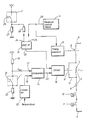
- The features of the invention will become more evident from the following description, intended solely as a nonrestrictive example, with reference to the adjoined drawing showing the block diagram of the inventive control device.
- Referring to this drawing, one can see an electronic laundry drying control device for a clothes drier realized in substantially the same way as the device described in Italian patent application no. 45702 A/88, filed by the same applicant on Jan. 25, 1988, and capable of controlling the automatic run of cycles for drying laundry consisting of cotton and resistant synthetic fabrics, the cycles being performed with the maximum heating power until the predetermined laundry drying level is reached, or keeping the heating element with adjustable power of the machine switched on for a predetermined supplementary period so as to effect complete drying of the laundry (these drying cycles being known as "extra dry cycles").
- This device is also capable of controlling the automatic run of cycles for drying laundry consisting of delicate synthetic fabrics, the cycles being performed with reduced heating power until the predetermined laundry drying level is reached (these drying cycles being known as "acrylic cycles").
- In the present case the control device substantially comprises first and second selector means 1 and 2 constituted by conventional push-button switches disposed in the control panel of the machine and adapted to be operated separately and manually to select the aforesaid "acrylic" drying cycle or the "extra dry" cycle with the heating element of the machine being switched on for a predetermined supplementary period, said device also comprising, as in the case of patent application no 45702 A/88, further selector means (not shown) for selecting "extra dry" drying cycles with the maximum heating power. These selector means shall not be described here since they are not relevant to the effects of the invention.
- This control device further comprises at least one electrical heating element 3 with adjustable power and a moisture control means 4 both realized in the way described below and adapted to effect the heating of the laundry drying air and to predetermine the drying level required for each laundry load, respectively.
- In particular, electrical heating element 3 is subdivided into at least a first and a
second portion conductors 7 and 8 of the electrical circuit of the machine through an electrical contact 9 of the normally closed type and provided for the purposes to be described below, and throughsafety thermostats -
Portions portion 6 of the heating element is energized, a state obtained by short-circuiting theother portion 5 of the heating element due to the closing of anelectrical contact 12 on anelectrical conductor 13 connected to the heads ofportion 5, the closing being performed in the ways described below. - In its turn, moisture control means 4 is constituted by an integrator circuit equipped with a plurality of electrical capacitors collected with limiting resistors, diodes and further electronic components known as such, the circuit being adapted to vary the time constant of the capacitors in accordance with the drying level required by the laundry, and by two sensor electrodes disposed within the rotating drum of the machine (not shown) and connected with the integrator circuit and with the ground of the machine, the electrodes being adapted to be short-circuited by the damp laundry to be dried.
- The integrator circuit and sensor electrodes, which are not represented in the drawing, are identical to the corresponding electrical components described in the above-mentioned Italian patent application no. 45702 A/88 and therefore have the same functions as these components.
- To allow for control of the switching on and off of
portion 5 of the heating element in order to vary the heating power for the purposes and in the ways described below, the present device further comprises anelectronic comparator 14 and a logical ANDgate 15 of the conventional type and adriver 16 or similar driving element controlled alternatively bycomparator 14 or by logical ANDgate 15 for movingelectrical contact 12 associated with the driver from the normal closed position to the open position with respect toconductor 13, in whichstates portion 5 is switched off and on, respectively, with respect toother portion 6 of the heating element. - In particular,
comparator 14 is provided with twoinputs first resistor 19 supplied by a predetermined continuous voltage Vcc, the resistor being adapted in turn to be connected in parallel with asecond resistor 20 that is grounded, due to the closing ofcontact 21 of first selector means 1, the contact being connected with the second resistor, and with a conventionalelectronic converter 22 adapted to detect constantly the temperature levels of the drying air within the clothes drier and to convert these temperature levels into corresponding voltage levels. - The comparator is further provided with an
output 23 connected todriver 16 whose logical level is determined by comparison between a predetermined reference voltage VREF applied toinput 17 of the comparator and generated by the closing ofcontact 21 and a variable voltage generated byconverter 22 during the run of the drying cycle selected through first selector means 1. - The level of reference voltage VREF is in particular selected so as to be identical to the voltage level generated by
converter 22 and applied to input 18 ofcomparator 14 upon attainment of the operating temperature during drying, at which temperature delicate synthetic fabrics are dried in a satisfactory manner without danger of overheating or damage thereto. - In this operative state of
comparator 14, given that both voltages applied toinputs comparator output 23 is thus switched from level 0 tolevel 1, thereby energizingdriver 16 which thus openscontact 12, thereby connectingportions - Conversely, the reference voltage assumes a level higher then the voltage level generated by
converter 22 in accordance with the operating temperature during drying whencontact 21 of selector means 1 is kept in the open position, in which state only voltage Vcc is applied to input 17 ofcomparator 14 throughresistor 19. - In this operative state of
comparator 14, given that both voltages applied toinputs converter 22 remain constant, the level of this voltage being lower then that of the above-mentioned voltage Vcc, it follows thatoutput 23 of the comparator is always kept at logical level 0, in whichstate driver 16 is not energized and keepscontact 12 closed andportion 5 of the heating element therefore short-circuited. - In its turn, logical AND
gate 15 is provided with twoinputs first resistor 26 connected electrically to asecond resistor 27 that is grounded and can be energized by the above-described predetermined continuous voltage Vcc due to the closing ofcontact 28 of second selector means 2, the contact being connected to bothresistors output 29 of moisture control means 4 specified above. - AND
gate 15 is further provided with anoutput 30 connected todriver 16 whose logical level is determined by comparison between the voltage levels applied respectively toinputs - In particular, as soon as the drying cycle is selected
closing contact 28 of selector means 2,input 24 ofAND gate 15 is subjected to predetermined voltage Vcc, while in its turn theother input 25 of the gate is not subjected to an identical predetermined voltage which is drawn byoutput 29 of moisture control means 4, given that the latter generates the voltage only upon attainment of the predetermined drying level for the laundry. - In this operative state of
AND gate 15,output 30 thereof thus remains at logical level 0 and thereforedriver 16 is not energized so thatportion 5 of the heating element is kept short-circuited, in which state there is the maximum drying power of the drying air. - Conversely, as soon as the predetermined drying level for the laundry is reached,
input 25 ofAND gate 15 is also subjected to the predetermined voltage generated by moisture control means 4 and present atoutput 29 thereof, in whichstate output 30 of the gate is switched tological level 1, thereby energizingdriver 16 and thus connecting inseries portions - Finally, the inventive control device further comprises a
timing element 31 or similar conventional-type element connected electrically to output 29 of moisture control means 4 and mechanically to electrical contact 9 in order to allow for closing or opening of the contact, thereby switching heating element 3 on or off in accordance with the absence or presence of the predetermined voltage atinput 29 of the moisture control means. - The modes of functioning of the present control device during the run of the "acrylic" and "extra dry" cycles to be triggered by selector means 1 and 2 will now be described.
- The "acrylic" cycle is triggered by closing
contact 21 of selector means 1 and preparing moisture control means 4 andtiming element 31 to obtain the desired drying level for the laundry. - In this way, reference voltage VREF with a predetermined fixed level and the voltage generated by
converter 22 and proportional to the drying temperature are applied respectively toinputs comparator 14, the initial level of the latter voltage being minimal and lower then that of voltage VREF. - In these states,
output 23 ofcomparator 14 is at logical level 0 so thatdriver 16 remains deenergized, thereby maintainingportion 5 of the heating element short-circuited. In its turn,timing element 31 remains deenergized, given thatoutput 29 of moisture control means 4 is not subjected to the above-mentioned predetermined voltage, since the drying level provided for the laundry has not yet been reached. - Consequently, the timing element keeps electrical contact 9 closed so that only
portion 6 of the heating element is energized, in which state the run of the drying cycle is effected with the maximum heating power and thus with rapid heating of the laundry and of the machine to the corresponding operating temperature. - In this state one thus obtains a considerable reduction of the duration of the total drying cycle without any overheating or damage to the fabrics.
- Thus, as soon as the operating temperature is reached, in which state the voltage generated by
converter 22 has reached reference voltage level VREF,output 23 ofcomparator 14 is switched tological level 1 so thatdriver 16 is energized and openscontact 12, thereby interconnecting inseries portions output 29 of moisture control means 4, thereby energizingtiming element 31 which opens electrical contact 9, thereby switching offportions - In this way, the drying cycle is ended and the machine prepared for the run of the following cooling phase, which is performed in the conventional way and controlled by further electrical components (not shown) of the clothes drier.
- In its turn, the "extra dry" cycle is triggered by closing
contact 28 of selector means 2 and preparing moisture control means 4 andtiming element 31, as above, to obtain the desired drying level for the laundry. - In this way, the predetermined voltage Vcc is applied to input 24 of logical AND
gate 15, while theother input 25 of the gate is not live, given thatoutput 29 of moisture control means 4 is not live either since the drying level provided for the laundry has not yet been reached. In these states,output 30 of logical ANDgate 15 is at logical level 0 so thatdriver 16 remains deenergized, thereby keepingportion 5 of the heating element short-circuited. In its turn,timing element 31 also re mains deenergized and thus effects the switching on ofportion 6 of the heating element only, in the ways and for the purposes already described in the corresponding phase of the "acrylic" drying cycle. - As soon as the drying level provided for the laundry is reached,
output 29 of moisture control means 4 and thus input 25 ofAND gate 15 are subjected to the aforesaid predetermined voltage, so thatoutput 30 of the AND gate is switched tological level 1, thereby energizingdriver 16 which openscontact 12 and thus interconnects inseries portions - At the same time, the presence of the predetermined voltage at
output 29 of moisture control means 4energizes timing element 31 which therefore keeps electrical contact 9 closed and thusportions - At the end of this time period,
timing element 31 automatically opens electrical contact 9, thereby switching offportions - The present control device can be advantageously incorporated in a conventional microprocessor adapted to control the run of all the operative functions of the clothes drier.
Claims (4)
Priority Applications (1)
| Application Number | Priority Date | Filing Date | Title |
|---|---|---|---|
| AT8989117773T ATE104711T1 (en) | 1988-10-06 | 1989-09-26 | DEVICE FOR MONITORING LAUNDRY DRYING IN A LAUNDRY DRYER. |
Applications Claiming Priority (2)
| Application Number | Priority Date | Filing Date | Title |
|---|---|---|---|
| IT8845761A IT1225123B (en) | 1988-10-06 | 1988-10-06 | DRYING CONTROL DEVICE FOR LINEN FOR DRYING MACHINE |
| IT4576188 | 1988-10-06 |
Publications (3)
| Publication Number | Publication Date |
|---|---|
| EP0362676A2 true EP0362676A2 (en) | 1990-04-11 |
| EP0362676A3 EP0362676A3 (en) | 1992-03-11 |
| EP0362676B1 EP0362676B1 (en) | 1994-04-20 |
Family
ID=11258109
Family Applications (1)
| Application Number | Title | Priority Date | Filing Date |
|---|---|---|---|
| EP89117773A Expired - Lifetime EP0362676B1 (en) | 1988-10-06 | 1989-09-26 | A laundry drying control device for a clothes drier |
Country Status (4)
| Country | Link |
|---|---|
| EP (1) | EP0362676B1 (en) |
| AT (1) | ATE104711T1 (en) |
| DE (1) | DE68914765T2 (en) |
| IT (1) | IT1225123B (en) |
Cited By (1)
| Publication number | Priority date | Publication date | Assignee | Title |
|---|---|---|---|---|
| EP2610400A1 (en) | 2011-12-27 | 2013-07-03 | Electrolux Home Products Corporation N.V. | Dryer and method to control a drying cycle |
Families Citing this family (2)
| Publication number | Priority date | Publication date | Assignee | Title |
|---|---|---|---|---|
| US9416476B2 (en) | 2012-05-30 | 2016-08-16 | Whirlpool Corporation | Laundry treating appliance and method of controlling the heater thereof |
| US9139951B2 (en) | 2012-08-06 | 2015-09-22 | Whirlpool Corporation | Laundry treating appliance and method of controlling the heater thereof |
Family Cites Families (3)
| Publication number | Priority date | Publication date | Assignee | Title |
|---|---|---|---|---|
| US3942265A (en) * | 1974-05-09 | 1976-03-09 | General Electric Company | Dryer control arrangement |
| DE2537821A1 (en) * | 1975-08-26 | 1977-03-10 | Miele & Cie | Clothes drier with control according to moisture - with increased heat utilisation and reduced heat in final drying stage |
| DE2904274C2 (en) * | 1979-02-05 | 1982-06-03 | Bosch-Siemens Hausgeraete Gmbh, 7000 Stuttgart | Thermostat-controlled circuit arrangement |
-
1988
- 1988-10-06 IT IT8845761A patent/IT1225123B/en active
-
1989
- 1989-09-26 EP EP89117773A patent/EP0362676B1/en not_active Expired - Lifetime
- 1989-09-26 AT AT8989117773T patent/ATE104711T1/en not_active IP Right Cessation
- 1989-09-26 DE DE68914765T patent/DE68914765T2/en not_active Expired - Fee Related
Cited By (1)
| Publication number | Priority date | Publication date | Assignee | Title |
|---|---|---|---|---|
| EP2610400A1 (en) | 2011-12-27 | 2013-07-03 | Electrolux Home Products Corporation N.V. | Dryer and method to control a drying cycle |
Also Published As
| Publication number | Publication date |
|---|---|
| DE68914765D1 (en) | 1994-05-26 |
| EP0362676A3 (en) | 1992-03-11 |
| DE68914765T2 (en) | 1994-08-04 |
| EP0362676B1 (en) | 1994-04-20 |
| IT8845761A0 (en) | 1988-10-06 |
| ATE104711T1 (en) | 1994-05-15 |
| IT1225123B (en) | 1990-11-02 |
Similar Documents
| Publication | Publication Date | Title |
|---|---|---|
| KR910002190B1 (en) | Control Method of Electric Clothes Dryer | |
| CA1235467A (en) | Control system for a combined appliance | |
| US4320329A (en) | Windshield wiper control circuit | |
| CA2430471C (en) | Clothes dryer over-voltage control apparatus and method | |
| EP1167608A2 (en) | A method and apparatus for power loss detection and saving of operation settings in an appliance | |
| US4751450A (en) | Low cost, protective start from coast circuit | |
| KR100480727B1 (en) | Apparatus for controlling heater of a dryer | |
| US6757988B2 (en) | Control system for a clothes dryer heater | |
| US3864844A (en) | Solid state dryer control | |
| US4642907A (en) | Thermal bias and timer run-out for automatic dryer control | |
| EP0362676B1 (en) | A laundry drying control device for a clothes drier | |
| US3491458A (en) | Electronic control circuit for a dryer with anti-wrinkle | |
| US5175413A (en) | Fail-safe relay drive system for cooking apparatus | |
| US4132008A (en) | Control circuit for drier | |
| US3571941A (en) | Appliance control circuit | |
| US2796679A (en) | Autoamtic clothes dryer control | |
| US4112588A (en) | Drier appliance control | |
| EP0326048B1 (en) | Device for controlling the drying of laundry in a laundry drier | |
| US3330047A (en) | Dryer control | |
| US3624477A (en) | Intermittent control with a normally open thermal switch for windshield wiper system | |
| CA1227263A (en) | Control circuit for gas heated appliance | |
| US3327403A (en) | Dryer control system | |
| US3471939A (en) | Electronic control circuit for a dryer | |
| US3269026A (en) | Dryer control | |
| GB2352498A (en) | A tumble dryer |
Legal Events
| Date | Code | Title | Description |
|---|---|---|---|
| PUAI | Public reference made under article 153(3) epc to a published international application that has entered the european phase |
Free format text: ORIGINAL CODE: 0009012 |
|
| AK | Designated contracting states |
Kind code of ref document: A2 Designated state(s): AT DE FR GB IT SE |
|
| PUAL | Search report despatched |
Free format text: ORIGINAL CODE: 0009013 |
|
| AK | Designated contracting states |
Kind code of ref document: A3 Designated state(s): AT DE FR GB IT SE |
|
| 17P | Request for examination filed |
Effective date: 19920305 |
|
| 17Q | First examination report despatched |
Effective date: 19930917 |
|
| ITF | It: translation for a ep patent filed | ||
| GRAA | (expected) grant |
Free format text: ORIGINAL CODE: 0009210 |
|
| AK | Designated contracting states |
Kind code of ref document: B1 Designated state(s): AT DE FR GB IT SE |
|
| REF | Corresponds to: |
Ref document number: 104711 Country of ref document: AT Date of ref document: 19940515 Kind code of ref document: T |
|
| REF | Corresponds to: |
Ref document number: 68914765 Country of ref document: DE Date of ref document: 19940526 |
|
| ET | Fr: translation filed | ||
| EAL | Se: european patent in force in sweden |
Ref document number: 89117773.5 |
|
| PLBE | No opposition filed within time limit |
Free format text: ORIGINAL CODE: 0009261 |
|
| STAA | Information on the status of an ep patent application or granted ep patent |
Free format text: STATUS: NO OPPOSITION FILED WITHIN TIME LIMIT |
|
| 26N | No opposition filed | ||
| REG | Reference to a national code |
Ref country code: GB Ref legal event code: IF02 |
|
| PGFP | Annual fee paid to national office [announced via postgrant information from national office to epo] |
Ref country code: IT Payment date: 20060930 Year of fee payment: 18 |
|
| PGFP | Annual fee paid to national office [announced via postgrant information from national office to epo] |
Ref country code: DE Payment date: 20070822 Year of fee payment: 19 |
|
| PGFP | Annual fee paid to national office [announced via postgrant information from national office to epo] |
Ref country code: AT Payment date: 20070809 Year of fee payment: 19 |
|
| PGFP | Annual fee paid to national office [announced via postgrant information from national office to epo] |
Ref country code: GB Payment date: 20070824 Year of fee payment: 19 |
|
| PGFP | Annual fee paid to national office [announced via postgrant information from national office to epo] |
Ref country code: SE Payment date: 20070817 Year of fee payment: 19 |
|
| PGFP | Annual fee paid to national office [announced via postgrant information from national office to epo] |
Ref country code: FR Payment date: 20070812 Year of fee payment: 19 |
|
| GBPC | Gb: european patent ceased through non-payment of renewal fee |
Effective date: 20080926 |
|
| REG | Reference to a national code |
Ref country code: FR Ref legal event code: ST Effective date: 20090529 |
|
| PG25 | Lapsed in a contracting state [announced via postgrant information from national office to epo] |
Ref country code: DE Free format text: LAPSE BECAUSE OF NON-PAYMENT OF DUE FEES Effective date: 20090401 Ref country code: IT Free format text: LAPSE BECAUSE OF NON-PAYMENT OF DUE FEES Effective date: 20070926 Ref country code: AT Free format text: LAPSE BECAUSE OF NON-PAYMENT OF DUE FEES Effective date: 20080926 |
|
| PG25 | Lapsed in a contracting state [announced via postgrant information from national office to epo] |
Ref country code: FR Free format text: LAPSE BECAUSE OF NON-PAYMENT OF DUE FEES Effective date: 20080930 |
|
| PG25 | Lapsed in a contracting state [announced via postgrant information from national office to epo] |
Ref country code: GB Free format text: LAPSE BECAUSE OF NON-PAYMENT OF DUE FEES Effective date: 20080926 |
|
| PG25 | Lapsed in a contracting state [announced via postgrant information from national office to epo] |
Ref country code: SE Free format text: LAPSE BECAUSE OF NON-PAYMENT OF DUE FEES Effective date: 20080927 |