EP2610355A1 - Method for heat-treating structural material and heat-treated structural material - Google Patents
Method for heat-treating structural material and heat-treated structural material Download PDFInfo
- Publication number
- EP2610355A1 EP2610355A1 EP11820051.8A EP11820051A EP2610355A1 EP 2610355 A1 EP2610355 A1 EP 2610355A1 EP 11820051 A EP11820051 A EP 11820051A EP 2610355 A1 EP2610355 A1 EP 2610355A1
- Authority
- EP
- European Patent Office
- Prior art keywords
- structural material
- heat treatment
- hardening
- stress
- hardening ratio
- Prior art date
- Legal status (The legal status is an assumption and is not a legal conclusion. Google has not performed a legal analysis and makes no representation as to the accuracy of the status listed.)
- Granted
Links
Images






Classifications
-
- C—CHEMISTRY; METALLURGY
- C22—METALLURGY; FERROUS OR NON-FERROUS ALLOYS; TREATMENT OF ALLOYS OR NON-FERROUS METALS
- C22C—ALLOYS
- C22C38/00—Ferrous alloys, e.g. steel alloys
-
- C—CHEMISTRY; METALLURGY
- C21—METALLURGY OF IRON
- C21D—MODIFYING THE PHYSICAL STRUCTURE OF FERROUS METALS; GENERAL DEVICES FOR HEAT TREATMENT OF FERROUS OR NON-FERROUS METALS OR ALLOYS; MAKING METAL MALLEABLE, e.g. BY DECARBURISATION OR TEMPERING
- C21D1/00—General methods or devices for heat treatment, e.g. annealing, hardening, quenching or tempering
- C21D1/02—Hardening articles or materials formed by forging or rolling, with no further heating beyond that required for the formation
-
- C—CHEMISTRY; METALLURGY
- C21—METALLURGY OF IRON
- C21D—MODIFYING THE PHYSICAL STRUCTURE OF FERROUS METALS; GENERAL DEVICES FOR HEAT TREATMENT OF FERROUS OR NON-FERROUS METALS OR ALLOYS; MAKING METAL MALLEABLE, e.g. BY DECARBURISATION OR TEMPERING
- C21D1/00—General methods or devices for heat treatment, e.g. annealing, hardening, quenching or tempering
- C21D1/06—Surface hardening
- C21D1/09—Surface hardening by direct application of electrical or wave energy; by particle radiation
-
- C—CHEMISTRY; METALLURGY
- C21—METALLURGY OF IRON
- C21D—MODIFYING THE PHYSICAL STRUCTURE OF FERROUS METALS; GENERAL DEVICES FOR HEAT TREATMENT OF FERROUS OR NON-FERROUS METALS OR ALLOYS; MAKING METAL MALLEABLE, e.g. BY DECARBURISATION OR TEMPERING
- C21D1/00—General methods or devices for heat treatment, e.g. annealing, hardening, quenching or tempering
- C21D1/18—Hardening; Quenching with or without subsequent tempering
-
- C—CHEMISTRY; METALLURGY
- C21—METALLURGY OF IRON
- C21D—MODIFYING THE PHYSICAL STRUCTURE OF FERROUS METALS; GENERAL DEVICES FOR HEAT TREATMENT OF FERROUS OR NON-FERROUS METALS OR ALLOYS; MAKING METAL MALLEABLE, e.g. BY DECARBURISATION OR TEMPERING
- C21D9/00—Heat treatment, e.g. annealing, hardening, quenching or tempering, adapted for particular articles; Furnaces therefor
Definitions
- the present invention relates to a heat treatment method of a structural material and a heat-treated structural material.
- Priority is claimed on Japanese Patent Application No. 2010-190741, filed August 27, 2010 , the content of which is incorporated herein by reference.
- the laser heat treatment refers to irradiating an untreated structural material with a laser beam with a high energy density to locally heat the structural material to a temperature higher than or equal to a transformation temperature or a melting point, and causing the structural material to be subjected to quench hardening by a self-cooling operation.
- Patent Citation 1 a method of performing a local heat treatment on a press-formed product by a laser to achieve an increase in the strength of the press-formed product is disclosed. Specifically, in Patent Citation 1, after cold-forming a steel sheet, the steel sheet is rapidly heated at a temperature of higher than or equal to a predetermined temperature with a laser beam in a streak shape or a grid form and is thereafter cooled, thereby strengthening the cold-formed press-formed product. By employing such a method, the generation of strain after the heat treatment is suppressed compared to a case where the entire press-formed product is uniformly heat-treated. Particularly, in the method disclosed in Patent Citation 1, a laser heat treatment is performed on the outer surface of a press-formed product in a streak shape in the longitudinal direction or on the entire outer surface of a press-formed product in a grid form.
- Patent Citation 3 a method of controlling components contained in a steel sheet to be subjected to a laser heat treatment to specific components and then performing the laser heat treatment thereon is disclosed, and accordingly the strength of spots subjected to the laser heat treatment is enhanced while maintaining the workability of the steel sheet. Even in the method disclosed in Patent Citation 3, spots of which the strength needs to be increased are subjected to the laser heat treatment. Specifically, the laser heat treatment is performed in a linear form extending over the entire length in the longitudinal direction of the press-formed product.
- Patent Citation 4 for the purpose of enhancing the ability to absorb the impact energy of the press-formed product, a method of performing a laser heat treatment in a line form along the load direction of a compressive load on the outer peripheral surface of the press-formed product is disclosed. According to this method, since the laser heat treatment is performed in the same direction as the input direction of an impact load, a resistance against deformation can be increased, and a regular crushing mode may be achieved. Particularly, in the method disclosed in Patent Citation 4, the laser heat treatment is continuously performed over the entire length in the longitudinal direction of the press-formed product along the load direction of the compressive load.
- a laser heat treatment is performed on a part of the outer surface of the press-formed product, which requires strength. Specifically, the laser heat treatment is performed in the line form that continuously extends over the entire length in the longitudinal direction of the press-formed product, or the laser heat treatment is performed in the grid form over the entire outer surface of the press-formed product.
- FIG. 1 schematically illustrates the relationship between, when a cylindrical structural material receives a compressive load in the axial line direction (x direction) thereof, the compressive stress in the axial line direction ⁇ x and the compressive strain ⁇ x (the amount of deformation in the longitudinal direction with respect to the length in the longitudinal direction of the cylindrical structural material).
- ⁇ 1 , ⁇ 2 , and ⁇ 3 in the figure represent peak stresses, and an area shown by oblique lines W represents the amount of energy absorbed by the structural material.
- ⁇ 1 represents the initial peak stress.
- structural materials for impact absorption there are structural materials that absorb impact energy during a crash (hereinafter, referred to as “structural materials for impact absorption") and structural materials that suppress the deformation thereof during a crash (hereinafter, referred to as structural materials for deformation suppression).
- structural materials for impact absorption thereof require as high as possible an absorption energy amount W and require a relatively low initial peak stress ⁇ 1 .
- the structural materials for deformation suppression require as high as possible an initial peak stress ⁇ 1 unlike the structural materials for impact absorption. This is because when the initial peak stress ⁇ 1 is increased, it is difficult for the structural materials to buckle even though a high stress is applied to the structural material. Therefore, it is necessary to perform a laser heat treatment on the structural materials for deformation suppression so as to increase the initial peak stress ⁇ 1 .
- an object of the present invention is to provide a structural material which can sufficiently increase an ability to suppress deformation by performing a heat treatment on appropriate spots of an untreated structural material and thus locally hardening the structural material.
- the inventors have examined, regarding a structural material having at least one bent portion which extends in one direction (for example, longitudinal direction), the relationship between an area (spot or amount) of an untreated structural material on which a heat treatment is performed, and an ability of a structural material after the heat treatment to suppress deformation, particularly, an initial peak stress.
- the invention has been made on the basis of the knowledge, and the gist thereof is as follows.
- the value of an elastic-plastic buckling stress ⁇ p,Cr corresponding to an initial peak stress ⁇ 1 of buckling can be obtained, and the volume fraction of a hardened area in an effective width area in which the elastic-plastic buckling stress ⁇ p,Cr is maximized can be appropriately determined. Accordingly, in a structural material for deformation suppression, a guideline for appropriate deformation suppression can be provided. In addition, according to the present invention, the cost of a heat treatment needed to enhance the ability of the structural material to suppress deformation can be optimized (reduced).
- the volume fraction of the hardened area in the effective width can be appropriately determined from the characteristics values of the specimens without evaluating a structure.
- the volume fraction of the hardened area in the effective width can be appropriately determined using as low a number of evaluations of the specimens as possible.
- a heat treatment method of a structural material according to an embodiment of the present invention will be described.
- a heat treatment is performed on a structural material having a bent portion which extends in one direction of the structural material and has a bend in a direction perpendicular to the extending direction.
- a predetermined ratio that is, a part corresponding to a hardening ratio
- an effective width that is, an effective width area
- the rate of change in yield stress (yield strength) with respect to a ratio of the area in the effective width area, which is hardened by the heat treatment, (that is, the hardening ratio) varies depending on the hardening ratio, and the amount of change (a degree of change) of the rate of change in yield stress is greater than the amount of change (a degree of change) of the rate of change in flow stress with respect to the hardening ratio. Therefore, the work-hardening ratio of the effective width area needed to increase the initial peak stress of the structural material (an ability to suppress deformation) is influenced by the rate of change in the yield stress with respect to the hardening ratio.
- the flow stress is a stress that occurs at a time point at which a transition to flow deformation occurs by exceeding the elastic limit and after the time point.
- the hardening ratio is described as a volume fraction.
- the heat treatment method of a structural material as shown in FIG. 15 , necessary data is input (used) (S1), the effective width for the bent portion is determined (S2), the range of the hardening ratio is determined on the basis of the rate of change in the yield stress with respect to the hardening ratio (S3), and the heat treatment is performed on the effective width area of the structural material so as to satisfy the range of the hardening ratio (S4).
- the effective width can be determined from a definition expression for the effective width, Expression (14), described later or various expressions derived from this definition expression.
- the range of the hardening ratio can be determined using the rate of change in the yield stress with respect to at least one hardening ratio.
- the rate of change in the yield stress with respect to a predetermined hardening ratio can be determined from a predetermined correlation (for example, an expression) as a parameter.
- the range of the hardening ratio can be determined on the basis of the hardening ratio when the rate of change in the yield stress with respect to the hardening ratio satisfies a predetermined condition.
- FIG. 2 is a perspective view illustrating an example of the structural material to which the heat treatment method of a structural material according to this embodiment is applied.
- FIG. 3 is a cross-sectional view of a structural material in a cross-section perpendicular to the longitudinal direction of the structural material illustrated in FIG. 2 .
- the structural material 10 includes flat portions 11 (11a to 11e) having flat sheet shapes extending in the longitudinal direction thereof and a plurality of bent portions 12 (12a to 12d) extending in the longitudinal direction between the flat portions 11. That is, as illustrated in FIG. 3 , the structural material 10 includes five flat portions 11a to 11e and four bent portions 12a to 12d provided between the flat portions 11a to 11e.
- the structural material 10 is used as a part of the frame of a vehicle such as a car and is particularly used at a spot of which deformation needs to be suppressed when a car or the like crashes. Therefore, for example, when the frame of a vehicle is exemplified, it is preferable that the structural material 10 be used as a frame that is used to constructs a cabin or the like.
- the structural material 10 is used as a part of the frame of a vehicle such as a car, as shown by dot-dashed lines of FIGS. 2 and 3 , a member made by welding and joining the structural material 10 to a structural material 20 having a different flat sheet shape is used. Therefore, the flat portions 11a and 11e provided at both edge portions of the structural material 10 from among the five flat portions 11a to 11e of the structural material 10 are formed in flange shapes. When the structural material 10 is welded to the different structural material 20, the flat portions 11a and 11e are welded to the different structural material 20.
- the structural material 10 has the five flat portions 11 a to 11e and the four bent portions 12a to 12d provided between the flat portions 11a to 11e.
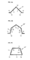
- the structural material may have any shape as long as at least one bent portion which extends in one direction thereof (for example, longitudinal direction) and has a bend in a direction perpendicular to the extending direction is provided, and for example, may have cross-sectional shapes as illustrated in FIGS. 4A to 4C .
- a structural material 10' includes four flat portions 11 and three bent portions 12 provided between the flat portions 11, and the flat portions 11 positioned at both ends in the cross-sectional shape thereof function as flanges for joining the structural material 10' to a structural material (not shown) having a different flat sheet shape.
- a structural material 10" includes five flat portions 11 and four bent portions 12 provided between the flat portions 11, and the flat portions 11 positioned at both ends in the cross-sectional shape thereof function as flanges for joining the structural material 10" to a structural material (not shown) having a different flat sheet shape.
- a structural material 10'" includes four flat portions 11 and four bent portions 12 provided between the flat portions 11 so as to have a quadrangular cross-section.
- the structural material 10 may not extend linearly in the longitudinal direction, and for example, may be curved or bent as illustrated in FIG. 5 .
- the direction along the curving and bending is referred to as the longitudinal direction. Therefore, in the example illustrated in FIG. 5 , the dot-dashed line Z in the figure represents the longitudinal direction of the structural material 10.
- the flat portion means a part of the structural material of which the cross-section has a linear shape (band shape).
- the bent portion means a part of the structural material having a line shape formed by intersection in the extending directions of two flat portions adjacent to each other in the cross-section of the structural material. Therefore, like flat portions 11 a to 11e and bent portions 12a to 12d illustrated in FIG. 5 , cases where flat portions and bent portions are curved or bent in the longitudinal direction of a structural material are respectively included in flat portions and bent portions.
- a heat treatment (here, a laser heat treatment as an example) is performed on a specific site of the untreated structural material 10 formed in the shape as described above.
- a laser heat treatment device using a carbon dioxide laser, a YAG laser, a fiber laser, or the like is used.
- the area is hardened into a depth of 10% or more of the sheet thickness from the surface irradiated with a laser light.
- the depth in the sheet thickness direction of the area to be hardened by the laser heat treatment be controlled to be less than 90% of the sheet thickness from the surface irradiated with the laser light.
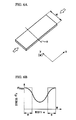
- the same stress as the stress ⁇ max exerted on the end portions in the width direction of the thin sheet is uniformly distributed in the virtual parts having widths 2xe as shown by the broken lines of FIG. 6B and the virtual parts having the widths 2xe receive the total load.
- the width e is called an effective width, and the effective width e is defined by the following Expression (14), that is, Expression (15).
- the effective width e is expressed by the following Expression (16) using the elastic modulus E, the Poisson's ratio v, and the thickness t of the thin sheet, and in particular, the effective width e may be expressed by Expression (17) when the yield stress ⁇ Y0 of the thin sheet is uniformly distributed.
- the effective width e expressed by the above Expressions (16) and (17) are theoretical values, and it is demonstrated that when the theoretical values are used, experimental results are significantly different from the yield phenomenon depending on the conditions. Therefore, in consideration of the theoretical results, the effective width e is defined by, for example, the following Expressions (18A) and (19).
- ⁇ is a slenderness factor and is determined as in Expression (20) in the case where the yield stress ⁇ Y0 of the thin sheet is uniformly distributed in the parts having the effective width e.
- k means a flat sheet buckling coefficient.
- the definition of the effective width e as in the following Expression (18B), there are various definitions besides the above Expression (18A).
- any definition from among the various definitions may be used.
- a stress distribution in the width direction of the thin sheet when the thin sheet buckles under the compressive load that is, the stress distribution as shown in FIG. 6B
- a numerical analysis for example, a numerical integral such as the finite element method
- the effective width e that satisfies the above Expression (14) may be calculated.
- the area in each of the flat portions 11 that mainly receives the compressive load is an area of which the distance in the width direction from the bent portion 12 (that is, a direction perpendicular to the longitudinal direction of the structural material 10) is within the effective width e.
- an area that is, the area having a bent portion of which the distance in the width direction from a certain bent portion is within the effective width e is referred to as an effective width area.
- the effective width areas (effective width areas 15 in FIGS. 2 and 3 ) are shown by oblique lines in FIG. 2 and the entirety thereof is shaded in FIG. 3 .
- the effective width of an untreated structural material having at least one bent portion as illustrated as the bent portions 12 (12a to 12d) of FIG. 3 (bent portions of a structural material) is determined.
- a heat treatment (here, a laser heat treatment as an example) is performed on a part of the effective width area determined as described above.
- a heat treatment here, a laser heat treatment as an example
- the ratio of the area on which the laser heat treatment to the effective width area is performed will be described.
- FIG. 7 shows a true stress-true plastic strain curve of a steel sheet in a grade of a tensile strength of 440 MPa.
- the work-hardening coefficient E h is expressed by the following Expression (21).
- ⁇ p represents strain after the steel sheet yields (plastic strain)
- ⁇ h represents stress when the plastic strain is ⁇ p .
- ⁇ h is described as a stress when the plastic strain ⁇ p is 1%.
- ⁇ h may be determined from the stress when the plastic strain ⁇ p is 1%.
- Expression (22) represents the elastic-plastic buckling stress ⁇ p,Cr in a steel sheet as illustrated in FIG. 6A and does not represent the elastic-plastic buckling stress ⁇ p,Cr regarding a structural material having a polygonal cross-section as illustrated in FIG. 3 .
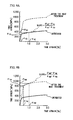
- FIG. 8 shows true stress-true strain curves of an untreated steel sheet in a grade of a tensile strength of 440 MPa and the material of a steel sheet in a grade of a tensile strength of 440 MPa of which the entirety is subjected to a heat treatment (is quenched).
- the solid line of FIG. 8 represents the true stress-true strain curve of the untreated steel sheet, and the broken line represents the true stress-true strain curve of the steel sheet after the heat treatment.
- the work-hardening coefficient of the untreated steel sheet E h0 can be expressed by the following Expression (24) (see FIG. 9A ).
- Expression (24) ⁇ Y0 represents the yield stress of the untreated steel sheet, ⁇ Y0 represents the true strain of the untreated steel sheet at the yield stress, ⁇ h0 represents a predetermined true strain greater than ⁇ Y0 , and ⁇ h0 represents the stress (corresponding to a flow stress described later) of the untreated steel sheet when the true strain is ⁇ h0 .
- the work-hardening coefficient of the steel sheet after the heat treatment E hM can be expressed by the following Expression (25) (see FIG. 9B ).
- ⁇ YM represents the yield stress of the steel sheet after the heat treatment
- ⁇ YM represents the true strain of the steel sheet after the heat treatment at the yield stress
- ⁇ hM represents a predetermined true strain greater than ⁇ YM
- ⁇ hM represents the stress (corresponding to a flow stress described later) of the steel sheet after the heat treatment when the true strain is ⁇ hM .
- the work-hardening coefficient of the steel sheet after the heat treatment E hM is greater than the work-hardening coefficient of the steel sheet before the heat treatment E h0 . Therefore, in the case where the heat treatment is performed on the entire steel sheet, the steel sheet after the heat treatment has a greater initial peak stress ⁇ 1 than that of the steel sheet before the heat treatment.
- the steel sheet of which the entirety is subjected to the heat treatment has a greater initial peak stress ⁇ 1 .
- the relationship between the ratio at which the heat treatment is performed on the steel sheet, that is, the ratio of an area which is hardened to a predetermined or higher hardness by the heat treatment (hereinafter, referred to as a hardened area) to the entire steel sheet and the initial peak stress is found to be unclear.
- the inventors obtained the following knowledge as a result of examining the relationship between the volume fraction f M the work-hardening coefficient E h of the steel sheet after the partial hardening, and the initial peak stress ⁇ 1 when the volume fraction of the hardened area (hardening ratio) f M with respect to the entire steel sheet is changed from 0 to 100%.
- the obtained knowledge will be described in detail.
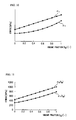
- the proof stress ⁇ h of the steel sheet when 5% of plastic strain occurs may be approximated by a substantially straight line with respect to the volume fraction f M . This is because when a certain degree of limited plastic strain is given to the entire steel sheet, substantially the same plastic strain is exerted on both the hardened area and the non-hardened area (an area of the steel sheet other than the hardened area, that is, an untreated area).
- the proof stress ⁇ h after giving 5% of plastic strain with respect to the volume fraction of the hardened area f M is expressed by the following Expression (26) as a function of the volume fraction f M .
- the proof stress ⁇ h of the steel sheet is proportionate to the volume fraction of the hardened area f M (the amount of change of the rate of change in the flow stress with respect to the hardening ratio is substantially 0) is performed, the relationship between the proof stress ⁇ h of the steel sheet and the volume fraction of the hardened area f M can be sufficiently and accurately expressed.
- the yield stress ⁇ Y is more accurately expressed using the volume fraction of the hardened area f M .
- the volume fraction of the hardened area f M is small, the characteristics of the non-hardened area having a relatively small yield stress becomes dominant in the yield phenomenon, and the entire yield stress becomes close to the yield stress of the non-hardened area (see Expression (27)).
- the volume fraction of the hardened area f M increases by a certain degree, the influence of the characteristics of the hardened area increases when the yield phenomenon occurs. In particular, when the volume fraction of the hardened area f M becomes 1, the entire yield stress becomes equal to the yield stress of the hardened area (see Expression (28)).
- the yield stress ⁇ Y ( ⁇ Y (f M )) can be expressed by the following Expression (29) as a function of the volume fraction f M .
- Expression (29) a, b, and c are constants.
- the constant b of the above Expression (29) can be represented by the following Expression (30). That is, the constant b can be approximated by the gradient of the change in the yield stress ⁇ Y (f M ) with respect to the volume fraction f M when the volume fraction of the hardened area f M is 0.
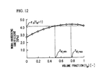
- the work-hardening coefficient E h (f M ) can also be expressed as a quadratic function (a convex upward function of the volume fraction f M in a range of 0 to 1) of the volume fraction of the hardened area f M . Accordingly, as can be seen from FIG. 12 , the work-hardening coefficient E h (f M ) is maximized at a specific volume fraction f M-max .
- the work-hardening coefficient E h (f M ) is higher than the work-hardening coefficient which is when the volume fraction of the hardened area f M is 1 (100%) depending on the volume fraction of the hardened area f M .
- the initial peak stress when the volume fraction of the hardened area f M is f M-min to 1 becomes higher than or equal to the initial peak stress which is when the volume fraction of the hardened area f M is 1 (100%) (that is, when the heat treatment is performed on the entire effective width).
- the laser heat treatment is used as the heat treatment for locally hardening a part of the steel sheet.
- the amount of energy consumed increases as the treatment area increases, resulting in an increase in manufacturing cost. Accordingly, in terms of a reduction in manufacturing cost, it is preferable that an area on which the laser heat treatment be as narrow as possible.
- the initial peak stress can be increased to be higher than or equal to the initial peak stress which is when the volume fraction of the hardened area f M is 1 (100%).
- the minimum volume fraction f M-min is expressed by the following Expression (32).
- the minimum volume fraction f M-min is 53.3%.
- the constants b and ⁇ h also need to satisfy 0 ⁇ b ⁇ 2 ⁇ Y - ⁇ h and ⁇ Y ⁇ h ⁇ 2 ⁇ Y .
- the work-hardening coefficient E h (f M ), that is, the initial peak stress is maximized at a specific volume fraction f M-max . Accordingly, in terms of increasing the initial peak stress while narrowing the area on which the laser heat treatment is performed, it is preferable that the volume fraction of the hardened area f M be controlled to be less than or equal to the volume fraction f M-max which is when the work-hardening coefficient E h (f M ) is maximized.
- the volume fraction of the hardened area f M be controlled to be the volume fraction f M-max which is when the work-hardening coefficient E h (f M ) is maximized. Therefore, the volume fraction of the hardened area f M may be controlled to be the volume fraction f M-max (hereinafter, referred to as "maximum volume fraction") which is when the work-hardening coefficient E h (f M ) is maximized.
- the maximum volume fraction f M-max is expressed by the following Expression (33).
- the maximum volume fraction f M-max is 76.6%.
- the constants b and ⁇ h also need to satisfy 0 ⁇ b ⁇ h and 0 ⁇ b ⁇ Y .
- the relationship between the volume fraction of the hardened area f M described above and the initial peak stress or the work-hardening coefficient E h is a relationship obtained for a steel sheet, and is not a relation obtained for, for example, the structural material 10 having the shape as illustrated in FIG. 2 .
- areas that mainly receive the compressive load is the effective width areas 15, and the effective width areas 15 can be assumed to be a steel sheet having a width of 2xe. Therefore, the volume fraction of the hardened area f M in such an effective width area, that is, the ratio of an area in the effective width area on which a hardening treatment (for example, a laser heat treatment) is performed can be set by the method as described above.
- the laser heat treatment is performed so that the volume fraction of the hardened area f M in each of the effective width areas 15 becomes higher than or equal to f M-min expressed by Expression (32) and less than or equal to f M-max expressed by Expression (33).
- ⁇ hM , ⁇ h0 , ⁇ YM , and ⁇ Y0 are parameters regarding the
- the initial peak stress of the structural material 10 can be increased while causing the area on which the laser heat treatment is performed to be small.
- the volume fraction of the hardened area f M in each of the effective width areas 15 is controlled to be higher than or equal to f M-min and less than or equal to f M-max .
- the volume fraction of the hardened area f M may also be controlled to be higher than or equal to f M-min and less than or equal to 1 (100%) or less than 1.
- it may be determined that the volume fraction of the hardened area f M in each of the effective width areas 15 is set so that the work-hardening coefficient E h of each of the effective width areas 15 becomes equal to or higher than the work-hardening coefficient which is when the entire area of the effective width areas 15 is hardened by the laser heat treatment.
- the volume fraction of the hardened area f M in each of the effective width areas 15 may also be controlled to be f M-max .
- the minimum value of the volume fraction f M is determined on the basis of the rate of change of the yield stress ⁇ Y with respect to the volume fraction f M in the case where the volume fraction of the hardened area f M is 0, the rate of change (constant) is called b (S311), and the maximum value of the range of the volume fraction f M is determined to be less than or equal to 1 or less than 1 (S312), thereby the range of the volume fraction of the hardened area f M may be determined.
- the maximum value of the range of the volume fraction f M may also be determined on the basis of the rate of change of the yield stress ⁇ Y with respect to the volume fraction f M in the case where the volume fraction of the hardened area f M is 0, the rate of change (constant) is called b (S313).
- a method of determining the constant b for determining the range of the volume fraction of the hardened area f M described above will be described.
- a tensile test is performed on three specimens of which the volume factions f M of the hardened areas of steel sheets are 0, 1, and an arbitrary value that is higher than 0 and less than 1 (for example, 0.5), the yield stresses ⁇ Y of the specimens are obtained, and the method of least squares is performed thereon, thereby the constants a, b, and c can be determined.
- a tensile test is performed on two specimens of which the volume factions f M of the hardened areas of steel sheets are 0, and an arbitrary value that is higher than 0 and close enough to 0 (for example, 0.1), the yield stresses ⁇ Y of the specimens are obtained, and the constant b can be determined as the rate of increase in the yield stress ⁇ Y with respect to the volume faction of the hardened area f M .
- the method of determining the constant b using the minimum number of pieces of data needed (the number of pieces of data of the yield stresses ⁇ Y ) as a simple method has been described.
- the upper limit of the number of pieces of data is not particularly limited. As the number of pieces of data increases, the range of the volume fraction f M can be determined with higher precision.
- the yield stress ⁇ Y and the proof stress ⁇ h can be measured by performing a tensile test according to JIS Z2241 on JIS No. 5 specimens (specimens) sampled from a steel sheet (no heat treatment and bending process) used as structural material.
- specimens obtained by performing a predetermined heat treatment on the above specimens may be used.
- the specimens may be heated to the A e3 point (A e3 temperature) or higher, and thereafter may be cooled to the M s point (M s temperature) or less at a cooling rate of higher than or equal to 10 °C/s, and preferably higher than or equal to 30 °C/s by cooling means such as water cooling and/or air cooling.
- the tensile test described above may be performed on the above specimens which is performed a laser heat treatment in the longitudinal direction under the conditions corresponding to the abovementioned predetermined heat treatment.
- the correspondence relationship between the volume fraction f M , the yield stress ⁇ YM , and the proof stress ⁇ hM may be determined.
- the laser heat treatment (1 pass) may be repeatedly performed on one surface or both surfaces of the specimens in the longitudinal direction of the specimens while displacing the positions of the specimens in the width direction (a direction perpendicular to the longitudinal direction).
- specimens on which a strain history corresponding to the bend-processed portion (bent portion) of the structural material before the heat treatment is applied may also be used.
- the volume fraction of the hardened area f M can be determined by a method as follows. For example, the area of the hardened area in a cross-section perpendicular to the longitudinal direction of the specimen is measured, and the volume of the hardened area is obtained by multiplying the area by a length (total length) on which the laser heat treatment is performed, and the volume of the hardened area is divided by the total volume of the specimen, thereby the volume fraction of the hardened area f M can be obtained.
- the area of the hardened area may be determined from a quenched structure observed with an optical microscope from the cross-section perpendicular to the longitudinal direction of the specimen, and may also be determined by obtaining the Vickers hardness using a Vickers hardness tester as described later.
- the relationship between the proof stress ⁇ h of the steel sheet and the volume fraction of the hardened area f M is expressed by a linear function
- the relationship between the yield stress ⁇ Y of the steel sheet and the volume fraction of the hardened area f M is expressed by a quadratic function.
- such functions may not be necessarily used.
- the fact that the rate of change in the yield stress with respect to the volume fraction of the hardened area f M varies depending on the volume fraction of the hardened area f M and the amount of change (a degree of change) is greater than the amount of change (a degree of change) of the rate of change in flow stress with respect to the volume fraction of the hardened area f M may be used.
- the relationship between the yield stress ⁇ Y of the steel sheet and the volume fraction of the hardened area f M may be expressed by an arbitrary function ⁇ Y (f M ), and the range of the volume fraction of the hardened area f M may be determined using the rate of change in the yield stress (in a case of a quadratic function, corresponding to the constant b) with respect to at least one hardening ratio.
- the quadratic function is extended to a general function
- the minimum volume fraction f M-min (other than 1) and the maximum volume fraction f M-max may be determined to satisfy the following Expressions (34) and (35).
- ⁇ Y (f M ) can be expressed as a function including the constant b described above.
- the relationship between the proof stress ⁇ h of the steel sheet and the volume fraction of the hardened area f M may be expressed by an arbitrary function ⁇ h (f M ).
- the maximum volume fraction f M-max can be determined to satisfy the following Expression (36).
- the range of the volume fraction of the hardened area f M may be determined within the range of any of the following Expressions (37) to (40).
- the work-hardening coefficient E h (the relationship between the volume fraction f M and the work-hardening coefficient E h ) is estimated or calculated on the basis of the range of change in the yield stress ⁇ Y with respect to the volume fraction of the hardened area f M (S301), and the range of the volume fraction f M may be determined so that the estimated or calculated work-hardening coefficient E h becomes higher than or equal to a predetermined value (S302).
- the difference between the work-hardening coefficient E h in the case where the volume fraction f M is 1 and the work-hardening coefficient E h in the case where the volume fraction f M is f M-max is defined as ⁇ E h
- an arbitrary value that is higher than or equal to 0 and less than or equal to 1 is defined as an improvement coefficient n
- a value obtained by adding n ⁇ h to the work-hardening coefficient E h in the case where the volume fraction f M is 1 may be determined as a predetermined value. Therefore, the predetermined value may be the work-hardening coefficient E h in the case where the volume fraction of the hardened area f M is 1.
- a different index of work-hardening including the yield stress ⁇ Y as at least a variable may also be used.
- the range of the volume fraction of the hardened area f M can be determined most simply.
- the range of the volume fraction of the hardened area f M can be determined using the constant a instead of the constant b.
- the constant a can be expressed using the constant b (the constant a is a dependent variable of the constant b), and thus it is assumed that the use of the constant a is the same as the use of the constant b.
- the range of the volume fraction f M can be determined on the basis of the volume fraction f M which is when the rate of change in the yield stress ⁇ Y with respect to the volume fraction of the hardened area f M satisfies a predetermined condition. For example, upon considering that the work-hardening coefficient E h draws a convex downward curve with respect to the volume fraction of the hardened area f M , the volume fraction f M which is when the first order differential of the work-hardening coefficient E h expressed by the above Expression (21) with respect to volume fraction f M becomes 0, that is, the volume fraction (boundary hardening ratio) f M that satisfies the above Expression (36) may be determined as the maximum volume fraction f M-max .
- the range of the volume fraction of the hardened area f M can be determined as, for example, a range that satisfies the above Expressions (37) to (41).
- the minimum volume fraction f M-min (other than 1) can be determined using the above Expression (34).
- ⁇ E h described above is determined from the minimum volume fraction f M-min and the maximum volume fraction f M-max determined by Expressions (34) and (36), and the range of the volume fraction f M may be determined using the improvement coefficient n described above so that the work-hardening coefficient E h is higher than or equal to a value obtained by adding n ⁇ E h to the work-hardening coefficient E h in the case where the volume fraction f M is 1. That is, as shown in FIG.
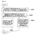
- the maximum volume fraction f M-max of the volume fraction f M is determined on the basis of the rate of change in the yield stress ⁇ Y with respect to the volume fraction of the hardened area f M (S321), the minimum value of the range of the volume fraction f M is determined as a value smaller than the maximum volume fraction f M-max by a predetermined value (S322), and the maximum value of the range of the volume fraction f M may be determined to be less than or equal to 1 or less than 1 (S323).
- the maximum value of the range of the volume fraction f M may be determined to be a value greater than the maximum volume fraction f M-max by a predetermined value (S324).
- the same function for example, a linear function such as a quadratic function
- this range may be divided into a plurality of ranges and the different functions may also be used for each ranges.
- the change in the rate of change in the yield stress ⁇ Y with respect to the volume fraction f M is used, in the case where the same function is used in the range in which the volume fraction is 0 to 1, the function in this range needs to be able to differentiated twice with respect to the volume fraction f M .
- an interpolation function including a case where the interpolation function is linear (a graph of broken line)
- various interpolation methods for example, spline interpolation
- actual measurement data for example, 5 or more points
- the same function for example, a linear function such as a linear function
- this range may be divided into a plurality of ranges and different functions may also be used for each ranges.
- the relationship between the proof stress ⁇ h of the steel sheet and the volume fraction of the hardened area f M be expressed by a linear function and the relationship between the yield stress ⁇ Y of the steel sheet and the volume fraction of the hardened area f M be expressed by a quadratic function.
- ⁇ h (f M ) is defined as the proof stress which is when 5% of plastic strain occurs.
- the plastic strain corresponding to the proof stress may not be necessarily limited to 5% and may not be 5% as long as it is greater than 0%.
- ⁇ h (f M ) can also be defined as a proof stress which is when 1% of plastic strain occurs.
- a proof stress which is when a predetermined plastic strain occurs (or a stress needed to cause plastic deformation from a state where a predetermined plastic strain occurs) is defined as a flow stress
- ⁇ h (f M ) represents the flow stress
- ⁇ hM represents the flow stress of the hardened area
- ⁇ h0 represents the flow stress of the non-hardened area (untreated structural material).
- the flow stress may be a stress at a stain amount determined in a range which is greater than a strain amount (that is, the plastic strain is greater than 0) corresponding to the yield stress and smaller than a uniform elongation strain amount (for example, the maximum amount of nominal strain).
- the structural material 10 is locally heated and hardened by the laser heat treatment.
- local hardening of the structural material 10 may not necessarily be performed by the laser heat treatment and may also be performed by another heat treatment.
- the hardness of the area hardened by the heat treatment be higher than or equal to the reference hardness (Vickers hardness) Hv calculated by the following Expressions (45) and (46) when the carbon content of the structural material 10 which is a steel material is defined as C, the silicon content is defined as Si, the manganese content is defined as Mn, the nickel content is defined as Ni, the chromium content is defined as Cr, the molybdenum content is defined as Mo, the niobium content is defined as Nb, the vanadium content is defined as V.
- the laser heat treatment is performed on the effective width areas 15 in the peripheries of the two bent portions 12b and 12c and the laser heat treatment is not performed on the effective width areas 15 in the peripheries of the two different bent portions 12a and 12d.
- the laser heat treatment may also be performed on the effective width areas in the peripheries of the two different bent portions, or the laser treatment may be performed only on the effective width area 15 in the periphery of one bent portion of the two bent portions 12b and 12c.
- the heat treatment may be performed on the effective width area including at least one bent portion at a volume fraction f M as described above.
- the heat-treated structural material according to this embodiment includes, as in the above embodiment, at least one bent portion which extends in one direction of the structural material and has a bend in a direction perpendicular to the one direction. Therefore, the heat-treated structural material according to this embodiment includes, for example, structural materials having shapes as illustrated in FIGS. 2 to 5 . Moreover, the volume fraction f M of the above-described hardened area with respect to the above-described effective width areas is less than 1 and is included in the range of the volume fraction f M determined on the basis of the rate of change in the yield stress ⁇ Y with respect to the volume fraction f M .
- the heat-treated structural material according to this embodiment may exhibit a higher ability to suppress deformation than that according to the conventional technique while maintaining costs as low as possible.
- the range of the volume fraction of the hardened area f M can be determined on the basis of the rate of change in the yield stress ⁇ Y with respect to the volume fraction f M in the case where the value of the volume fraction f M is 0 as described above.
- the range of the volume fraction f M is a range determined so that the work-hardening coefficient E h calculated on the basis of the rate of change in the yield stress ⁇ Y with respect to the volume fraction f M is higher than or equal to a predetermined value.
- the predetermined value is preferably the value of the work-hardening coefficient E h in the case where the volume fraction f M is 1, and more preferably a value greater than the work-hardening coefficient E h in the case where the volume fraction f M is 1.
- the range (lower limit) of the volume fraction of the hardened area f M be higher than or equal to the minimum volume fraction f M-min expressed by the above Expression (32).
- the range (upper limit) of the volume fraction of the hardened area f M be lower than or equal to the maximum volume fraction f M-max expressed by the above Expression (33).
- the flow stress may be defined as a proof stress which is when 5% of plastic strain occurs.
- the effective width e may be defined by the above Expressions (15), (17), and (18B) or the following Expression (47).
- the finite element method may be used.
- Expression (47) is derived from the above Expressions (18A) to (20) assuming that the flat sheet buckling coefficient is 4.
- the hardened area (the area hardened by the heat treatment) may be obtained by the same method as that of the embodiment. That is, the hardened area can be determined to be an area that has a hardness of higher than or equal to the Vickers hardness calculated by above Expressions (45) and (46).
- the heat treatment be performed using a laser. The history of the heat treatment using the laser may be checked by observing the structure of the cross-section of the structural material.
- a carbon dioxide laser was used, a laser output was controlled to 5 kW, and a heat treatment speed was controlled to 12 m/min. Moreover, a tensile test was performed on the 11 specimens to evaluate yield stresses and tensile stresses.
- the yield stress of the non-hardened area ⁇ Y0 was determined as 301 MPa
- the proof stress ⁇ h0 of the non-hardened area when a plastic strain ⁇ p of 0.05 (0.0537) was given was determined as 447 MPa.
- the yield stress of the hardened area ⁇ YM was determined as 794 MPa
- the proof stress ⁇ hM of the hardened area when a plastic strain ⁇ p of 0.05 (0.0537) was given was determined as 1017 MPa.
- the yield stresses obtained from the 11 specimens were plotted with respect to the volume fractions, and the method of least squares using the above Expression (29) as a regression equation was applied to the plot, thereby determining the constant b as 350 MPa.
- the method of least squares was performed on the three plots of the yield stress of the untreated specimen, the specimen having a volume fraction of 0.5 (50%), and the specimen having a volume fraction of 1 (100%), the same constant b was obtained.
- the effective width e was 19.2 mm.
- the flat sheet buckling coefficient k which is a coefficient in response to the sheet shape or the like was 4
- the sheet width w was 60 mm
- the sheet thickness t was 1.0 mm
- the yield stress ⁇ Y0 was 301 MPa
- the elastic modulus E was 180 GPa.
- the average value (60 mm) of the height (50 mm) illustrated in FIG. 14 and the width (70 mm) of the top portion was used as a representative value.
- the steel sheet BP ( FIG. 13A ) was subjected to a bending process, thereby manufacturing an untreated structural material 10 having a shape as illustrated in FIG. 13B .
- the untreated structural material 10 includes five flat portions which are arranged so that the cross-section thereof has a hat shape as illustrated in FIG. 14 .
- the lengths of sides in the vertical cross-section of the sides including the three flat portions 11 at the center were 50 mm, 70 mm, and 50 mm, respectively.
- the untreated structural material 10 manufactured as such was spot-welded to a different structural material 20 having a flat sheet shape, thereby manufacturing a structural material assembly as illustrated in FIG. 13 .
- Spot welding S was performed on the center in the width direction of the flat portions constituting flange portions at an interval of 30 mm in the longitudinal direction.
- the distance from the end portion in the longitudinal direction (the end portion on a side on which an impact is inserted, hereinafter, referred to as "impact exertion side end portion") to the initial spot weld was 15 mm.
- the laser heat treatment was performed in a plurality of passes in the longitudinal direction (tensile direction) of the specimens using the carbon dioxide laser.
- the laser output was controlled to 5 kW, and the heat treatment speed was controlled to 12 m/min.
- the laser output and the heat treatment speed in the laser heat treatment were controlled in the same manner in the following examples.
- the laser heat treatment was performed over the entirety of an area of 19.2 mm from the bent portion shaded in black in FIG. 14 , that is, over the entirety of the effective width area. Therefore, in this case, the volume fraction of the hardened area with respect to the effective width area was 100%.
- the structural material assembly was installed so that the longitudinal direction of the structural material assembly on which the laser heat treatment was performed as such was aligned with the vertical direction and the impact exertion side end portion thereof has an upward trend, and an impact test was performed by falling a falling weight of 300 kg positioned immediately thereon from a height of 2 m.
- an impact test was performed on the structural material assembly on which the laser heat treatment was performed as such, and an initial peak reaction force and an initial peak stress were calculated on the basis of the test results.
- the initial peak reaction force at this time was 150.6 kN, and the initial peak stress was 443.0 MPa.
- substantially the same ability to suppress deformation to that of the test No. 1 can be obtained at lower cost than that of the test No. 1.
- a higher ability to suppress deformation than that of the test No. 1 can be obtained at lower cost than that of the test No. 1.
- the structural material By performing a heat treatment on appropriate spots of an untreated structural material to locally harden the structural material, the structural material having a sufficiently high ability to suppress deformation can be provided.
Landscapes
- Chemical & Material Sciences (AREA)
- Engineering & Computer Science (AREA)
- Mechanical Engineering (AREA)
- Materials Engineering (AREA)
- Metallurgy (AREA)
- Organic Chemistry (AREA)
- Physics & Mathematics (AREA)
- Thermal Sciences (AREA)
- Crystallography & Structural Chemistry (AREA)
- Heat Treatment Of Articles (AREA)
- Body Structure For Vehicles (AREA)
Abstract
Description
- The present invention relates to a heat treatment method of a structural material and a heat-treated structural material.
Priority is claimed on Japanese Patent Application No.2010-190741, filed August 27, 2010 - As structural materials of a vehicle and the like, pipe-like press-formed products having polygonal cross-sections have been widely used. Such structural materials are mainly classified into two categories for use. In one category, there are structures that are used to construct, for example, an engine compartment or a trunk compartment and are structures which operate to be crushed when a vehicle or the like crashes and absorb impact energy. In the other category, there are structures that are used to construct, for example, a cabin and the like and are structures of which deformation is suppressed in terms of ensuring a survival space of an occupant when a vehicle or the like crashes.
- In such structural materials, in order to both absorb impact energy and suppress deformation during the crash, it is necessary to increase the strength of the structural material, and there is a method of increasing the cross-sectional dimensions and the thickness of the structural material. However, this case is connected to an increase in the volume or the weight of the structural material. Therefore, not only a decrease in fuel efficiency but also an increase in damage to a counter vehicle during the crash of vehicles is caused.
- On the other hand, as a method of increasing the strength of the structural material without increasing the cross-sectional dimensions or the thickness of the structural material, various methods of partially performing a laser heat treatment on a structural material such as a press-formed product have been proposed (for example,
Patent Citations 1 to 4). Here, the laser heat treatment refers to irradiating an untreated structural material with a laser beam with a high energy density to locally heat the structural material to a temperature higher than or equal to a transformation temperature or a melting point, and causing the structural material to be subjected to quench hardening by a self-cooling operation. - For example, in Patent Citation 1, a method of performing a local heat treatment on a press-formed product by a laser to achieve an increase in the strength of the press-formed product is disclosed. Specifically, in Patent
Citation 1, after cold-forming a steel sheet, the steel sheet is rapidly heated at a temperature of higher than or equal to a predetermined temperature with a laser beam in a streak shape or a grid form and is thereafter cooled, thereby strengthening the cold-formed press-formed product. By employing such a method, the generation of strain after the heat treatment is suppressed compared to a case where the entire press-formed product is uniformly heat-treated. Particularly, in the method disclosed in Patent Citation 1, a laser heat treatment is performed on the outer surface of a press-formed product in a streak shape in the longitudinal direction or on the entire outer surface of a press-formed product in a grid form. - In addition, even in the method disclosed in Patent Citation 2, performing a local heat treatment on a press-formed product for the purpose of increasing the strength of the press-formed body while suppressing the generation of strain is disclosed. Particularly, in the method disclosed in Patent Citation 2, a site of the press-formed product which requires strength, for example, a high stress portion analyzed by, for example, a vehicle crash test or a finite element method is subjected to the heat treatment. Specifically, a laser heat treatment is performed in a stripe shape or a grid form so as to extend over the entire length in the longitudinal direction of the press-formed product.
- Moreover, in
Patent Citation 3, a method of controlling components contained in a steel sheet to be subjected to a laser heat treatment to specific components and then performing the laser heat treatment thereon is disclosed, and accordingly the strength of spots subjected to the laser heat treatment is enhanced while maintaining the workability of the steel sheet. Even in the method disclosed in Patent Citation 3, spots of which the strength needs to be increased are subjected to the laser heat treatment. Specifically, the laser heat treatment is performed in a linear form extending over the entire length in the longitudinal direction of the press-formed product. - In Patent Citation 4, for the purpose of enhancing the ability to absorb the impact energy of the press-formed product, a method of performing a laser heat treatment in a line form along the load direction of a compressive load on the outer peripheral surface of the press-formed product is disclosed. According to this method, since the laser heat treatment is performed in the same direction as the input direction of an impact load, a resistance against deformation can be increased, and a regular crushing mode may be achieved. Particularly, in the method disclosed in Patent Citation 4, the laser heat treatment is continuously performed over the entire length in the longitudinal direction of the press-formed product along the load direction of the compressive load.
- In any case, in any of the methods disclosed in
Patent Citations 1 to 4, a laser heat treatment is performed on a part of the outer surface of the press-formed product, which requires strength. Specifically, the laser heat treatment is performed in the line form that continuously extends over the entire length in the longitudinal direction of the press-formed product, or the laser heat treatment is performed in the grid form over the entire outer surface of the press-formed product. -
- [Patent Citation 1] Japanese Unexamined Patent Application, First Publication No.
S61-99629 - [Patent Citation 2] Japanese Unexamined Patent Application, First Publication No.
H4-72010 - [Patent Citation 3] Japanese Unexamined Patent Application, First Publication No.
H6-73439 - [Patent Citation 4] Japanese Unexamined Patent Application, First Publication No.
2004-108541 -
FIG. 1 schematically illustrates the relationship between, when a cylindrical structural material receives a compressive load in the axial line direction (x direction) thereof, the compressive stress in the axial line direction σx and the compressive strain εx (the amount of deformation in the longitudinal direction with respect to the length in the longitudinal direction of the cylindrical structural material). Here, σ1, σ2, and σ3 in the figure represent peak stresses, and an area shown by oblique lines W represents the amount of energy absorbed by the structural material. Particularly, σ1 represents the initial peak stress. - Here, as the structural materials used in a vehicle and the like as described above, there are structural materials that absorb impact energy during a crash (hereinafter, referred to as "structural materials for impact absorption") and structural materials that suppress the deformation thereof during a crash (hereinafter, referred to as structural materials for deformation suppression). The structural materials for impact absorption thereof require as high as possible an absorption energy amount W and require a relatively low initial peak stress σ1.
- On the other hand, the structural materials for deformation suppression require as high as possible an initial peak stress σ1 unlike the structural materials for impact absorption. This is because when the initial peak stress σ1 is increased, it is difficult for the structural materials to buckle even though a high stress is applied to the structural material. Therefore, it is necessary to perform a laser heat treatment on the structural materials for deformation suppression so as to increase the initial peak stress σ1.
- However, in the methods disclosed in
Patent Citations 1 to 4 described above, since the laser heat treatment is performed with no consideration of the initial peak stress σ1 at all, and thus it is difficult to say that the ability of the structural material to suppress deformation can be sufficiently increased. - In consideration of the problems, an object of the present invention is to provide a structural material which can sufficiently increase an ability to suppress deformation by performing a heat treatment on appropriate spots of an untreated structural material and thus locally hardening the structural material.
- The inventors have examined, regarding a structural material having at least one bent portion which extends in one direction (for example, longitudinal direction), the relationship between an area (spot or amount) of an untreated structural material on which a heat treatment is performed, and an ability of a structural material after the heat treatment to suppress deformation, particularly, an initial peak stress.
- As a result, it was found that by appropriately controlling the ratio of a hardened area that is hardened by the heat treatment in an effective width area of which the distance in the width direction from each bent portion is within an effective width, the ability of the structural material to suppress deformation, particularly the initial peak stress may be enhanced.
- The invention has been made on the basis of the knowledge, and the gist thereof is as follows.
- (1) A heat treatment method of a structural material according to an aspect of the present invention is a heat treatment method of a structural material which includes a bent portion that extends in one direction of the structural material and has a bend in a direction perpendicular to the one direction, including: determining an effective width of the bent portion e; defining an effective area as an area which includes the bent portion and of which a distance in the direction perpendicular to the one direction from the bent portion is within the effective width, defining a hardening ratio fM as a ratio between an area which is hardened by a heat treatment in the effective width area and the effective area, determining a range of the hardening ratio fM on the basis of a rate of change in a yield stress σY with respect to the hardening ratio fM; and performing the heat treatment on the effective width area of the structural material to satisfy the range of the hardening ratio fM.
-
- (2) In the heat treatment method described in (1), the rate of change may be a value in a case where a value of the hardening ratio fM is 0.
-
- (3) In the heat treatment method described in (2), the range of the hardening ratio fM may be determined so that a work-hardening coefficient Eh calculated on the basis of the rate of change is higher than or equal to a predetermined value.
-
- (4) In the heat treatment method described in (3), the predetermined value may be a work-hardening coefficient Eh in a case where the hardening ratio fM is 1.
-
- (5) In the heat treatment method described in (2), when a difference between a flow stress in a case where the hardening ratio fM is 1 and a flow stress in the case where the hardening ratio fM is 0 is defined as Δσh, a difference between a yield stress in the case where the hardening ratio fM is 1 and a yield stress in the case where the hardening ratio fM is 0 is defined as ΔσY, and the rate of change is defined as b, the range of the hardening ratio fM may be higher than or equal to fM-min expressed by the following Expression (1) and less than 1.
-
- (6) In the heat treatment method described in (5), the range of the hardening ratio fM may be less than or equal to fM-max expressed by the following Expression (2).
[Formula 2]
-
- (7) In the heat treatment method described in (1), a boundary hardening ratio fM at which the rate of change becomes equal to a rate of change in the flow stress σh with respect to the hardening ratio fM may be determined as fM-max, and the range of the hardening ratio fM may be determined on the basis of fM-max.
-
- (8) In the heat treatment method described in (7), the range of the hardening ratio fM may be determined in a range that satisfies the following Expression (3).
-
- (9) In the heat treatment method described in (7), the range of the hardening ratio fM may be determined to be higher than or equal to fM-min that satisfies the following Expression (4) and less than 1.
-
- (10) In the heat treatment method described in (1), when a difference between a flow stress in a case where the hardening ratio fM is 1 and a flow stress in a case where the hardening ratio fM is 0 is defined as Δσh, the range of the hardening ratio fM may be determined so that a difference between Δσh and the rate of change is less than or equal to a predetermined value.
-
- (11) In the heat treatment method described in (1), in a case where, regarding chemical components contained in the structural material, a mass percentage of carbon is defined as C, a mass percentage of silicon is defined as Si, a mass percentage of manganese is defined as Mn, a mass percentage of nickel is defined as Ni, a mass percentage of chromium is defined as Cr, a mass percentage of molybdenum is defined as Mo, a mass percentage of niobium is defined as Nb, and a mass percentage of vanadium is defined as V, the area hardened by the heat treatment may be an area which has a hardness higher than or equal to a Vickers hardness calculated by the following Expressions (5) and (6).
[Formula 5]
[Formula 6]
-
- (12) In the heat treatment method described in (1), the heat treatment may be performed using a laser.
-
- (13) In the heat treatment method described in (1), a pass of the heat treatment may be continuously performed over the entire length of the one direction.
-
- (14) A heat-treated structural material according to another aspect of the present invention includes: a bent portion that extends in one direction of the structural material and has a bend in a direction perpendicular to the one direction, wherein, in a case where an area which includes the bent portion and of which a distance in a direction perpendicular to the one direction from the bent portion is within an effective width e is defined as an effective width area and a ratio of an area which is hardened by a heat treatment in the effective width area is defined as a hardening ratio fM, the hardening ratio fM is less than 1 and is contained in a range of the hardening ratio fM determined on the basis of a rate of change in a yield stress σY with respect to the hardening ratio fM.
-
- (15) In the heat-treated structural material described in (14), the rate of change may be a value in a case where a value of the hardening ratio fM is 0.
-
- (16) In the heat-treated structural material described in (15), the range of the hardening ratio fM may be a range determined so that a work-hardening coefficient Eh calculated on the basis of the rate of change is higher than or equal to a predetermined value.
-
- (17) In the heat-treated structural material described in (16), the predetermined value may be a work-hardening coefficient Eh in a case where the hardening ratio fM is 1.
-
- (18) In the heat-treated structural material described in (14), when a difference between a flow stress in a case where the hardening ratio fM is 1 and a flow stress in a case where the hardening ratio fM is 0 is defined as Δσh, a difference between a yield stress in the case where the hardening ratio fM is 1 and a yield stress in the case where the hardening ratio fM is 0 is defined as ΔσY, and the rate of change is defined as b, the range of the hardening ratio fM may be higher than or equal to fM-min expressed by the following Expression (7).
-
- (19) In the heat-treated structural material described in (18), the range of the hardening ratio fM may be less than or equal to fM-max expressed by the following Expression (8).
-
- (20) In the heat-treated structural material described in (18), each of the flow stresses may be defined as a proof stress which is when 5% of plastic strain occurs.
-
- (21) In the heat-treated structural material described in (19), when a width dimension perpendicular to the one direction is defined as w, a yield stress in the case where the hardening ratio fM is 1 is defined as σY0, and a stress at each position in a width direction perpendicular to the one direction when a stress at which a maximum stress in the one direction of the structural material is σY0 is given in the one direction is defined as σx, the effective width e may be defined by the following Expression (9).
-
- (22) In the heat-treated structural material described in (14), when a thickness dimension is defined as t, a Poisson's ratio is defined as v, an elastic modulus is defined as E, and a yield stress in a case where the hardening ratio fM is 0 is defined as σY0, the effective width e may be defined by the following Expression (10).
-
- (23) In the heat-treated structural material described in (14), when a thickness dimension is defined as t, a width dimension perpendicular to the one direction is defined as w, an elastic modulus is defined as E, and a yield stress in a case where the hardening ratio fM is 0 is defined as σY0, the effective width e may be defined by the following Expression (11).
-
- (24) In the heat-treated structural material described in (14), in a case where, regarding chemical components contained in the structural material, a mass percentage of carbon is defined as C, a mass percentage of silicon is defined as Si, a mass percentage of manganese is defined as Mn, a mass percentage of nickel is defined as Ni, a mass percentage of chromium is defined as Cr, a mass percentage of molybdenum is defined as Mo, a mass percentage of niobium is defined as Nb, and a mass percentage of vanadium is defined as V, the area hardened by the heat treatment may be an area which has a hardness higher than or equal to a Vickers hardness calculated by the following Expressions (12) and (13).
-
- (25) In the heat-treated structural material described in (14), the heat treatment may be performed using a laser.
- According to the present invention, compared to the conventional technique in which a heat treatment is performed on arbitrary spots in an untreated structural material to locally harden the structural material and thus an ability of the structural material to suppress deformation is enhanced, the value of an elastic-plastic buckling stress σp,Cr corresponding to an initial peak stress σ1 of buckling can be obtained, and the volume fraction of a hardened area in an effective width area in which the elastic-plastic buckling stress σp,Cr is maximized can be appropriately determined. Accordingly, in a structural material for deformation suppression, a guideline for appropriate deformation suppression can be provided.
In addition, according to the present invention, the cost of a heat treatment needed to enhance the ability of the structural material to suppress deformation can be optimized (reduced).
In addition, according to the present invention, by measuring the characteristics of a steel material using specimens, the volume fraction of the hardened area in the effective width can be appropriately determined from the characteristics values of the specimens without evaluating a structure. In particular, in the case of (2) described above, the volume fraction of the hardened area in the effective width can be appropriately determined using as low a number of evaluations of the specimens as possible. -
-
FIG. 1 is a diagram schematically illustrating the relationship between, when a cylindrical structural material receives a compressive load in the axial line direction thereof, the compressive stress in the axial line direction and the compressive strain. -
FIG. 2 is a perspective view illustrating an example of a structural material to which a heat treatment method of a structural material according to an embodiment of the present invention is applied. -
FIG. 3 is a transverse sectional view of the structural material illustrated inFIG. 2 . -
FIG. 4A is a transverse sectional view of a structural material of another example. -
FIG. 4B is a transverse sectional view of a structural material of another example. -
FIG. 4C is a transverse sectional view of a structural material of another example. -
FIG. 5 is a perspective view of a structural material of another example. -
FIG. 6A is a diagram for explaining effective widths. -
FIG. 6B is a diagram for explaining effective widths. -
FIG. 7 is a true stress-plastic strain curve of a steel sheet. -
FIG. 8 is a true stress-true strain curve of a steel sheet. -
FIG. 9A is a true stress-true strain curve of a steel sheet. -
FIG. 9B is a true stress-true strain curve of a steel sheet. -
FIG. 10 is a diagram showing the relationship between the volume fraction of a hardened area, the proof stress of a steel sheet, and the yield stress. -
FIG. 11 is a diagram showing the relationship between the volume fraction of a hardened area, the proof stress of a steel sheet, and the yield stress. -
FIG. 12 is a diagram showing the relationship between the volume fraction of a hardened area and a work-hardening coefficient. -
FIG. 13A is a diagram illustrating a manufacturing process of a structural material assembly used in Examples. -
FIG. 13B is a diagram illustrating the manufacturing process of a structural material assembly used in Examples. -
FIG. 13C is a diagram illustrating the manufacturing process of a structural material assembly used in Examples. -
FIG. 14 is a side view of the structural material assembly used in Examples. -
FIG. 15 is a flowchart of the heat treatment method of a structural material according to the embodiment. -
FIG. 16 is a flowchart showing an example of a method of determining the range of the volume fraction of the hardened area (hardening ratio) fM in the heat treatment method of a structural material according to the embodiment. -
FIG. 17 is a flowchart showing an example of the method of determining the range of the volume fraction of the hardened area (hardening ratio) fM in the heat treatment method of a structural material according to the embodiment. -
FIG. 18 is a flowchart showing an example of the method of determining the range of the volume fraction of the hardened area (hardening ratio) fM in the heat treatment method of a structural material according to the embodiment. - Hereinafter, embodiments of the present invention will be described in detail with reference to the drawings. In addition, in the following description, like elements are denoted by like reference symbols.
- Hereinafter, a heat treatment method of a structural material according to an embodiment of the present invention will be described.
In the heat treatment method of a structural material according to this embodiment, a heat treatment is performed on a structural material having a bent portion which extends in one direction of the structural material and has a bend in a direction perpendicular to the extending direction. In the heat treatment, a predetermined ratio (that is, a part corresponding to a hardening ratio) of an area in the structural material, including the bent portion of which the distance in the direction perpendicular to the extending direction of the bent portion is within an effective width (that is, an effective width area) is hardened.
As described later, the rate of change in yield stress (yield strength) with respect to a ratio of the area in the effective width area, which is hardened by the heat treatment, (that is, the hardening ratio) varies depending on the hardening ratio, and the amount of change (a degree of change) of the rate of change in yield stress is greater than the amount of change (a degree of change) of the rate of change in flow stress with respect to the hardening ratio. Therefore, the work-hardening ratio of the effective width area needed to increase the initial peak stress of the structural material (an ability to suppress deformation) is influenced by the rate of change in the yield stress with respect to the hardening ratio. Consequently, by performing the heat treatment on the effective width area that mainly receives a load exerted on the structural material so as to satisfy a range of the hardening ratio determined on the basis of the rate of change in the yield stress with respect to the hardening ratio, the ability of the structural material to suppress deformation can be enhanced while reducing cost of the heat treatment.
The flow stress is a stress that occurs at a time point at which a transition to flow deformation occurs by exceeding the elastic limit and after the time point. In addition, there may be cases where the hardening ratio is described as a volume fraction. - In the heat treatment method of a structural material according to this embodiment, as shown in
FIG. 15 , necessary data is input (used) (S1), the effective width for the bent portion is determined (S2), the range of the hardening ratio is determined on the basis of the rate of change in the yield stress with respect to the hardening ratio (S3), and the heat treatment is performed on the effective width area of the structural material so as to satisfy the range of the hardening ratio (S4). Here, the effective width can be determined from a definition expression for the effective width, Expression (14), described later or various expressions derived from this definition expression. In addition, the range of the hardening ratio can be determined using the rate of change in the yield stress with respect to at least one hardening ratio. For example, the rate of change in the yield stress with respect to a predetermined hardening ratio can be determined from a predetermined correlation (for example, an expression) as a parameter. In addition, for example, the range of the hardening ratio can be determined on the basis of the hardening ratio when the rate of change in the yield stress with respect to the hardening ratio satisfies a predetermined condition.
Hereinafter, the heat treatment method of a structural material according to this embodiment will be described in more detail. -
FIG. 2 is a perspective view illustrating an example of the structural material to which the heat treatment method of a structural material according to this embodiment is applied. In addition,FIG. 3 is a cross-sectional view of a structural material in a cross-section perpendicular to the longitudinal direction of the structural material illustrated inFIG. 2 . As illustrated inFIG. 2 , thestructural material 10 includes flat portions 11 (11a to 11e) having flat sheet shapes extending in the longitudinal direction thereof and a plurality of bent portions 12 (12a to 12d) extending in the longitudinal direction between theflat portions 11. That is, as illustrated inFIG. 3 , thestructural material 10 includes fiveflat portions 11a to 11e and fourbent portions 12a to 12d provided between theflat portions 11a to 11e. - The
structural material 10 is used as a part of the frame of a vehicle such as a car and is particularly used at a spot of which deformation needs to be suppressed when a car or the like crashes. Therefore, for example, when the frame of a vehicle is exemplified, it is preferable that thestructural material 10 be used as a frame that is used to constructs a cabin or the like. - Particularly, in a case where the
structural material 10 is used as a part of the frame of a vehicle such as a car, as shown by dot-dashed lines ofFIGS. 2 and3 , a member made by welding and joining thestructural material 10 to astructural material 20 having a different flat sheet shape is used. Therefore, theflat portions structural material 10 from among the fiveflat portions 11a to 11e of thestructural material 10 are formed in flange shapes. When thestructural material 10 is welded to the differentstructural material 20, theflat portions structural material 20. - In addition, in the examples illustrated in
FIGS. 2 and3 , thestructural material 10 has the fiveflat portions 11 a to 11e and the fourbent portions 12a to 12d provided between theflat portions 11a to 11e. However, the structural material may have any shape as long as at least one bent portion which extends in one direction thereof (for example, longitudinal direction) and has a bend in a direction perpendicular to the extending direction is provided, and for example, may have cross-sectional shapes as illustrated inFIGS. 4A to 4C . - In the example shown in
FIG. 4A , a structural material 10' includes fourflat portions 11 and threebent portions 12 provided between theflat portions 11, and theflat portions 11 positioned at both ends in the cross-sectional shape thereof function as flanges for joining the structural material 10' to a structural material (not shown) having a different flat sheet shape. In the example shown inFIG. 4B , astructural material 10" includes fiveflat portions 11 and fourbent portions 12 provided between theflat portions 11, and theflat portions 11 positioned at both ends in the cross-sectional shape thereof function as flanges for joining thestructural material 10" to a structural material (not shown) having a different flat sheet shape. In the example shown inFIG. 4C , a structural material 10'" includes fourflat portions 11 and fourbent portions 12 provided between theflat portions 11 so as to have a quadrangular cross-section. - In addition, the
structural material 10 may not extend linearly in the longitudinal direction, and for example, may be curved or bent as illustrated inFIG. 5 . In a case where thestructural material 10 is curved or bent, the direction along the curving and bending is referred to as the longitudinal direction. Therefore, in the example illustrated inFIG. 5 , the dot-dashed line Z in the figure represents the longitudinal direction of thestructural material 10. In addition, the flat portion means a part of the structural material of which the cross-section has a linear shape (band shape). In addition, the bent portion means a part of the structural material having a line shape formed by intersection in the extending directions of two flat portions adjacent to each other in the cross-section of the structural material. Therefore, likeflat portions 11 a to 11e andbent portions 12a to 12d illustrated inFIG. 5 , cases where flat portions and bent portions are curved or bent in the longitudinal direction of a structural material are respectively included in flat portions and bent portions. - In the heat treatment method of a structural material according to this embodiment, a heat treatment (here, a laser heat treatment as an example) is performed on a specific site of the untreated
structural material 10 formed in the shape as described above. As means for the laser heat treatment, a laser heat treatment device using a carbon dioxide laser, a YAG laser, a fiber laser, or the like is used. In addition, with respect to the depth in the sheet thickness direction of an area to be hardened by the laser heat treatment, the area is hardened into a depth of 10% or more of the sheet thickness from the surface irradiated with a laser light. In addition, it is preferable that the depth in the sheet thickness direction of the area to be hardened by the laser heat treatment be controlled to be less than 90% of the sheet thickness from the surface irradiated with the laser light. Hereinafter, a site on which the laser heat treatment is performed will be described. - When a thin sheet buckles under the compressive load, the stress exerted on the thin sheet is non-uniformly distributed in the cross-section (sheet width direction) of the thin sheet which is perpendicular to the exertion direction of the compressive load. For example, when a thin sheet having a width w as illustrated in
FIG. 6A receives a compressive load as shown by arrows and out-of-plane deformation occurs in the thin sheet due to elastic buckling, a stress σx in the longitudinal direction (x direction) exerted on the cross-section a thereof is distributed as shown inFIG. 6B . As shown inFIG. 6B , since the stress exerted on the end portions in the width direction (y direction, that is, w direction) of the thin sheet is maximized, thus plastic bulking is more likely to occur from the end portions in the width direction of the thin sheet. Therefore, in an initial stage of buckling (for example, in the case of the structural material, corresponding to deformation until reaching an initial peak stress), it may be thought that parts having a predetermined width from the end surface in the width direction of the thin sheet receive the compressive load. Therefore, it is assumed that the same stress as the stress σmax exerted on the end portions in the width direction of the thin sheet (in the structural material, corresponding to σY0 described later) is uniformly distributed in the virtual parts having widths 2xe as shown by the broken lines ofFIG. 6B and the virtual parts having the widths 2xe receive the total load. The width e is called an effective width, and the effective width e is defined by the following Expression (14), that is, Expression (15). - [Formula 14]

- [Formula 15]

- The effective width e is expressed by the following Expression (16) using the elastic modulus E, the Poisson's ratio v, and the thickness t of the thin sheet, and in particular, the effective width e may be expressed by Expression (17) when the yield stress σY0 of the thin sheet is uniformly distributed.
- [Formula 16]

- [Formula 17]

- In addition, the effective width e expressed by the above Expressions (16) and (17) are theoretical values, and it is demonstrated that when the theoretical values are used, experimental results are significantly different from the yield phenomenon depending on the conditions. Therefore, in consideration of the theoretical results, the effective width e is defined by, for example, the following Expressions (18A) and (19). In addition, in Expression (19), λ is a slenderness factor and is determined as in Expression (20) in the case where the yield stress σY0 of the thin sheet is uniformly distributed in the parts having the effective width e. In Expression (20), k means a flat sheet buckling coefficient.
- [Formula 18]
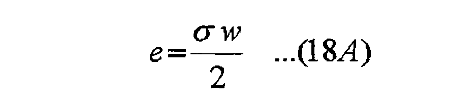
- [Formula 19]

- [Formula 20]

- In addition, regarding the definition of the effective width e, as in the following Expression (18B), there are various definitions besides the above Expression (18A). In the heat treatment method of a structural material according to this embodiment, any definition from among the various definitions may be used. In addition, a stress distribution in the width direction of the thin sheet when the thin sheet buckles under the compressive load (that is, the stress distribution as shown in
FIG. 6B ) is calculated by a numerical analysis (for example, a numerical integral such as the finite element method), and from the stress distribution calculated as described above, the effective width e that satisfies the above Expression (14) may be calculated. - [Formula 21]

- In consideration of the effective width e as described above, even in the
structural material 10 illustrated inFIG. 2 and the like, the area in each of theflat portions 11 that mainly receives the compressive load is an area of which the distance in the width direction from the bent portion 12 (that is, a direction perpendicular to the longitudinal direction of the structural material 10) is within the effective width e. Hereinafter, such an area, that is, the area having a bent portion of which the distance in the width direction from a certain bent portion is within the effective width e is referred to as an effective width area. The effective width areas (effective width areas 15 inFIGS. 2 and3 ) are shown by oblique lines inFIG. 2 and the entirety thereof is shaded inFIG. 3 . - As such, in the heat treatment method of a structural material according to this embodiment, the effective width of an untreated structural material having at least one bent portion as illustrated as the bent portions 12 (12a to 12d) of
FIG. 3 (bent portions of a structural material) is determined. - In the heat treatment method of a structural material according to this embodiment, a heat treatment (here, a laser heat treatment as an example) is performed on a part of the effective width area determined as described above. Hereinafter, the ratio of the area on which the laser heat treatment to the effective width area is performed will be described.
-
FIG. 7 shows a true stress-true plastic strain curve of a steel sheet in a grade of a tensile strength of 440 MPa. By using the linear hardening law, as shown inFIG. 7 , as work-hardening characteristics immediately after the yield of the steel sheet having such stress-strain characteristics, the work-hardening coefficient Eh is expressed by the following Expression (21). In Expression (21), εp represents strain after the steel sheet yields (plastic strain), and σh represents stress when the plastic strain is εp. In addition, inFIG. 7 andFIGS. 9A and 9B described later, σh is described as a stress when the plastic strain εp is 1%. As shown in the figures, σh may be determined from the stress when the plastic strain εp is 1%. - [Formula 22]

- Regarding the elastic-plastic buckling phenomenon of such a steel sheet, a theoretical expression that expresses the elastic-plastic buckling stress σp,Cr as a function of the work-hardening coefficient Eh is proposed, and the elastic-plastic buckling stress σp,Cr is expressed by, for example, the following Expression (22). In the following Expression (22), w is the width of the steel sheet, t is the thickness of the steel sheet, and k is the coefficient corresponding to the sheet shape or the like. As can be seen from Expression (22), the elastic-plastic buckling stress σp,Cr increases in proportion to the work-hardening coefficient Eh.
- [Formula 23]

- Here, from the idea that the initial peak stress σ1 shown in
FIG. 1 has the same tendency as the elastic-plastic buckling stress σp,Cr, it is thought that the initial peak stress σ1 also increases in proportion to the work-hardening coefficient Eh. In addition, Expression (22) represents the elastic-plastic buckling stress σp,Cr in a steel sheet as illustrated inFIG. 6A and does not represent the elastic-plastic buckling stress σp,Cr regarding a structural material having a polygonal cross-section as illustrated inFIG. 3 . However, when the cross-sectional shape of a structural material is made polygonal, the cross-sectional shape of the structural material becomes close to a cylindrical shape, and the elastic-plastic buckling stress σp,Cr of a cylindrical shell can be expressed by the following Expression (23). In Expression (23), R is the diameter of a cylinder. - [Formula 24]

- As can be seen from Expression (23), even in the cylindrical shell, the elastic-plastic buckling stress σp,Cr increases in proportion to the work-hardening coefficient Eh. Therefore, even in the cylindrical shell, it is thought that the initial peak stress σ1 increases in proportion to the work-hardening coefficient Eh.
-
FIG. 8 shows true stress-true strain curves of an untreated steel sheet in a grade of a tensile strength of 440 MPa and the material of a steel sheet in a grade of a tensile strength of 440 MPa of which the entirety is subjected to a heat treatment (is quenched). The solid line ofFIG. 8 represents the true stress-true strain curve of the untreated steel sheet, and the broken line represents the true stress-true strain curve of the steel sheet after the heat treatment. - Regarding the steel sheet after the heat treatment shown in
FIG. 8 , when the work-hardening coefficient Eh immediately after the yield is calculated by applying the linear hardening law as shown inFig. 7 , the work-hardening coefficient of the untreated steel sheet Eh0 can be expressed by the following Expression (24) (seeFIG. 9A ). In Expression (24), σY0 represents the yield stress of the untreated steel sheet, εY0 represents the true strain of the untreated steel sheet at the yield stress, εh0 represents a predetermined true strain greater than εY0, and σh0 represents the stress (corresponding to a flow stress described later) of the untreated steel sheet when the true strain is εh0. On the other hand, the work-hardening coefficient of the steel sheet after the heat treatment EhM can be expressed by the following Expression (25) (seeFIG. 9B ). In Expression (25), σYM represents the yield stress of the steel sheet after the heat treatment, εYM represents the true strain of the steel sheet after the heat treatment at the yield stress, εhM represents a predetermined true strain greater than εYM, σhM represents the stress (corresponding to a flow stress described later) of the steel sheet after the heat treatment when the true strain is εhM. - [Formula 25]

- [Formula 26]

- As can be seen from
FIGS. 8 ,9A, and 9B , when the heat treatment is performed on the entire steel sheet, the work-hardening coefficient of the steel sheet after the heat treatment EhM is greater than the work-hardening coefficient of the steel sheet before the heat treatment Eh0. Therefore, in the case where the heat treatment is performed on the entire steel sheet, the steel sheet after the heat treatment has a greater initial peak stress σ1 than that of the steel sheet before the heat treatment. - As such, it is found that between the untreated steel sheet and the steel sheet of which the entirety is subjected to the heat treatment, the steel sheet of which the entirety is subjected to the heat treatment has a greater initial peak stress σ1. However, in a case where the heat treatment is partially performed on the steel sheet, the relationship between the ratio at which the heat treatment is performed on the steel sheet, that is, the ratio of an area which is hardened to a predetermined or higher hardness by the heat treatment (hereinafter, referred to as a hardened area) to the entire steel sheet and the initial peak stress is found to be unclear.
- Here, the inventors obtained the following knowledge as a result of examining the relationship between the volume fraction fM the work-hardening coefficient Eh of the steel sheet after the partial hardening, and the initial peak stress σ1 when the volume fraction of the hardened area (hardening ratio) fM with respect to the entire steel sheet is changed from 0 to 100%. Hereinafter, the obtained knowledge will be described in detail.
- First, in the case where the volume fraction of the hardened area with respect to the entire steel sheet fM is changed from 0 to 100%, it is thought that the proof stress σh of the steel sheet and the yield stress σY thereof when 5% of plastic strain occurs change as shown in
FIG. 10 . - That is, as shown in
FIG. 10 , the proof stress σh of the steel sheet when 5% of plastic strain occurs may be approximated by a substantially straight line with respect to the volume fraction fM. This is because when a certain degree of limited plastic strain is given to the entire steel sheet, substantially the same plastic strain is exerted on both the hardened area and the non-hardened area (an area of the steel sheet other than the hardened area, that is, an untreated area). - Therefore, the proof stress σh after giving 5% of plastic strain with respect to the volume fraction of the hardened area fM is expressed by the following Expression (26) as a function of the volume fraction fM.
- [Formula 27]

- As such, even though an approximation that the proof stress σh of the steel sheet is proportionate to the volume fraction of the hardened area fM (the amount of change of the rate of change in the flow stress with respect to the hardening ratio is substantially 0) is performed, the relationship between the proof stress σh of the steel sheet and the volume fraction of the hardened area fM can be sufficiently and accurately expressed.
- On the other hand, as in
FIG. 10 , when the yield stress σY is approximated by a convex downward curve (for example, a quadratic function) other than a straight line, the yield stress σY is more accurately expressed using the volume fraction of the hardened area fM. When the volume fraction of the hardened area fM is small, the characteristics of the non-hardened area having a relatively small yield stress becomes dominant in the yield phenomenon, and the entire yield stress becomes close to the yield stress of the non-hardened area (see Expression (27)). On the other hand, when the volume fraction of the hardened area fM increases by a certain degree, the influence of the characteristics of the hardened area increases when the yield phenomenon occurs. In particular, when the volume fraction of the hardened area fM becomes 1, the entire yield stress becomes equal to the yield stress of the hardened area (see Expression (28)). - [Formula 28]

- [Formula 29]

- Therefore, in the case where the yield stress σY is approximated by the quadratic function of the volume fraction of the hardened area fM, the yield stress σY(σY(fM)) can be expressed by the following Expression (29) as a function of the volume fraction fM. In addition, in Expression (29), a, b, and c are constants.
- [Formula 30]

- Here, when Expression (29) is differentiated once with respect to the volume fraction fM and the volume fraction fM is substituted by 0, the constant b of the above Expression (29) can be represented by the following Expression (30). That is, the constant b can be approximated by the gradient of the change in the yield stress σY(fM) with respect to the volume fraction fM when the volume fraction of the hardened area fM is 0.
- [Formula 31]

- When Expressions (26) to (30) obtained as described above are substituted in Expression (21), the work-hardening coefficient Eh is expressed by a function of the volume fraction of the hardened area fM, that is, the following Expression (31).
- [Formula 32]

- Here, for example, assuming that the plastic strain εp is 0.05, the yield stress of the hardened area σYM is 794 MPa, the yield stress of the non-hardened area σY0 is 301 MPa, the proof stress σhM of the hardened area when the plastic strain εp is given is 1017 MPa, the proof stress σh0 of the non-hardened area when the plastic strain εp is given is 447 MPa, and b is 350 MPa, σh(fM) calculated by Expression (26) and σY(fM) calculated by Expression (29) can be expressed by
FIG. 11 . In addition, here, the work-hardening coefficient Eh(fM) calculated by Expression (31) can be expressed byFIG. 12 . - For example, as can be seen from Expression (31), in a case where the yield stress σY is approximated by a quadratic function (a convex downward function the volume fraction fM in a range of 0 to 1) of the volume fraction of the hardened area fM, the work-hardening coefficient Eh(fM) can also be expressed as a quadratic function (a convex upward function of the volume fraction fM in a range of 0 to 1) of the volume fraction of the hardened area fM. Accordingly, as can be seen from
FIG. 12 , the work-hardening coefficient Eh(fM) is maximized at a specific volume fraction fM-max. Therefore, there may be cases where the work-hardening coefficient Eh(fM) is higher than the work-hardening coefficient which is when the volume fraction of the hardened area fM is 1 (100%) depending on the volume fraction of the hardened area fM. In the example shown inFIG. 12 , when the volume fraction of the hardened area fM is fM-min to 1, the work-hardening coefficient Eh is higher than or equal to the work-hardening coefficient Eh (fM=1) which is when the volume fraction of the hardened area fM is 1 (100%). In other words, in the example shown inFIG. 12 , the initial peak stress when the volume fraction of the hardened area fM is fM-min to 1 becomes higher than or equal to the initial peak stress which is when the volume fraction of the hardened area fM is 1 (100%) (that is, when the heat treatment is performed on the entire effective width). - However, as described above, as the heat treatment for locally hardening a part of the steel sheet, for example, the laser heat treatment is used. In such a laser heat treatment, the amount of energy consumed increases as the treatment area increases, resulting in an increase in manufacturing cost. Accordingly, in terms of a reduction in manufacturing cost, it is preferable that an area on which the laser heat treatment be as narrow as possible.
- Here, as described above, when the volume fraction of the hardened area fM is higher than or equal to fM-min, the work-hardening coefficient Eh can be increased to be higher than or equal to the work-hardening coefficient Eh(fM=1) which is when the volume fraction of the hardened area fM is 1 (100%). As a result, the initial peak stress can be increased to be higher than or equal to the initial peak stress which is when the volume fraction of the hardened area fM is 1 (100%). Here, it is preferable that the volume fraction of the hardened area fM be controlled to be higher than the volume fraction fM-min (hereinafter, referred to as "minimum volume fraction") which is when the work-hardening coefficient Eh(fM=1) which is when the volume fraction of the hardened area fM is 1 (100%) becomes equal to the work-hardening coefficient Eh(fM=fM-min) thereof.
- In addition, for example, in the case where the yield stress σY is approximated by a quadratic function of the volume fraction of the hardened area fM, the minimum volume fraction fM-min is expressed by the following Expression (32). In Expression (32), Δσh is the difference between σhM and σh0 (Δσh=σhM-σh0), ΔσY is the difference between σYM and σY0 (ΔσY=σYM-σY0). In particular, in the case of the conditions as described above (that is, the case of the conditions shown in
FIGS. 11 and12 ), the minimum volume fraction fM-min is 53.3%. In addition, since the minimum volume fraction fM-min needs to satisfy 0<fM-min<1, the constants b and Δσh also need to satisfy 0<b<2ΔσY-Δσh and ΔσY<Δσh<2ΔσY. - [Formula 33]

- In addition, as described above, the work-hardening coefficient Eh(fM), that is, the initial peak stress is maximized at a specific volume fraction fM-max. Accordingly, in terms of increasing the initial peak stress while narrowing the area on which the laser heat treatment is performed, it is preferable that the volume fraction of the hardened area fM be controlled to be less than or equal to the volume fraction fM-max which is when the work-hardening coefficient Eh(fM) is maximized.
- Otherwise, in terms of maximizing the peak stress of a steel sheet (structural material), it is preferable that the volume fraction of the hardened area fM be controlled to be the volume fraction fM-max which is when the work-hardening coefficient Eh(fM) is maximized. Therefore, the volume fraction of the hardened area fM may be controlled to be the volume fraction fM-max (hereinafter, referred to as "maximum volume fraction") which is when the work-hardening coefficient Eh(fM) is maximized.
- In addition, for example, in the case where the yield stress σY is approximated by a quadratic function of the volume fraction of the hardened area fM, the maximum volume fraction fM-max is expressed by the following Expression (33). In particular, in the case of the conditions as described above (that is, the case of the conditions shown in
FIGS. 11 and12 ), the maximum volume fraction fM-max is 76.6%. In addition, even in this case, since the maximum volume fraction fM-max needs to satisfy 0<fM-max<1, the constants b and Δσh also need to satisfy 0<b<Δσh and 0<b<ΔσY. - [Formula 34]

- However, the relationship between the volume fraction of the hardened area fM described above and the initial peak stress or the work-hardening coefficient Eh is a relationship obtained for a steel sheet, and is not a relation obtained for, for example, the
structural material 10 having the shape as illustrated inFIG. 2 . Here, in thestructural material 10 illustrated inFIG. 2 , as described above, areas that mainly receive the compressive load is theeffective width areas 15, and theeffective width areas 15 can be assumed to be a steel sheet having a width of 2xe. Therefore, the volume fraction of the hardened area fM in such an effective width area, that is, the ratio of an area in the effective width area on which a hardening treatment (for example, a laser heat treatment) is performed can be set by the method as described above. - For example, the laser heat treatment is performed so that the volume fraction of the hardened area fM in each of the
effective width areas 15 becomes higher than or equal to fM-min expressed by Expression (32) and less than or equal to fM-max expressed by Expression (33). In addition, in this case, σhM, σh0, σYM, and σY0 regarding Δσh(=σhM-σh0) and ΔσY(=σYM-σY0) in Expressions (32) and (33) respectively represent the proof stress of the heat-treated area (hardened area) when a predetermined strain is given, the proof stress of the untreated area (non-hardened area) when a predetermined strain is given, the yield stress of the heat-treated (hardened area), and the yield stress of the untreated area (non-hardened area). In addition, σhM, σh0, σYM, and σY0 are parameters regarding the material (steel sheet) used in the structural material. - By setting the volume fraction of the hardened area fM in each of the
effective width areas 15 as described above, the initial peak stress of thestructural material 10 can be increased while causing the area on which the laser heat treatment is performed to be small. - In the above description, the volume fraction of the hardened area fM in each of the
effective width areas 15 is controlled to be higher than or equal to fM-min and less than or equal to fM-max. However, as described above, the volume fraction of the hardened area fM may also be controlled to be higher than or equal to fM-min and less than or equal to 1 (100%) or less than 1. In this case, it may be determined that the volume fraction of the hardened area fM in each of theeffective width areas 15 is set so that the work-hardening coefficient Eh of each of theeffective width areas 15 becomes equal to or higher than the work-hardening coefficient which is when the entire area of theeffective width areas 15 is hardened by the laser heat treatment. Otherwise, as described above, the volume fraction of the hardened area fM in each of theeffective width areas 15 may also be controlled to be fM-max.
In summary, as shown inFIG. 17 , the minimum value of the volume fraction fM is determined on the basis of the rate of change of the yield stress σY with respect to the volume fraction fM in the case where the volume fraction of the hardened area fM is 0, the rate of change (constant) is called b (S311), and the maximum value of the range of the volume fraction fM is determined to be less than or equal to 1 or less than 1 (S312), thereby the range of the volume fraction of the hardened area fM may be determined. In addition, after determining the minimum value of the range of the volume fraction fM (S311), the maximum value of the range of the volume fraction fM may also be determined on the basis of the rate of change of the yield stress σY with respect to the volume fraction fM in the case where the volume fraction of the hardened area fM is 0, the rate of change (constant) is called b (S313). - Here, an example of a method of determining the constant b for determining the range of the volume fraction of the hardened area fM described above will be described. As a first method, a tensile test is performed on three specimens of which the volume factions fM of the hardened areas of steel sheets are 0, 1, and an arbitrary value that is higher than 0 and less than 1 (for example, 0.5), the yield stresses σY of the specimens are obtained, and the method of least squares is performed thereon, thereby the constants a, b, and c can be determined. As a second method, a tensile test is performed on two specimens of which the volume factions fM of the hardened areas of steel sheets are 0, and an arbitrary value that is higher than 0 and close enough to 0 (for example, 0.1), the yield stresses σY of the specimens are obtained, and the constant b can be determined as the rate of increase in the yield stress σY with respect to the volume faction of the hardened area fM. Here, the method of determining the constant b using the minimum number of pieces of data needed (the number of pieces of data of the yield stresses σY) as a simple method has been described. However, the upper limit of the number of pieces of data is not particularly limited. As the number of pieces of data increases, the range of the volume fraction fM can be determined with higher precision.
- Moreover, the yield stress σY and the proof stress σh can be measured by performing a tensile test according to JIS Z2241 on JIS No. 5 specimens (specimens) sampled from a steel sheet (no heat treatment and bending process) used as structural material. In particular, for measurement of the yield stress σYM and the proof stress σhM in the case where the volume fraction of the hardened area fM is 1, specimens obtained by performing a predetermined heat treatment on the above specimens may be used. As the predetermined heat treatment, for example, the specimens may be heated to the Ae3 point (Ae3 temperature) or higher, and thereafter may be cooled to the Ms point (Ms temperature) or less at a cooling rate of higher than or equal to 10 °C/s, and preferably higher than or equal to 30 °C/s by cooling means such as water cooling and/or air cooling.
- In addition, for measurement of the yield stress σYM and the proof stress σhM in the case where the volume fraction of the hardened area fM is higher than 0 and less than or equal to 1, the tensile test described above may be performed on the above specimens which is performed a laser heat treatment in the longitudinal direction under the conditions corresponding to the abovementioned predetermined heat treatment. In this case, by measuring the volume fraction of the hardened area fM after the tensile test, the correspondence relationship between the volume fraction fM, the yield stress σYM, and the proof stress σhM may be determined. For controlling the volume fraction of the hardened area fM by the laser heat treatment, the laser heat treatment (1 pass) may be repeatedly performed on one surface or both surfaces of the specimens in the longitudinal direction of the specimens while displacing the positions of the specimens in the width direction (a direction perpendicular to the longitudinal direction).
In addition, as the steel sheet used for the specimens, specimens on which a strain history corresponding to the bend-processed portion (bent portion) of the structural material before the heat treatment is applied may also be used. - In addition, the volume fraction of the hardened area fM can be determined by a method as follows. For example, the area of the hardened area in a cross-section perpendicular to the longitudinal direction of the specimen is measured, and the volume of the hardened area is obtained by multiplying the area by a length (total length) on which the laser heat treatment is performed, and the volume of the hardened area is divided by the total volume of the specimen, thereby the volume fraction of the hardened area fM can be obtained. In addition, the area of the hardened area may be determined from a quenched structure observed with an optical microscope from the cross-section perpendicular to the longitudinal direction of the specimen, and may also be determined by obtaining the Vickers hardness using a Vickers hardness tester as described later.
- In addition, in the method of determining the range of the volume fraction of the hardened area fM described above, the relationship between the proof stress σh of the steel sheet and the volume fraction of the hardened area fM is expressed by a linear function, and the relationship between the yield stress σY of the steel sheet and the volume fraction of the hardened area fM is expressed by a quadratic function. However, such functions may not be necessarily used.
In order to determine the range of the volume fraction of the hardened area fM, the fact that the rate of change in the yield stress with respect to the volume fraction of the hardened area fM varies depending on the volume fraction of the hardened area fM and the amount of change (a degree of change) is greater than the amount of change (a degree of change) of the rate of change in flow stress with respect to the volume fraction of the hardened area fM may be used.
Therefore, for example, the relationship between the yield stress σY of the steel sheet and the volume fraction of the hardened area fM may be expressed by an arbitrary function σY(fM), and the range of the volume fraction of the hardened area fM may be determined using the rate of change in the yield stress (in a case of a quadratic function, corresponding to the constant b) with respect to at least one hardening ratio. In a case where the quadratic function is extended to a general function, the minimum volume fraction fM-min (other than 1) and the maximum volume fraction fM-max may be determined to satisfy the following Expressions (34) and (35). Here, σY(fM) can be expressed as a function including the constant b described above. - [Formula 35]

- [Formula 36]
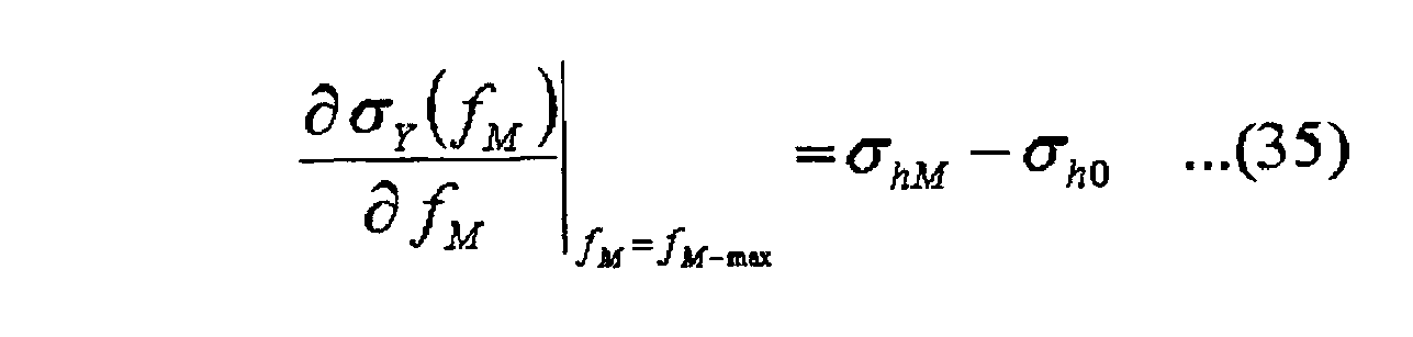
- In addition, the relationship between the proof stress σh of the steel sheet and the volume fraction of the hardened area fM may be expressed by an arbitrary function σh(fM). Here, in a case where the linear function and the quadratic function described above are extended to general functions, the maximum volume fraction fM-max can be determined to satisfy the following Expression (36).
- [Formula 37]

- Moreover, other than in the above-described range (for example, of higher than or equal to fM-min and less than or equal to 1 (less than 1) or in the range of the following Expression (41)), for example, using the maximum volume fraction (boundary hardening ratio) fM-max, the range of the volume fraction of the hardened area fM may be determined within the range of any of the following Expressions (37) to (40).
- [Formula 38]

- [Formula 39]

- [Formula 40]

- [Formula 41]

- [Formula 42]

- By determining the range of the volume fraction of the hardened area fM as in the above Expressions (37) to (41), a stable heat treatment can be performed with an excellent balance between a reduction of cost of the heat treatment and the enhancement of the ability of the structural material to suppress deformation. In addition, correction terms including cost, heat treatment conditions, and the like may be appropriately included as the upper limit and lower limit in the range of the volume fraction of the hardened area fM.
- Moreover, besides the above-described range, as shown in
FIG. 16 , the work-hardening coefficient Eh (the relationship between the volume fraction fM and the work-hardening coefficient Eh) is estimated or calculated on the basis of the range of change in the yield stress σY with respect to the volume fraction of the hardened area fM (S301), and the range of the volume fraction fM may be determined so that the estimated or calculated work-hardening coefficient Eh becomes higher than or equal to a predetermined value (S302). For example, the difference between the work-hardening coefficient Eh in the case where the volume fraction fM is 1 and the work-hardening coefficient Eh in the case where the volume fraction fM is fM-max is defined as ΔEh, an arbitrary value that is higher than or equal to 0 and less than or equal to 1 is defined as an improvement coefficient n, and a value obtained by adding n×Δh to the work-hardening coefficient Eh in the case where the volume fraction fM is 1 may be determined as a predetermined value. Therefore, the predetermined value may be the work-hardening coefficient Eh in the case where the volume fraction of the hardened area fM is 1. In addition, instead of the work-hardening coefficient Eh expressed by the above Expression (21), a different index of work-hardening including the yield stress σY as at least a variable may also be used. - In addition, when the relationship between the proof stress σh of the steel sheet and the volume fraction of the hardened area fM is expressed by a linear function and the relationship between the yield stress σY of the steel sheet and the volume fraction of the hardened area fM is expressed by a quadratic function, the range of the volume fraction of the hardened area fM can be determined most simply. In this case, the range of the volume fraction of the hardened area fM can be determined using the constant a instead of the constant b. However, as expressed by the following Expression (42), the constant a can be expressed using the constant b (the constant a is a dependent variable of the constant b), and thus it is assumed that the use of the constant a is the same as the use of the constant b. Similarly, even in the case where a variable (for example, the rate of change in the yield stress σY with respect to the volume fraction fM in the case where the volume fraction fM is 1) which is subordinate to the range of change in the yield stress σY with respect to the volume fraction fM is used, it is assumed that the rate of change in the yield stress σY with respect to the volume fraction fM is used. That is, as expressed by the following Expression (43) obtained by substituting the first order differential equation of the above Expression (29) with the following Expression (42), b which is the range of change in the yield stress σY in the case where the volume fraction fM is 0 can also be obtained using the rate of change in the yield stress σY at an arbitrary volume fraction fM. For example, as expressed by the following Expression (44), even in the case where the rate of change in the yield stress σY in the case where the volume fraction fM is 1 is defined as d, b can be obtained using d from the following Expression (45).
- [Formula 43]

- [Formula 44]

- [Formula 45]

- Moreover, the range of the volume fraction fM can be determined on the basis of the volume fraction fM which is when the rate of change in the yield stress σY with respect to the volume fraction of the hardened area fM satisfies a predetermined condition. For example, upon considering that the work-hardening coefficient Eh draws a convex downward curve with respect to the volume fraction of the hardened area fM, the volume fraction fM which is when the first order differential of the work-hardening coefficient Eh expressed by the above Expression (21) with respect to volume fraction fM becomes 0, that is, the volume fraction (boundary hardening ratio) fM that satisfies the above Expression (36) may be determined as the maximum volume fraction fM-max. In this case, the range of the volume fraction of the hardened area fM can be determined as, for example, a range that satisfies the above Expressions (37) to (41). Here, regarding Expressions (37) to (41), the minimum volume fraction fM-min (other than 1) can be determined using the above Expression (34). In addition, ΔEh described above is determined from the minimum volume fraction fM-min and the maximum volume fraction fM-max determined by Expressions (34) and (36), and the range of the volume fraction fM may be determined using the improvement coefficient n described above so that the work-hardening coefficient Eh is higher than or equal to a value obtained by adding n×ΔEh to the work-hardening coefficient Eh in the case where the volume fraction fM is 1.
That is, as shown inFIG. 18 , the maximum volume fraction fM-max of the volume fraction fM is determined on the basis of the rate of change in the yield stress σY with respect to the volume fraction of the hardened area fM (S321), the minimum value of the range of the volume fraction fM is determined as a value smaller than the maximum volume fraction fM-max by a predetermined value (S322), and the maximum value of the range of the volume fraction fM may be determined to be less than or equal to 1 or less than 1 (S323). In addition, after determining the minimum value of the range of the volume fraction of the hardened area fM (S322), the maximum value of the range of the volume fraction fM may be determined to be a value greater than the maximum volume fraction fM-max by a predetermined value (S324). - In addition, regarding the relationship between the yield stress σY of the steel sheet and the volume fraction of the hardened area fM, the same function (for example, a linear function such as a quadratic function) may be used in a range in which the volume fraction fM is 0 to 1, however, this range may be divided into a plurality of ranges and the different functions may also be used for each ranges. However, since the change in the rate of change in the yield stress σY with respect to the volume fraction fM is used, in the case where the same function is used in the range in which the volume fraction is 0 to 1, the function in this range needs to be able to differentiated twice with respect to the volume fraction fM. In addition, as a method of dividing the range of 0 to 1 into a plurality of ranges and using different functions for each ranges, for example, an interpolation function (including a case where the interpolation function is linear (a graph of broken line)) according to various interpolation methods (for example, spline interpolation) may be used. In this case, actual measurement data (for example, 5 or more points) can be directly used as data of a database.
Similarly, even regarding the relationship between the flow stress σh of the steel sheet and the volume fraction of the hardened area fM, the same function (for example, a linear function such as a linear function) may also be used in a range in which the volume fraction fM is 0 to 1, however, this range may be divided into a plurality of ranges and different functions may also be used for each ranges. - Here, as described above, in order to determine the range of the volume fraction of the hardened area fM using as low a number of measurements (the number of instances of manufacturing of the specimens and the number of tests of tensile strength) as possible, it is preferable that the relationship between the proof stress σh of the steel sheet and the volume fraction of the hardened area fM be expressed by a linear function and the relationship between the yield stress σY of the steel sheet and the volume fraction of the hardened area fM be expressed by a quadratic function.
- In addition, in the above embodiments, σh(fM) is defined as the proof stress which is when 5% of plastic strain occurs. However, the plastic strain corresponding to the proof stress may not be necessarily limited to 5% and may not be 5% as long as it is greater than 0%. For example, as shown in
FIGS. 7 ,9A, and 9B , σh(fM) can also be defined as a proof stress which is when 1% of plastic strain occurs. Therefore, when a proof stress which is when a predetermined plastic strain occurs (or a stress needed to cause plastic deformation from a state where a predetermined plastic strain occurs) is defined as a flow stress, σh(fM) represents the flow stress, σhM represents the flow stress of the hardened area, σh0 represents the flow stress of the non-hardened area (untreated structural material).
Here, the flow stress may be a stress at a stain amount determined in a range which is greater than a strain amount (that is, the plastic strain is greater than 0) corresponding to the yield stress and smaller than a uniform elongation strain amount (for example, the maximum amount of nominal strain). As general evaluation, it is preferable that the flow stress be 5%. - In addition, in the above description, the
structural material 10 is locally heated and hardened by the laser heat treatment. However, local hardening of thestructural material 10 may not necessarily be performed by the laser heat treatment and may also be performed by another heat treatment. In any case, it is preferable that the hardness of the area hardened by the heat treatment be higher than or equal to the reference hardness (Vickers hardness) Hv calculated by the following Expressions (45) and (46) when the carbon content of thestructural material 10 which is a steel material is defined as C, the silicon content is defined as Si, the manganese content is defined as Mn, the nickel content is defined as Ni, the chromium content is defined as Cr, the molybdenum content is defined as Mo, the niobium content is defined as Nb, the vanadium content is defined as V. - [Formula 46]

- [Formula 47]

- Moreover, in the embodiment shown in
FIGS. 2 and3 , the laser heat treatment is performed on theeffective width areas 15 in the peripheries of the twobent portions effective width areas 15 in the peripheries of the two differentbent portions effective width area 15 in the periphery of one bent portion of the twobent portions - In addition, a heat-treated structural material according to an embodiment of the present invention will be described.
The heat-treated structural material according to this embodiment includes, as in the above embodiment, at least one bent portion which extends in one direction of the structural material and has a bend in a direction perpendicular to the one direction. Therefore, the heat-treated structural material according to this embodiment includes, for example, structural materials having shapes as illustrated inFIGS. 2 to 5 . Moreover, the volume fraction fM of the above-described hardened area with respect to the above-described effective width areas is less than 1 and is included in the range of the volume fraction fM determined on the basis of the rate of change in the yield stress σY with respect to the volume fraction fM.
Thereafter, the heat-treated structural material according to this embodiment may exhibit a higher ability to suppress deformation than that according to the conventional technique while maintaining costs as low as possible.
Moreover, the range of the volume fraction of the hardened area fM can be determined on the basis of the rate of change in the yield stress σY with respect to the volume fraction fM in the case where the value of the volume fraction fM is 0 as described above. The range of the volume fraction fM is a range determined so that the work-hardening coefficient Eh calculated on the basis of the rate of change in the yield stress σY with respect to the volume fraction fM is higher than or equal to a predetermined value. In particular, the predetermined value is preferably the value of the work-hardening coefficient Eh in the case where the volume fraction fM is 1, and more preferably a value greater than the work-hardening coefficient Eh in the case where the volume fraction fM is 1. In addition, it is preferable that the range (lower limit) of the volume fraction of the hardened area fM be higher than or equal to the minimum volume fraction fM-min expressed by the above Expression (32). Similarly, it is preferable that the range (upper limit) of the volume fraction of the hardened area fM be lower than or equal to the maximum volume fraction fM-max expressed by the above Expression (33). In addition, three JIS No. 5 specimens are sampled from the flat portion of the structural material, the heat treatment is performed on the two specimens so that the volume fractions fM of the hardened areas of the specimens are 0, 1, and 0.5, a tensile test is thereafter performed on the three specimens to obtain needed mechanical strengths, and the method of least squares is performed on the relationship between the yield stress σY and the volume fraction fM, thereby determining the constant b of Expression (30). - In addition, the flow stress may be defined as a proof stress which is when 5% of plastic strain occurs. Moreover, in order to determine the effective width area, the effective width e may be defined by the above Expressions (15), (17), and (18B) or the following Expression (47). In addition, in the case where the effective width e is defined by Expression (15), the finite element method may be used. In addition, Expression (47) is derived from the above Expressions (18A) to (20) assuming that the flat sheet buckling coefficient is 4.
- [Formula 48]

- In addition, the hardened area (the area hardened by the heat treatment) may be obtained by the same method as that of the embodiment. That is, the hardened area can be determined to be an area that has a hardness of higher than or equal to the Vickers hardness calculated by above Expressions (45) and (46). In addition, it is preferable that the heat treatment be performed using a laser. The history of the heat treatment using the laser may be checked by observing the structure of the cross-section of the structural material.
- From a single 440 MPa-grade steel sheet BP having a thickness of 1.0 mm, a yield stress of 301 MPa, a tensile strength of 457 MPa, an elongation of 39%, a carbon content of 0.09%, a silicon content of 0.02%, a manganese content of 1.24%, 11 JIS No. 5 specimens were sampled. A laser heat treatment was performed in a plurality of passes on the 10 specimens among the specimens in the longitudinal direction (tension direction) of the specimens to achieve predetermined volume fractions, thereby manufacturing specimens in which the volume fractions of the hardened areas with respect to effective width areas were 0.1 to 1 (increment of 0.1). As the laser heat treatment, a carbon dioxide laser was used, a laser output was controlled to 5 kW, and a heat treatment speed was controlled to 12 m/min. Moreover, a tensile test was performed on the 11 specimens to evaluate yield stresses and tensile stresses.
- As a result, from the untreated specimen, the yield stress of the non-hardened area σY0 was determined as 301 MPa, and the proof stress σh0 of the non-hardened area when a plastic strain εp of 0.05 (0.0537) was given was determined as 447 MPa. Similarly, from the specimen having a volume fraction of 1 (100%), the yield stress of the hardened area σYM was determined as 794 MPa, and the proof stress σhM of the hardened area when a plastic strain εp of 0.05 (0.0537) was given was determined as 1017 MPa. Moreover, the yield stresses obtained from the 11 specimens were plotted with respect to the volume fractions, and the method of least squares using the above Expression (29) as a regression equation was applied to the plot, thereby determining the constant b as 350 MPa. Here, it was confirmed that even when the method of least squares was performed on the three plots of the yield stress of the untreated specimen, the specimen having a volume fraction of 0.5 (50%), and the specimen having a volume fraction of 1 (100%), the same constant b was obtained.
As a result of substituting the value of b (b=350 MPa), the values of Δσh and ΔσY (Δσh=569.2 MPa, ΔσY=493.0 MPa) obtained by the tensile test in Expression (32), fM-min=53.3% was obtained.
In addition, as a result of substituting the value of b and the values of Δσh and ΔσY in Expression (33), fM-max (fM-max=76.6%) was obtained. - In addition, as a result of calculating the effective width e using the above Expressions (18A) to (20) (or the above Expression (47)), 19.2 mm was obtained as the effective width e. Here, the flat sheet buckling coefficient k which is a coefficient in response to the sheet shape or the like was 4, the sheet width w was 60 mm, the sheet thickness t was 1.0 mm, the yield stress σY0 was 301 MPa, and the elastic modulus E was 180 GPa. In addition, regarding the sheet width w, the average value (60 mm) of the height (50 mm) illustrated in
FIG. 14 and the width (70 mm) of the top portion was used as a representative value. - In addition, the steel sheet BP (
FIG. 13A ) was subjected to a bending process, thereby manufacturing an untreatedstructural material 10 having a shape as illustrated inFIG. 13B . The untreatedstructural material 10 includes five flat portions which are arranged so that the cross-section thereof has a hat shape as illustrated inFIG. 14 . The lengths of sides in the vertical cross-section of the sides including the threeflat portions 11 at the center were 50 mm, 70 mm, and 50 mm, respectively. - The untreated
structural material 10 manufactured as such was spot-welded to a differentstructural material 20 having a flat sheet shape, thereby manufacturing a structural material assembly as illustrated inFIG. 13 . Spot welding S was performed on the center in the width direction of the flat portions constituting flange portions at an interval of 30 mm in the longitudinal direction. In addition, the distance from the end portion in the longitudinal direction (the end portion on a side on which an impact is inserted, hereinafter, referred to as "impact exertion side end portion") to the initial spot weld was 15 mm. - On the structural material assembly manufactured as such, the laser heat treatment was performed in a plurality of passes in the longitudinal direction (tensile direction) of the specimens using the carbon dioxide laser. The laser output was controlled to 5 kW, and the heat treatment speed was controlled to 12 m/min. The laser output and the heat treatment speed in the laser heat treatment were controlled in the same manner in the following examples. In a test No. 1, the laser heat treatment was performed over the entirety of an area of 19.2 mm from the bent portion shaded in black in
FIG. 14 , that is, over the entirety of the effective width area. Therefore, in this case, the volume fraction of the hardened area with respect to the effective width area was 100%. Here, the work-hardening coefficient Eh calculated by the above Expression (31) using the above-described data was 4155.8 MPa (here,εp=0.05). - Measurement of Vickers hardness was performed on the spots on which the laser heat treatment was performed. While the Vickers hardness of the untreated structural material was 140, the Vickers hardness after the laser heat treatment was 306. It was confirmed that the hardened area was sufficiently quench-hardened.
- The structural material assembly was installed so that the longitudinal direction of the structural material assembly on which the laser heat treatment was performed as such was aligned with the vertical direction and the impact exertion side end portion thereof has an upward trend, and an impact test was performed by falling a falling weight of 300 kg positioned immediately thereon from a height of 2 m.
- When the impact test was performed, a load meter (load cell) was installed immediately under the structural material assembly, and the load history after the falling weight came in contact with the structural material assembly was measured. At the same time, the displacement history of the falling weight after the falling weight came in contact with the structural material assembly (the time history of the falling amount of the falling weight after the falling weight came in contact with the structural material assembly) was also measured by a laser displacement meter. A load-strain curve was created on the basis of the load history and the displacement history measured as such. An initial peak reaction force was calculated from the load-strain curve, and an initial peak stress was calculated from the initial peak reaction force divided by the cross-sectional area of the structural material assembly (340 mm2). The initial peak reaction force at this time was 146.9 kN, and the initial peak stress was 432.0 MPa.
- In a test No. 2, an untreated structural material assembly was manufactured as in the test No. 1, and the laser heat treatment was performed on the structural material assembly. The laser heat treatment was performed so that the volume fraction of the hardened area with respect to the effective width area becomes 76.6%. Here, the work-hardening coefficient Eh calculated by the above Expression (31) using the above-described data was 4301.6 MPa (here, εp=0.05).
- As in the test No. 1, an impact test was performed on the structural material assembly on which the laser heat treatment was performed as such, and an initial peak reaction force and an initial peak stress were calculated on the basis of the test results. The initial peak reaction force at this time was 150.6 kN, and the initial peak stress was 443.0 MPa.
- In a test No. 3, an untreated structural material assembly was manufactured as in the test No. 1, and the laser heat treatment was performed on the structural material assembly. The laser heat treatment was performed so that the volume fraction of the hardened area with respect to the effective width area becomes 53.3%. Here, the work-hardening coefficient Eh calculated by the above Expression (31) using the above-described data was 4155.8 MPa (here, εp=0.05).
- As in the test No. 1, an impact test was performed on the structural material assembly on which the laser heat treatment was performed as such, and an initial peak reaction force and an initial peak stress were calculated on the basis of the test results. The initial peak reaction force at this time was 146.3 kN, and the initial peak stress was 430.1 MPa.
- The results are collected in the following Table 1.
-
[Table 1] Test No. fM (%) Eh (MPa) Initial peak reaction force (kN) Initial peak stress (MPa) 1 100 4155.8 146.9 432.0 2 76.6 4301.6 150.6 443.0 3 53.3 4155.8 146.3 430.1 - From Table 1, it can be seen that the initial peak stress which is when the volume fraction (fM) of the hardened area with respect to the effective width area is 53.3% (=fM-min) is substantially equal to the initial peak stress which is when the volume fraction is 100%. In addition, it can be seen that the initial peak stress which is when the volume fraction of the hardened area with respect to the effective width area is 76.6% (=fM-max) is substantially equal to the initial peak stresses which is when the volume fractions are 53.3% and 100%. As such, in the test No. 3, substantially the same ability to suppress deformation to that of the test No. 1 can be obtained at lower cost than that of the test No. 1. In addition, in the test No. 2, a higher ability to suppress deformation than that of the test No. 1 can be obtained at lower cost than that of the test No. 1.
- By performing a heat treatment on appropriate spots of an untreated structural material to locally harden the structural material, the structural material having a sufficiently high ability to suppress deformation can be provided.
-
Reference Signs List 10 structural material 11 flat portion 12 bent portion 15 effective width area 20 structural material


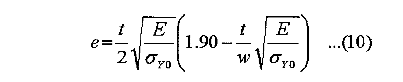


[Formula 13]

Claims (25)
- A heat treatment method of a structural material which includes a bent portion that extends in one direction of the structural material and has a bend in a direction perpendicular to the one direction, the heat treatment method comprising:determining an effective width of the bent portion e;defining an effective width area as an area which includes the bent portion and of which a distance in the direction perpendicular to the one direction from the bent portion is within the effective width;defining a hardening ratio fM as a ratio between an area which is hardened by a heat treatment in the effective width area and the effective width area;determining a range of the hardening ratio fM on the basis of a rate of change in a yield stress σY with respect to the hardening ratio fM; andperforming the heat treatment on the effective width area of the structural material to satisfy the range of the hardening ratio fM.
- The heat treatment method according to claim 1,
wherein the rate of change is a value in a case where a value of the hardening ratio fM is 0. - The heat treatment method according to claim 2,
wherein the range of the hardening ratio fM is determined so that a work-hardening coefficient Eh calculated on the basis of the rate of change is higher than or equal to a predetermined value. - The heat treatment method according to claim 3,
wherein the predetermined value is a work-hardening coefficient Eh in a case where the hardening ratio fM is 1. - The heat treatment method according to claim 2,
wherein, when a difference between a flow stress in a case where the hardening ratio fM is 1 and a flow stress in the case where the hardening ratio fM is 0 is defined as Δσh, a difference between a yield stress in the case where the hardening ratio fM is 1 and a yield stress in the case where the hardening ratio fM is 0 is defined as ΔσY, and the rate of change is defined as b, the range of the hardening ratio fM is higher than or equal to fM-min expressed by the following Expression (1) and less than 1.
[Formula 1]
- The heat treatment method according to claim 5,
wherein the range of the hardening ratio fM is less than or equal to fM-max expressed by the following Expression (2).
[Formula 2]
- The heat treatment method according to claim 1,
wherein a boundary hardening ratio fM at which the rate of change becomes equal to a rate of change in the flow stress σh with respect to the hardening ratio fM is determined as fM-max, and the range of the hardening ratio fM is determined on the basis of the fM-max. - The heat treatment method according to claim 7,
wherein the range of the hardening ratio fM is determined in a range that satisfies the following Expression (3).
[Formula 3]
- The heat treatment method according to claim 7,
wherein the range of the hardening ratio fM is determined to be higher than or equal to fM-min that satisfies the following Expression (4) and less than 1.
[Formula 4]
- The heat treatment method according to claim 1,
wherein, when a difference between a flow stress in a case where the hardening ratio fM is 1 and a flow stress in a case where the hardening ratio fM is 0 is defined as Δσh, the range of the hardening ratio fM is determined so that a difference between Δσh and the rate of change is less than or equal to a predetermined value. - The heat treatment method according to claim 1,
wherein, in a case where, regarding chemical components contained in the structural material, a mass percentage of carbon is defined as C, a mass percentage of silicon is defmed as Si, a mass percentage of manganese is defined as Mn, a mass percentage of nickel is defined as Ni, a mass percentage of chromium is defined as Cr, a mass percentage of molybdenum is defined as Mo, a mass percentage of niobium is defined as Nb, and a mass percentage of vanadium is defined as V, the area hardened by the heat treatment is an area which has a hardness higher than or equal to a Vickers hardness calculated by the following Expressions (5) and (6).
[Formula 5]
[Formula 6]
- The heat treatment method according to claim 1,
wherein the heat treatment is performed using a laser. - The heat treatment method according to claim 1,
wherein a pass of the heat treatment is continuously performed over the entire length of the one direction. - A heat-treated structural material comprising:a bent portion that extends in one direction of the structural material and has a bend in a direction perpendicular to the one direction,wherein, in a case where an area which includes the bent portion and of which a distance in a direction perpendicular to the one direction from the bent portion is within an effective width e is defined as an effective width area and a ratio of an area which is hardened by a heat treatment in the effective width area is defined as a hardening ratio fM, the hardening ratio fM is less than 1 and is contained in a range of the hardening ratio fM determined on the basis of a rate of change in a yield stress σY with respect to the hardening ratio fM.
- The heat-treated structural material according to claim 14,
wherein the rate of change is a value in a case where a value of the hardening ratio fM is 0. - The heat-treated structural material according to claim 15,
wherein the range of the hardening ratio fM is a range determined so that a work-hardening coefficient Eh calculated on the basis of the rate of change is higher than or equal to a predetermined value. - The heat-treated structural material according to claim 16,
wherein the predetermined value is a work-hardening coefficient Eh in a case where the hardening ratio fM is 1. - The heat-treated structural material according to claim 14,
wherein, when a difference between a flow stress in a case where the hardening ratio fM is 1 and a flow stress in a case where the hardening ratio fM is 0 is defined as Δσh, a difference between a yield stress in the case where the hardening ratio fM is 1 and a yield stress in the case where the hardening ratio fM is 0 is defmed as ΔσY, and the rate of change is defmed as b, the range of the hardening ratio fM is higher than or equal to fM-min expressed by the following Expression (7).
[Formula 7]
- The heat-treated structural material according to claim 18,
wherein the range of the hardening ratio fM is less than or equal to fM-max expressed by the following Expression (8).
[Formula 8]
- The heat-treated structural material according to claim 18,
wherein each of the flow stresses is defined as a proof stress which is when 5% of plastic strain occurs. - The heat-treated structural material according to claim 14,
wherein, when a width dimension perpendicular to the one direction is defined as w, a yield stress in the case where the hardening ratio fM is 1 is defined as σY0, and a stress at each position in a width direction perpendicular to the one direction when a stress at which a maximum stress in the one direction of the structural material is σY0 is given in the one direction is defined as σx, the effective width e is defined by the following Expression (9).
[Formula 9]
- The heat-treated structural material according to claim 14,
wherein, when a thickness dimension is defined as t, a Poisson's ratio is defined as v, an elastic modulus is defined as E, and a yield stress in a case where the hardening ratio fM is 0 is defined as σY0, the effective width e is defined by the following Expression (10).
[Formula 10]
- The heat-treated structural material according to claim 14,
wherein, when a thickness dimension is defined as t, a width dimension perpendicular to the one direction is defined as w, an elastic modulus is defined as E, and a yield stress in a case where the hardening ratio fM is 0 is defined as σY0, the effective width e is defined by the following Expression (11).
[Formula 11]
- The heat-treated structural material according to claim 14,
wherein, in a case where, regarding chemical components contained in the structural material, a mass percentage of carbon is defined as C, a mass percentage of silicon is defined as Si, a mass percentage of manganese is defined as Mn, a mass percentage of nickel is defined as Ni, a mass percentage of chromium is defined as Cr, a mass percentage of molybdenum is defined as Mo, a mass percentage of niobium is defined as Nb, and a mass percentage of vanadium is defined as V, the area hardened by the heat treatment is an area which has a hardness higher than or equal to a Vickers hardness calculated by the following Expressions (12) and (13).
[Formula 12]
[Formula 13]
- The heat-treated structural material according to claim 14,
wherein the heat treatment is performed using a laser.
Applications Claiming Priority (2)
| Application Number | Priority Date | Filing Date | Title |
|---|---|---|---|
| JP2010190741 | 2010-08-27 | ||
| PCT/JP2011/069324 WO2012026591A1 (en) | 2010-08-27 | 2011-08-26 | Method for heat-treating structural material and heat-treated structural material |
Publications (3)
| Publication Number | Publication Date |
|---|---|
| EP2610355A1 true EP2610355A1 (en) | 2013-07-03 |
| EP2610355A4 EP2610355A4 (en) | 2017-08-30 |
| EP2610355B1 EP2610355B1 (en) | 2021-11-10 |
Family
ID=45723580
Family Applications (1)
| Application Number | Title | Priority Date | Filing Date |
|---|---|---|---|
| EP11820051.8A Active EP2610355B1 (en) | 2010-08-27 | 2011-08-26 | Method for heat-treating structural material and heat-treated structural material |
Country Status (5)
| Country | Link |
|---|---|
| EP (1) | EP2610355B1 (en) |
| JP (1) | JP5130498B2 (en) |
| CN (1) | CN103069021B (en) |
| TW (1) | TWI498765B (en) |
| WO (1) | WO2012026591A1 (en) |
Cited By (1)
| Publication number | Priority date | Publication date | Assignee | Title |
|---|---|---|---|---|
| WO2020079027A1 (en) * | 2018-10-15 | 2020-04-23 | Autotech Engineering, S.L. | Profile for a structural beam of a vehicle |
Families Citing this family (3)
| Publication number | Priority date | Publication date | Assignee | Title |
|---|---|---|---|---|
| CN107907409B (en) * | 2017-11-10 | 2023-01-03 | 中国地质大学(武汉) | Method, equipment and storage equipment for determining rock cracking stress |
| JP7853338B2 (en) * | 2024-01-24 | 2026-04-28 | フタバ産業株式会社 | Manufacturing method for metal components |
| CN119849224B (en) * | 2025-03-21 | 2025-07-01 | 中国科学院长春光学精密机械与物理研究所 | A prediction method |
Family Cites Families (13)
| Publication number | Priority date | Publication date | Assignee | Title |
|---|---|---|---|---|
| JPH06246303A (en) * | 1993-03-01 | 1994-09-06 | Aichi Steel Works Ltd | Locally heating system manufacturing method for angle material and channel material |
| JPH07119892A (en) * | 1993-10-27 | 1995-05-12 | Nissan Motor Co Ltd | Strength member |
| JPH08183473A (en) * | 1994-12-28 | 1996-07-16 | Nissan Motor Co Ltd | Strength member for vehicle |
| US6942262B2 (en) * | 2001-09-27 | 2005-09-13 | Shape Corporation | Tubular energy management system for absorbing impact energy |
| JP2003335266A (en) * | 2002-05-17 | 2003-11-25 | Nissan Motor Co Ltd | Reinforcement structure of body frame |
| JP2004114912A (en) * | 2002-09-27 | 2004-04-15 | Sumitomo Metal Ind Ltd | Molded members with excellent axial crush resistance |
| FR2849059B1 (en) * | 2002-12-23 | 2005-08-19 | Peugeot Citroen Automobiles Sa | METHOD AND DEVICE FOR LOCALLY THERMAL TREATMENT OF A METAL PIECE AND METAL PIECE OBTAINED BY SUCH A METHOD. |
| US6820924B2 (en) * | 2003-01-13 | 2004-11-23 | Ford Global Technologies, Llc | Method of improving impact absorbing and deformation control characteristics of vehicle components |
| JP4969827B2 (en) * | 2005-10-19 | 2012-07-04 | 富士重工業株式会社 | Body front structure |
| CN1834268B (en) * | 2006-02-27 | 2010-08-04 | 天津市特种设备监督检验技术研究院 | Method for Controlling Residual Thermal Stress in Local Heat Treatment of Spherical Vessels |
| JP2007062733A (en) * | 2006-10-18 | 2007-03-15 | Kikuchi Co Ltd | Body parts and induction hardening method thereof |
| DE102007024797A1 (en) * | 2007-05-26 | 2008-11-27 | Linde + Wiemann Gmbh Kg | Method for producing a profile component, profile component and use of a profile component |
| JP5119477B2 (en) * | 2008-05-30 | 2013-01-16 | 新日鐵住金株式会社 | Collision resistant reinforcing material for vehicle excellent in buckling resistance and manufacturing method thereof |
-
2011
- 2011-08-26 TW TW100130741A patent/TWI498765B/en not_active IP Right Cessation
- 2011-08-26 JP JP2012513793A patent/JP5130498B2/en active Active
- 2011-08-26 CN CN201180041017.6A patent/CN103069021B/en active Active
- 2011-08-26 WO PCT/JP2011/069324 patent/WO2012026591A1/en not_active Ceased
- 2011-08-26 EP EP11820051.8A patent/EP2610355B1/en active Active
Non-Patent Citations (1)
| Title |
|---|
| See references of WO2012026591A1 * |
Cited By (3)
| Publication number | Priority date | Publication date | Assignee | Title |
|---|---|---|---|---|
| WO2020079027A1 (en) * | 2018-10-15 | 2020-04-23 | Autotech Engineering, S.L. | Profile for a structural beam of a vehicle |
| US11548561B2 (en) | 2018-10-15 | 2023-01-10 | Autotech Engineering, S.L. | Profile for a structural beam of a vehicle |
| EP4371859A3 (en) * | 2018-10-15 | 2024-07-10 | Autotech Engineering, S.L. | Profile for a structural beam of a vehicle |
Also Published As
| Publication number | Publication date |
|---|---|
| TW201220110A (en) | 2012-05-16 |
| EP2610355A4 (en) | 2017-08-30 |
| CN103069021B (en) | 2014-06-04 |
| EP2610355B1 (en) | 2021-11-10 |
| WO2012026591A1 (en) | 2012-03-01 |
| JP5130498B2 (en) | 2013-01-30 |
| CN103069021A (en) | 2013-04-24 |
| TWI498765B (en) | 2015-09-01 |
| JPWO2012026591A1 (en) | 2013-10-28 |
Similar Documents
| Publication | Publication Date | Title |
|---|---|---|
| EP2708610B1 (en) | Vehicle collision energy absorbing member having high collision energy absorbing power, and method for manufacturing same | |
| EP2224029B1 (en) | High-strength steel sheet, automotive strengthening member comprising the same, and process for producing automotive strengthening member | |
| JP4934283B2 (en) | Body reinforcement members | |
| EP2060648B1 (en) | Structural member for automobile, two-wheel vehicle or railway vehicle excelling in shock absorption performance, shape fixability and flange portion cuttability and process for manufacturing the same | |
| EP3604043B1 (en) | Bumper beam | |
| EP3730388A1 (en) | Skeletal structure member | |
| EP3939712B1 (en) | Pressed component manufacturing method | |
| EP1980635A1 (en) | Steel sheet with excellent suitability for fine blanking and process for producing the same | |
| EP2610355B1 (en) | Method for heat-treating structural material and heat-treated structural material | |
| Link et al. | Axial and bending crash performance of advanced high-strength steels | |
| Zhuang et al. | Experimental investigation of the effect of the material damage induced in sheet metal forming process on the service performance of 22MnB5 steel | |
| EP4335563B1 (en) | Skeleton member | |
| Sahu et al. | Ratcheting behavior of a non-conventional stainless steel and associated microstructural variations | |
| EP3950466B1 (en) | Frame member and vehicle body structure | |
| Taylor et al. | TRIP assisted press hardened steel by the anisothermal bainitic ferrite transformation | |
| RU2854876C2 (en) | High-strength high-flexibility part characterised by excellent energy absorption | |
| JP7772225B2 (en) | Delayed fracture property evaluation method, delayed fracture prediction method, program, and method for manufacturing press-molded product | |
| JP7545102B1 (en) | Automotive frame parts | |
| WO2026075120A1 (en) | Automobile frame member | |
| Capilla-González et al. | Influence of the intermediate annealing process on the anisotropic and elastoplastic properties of AHSS sheets | |
| JP2024537003A (en) | High strength and slender parts with excellent energy absorption | |
| JP2004204315A (en) | Method for manufacturing molded body using steel sheet | |
| WO2024214730A1 (en) | Automobile skeleton member | |
| Dubey et al. | Journal of Alloys and Metallurgical Systems | |
| Feng et al. | Prediction Method for Dynamic Bending Toughness of 22MnB5 Hot Stamped Steel |
Legal Events
| Date | Code | Title | Description |
|---|---|---|---|
| PUAI | Public reference made under article 153(3) epc to a published international application that has entered the european phase |
Free format text: ORIGINAL CODE: 0009012 |
|
| 17P | Request for examination filed |
Effective date: 20130320 |
|
| AK | Designated contracting states |
Kind code of ref document: A1 Designated state(s): AL AT BE BG CH CY CZ DE DK EE ES FI FR GB GR HR HU IE IS IT LI LT LU LV MC MK MT NL NO PL PT RO RS SE SI SK SM TR |
|
| DAX | Request for extension of the european patent (deleted) | ||
| RA4 | Supplementary search report drawn up and despatched (corrected) |
Effective date: 20170801 |
|
| RIC1 | Information provided on ipc code assigned before grant |
Ipc: C21D 9/00 20060101AFI20170726BHEP Ipc: C21D 1/18 20060101ALI20170726BHEP Ipc: C22C 38/00 20060101ALI20170726BHEP Ipc: C21D 1/02 20060101ALI20170726BHEP Ipc: C21D 1/09 20060101ALI20170726BHEP Ipc: C22C 38/04 20060101ALI20170726BHEP |
|
| RAP1 | Party data changed (applicant data changed or rights of an application transferred) |
Owner name: NIPPON STEEL CORPORATION |
|
| STAA | Information on the status of an ep patent application or granted ep patent |
Free format text: STATUS: EXAMINATION IS IN PROGRESS |
|
| 17Q | First examination report despatched |
Effective date: 20191108 |
|
| GRAP | Despatch of communication of intention to grant a patent |
Free format text: ORIGINAL CODE: EPIDOSNIGR1 |
|
| STAA | Information on the status of an ep patent application or granted ep patent |
Free format text: STATUS: GRANT OF PATENT IS INTENDED |
|
| INTG | Intention to grant announced |
Effective date: 20210520 |
|
| GRAS | Grant fee paid |
Free format text: ORIGINAL CODE: EPIDOSNIGR3 |
|
| GRAA | (expected) grant |
Free format text: ORIGINAL CODE: 0009210 |
|
| STAA | Information on the status of an ep patent application or granted ep patent |
Free format text: STATUS: THE PATENT HAS BEEN GRANTED |
|
| AK | Designated contracting states |
Kind code of ref document: B1 Designated state(s): AL AT BE BG CH CY CZ DE DK EE ES FI FR GB GR HR HU IE IS IT LI LT LU LV MC MK MT NL NO PL PT RO RS SE SI SK SM TR |
|
| REG | Reference to a national code |
Ref country code: GB Ref legal event code: FG4D |
|
| REG | Reference to a national code |
Ref country code: AT Ref legal event code: REF Ref document number: 1446150 Country of ref document: AT Kind code of ref document: T Effective date: 20211115 Ref country code: CH Ref legal event code: EP |
|
| REG | Reference to a national code |
Ref country code: DE Ref legal event code: R096 Ref document number: 602011072091 Country of ref document: DE |
|
| REG | Reference to a national code |
Ref country code: IE Ref legal event code: FG4D |
|
| REG | Reference to a national code |
Ref country code: LT Ref legal event code: MG9D |
|
| REG | Reference to a national code |
Ref country code: NL Ref legal event code: MP Effective date: 20211110 |
|
| REG | Reference to a national code |
Ref country code: AT Ref legal event code: MK05 Ref document number: 1446150 Country of ref document: AT Kind code of ref document: T Effective date: 20211110 |
|
| PG25 | Lapsed in a contracting state [announced via postgrant information from national office to epo] |
Ref country code: RS Free format text: LAPSE BECAUSE OF FAILURE TO SUBMIT A TRANSLATION OF THE DESCRIPTION OR TO PAY THE FEE WITHIN THE PRESCRIBED TIME-LIMIT Effective date: 20211110 Ref country code: LT Free format text: LAPSE BECAUSE OF FAILURE TO SUBMIT A TRANSLATION OF THE DESCRIPTION OR TO PAY THE FEE WITHIN THE PRESCRIBED TIME-LIMIT Effective date: 20211110 Ref country code: FI Free format text: LAPSE BECAUSE OF FAILURE TO SUBMIT A TRANSLATION OF THE DESCRIPTION OR TO PAY THE FEE WITHIN THE PRESCRIBED TIME-LIMIT Effective date: 20211110 Ref country code: BG Free format text: LAPSE BECAUSE OF FAILURE TO SUBMIT A TRANSLATION OF THE DESCRIPTION OR TO PAY THE FEE WITHIN THE PRESCRIBED TIME-LIMIT Effective date: 20220210 Ref country code: AT Free format text: LAPSE BECAUSE OF FAILURE TO SUBMIT A TRANSLATION OF THE DESCRIPTION OR TO PAY THE FEE WITHIN THE PRESCRIBED TIME-LIMIT Effective date: 20211110 |
|
| PG25 | Lapsed in a contracting state [announced via postgrant information from national office to epo] |
Ref country code: IS Free format text: LAPSE BECAUSE OF FAILURE TO SUBMIT A TRANSLATION OF THE DESCRIPTION OR TO PAY THE FEE WITHIN THE PRESCRIBED TIME-LIMIT Effective date: 20220310 Ref country code: SE Free format text: LAPSE BECAUSE OF FAILURE TO SUBMIT A TRANSLATION OF THE DESCRIPTION OR TO PAY THE FEE WITHIN THE PRESCRIBED TIME-LIMIT Effective date: 20211110 Ref country code: PT Free format text: LAPSE BECAUSE OF FAILURE TO SUBMIT A TRANSLATION OF THE DESCRIPTION OR TO PAY THE FEE WITHIN THE PRESCRIBED TIME-LIMIT Effective date: 20220310 Ref country code: PL Free format text: LAPSE BECAUSE OF FAILURE TO SUBMIT A TRANSLATION OF THE DESCRIPTION OR TO PAY THE FEE WITHIN THE PRESCRIBED TIME-LIMIT Effective date: 20211110 Ref country code: NO Free format text: LAPSE BECAUSE OF FAILURE TO SUBMIT A TRANSLATION OF THE DESCRIPTION OR TO PAY THE FEE WITHIN THE PRESCRIBED TIME-LIMIT Effective date: 20220210 Ref country code: NL Free format text: LAPSE BECAUSE OF FAILURE TO SUBMIT A TRANSLATION OF THE DESCRIPTION OR TO PAY THE FEE WITHIN THE PRESCRIBED TIME-LIMIT Effective date: 20211110 Ref country code: LV Free format text: LAPSE BECAUSE OF FAILURE TO SUBMIT A TRANSLATION OF THE DESCRIPTION OR TO PAY THE FEE WITHIN THE PRESCRIBED TIME-LIMIT Effective date: 20211110 Ref country code: HR Free format text: LAPSE BECAUSE OF FAILURE TO SUBMIT A TRANSLATION OF THE DESCRIPTION OR TO PAY THE FEE WITHIN THE PRESCRIBED TIME-LIMIT Effective date: 20211110 Ref country code: GR Free format text: LAPSE BECAUSE OF FAILURE TO SUBMIT A TRANSLATION OF THE DESCRIPTION OR TO PAY THE FEE WITHIN THE PRESCRIBED TIME-LIMIT Effective date: 20220211 Ref country code: ES Free format text: LAPSE BECAUSE OF FAILURE TO SUBMIT A TRANSLATION OF THE DESCRIPTION OR TO PAY THE FEE WITHIN THE PRESCRIBED TIME-LIMIT Effective date: 20211110 |
|
| PG25 | Lapsed in a contracting state [announced via postgrant information from national office to epo] |
Ref country code: SM Free format text: LAPSE BECAUSE OF FAILURE TO SUBMIT A TRANSLATION OF THE DESCRIPTION OR TO PAY THE FEE WITHIN THE PRESCRIBED TIME-LIMIT Effective date: 20211110 Ref country code: SK Free format text: LAPSE BECAUSE OF FAILURE TO SUBMIT A TRANSLATION OF THE DESCRIPTION OR TO PAY THE FEE WITHIN THE PRESCRIBED TIME-LIMIT Effective date: 20211110 Ref country code: RO Free format text: LAPSE BECAUSE OF FAILURE TO SUBMIT A TRANSLATION OF THE DESCRIPTION OR TO PAY THE FEE WITHIN THE PRESCRIBED TIME-LIMIT Effective date: 20211110 Ref country code: EE Free format text: LAPSE BECAUSE OF FAILURE TO SUBMIT A TRANSLATION OF THE DESCRIPTION OR TO PAY THE FEE WITHIN THE PRESCRIBED TIME-LIMIT Effective date: 20211110 Ref country code: DK Free format text: LAPSE BECAUSE OF FAILURE TO SUBMIT A TRANSLATION OF THE DESCRIPTION OR TO PAY THE FEE WITHIN THE PRESCRIBED TIME-LIMIT Effective date: 20211110 Ref country code: CZ Free format text: LAPSE BECAUSE OF FAILURE TO SUBMIT A TRANSLATION OF THE DESCRIPTION OR TO PAY THE FEE WITHIN THE PRESCRIBED TIME-LIMIT Effective date: 20211110 |
|
| REG | Reference to a national code |
Ref country code: DE Ref legal event code: R097 Ref document number: 602011072091 Country of ref document: DE |
|
| PLBE | No opposition filed within time limit |
Free format text: ORIGINAL CODE: 0009261 |
|
| STAA | Information on the status of an ep patent application or granted ep patent |
Free format text: STATUS: NO OPPOSITION FILED WITHIN TIME LIMIT |
|
| 26N | No opposition filed |
Effective date: 20220811 |
|
| PG25 | Lapsed in a contracting state [announced via postgrant information from national office to epo] |
Ref country code: AL Free format text: LAPSE BECAUSE OF FAILURE TO SUBMIT A TRANSLATION OF THE DESCRIPTION OR TO PAY THE FEE WITHIN THE PRESCRIBED TIME-LIMIT Effective date: 20211110 |
|
| PG25 | Lapsed in a contracting state [announced via postgrant information from national office to epo] |
Ref country code: SI Free format text: LAPSE BECAUSE OF FAILURE TO SUBMIT A TRANSLATION OF THE DESCRIPTION OR TO PAY THE FEE WITHIN THE PRESCRIBED TIME-LIMIT Effective date: 20211110 |
|
| PG25 | Lapsed in a contracting state [announced via postgrant information from national office to epo] |
Ref country code: MC Free format text: LAPSE BECAUSE OF FAILURE TO SUBMIT A TRANSLATION OF THE DESCRIPTION OR TO PAY THE FEE WITHIN THE PRESCRIBED TIME-LIMIT Effective date: 20211110 |
|
| REG | Reference to a national code |
Ref country code: CH Ref legal event code: PL |
|
| GBPC | Gb: european patent ceased through non-payment of renewal fee |
Effective date: 20220826 |
|
| PG25 | Lapsed in a contracting state [announced via postgrant information from national office to epo] |
Ref country code: LU Free format text: LAPSE BECAUSE OF NON-PAYMENT OF DUE FEES Effective date: 20220826 Ref country code: LI Free format text: LAPSE BECAUSE OF NON-PAYMENT OF DUE FEES Effective date: 20220831 Ref country code: CH Free format text: LAPSE BECAUSE OF NON-PAYMENT OF DUE FEES Effective date: 20220831 |
|
| REG | Reference to a national code |
Ref country code: BE Ref legal event code: MM Effective date: 20220831 |
|
| PG25 | Lapsed in a contracting state [announced via postgrant information from national office to epo] |
Ref country code: IT Free format text: LAPSE BECAUSE OF FAILURE TO SUBMIT A TRANSLATION OF THE DESCRIPTION OR TO PAY THE FEE WITHIN THE PRESCRIBED TIME-LIMIT Effective date: 20211110 |
|
| PG25 | Lapsed in a contracting state [announced via postgrant information from national office to epo] |
Ref country code: IE Free format text: LAPSE BECAUSE OF NON-PAYMENT OF DUE FEES Effective date: 20220826 |
|
| PG25 | Lapsed in a contracting state [announced via postgrant information from national office to epo] |
Ref country code: BE Free format text: LAPSE BECAUSE OF NON-PAYMENT OF DUE FEES Effective date: 20220831 |
|
| PG25 | Lapsed in a contracting state [announced via postgrant information from national office to epo] |
Ref country code: GB Free format text: LAPSE BECAUSE OF NON-PAYMENT OF DUE FEES Effective date: 20220826 |
|
| PG25 | Lapsed in a contracting state [announced via postgrant information from national office to epo] |
Ref country code: HU Free format text: LAPSE BECAUSE OF FAILURE TO SUBMIT A TRANSLATION OF THE DESCRIPTION OR TO PAY THE FEE WITHIN THE PRESCRIBED TIME-LIMIT; INVALID AB INITIO Effective date: 20110826 |
|
| PG25 | Lapsed in a contracting state [announced via postgrant information from national office to epo] |
Ref country code: CY Free format text: LAPSE BECAUSE OF FAILURE TO SUBMIT A TRANSLATION OF THE DESCRIPTION OR TO PAY THE FEE WITHIN THE PRESCRIBED TIME-LIMIT Effective date: 20211110 |
|
| PG25 | Lapsed in a contracting state [announced via postgrant information from national office to epo] |
Ref country code: MK Free format text: LAPSE BECAUSE OF FAILURE TO SUBMIT A TRANSLATION OF THE DESCRIPTION OR TO PAY THE FEE WITHIN THE PRESCRIBED TIME-LIMIT Effective date: 20211110 |
|
| PG25 | Lapsed in a contracting state [announced via postgrant information from national office to epo] |
Ref country code: TR Free format text: LAPSE BECAUSE OF FAILURE TO SUBMIT A TRANSLATION OF THE DESCRIPTION OR TO PAY THE FEE WITHIN THE PRESCRIBED TIME-LIMIT Effective date: 20211110 |
|
| PG25 | Lapsed in a contracting state [announced via postgrant information from national office to epo] |
Ref country code: MT Free format text: LAPSE BECAUSE OF FAILURE TO SUBMIT A TRANSLATION OF THE DESCRIPTION OR TO PAY THE FEE WITHIN THE PRESCRIBED TIME-LIMIT Effective date: 20211110 |
|
| PGFP | Annual fee paid to national office [announced via postgrant information from national office to epo] |
Ref country code: DE Payment date: 20250702 Year of fee payment: 15 |
|
| PGFP | Annual fee paid to national office [announced via postgrant information from national office to epo] |
Ref country code: FR Payment date: 20250703 Year of fee payment: 15 |