EP2610168A1 - Adjustable pitch link - Google Patents
Adjustable pitch link Download PDFInfo
- Publication number
- EP2610168A1 EP2610168A1 EP20120194301 EP12194301A EP2610168A1 EP 2610168 A1 EP2610168 A1 EP 2610168A1 EP 20120194301 EP20120194301 EP 20120194301 EP 12194301 A EP12194301 A EP 12194301A EP 2610168 A1 EP2610168 A1 EP 2610168A1
- Authority
- EP
- European Patent Office
- Prior art keywords
- link
- bearing housing
- bearing
- coupled
- pitch
- Prior art date
- Legal status (The legal status is an assumption and is not a legal conclusion. Google has not performed a legal analysis and makes no representation as to the accuracy of the status listed.)
- Granted
Links
Images

Classifications
-
- B—PERFORMING OPERATIONS; TRANSPORTING
- B64—AIRCRAFT; AVIATION; COSMONAUTICS
- B64C—AEROPLANES; HELICOPTERS
- B64C27/00—Rotorcraft; Rotors peculiar thereto
- B64C27/54—Mechanisms for controlling blade adjustment or movement relative to rotor head, e.g. lag-lead movement
- B64C27/58—Transmitting means, e.g. interrelated with initiating means or means acting on blades
- B64C27/59—Transmitting means, e.g. interrelated with initiating means or means acting on blades mechanical
- B64C27/605—Transmitting means, e.g. interrelated with initiating means or means acting on blades mechanical including swash plate, spider or cam mechanisms
-
- F—MECHANICAL ENGINEERING; LIGHTING; HEATING; WEAPONS; BLASTING
- F16—ENGINEERING ELEMENTS AND UNITS; GENERAL MEASURES FOR PRODUCING AND MAINTAINING EFFECTIVE FUNCTIONING OF MACHINES OR INSTALLATIONS; THERMAL INSULATION IN GENERAL
- F16C—SHAFTS; FLEXIBLE SHAFTS; ELEMENTS OR CRANKSHAFT MECHANISMS; ROTARY BODIES OTHER THAN GEARING ELEMENTS; BEARINGS
- F16C7/00—Connecting-rods or like links pivoted at both ends; Construction of connecting-rod heads
- F16C7/06—Adjustable connecting-rods
-
- F—MECHANICAL ENGINEERING; LIGHTING; HEATING; WEAPONS; BLASTING
- F16—ENGINEERING ELEMENTS AND UNITS; GENERAL MEASURES FOR PRODUCING AND MAINTAINING EFFECTIVE FUNCTIONING OF MACHINES OR INSTALLATIONS; THERMAL INSULATION IN GENERAL
- F16C—SHAFTS; FLEXIBLE SHAFTS; ELEMENTS OR CRANKSHAFT MECHANISMS; ROTARY BODIES OTHER THAN GEARING ELEMENTS; BEARINGS
- F16C2326/00—Articles relating to transporting
- F16C2326/43—Aeroplanes; Helicopters
-
- Y—GENERAL TAGGING OF NEW TECHNOLOGICAL DEVELOPMENTS; GENERAL TAGGING OF CROSS-SECTIONAL TECHNOLOGIES SPANNING OVER SEVERAL SECTIONS OF THE IPC; TECHNICAL SUBJECTS COVERED BY FORMER USPC CROSS-REFERENCE ART COLLECTIONS [XRACs] AND DIGESTS
- Y10—TECHNICAL SUBJECTS COVERED BY FORMER USPC
- Y10T—TECHNICAL SUBJECTS COVERED BY FORMER US CLASSIFICATION
- Y10T29/00—Metal working
- Y10T29/49—Method of mechanical manufacture
- Y10T29/49718—Repairing
- Y10T29/49721—Repairing with disassembling
- Y10T29/4973—Replacing of defective part
Definitions
- This invention relates generally to rotor systems, and more particularly, to an adjustable pitch link.
- a helicopter may include one or more rotor systems.
- a helicopter rotor system is a main rotor system.
- a main rotor system may generate aerodynamic lift to support the weight of the helicopter in flight and thrust to counteract aerodynamic drag and move the helicopter in forward flight.
- Another example of a helicopter rotor system is a tail rotor system.
- a tail rotor system may generate thrust in the same direction as the main rotor system's rotation to counter the torque effect created by the main rotor system.
- a rotor system may include one or more pitch links to rotate, deflect, and/or adjust rotor blades.
- a pitch link comprises a first link, a second link coupled to a first end of the first link, a third link coupled to a second end of the first link opposite the first end, and a first bearing housing having a first bearing and a second bearing housing having a second bearing.
- the first bearing housing is removably coupled to the second link.
- the second link separates the first bearing housing from the first link.
- the second bearing housing is removably coupled to the third link.
- the third link separates the second bearing housing from the first link.
- a technical advantage of one embodiment may also include the capability to replace bearings in a rotor pitch link without requiring a technician to remeasure the length of the rotor pitch link.
- a technical advantage of one embodiment may also include the capability to provide a rotor pitch link with replaceable bearings without compromising strength of the bearings.
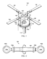
- FIGURE 1 shows an example helicopter rotor assembly 100.
- helicopter rotor assembly 100 includes a drive shaft 110, a drive assembly 120, blades 130, a swashplate 140, and pitch links 150.
- helicopter rotor assembly 100 may include more or fewer components.
- FIGURE 1 does not show components such as a gearbox, a yoke, drive links, drive levers, and other components that may be incorporated into helicopter rotor assembly 100.
- Drive shaft 110 and drive assembly 120 are mechanical components for transmitting torque and/or rotation.
- Drive shaft 110 and drive assembly 120 may represent components of a drive train, which may also include an engine, a transmission, differentials, and the final drive (e.g., blades 130).
- drive shaft 110 receives torque or rotational energy and rotates drive assembly 120. Rotation of drive assembly 120 causes blades 130 to rotate about drive shaft 110.
- Swashplate 140 translates input via helicopter flight controls into motion of blades 130. Because blades 130 are typically spinning when the helicopter is in flight, swashplate 140 may transmit flight controls from the non-rotating fuselage to the rotating drive assembly 120 and/or blades 130.
- swashplate 140 may include a stationary swashplate 140a and a rotating swashplate 140b. Stationary swashplate 140a does not rotate with drive shaft 110, whereas rotating swashplate 140b does rotate with drive shaft 110.
- pitch links 150 connect rotating swashplate 140b to blades 130. In operation, tilting stationary swashplate 140a causes rotating swashplate 140b to tilt, which in turn moves pitch links 150 up and down. Moving pitch links 150 up and down changes the pitch of blades 130.
- tilting swashplate 140 toward the left of the helicopter may cause an upward flapping motion of the blade 90 degrees after the blade reaches maximum lift (on the right hand side if the rotor turns counterclockwise as viewed from above).
- the plane of the rotor appears to be titled to the left with respect to the fuselage, and the helicopter begins a left (counterclockwise) roll as viewed from behind.
- FIGURE 2 shows pitch link 150 of FIGURE 1 .
- pitch link 150 includes a first bearing housing 152a having a first bearing 154a, a second bearing housing 152b having a second bearing 154b, a first jam nut 156a, a second jam nut 156b, and a link 158.
- the overall length of pitch link 150 is adjustable. To adjust the overall length of pitch link 150, one may loosen first jam nut 156a and/or second jam nut 156b and then rotate link 158 to either increase or decrease the length of pitch link 150. Once the length of pitch link 150 is changed, first jam nut 156a and second jam nut 156b may be tightened against link 158.
- the lengths of pitch links 150 are not intended to change during flight.
- An unexpected or unplanned change in length of a pitch link 150 may cause helicopter rotor assembly 100 to become unstable. Changes in length outside the bearing wear tolerances may cause helicopter rotor assembly 100 to endure higher vibrations and oscillatory loads.
- bearings 154a and 154b are monoball sliding elements with a Teflon liner. Bearings such as bearings 154a and 154b may wear out over time due to normal wear and tear as well as environmental factors. For example, bearings 154a and 154b may wear out faster in a place such as Afghanistan where sand may become stuck in bearings 154a and 154b and scrape against the Teflon liner like sandpaper. Accordingly, bearings 154a and 154b may be replaced over time, such as part of a regular maintenance procedure.
- Bearing housings 152a and 152b house bearings 154a and 154b.
- bearing housings In the industry, receptacles located near the end of a pitch link configured to receive bearings are known as bearing housings.
- bearings 154a and 154b are staked into bearing housings 152a and 152b. With a staked-in bearing, a flange of material is deflected to permanently keep the bearing in its housing. Attempting to remove a staked-in bearing from its housing may cause damage to the housing.
- Old bearing housings 152a and 152b may be replaced with new bearing housings 152a and 152b, and new bearing housings 152a and 152b may be secured to link 158 by retightening jam nuts 156a and 156b.
- bearings 154a and 154b are permanently staked in bearing housings 152a and 152b. Replacing bearing housings 152a and 152b, however, may inadvertently cause the length of pitch link 150 to change.
- bearings 154a and 154b may be secured in bearing housings 152a and 152b without staking-in bearings 154a and 154b.
- bearings 154a and 154b may be secured in bearing housings 152a and 152b without staking-in bearings 154a and 154b.
- bearing housings 152a and 152b By securing bearings 154a and 154b in bearing housings 152a and 152b without staking-in bearings 154a and 154b, one may theoretically replace bearings 154a and 154b without moving bearing housings 152a and 152b and/or jam nuts 156a and 156b.
- non-staked solutions may not be suitable for high oscillatory loads typical in rotor systems.
- Certain embodiments provide the capability to replace bearings, such as staked-in bearings, while maintaining the original length of a pitch link. Certain embodiments also provide the capability to replace bearings in a rotor pitch link without requiring a technician to remeasure the length of the rotor pitch link.
- FIGURE 3 shows a pitch link 200 according to one example embodiment.
- pitch link 200 includes a first bearing housing 210a housing a first bearing 220a, a second bearing housing 210b housing a second bearing 220b, a first jam nut 230a, a second jam nut 230b, and links 240, 250a, and 250b.
- links 240 and 250a are coupled together via threads, and first jam nut 230a prevents links 240 and 250a from dethreading.
- Links 240 and 250b are also coupled together via threads, and second jam nut 230b prevents links 240 and 250b from dethreading.
- First bearing housing 210a threads into link 250a along first bearing housing thread 260a.
- Second bearing housing 210b threads into link 250b along second bearing housing thread 260b.
- the overall length of pitch link 200 is adjustable by adjusting the overall combined length of links 240, 250a, and 250b.
- first jam nut 230a and/or second jam nut 230b may be loosen and then rotate link 240 to either increase or decrease the length of pitch link 200.
- first jam nut 230a and second jam nut 230b may be tightened against link 240.
- bearing housings 210a and 210b of pitch link 200 may be removed and replaced without disturbing jam nuts 230a and 230b.
- To replace bearing housings 210a and 210b one may unscrew bearing housings 210a and 210b from bearing housing threads 260a and 260b. Old bearing housings 210a and 210b may be replaced with new bearing housings 210a and 210b, which may be inserted along bearing housing threads 260a and 260b.
- bearing housings 210a and 210b may be replaced without disturbing the overall length of pitch link 200.
- FIGURE 4A shows a plan view of the bearing housing 210a of FIGURE 3.
- FIGURE 4B shows a cross-section view of the bearing housing 210a of FIGURE 3 (with the jam nut not shown for purposes of clarity).
- FIGURE 4A shows bearing housing 210a having first bearing housing thread 260a.
- Link 250a has an opening (not shown) for receiving first bearing housing thread 260a.
- an old first bearing housing 210a may be replaced with a new first bearing housing 210a.
- the new first bearing housing 210a would have a similar thread for screwing into link 250a.
- old and new first bearing housings 210a would have threads with approximately the same threads-per-inch.
- the new first bearing housing 210a would need to have the same distance to the bearing to prevent changing the location of the bearing.
- the new first bearing housing 210a may have the same Distance D and/or Distance E, as shown in FIGURE 4A .
- Each first bearing housing 210a should be installed in the same position and clocking. If the old first bearing housing 210a and the new first bearing housing 210a are not clocked at the same angle, then the clocking of the new first bearing housing 210a may not leave sufficient clearance to prevent impinging on other rotor system components (which could cause damage). In addition, if the old first bearing housing 210a is not clocked at the same angle as the new first bearing housing 210a, then the new bearing 220a will not be oriented in the same direction as the old bearing 220a. In some circumstances, this could result in the new bearing 220a not being aligned to mount on its corresponding post attached to drive assembly 120, blade 130, and/or swashplate 140.
- certain embodiments provide the capability to provide fixed-index threads for each first bearing housing 210a.
- the beginning of thread 260a is indexed with respect to the face of first bearing housing 210a.
- thread 260a begins at an angle 265a relative to the face of first bearing housing 210a.
- both old and new first bearing housings 210a have a thread 260a that begins at the tip at the same angle 265a relative to the face of first bearing housing 210a.
- thread 260a may end at the face of first bearing housing 210a at the same angle instead of and/or in addition to beginning at the tip at the same angle. For example, if each first bearing housing 210a has the same Distance E, as shown in FIGURE 4A , then each thread 260a may end at the face of the first bearing housing 210a at the same angle.
Landscapes
- Engineering & Computer Science (AREA)
- Mechanical Engineering (AREA)
- General Engineering & Computer Science (AREA)
- Aviation & Aerospace Engineering (AREA)
- Mounting Of Bearings Or Others (AREA)
- Transmission Devices (AREA)
- Sliding-Contact Bearings (AREA)
Abstract
Description
- Pursuant to 35 U.S.C. § 119 (e), this application claims priority to United States Provisional Patent Application Serial No.
61/580,824 61/580,824 - This invention relates generally to rotor systems, and more particularly, to an adjustable pitch link.
- A helicopter may include one or more rotor systems. One example of a helicopter rotor system is a main rotor system. A main rotor system may generate aerodynamic lift to support the weight of the helicopter in flight and thrust to counteract aerodynamic drag and move the helicopter in forward flight. Another example of a helicopter rotor system is a tail rotor system. A tail rotor system may generate thrust in the same direction as the main rotor system's rotation to counter the torque effect created by the main rotor system. A rotor system may include one or more pitch links to rotate, deflect, and/or adjust rotor blades.
- According to one embodiment, a pitch link comprises a first link, a second link coupled to a first end of the first link, a third link coupled to a second end of the first link opposite the first end, and a first bearing housing having a first bearing and a second bearing housing having a second bearing. The first bearing housing is removably coupled to the second link. The second link separates the first bearing housing from the first link. The second bearing housing is removably coupled to the third link. The third link separates the second bearing housing from the first link. Particular embodiments of the present disclosure may provide one or more technical advantages. A technical advantage of one embodiment may include the capability to replace bearings in a rotor pitch link without disturbing the length of the rotor pitch link. A technical advantage of one embodiment may also include the capability to replace bearings in a rotor pitch link without requiring a technician to remeasure the length of the rotor pitch link. A technical advantage of one embodiment may also include the capability to provide a rotor pitch link with replaceable bearings without compromising strength of the bearings.
- Certain embodiments of the present disclosure may include some, all, or none of the above advantages. One or more other technical advantages may be readily apparent to those skilled in the art from the figures, descriptions, and claims included herein.
- To provide a more complete understanding of the present invention and the features and advantages thereof, reference is made to the following description taken in conjunction with the accompanying drawings, in which:
-
FIGURE 1 shows an example helicopter rotor assembly; -
FIGURE 2 shows the pitch link ofFIGURE 1 ; -
FIGURE 3 shows a pitch link according to one example embodiment; -
FIGURE 4A shows a plan view of the first bearing housing ofFIGURE 3 ; and -
FIGURE 4B shows a cross-section view of the first bearing housing ofFIGURE 3 . -
FIGURE 1 shows an examplehelicopter rotor assembly 100. In this example,helicopter rotor assembly 100 includes adrive shaft 110, adrive assembly 120,blades 130, aswashplate 140, andpitch links 150. In some examples,helicopter rotor assembly 100 may include more or fewer components. For example,FIGURE 1 does not show components such as a gearbox, a yoke, drive links, drive levers, and other components that may be incorporated intohelicopter rotor assembly 100. -
Drive shaft 110 anddrive assembly 120 are mechanical components for transmitting torque and/or rotation.Drive shaft 110 anddrive assembly 120 may represent components of a drive train, which may also include an engine, a transmission, differentials, and the final drive (e.g., blades 130). In operation,drive shaft 110 receives torque or rotational energy and rotatesdrive assembly 120. Rotation ofdrive assembly 120 causesblades 130 to rotate aboutdrive shaft 110. - Swashplate 140 translates input via helicopter flight controls into motion of
blades 130. Becauseblades 130 are typically spinning when the helicopter is in flight,swashplate 140 may transmit flight controls from the non-rotating fuselage to the rotatingdrive assembly 120 and/orblades 130. - In some examples,
swashplate 140 may include astationary swashplate 140a and a rotatingswashplate 140b.Stationary swashplate 140a does not rotate withdrive shaft 110, whereas rotatingswashplate 140b does rotate withdrive shaft 110. In the example ofFIGURE 1 ,pitch links 150 connect rotatingswashplate 140b toblades 130. In operation, tiltingstationary swashplate 140a causes rotatingswashplate 140b to tilt, which in turn movespitch links 150 up and down. Movingpitch links 150 up and down changes the pitch ofblades 130. For example, tiltingswashplate 140 toward the left of the helicopter may cause an upward flapping motion of the blade 90 degrees after the blade reaches maximum lift (on the right hand side if the rotor turns counterclockwise as viewed from above). In this example, the plane of the rotor appears to be titled to the left with respect to the fuselage, and the helicopter begins a left (counterclockwise) roll as viewed from behind. -
FIGURE 2 shows pitch link 150 ofFIGURE 1 . In this example,pitch link 150 includes a first bearinghousing 152a having a first bearing 154a, a second bearinghousing 152b having a second bearing 154b, afirst jam nut 156a, asecond jam nut 156b, and alink 158. - In this example, the overall length of
pitch link 150 is adjustable. To adjust the overall length ofpitch link 150, one may loosenfirst jam nut 156a and/orsecond jam nut 156b and then rotatelink 158 to either increase or decrease the length ofpitch link 150. Once the length ofpitch link 150 is changed,first jam nut 156a andsecond jam nut 156b may be tightened againstlink 158. - In these examples, the lengths of
pitch links 150 are not intended to change during flight. An unexpected or unplanned change in length of apitch link 150 may causehelicopter rotor assembly 100 to become unstable. Changes in length outside the bearing wear tolerances may causehelicopter rotor assembly 100 to endure higher vibrations and oscillatory loads. - In the example of
FIGURE 2 ,bearings bearings bearings bearings bearings - Bearing
housings 152b house bearings example pitch link 150 ofFIGURE 2 ,bearings housings - To replace staked-in
bearings pitch link 150, one may loosenjam nuts housings 152a and 152b.Old bearing housings new bearing housings new bearing housings jam nuts - As stated previously,
bearings housings bearing housings pitch link 150 to change. - Other mechanisms are also available to replace
bearings bearings housings bearings bearings housings bearings bearings bearing housings jam nuts - Certain embodiments provide the capability to replace bearings, such as staked-in bearings, while maintaining the original length of a pitch link. Certain embodiments also provide the capability to replace bearings in a rotor pitch link without requiring a technician to remeasure the length of the rotor pitch link.
-
FIGURE 3 shows apitch link 200 according to one example embodiment. In this example,pitch link 200 includes afirst bearing housing 210a housing afirst bearing 220a, asecond bearing housing 210b housing asecond bearing 220b, afirst jam nut 230a, asecond jam nut 230b, and links 240, 250a, and 250b. - In this example,
links first jam nut 230a preventslinks Links second jam nut 230b preventslinks housing 210a threads intolink 250a along first bearinghousing thread 260a. Second bearinghousing 210b threads intolink 250b along second bearinghousing thread 260b. - In this example, the overall length of
pitch link 200 is adjustable by adjusting the overall combined length oflinks links first jam nut 230a and/orsecond jam nut 230b and then rotatelink 240 to either increase or decrease the length ofpitch link 200. Once the length ofpitch link 200 is changed,first jam nut 230a andsecond jam nut 230b may be tightened againstlink 240. - Unlike the
example pitch link 150 ofFIGURE 2 , however, bearinghousings pitch link 200 may be removed and replaced without disturbing jam nuts 230a and 230b. To replacebearing housings housings housing threads 260a and 260b.Old bearing housings new bearing housings housing threads link 250a between first bearinghousing 210a andadjustment link 240, and by providinglink 250b between second bearinghousing 210b andadjustment link 240, bearinghousings pitch link 200. -
FIGURE 4A shows a plan view of the bearinghousing 210a ofFIGURE 3. FIGURE 4B shows a cross-section view of the bearinghousing 210a ofFIGURE 3 (with the jam nut not shown for purposes of clarity).FIGURE 4A shows bearinghousing 210a having first bearinghousing thread 260a.Link 250a has an opening (not shown) for receiving first bearinghousing thread 260a. - As explained previously, an old
first bearing housing 210a may be replaced with a newfirst bearing housing 210a. The newfirst bearing housing 210a would have a similar thread for screwing intolink 250a. For example, old and newfirst bearing housings 210a would have threads with approximately the same threads-per-inch. In addition, the newfirst bearing housing 210a would need to have the same distance to the bearing to prevent changing the location of the bearing. For example, the newfirst bearing housing 210a may have the same Distance D and/or Distance E, as shown inFIGURE 4A . - In some circumstances, however, having the same threads-per-inch and same distance to the bearing may not be sufficient. Each first bearing
housing 210a should be installed in the same position and clocking. If the oldfirst bearing housing 210a and the newfirst bearing housing 210a are not clocked at the same angle, then the clocking of the newfirst bearing housing 210a may not leave sufficient clearance to prevent impinging on other rotor system components (which could cause damage). In addition, if the oldfirst bearing housing 210a is not clocked at the same angle as the newfirst bearing housing 210a, then thenew bearing 220a will not be oriented in the same direction as theold bearing 220a. In some circumstances, this could result in thenew bearing 220a not being aligned to mount on its corresponding post attached to driveassembly 120,blade 130, and/orswashplate 140. - Accordingly, certain embodiments provide the capability to provide fixed-index threads for each first bearing
housing 210a. As shown inFIGURE 4B , the beginning ofthread 260a is indexed with respect to the face offirst bearing housing 210a. In the example ofFIGURE 4B ,thread 260a begins at anangle 265a relative to the face offirst bearing housing 210a. By maintaining aconsistent angle 265a for every first bearinghousing 210a produced, each first bearinghousing 210a may be used interchangeably. - In the example of
FIGURE 4B , both old and newfirst bearing housings 210a have athread 260a that begins at the tip at thesame angle 265a relative to the face offirst bearing housing 210a. In another example embodiment,thread 260a may end at the face offirst bearing housing 210a at the same angle instead of and/or in addition to beginning at the tip at the same angle. For example, if each first bearinghousing 210a has the same Distance E, as shown inFIGURE 4A , then eachthread 260a may end at the face of thefirst bearing housing 210a at the same angle. - Modifications, additions, or omissions may be made to the systems and apparatuses described herein without departing from the scope of the invention. The components of the systems and apparatuses may be integrated or separated. Moreover, the operations of the systems and apparatuses may be performed by more, fewer, or other components. The methods may include more, fewer, or other steps. Additionally, steps may be performed in any suitable order.
- Although several embodiments have been illustrated and described in detail, it will be recognized that substitutions and alterations are possible without departing from the spirit and scope of the present invention, as defined by the appended claims.
- To aid the Patent Office, and any readers of any patent issued on this application in interpreting the claims appended hereto, applicants wish to note that they do not intend any of the appended claims to invoke paragraph 6 of 35 U.S.C. § 112 as it exists on the date of filing hereof unless the words "means for" or "step for" are explicitly used in the particular claim.
Claims (15)
- A pitch link, comprising:a link assembly having an overall adjustable length, the link assembly comprising:a first link;a second link coupled to a first end of the first link; anda third link coupled to a second end of the first link opposite the first end;a first bearing housing having a first bearing, the first bearing housing removably coupled to the second link, the second link separating the first bearing housing from the first link; anda second bearing housing having a second bearing, the second bearing housing removably coupled to the third link, the third link separating the second bearing housing from the first link.
- A rotorcraft comprising:a body;a power train coupled to the body and comprising a power source and a drive shaft coupled to the power source;a hub coupled to the drive shaft;a rotor blade coupled to the hub;a swashplate positioned about the drive shaft; and
a pitch link coupled between the swashplate and the hub corresponding to the rotor blade, the pitch link comprising a pitch link according to claim 1. - A rotorcraft, comprising:a body;a power train coupled to the body and comprising a power source and a drive shaft coupled to the power source;a hub coupled to the drive shaft;a rotor blade coupled to the hub;a swashplate positioned about the drive shaft; anda pitch link coupled between the swashplate and the hub corresponding to the rotor blade, the pitch link comprising:a link assembly having an overall adjustable length, the link assembly comprising a first link, a second link coupled to a first end of the first link, and a third link coupled to a second end of the first link opposite the first end;a first bearing housing having a first bearing, the first bearing housing removably coupled to the second link, the second link separating the first bearing housing from the first link; anda second bearing housing having a second bearing, the second bearing housing removably coupled to the third link, the third link separating the second bearing housing from the first link.
- The pitch link of claim 1 or the rotorcraft of claim 2 or claim 3, further comprising:a first jam nut coupling the first link to the second link; anda second jam nut coupling the first link to the third link.
- The pitch link of claim 4 or the rotorcraft of claim 4, wherein the overall adjustable length is adjustable by adjusting at least one of the first jam nut and the second jam nut.
- The pitch link or rotorcraft of any preceding claim, wherein the second link separates the first bearing housing from the first link such that removal of the first bearing housing does not alter the overall adjustable length.
- The pitch link or rotorcraft of any preceding claim, wherein the first bearing housing threads into the second link.
- The pitch link or rotorcraft of any preceding claim, further comprising a replacement bearing housing, wherein the first bearing housing and the replacement bearing housing substantially share a common fixed-index thread.
- The pitch link or rotorcraft of claim 7 or of claim 8, wherein the first bearing housing comprises a first thread, the first thread having a first end that begins at a first position relative to a first point of reference local to the first bearing housing, the first thread configured to thread into a receiving portion of the second link, the pitch link or rotorcraft further comprising:a replacement bearing housing for the first bearing housing, the replacement bearing housing having a first bearing and a thread substantially similar to the first thread such that the thread of the replacement bearing housing substantially begins at the first position relative to the first point of reference local to the replacement bearing housing, the thread of the replacement bearing configured to thread into the receiving portion of the second link.
- A method of replacing a bearing in an aircraft pitch link, the aircraft pitch link comprising a link assembly having an overall adjustable length, the link assembly comprising a first link, a second link coupled to a first end of the first link, and a third link coupled to a second end of the first link opposite the first end, the method comprising:removing a first bearing housing from the second link of the aircraft pitch link, the first bearing housing having a first bearing; andcoupling a first replacement bearing housing to the second link of the aircraft pitch link, the first replacement bearing housing having a first replacement bearing.
- The method of claim 10, further comprising:removing a second bearing housing from the third link of the aircraft pitch link, the second bearing housing having a second bearing; andcoupling a second replacement bearing housing to the third link of the aircraft pitch link, the second replacement bearing housing having a second replacement bearing.
- The method of claim 10 or of claim 11, the aircraft pitch link further comprising a first jam nut coupling the first link to the second link, the method further comprising:adjusting the overall length by adjusting a position of the first jam nut.
- The method of claim 10 or of claim 11 or of claim 12, wherein the second link separates the first bearing housing from the first link such that removal of the first bearing housing does not alter the overall adjustable length.
- The method of claim 10 or of any of claims 11 to 13, wherein coupling the first replacement bearing housing to the second link comprises threading the first replacement bearing housing into the second link.
- The method of claim 10 or of any of claims 11 to 14, wherein the first bearing housing and the first replacement bearing housing substantially share a common fixed-index thread.
Applications Claiming Priority (2)
| Application Number | Priority Date | Filing Date | Title |
|---|---|---|---|
| US201161580824P | 2011-12-28 | 2011-12-28 | |
| US13/669,212 US10377477B2 (en) | 2011-12-28 | 2012-11-05 | Adjustable pitch link |
Publications (2)
| Publication Number | Publication Date |
|---|---|
| EP2610168A1 true EP2610168A1 (en) | 2013-07-03 |
| EP2610168B1 EP2610168B1 (en) | 2015-09-30 |
Family
ID=47263140
Family Applications (1)
| Application Number | Title | Priority Date | Filing Date |
|---|---|---|---|
| EP12194301.3A Active EP2610168B1 (en) | 2011-12-28 | 2012-11-26 | Adjustable pitch link |
Country Status (3)
| Country | Link |
|---|---|
| US (1) | US10377477B2 (en) |
| EP (1) | EP2610168B1 (en) |
| CA (1) | CA2800439C (en) |
Cited By (3)
| Publication number | Priority date | Publication date | Assignee | Title |
|---|---|---|---|---|
| WO2015017101A1 (en) | 2013-07-29 | 2015-02-05 | Sikorsky Aircraft Corporation | Adjustable scissor control link |
| EP2853756A1 (en) * | 2013-09-30 | 2015-04-01 | Bell Helicopter Textron Inc. | System and method of monitoring wear in a bearing |
| EP3296198A1 (en) | 2016-09-15 | 2018-03-21 | AIRBUS HELICOPTERS DEUTSCHLAND GmbH | Adjustment of track and balance of a multi-blade rotor |
Families Citing this family (11)
| Publication number | Priority date | Publication date | Assignee | Title |
|---|---|---|---|---|
| US9010679B2 (en) * | 2012-06-26 | 2015-04-21 | Bell Helicopter Textron Inc. | Hybrid spherical and thrust bearing |
| US9840325B2 (en) * | 2012-06-26 | 2017-12-12 | Bell Helicopter Textron Inc. | Dual series pitch link bearing |
| US9657816B2 (en) * | 2013-11-01 | 2017-05-23 | Bell Helicopter Textron Inc. | Drive link for tiltrotor rotor system |
| US20170341733A1 (en) * | 2016-05-27 | 2017-11-30 | Sikorsky Aircraft Corporation | Rotor head for prop-rotor |
| CN107377980B (en) * | 2017-08-22 | 2024-04-02 | 山西东睦华晟粉末冶金有限公司 | Threaded connection connecting rod body for new energy automobile and preparation method thereof |
| US11535370B2 (en) | 2019-10-11 | 2022-12-27 | Textron Innovations Inc. | Over-centering blade lock |
| US11142300B2 (en) | 2019-10-17 | 2021-10-12 | Bell Textron Inc. | Length adjustable link |
| CN113494513B (en) * | 2020-04-07 | 2022-08-19 | 广州汽车集团股份有限公司 | Length-variable connecting rod device |
| CN111301674B (en) * | 2020-04-14 | 2024-11-05 | 中国人民解放军32180部队 | Improved swash plate |
| US11912403B2 (en) | 2021-03-20 | 2024-02-27 | Textron Innovations Inc. | Pitch link centering tool |
| CA3149115A1 (en) * | 2021-03-30 | 2022-09-30 | The Boeing Company | Tie-rod with a swivel end |
Citations (5)
| Publication number | Priority date | Publication date | Assignee | Title |
|---|---|---|---|---|
| US3866650A (en) * | 1970-12-03 | 1975-02-18 | Lockheed Aircraft Corp | Internal locking device |
| US6659399B1 (en) * | 2002-11-25 | 2003-12-09 | The Boeing Company | Compact linear split sleeves for accurate rigging in confined space |
| US20050178215A1 (en) * | 2004-02-18 | 2005-08-18 | Edward Mayer | Linkage and sensor assembly |
| US7524169B2 (en) * | 2006-01-17 | 2009-04-28 | The Boeing Company | Helicopter pitch link with accessible adjustment features |
| EP2067697A1 (en) * | 2007-12-07 | 2009-06-10 | SKF Aerospace France | Connecting rod for aeronautical construction and mechanism comprising such a connecting rod |
Family Cites Families (23)
| Publication number | Priority date | Publication date | Assignee | Title |
|---|---|---|---|---|
| US141191A (en) | 1873-07-22 | Improvement in connecting-rods | ||
| US2102325A (en) * | 1936-06-09 | 1937-12-14 | Boeing Aircraft Co | Airplane control rod and method of making the same |
| US3217240A (en) * | 1961-06-07 | 1965-11-09 | Kaman Aircraft Corp | Movable core transformer control device |
| US3415324A (en) * | 1967-05-15 | 1968-12-10 | Lockheed Aircraft Corp | Micrometer pitch link |
| US3736010A (en) * | 1970-12-03 | 1973-05-29 | Lockheed Aircraft Corp | Pitch link assembly and locking device therewith |
| US3786695A (en) * | 1972-04-28 | 1974-01-22 | Boeing Co | Redundant pitch link |
| US5026254A (en) | 1989-10-13 | 1991-06-25 | Bell Helicopter Textron Inc. | Calibrated pitch change link |
| US5174677A (en) * | 1991-08-30 | 1992-12-29 | The United States Of America As Represented By The Department Of The Army | Main rotor pitch control rod assembly with passive locking feature |
| US5727926A (en) * | 1992-11-25 | 1998-03-17 | Kawasaki Jukogyo Kabushiki Kaisha | Pitch link for rotary wing aircraft and automatic adjuster thereof |
| JP2577170B2 (en) * | 1992-11-25 | 1997-01-29 | 川崎重工業株式会社 | Pitch link for rotary wing aircraft and automatic adjustment device thereof |
| US5454153A (en) | 1993-08-27 | 1995-10-03 | Noel; Hector | Adjustable assembly for use in the repair or replacement of a pitch change link or rod end of critical predetermined length |
| US5431540A (en) * | 1993-12-14 | 1995-07-11 | United Technologies Corporation | Main rotor pitch control rod subassembly |
| US5505106A (en) * | 1994-10-31 | 1996-04-09 | Chrysler Corporation | Adjustable tie-rod assembly for a motor vehicle |
| US5460487A (en) * | 1994-11-09 | 1995-10-24 | United Technologies Corporation | Pitch adjustment assembly for bearingless main rotors |
| DE10125178B4 (en) * | 2001-05-23 | 2010-01-28 | Zf Luftfahrttechnik Gmbh | Individual rotor blade control device |
| US6953313B2 (en) * | 2003-06-26 | 2005-10-11 | Gordon Tylosky | Self-locking linear adjustment mechanism |
| DE202004016321U1 (en) | 2004-10-20 | 2005-03-10 | Trigum-Engineering Gmbh | Train-push rod |
| US7207854B1 (en) * | 2005-10-13 | 2007-04-24 | Brunswick Corporation | Connection system for two or more marine propulsion devices |
| US8230718B2 (en) | 2007-12-21 | 2012-07-31 | Walin Tool, LLC | Apparatus and method for detecting wear in rotor pitch link bearings |
| US7788993B2 (en) * | 2008-03-01 | 2010-09-07 | The Boeing Company | Tie rod assembly |
| US8425270B2 (en) * | 2011-01-18 | 2013-04-23 | Marine Canada Acquisition Inc. | Length-adjustable tie bar for marine engines |
| DE102012206755B4 (en) * | 2012-04-25 | 2022-11-24 | Zf Friedrichshafen Ag | control rod arrangement |
| DE202012103224U1 (en) * | 2012-08-26 | 2012-09-14 | Ro-Ra Produktions Gmbh | Train-push rod |
-
2012
- 2012-11-05 US US13/669,212 patent/US10377477B2/en active Active
- 2012-11-26 EP EP12194301.3A patent/EP2610168B1/en active Active
- 2012-12-20 CA CA2800439A patent/CA2800439C/en active Active
Patent Citations (5)
| Publication number | Priority date | Publication date | Assignee | Title |
|---|---|---|---|---|
| US3866650A (en) * | 1970-12-03 | 1975-02-18 | Lockheed Aircraft Corp | Internal locking device |
| US6659399B1 (en) * | 2002-11-25 | 2003-12-09 | The Boeing Company | Compact linear split sleeves for accurate rigging in confined space |
| US20050178215A1 (en) * | 2004-02-18 | 2005-08-18 | Edward Mayer | Linkage and sensor assembly |
| US7524169B2 (en) * | 2006-01-17 | 2009-04-28 | The Boeing Company | Helicopter pitch link with accessible adjustment features |
| EP2067697A1 (en) * | 2007-12-07 | 2009-06-10 | SKF Aerospace France | Connecting rod for aeronautical construction and mechanism comprising such a connecting rod |
Cited By (6)
| Publication number | Priority date | Publication date | Assignee | Title |
|---|---|---|---|---|
| WO2015017101A1 (en) | 2013-07-29 | 2015-02-05 | Sikorsky Aircraft Corporation | Adjustable scissor control link |
| EP3027504A4 (en) * | 2013-07-29 | 2017-04-12 | Sikorsky Aircraft Corporation | Adjustable scissor control link |
| EP2853756A1 (en) * | 2013-09-30 | 2015-04-01 | Bell Helicopter Textron Inc. | System and method of monitoring wear in a bearing |
| US9157474B2 (en) | 2013-09-30 | 2015-10-13 | Bell Helicopter Textron Inc. | System and method of monitoring wear in a bearing |
| EP3296198A1 (en) | 2016-09-15 | 2018-03-21 | AIRBUS HELICOPTERS DEUTSCHLAND GmbH | Adjustment of track and balance of a multi-blade rotor |
| US10870484B2 (en) | 2016-09-15 | 2020-12-22 | Airbus Helicopters Deutschland GmbH | Adjustment of track and balance of a multi-blade rotor |
Also Published As
| Publication number | Publication date |
|---|---|
| US20130168492A1 (en) | 2013-07-04 |
| CA2800439C (en) | 2016-03-22 |
| US10377477B2 (en) | 2019-08-13 |
| EP2610168B1 (en) | 2015-09-30 |
| CA2800439A1 (en) | 2013-06-28 |
Similar Documents
| Publication | Publication Date | Title |
|---|---|---|
| EP2610168B1 (en) | Adjustable pitch link | |
| US9657582B2 (en) | Gimbaled tail rotor hub with spherical elastomeric centrifugal force bearing for blade retention and pitch change articulation | |
| EP2730505B1 (en) | Preventing rotation of a fixed ring of a swashplate | |
| US10220937B2 (en) | Multi-slice rotary electromechanical actuator | |
| US10745122B2 (en) | Redundant helicopter pitch change shaft system | |
| US20180266251A1 (en) | Quick release rotor attachment systems and methods | |
| EP2730503B1 (en) | Flexbeam rotor attachment to rotor blade | |
| EP2602186A1 (en) | Preventing rotation of a fixed ring of a swashplate | |
| EP2687441B1 (en) | Elastomeric bearing housing and mating grip for helicopter rotor system | |
| US4681511A (en) | Low vibration helicopter rotor | |
| DK2772432T3 (en) | Rotorfly pitch beam attachment with anti-rotation plate design | |
| US20180281937A1 (en) | Rigid rotor head with tension torsion (tt) strap retention | |
| US10745117B2 (en) | Radially compliant quill shaft | |
| EP2660150B1 (en) | Multi-element rotor blade | |
| EP4223635A1 (en) | Compact propeller blade retention assembly | |
| US11999472B2 (en) | Rotor blade non-counterbored retention assembly via a sliding clamped bushing | |
| US11345468B2 (en) | Clevis assembly with bearing device in operable communication with a translating element, and fail-safe tail rotor system including the same | |
| US10654566B2 (en) | Integrated main rotor hub and shaft | |
| EP4635844A1 (en) | Low drag airfoil |
Legal Events
| Date | Code | Title | Description |
|---|---|---|---|
| PUAI | Public reference made under article 153(3) epc to a published international application that has entered the european phase |
Free format text: ORIGINAL CODE: 0009012 |
|
| 17P | Request for examination filed |
Effective date: 20121126 |
|
| AK | Designated contracting states |
Kind code of ref document: A1 Designated state(s): AL AT BE BG CH CY CZ DE DK EE ES FI FR GB GR HR HU IE IS IT LI LT LU LV MC MK MT NL NO PL PT RO RS SE SI SK SM TR |
|
| AX | Request for extension of the european patent |
Extension state: BA ME |
|
| 17Q | First examination report despatched |
Effective date: 20130828 |
|
| REG | Reference to a national code |
Ref country code: DE Ref legal event code: R079 Ref document number: 602012011076 Country of ref document: DE Free format text: PREVIOUS MAIN CLASS: B64C0013300000 Ipc: B64C0027605000 |
|
| RIC1 | Information provided on ipc code assigned before grant |
Ipc: B64C 27/605 20060101AFI20150424BHEP Ipc: B64C 27/59 20060101ALI20150424BHEP Ipc: F16C 7/06 20060101ALI20150424BHEP |
|
| GRAP | Despatch of communication of intention to grant a patent |
Free format text: ORIGINAL CODE: EPIDOSNIGR1 |
|
| INTG | Intention to grant announced |
Effective date: 20150713 |
|
| GRAS | Grant fee paid |
Free format text: ORIGINAL CODE: EPIDOSNIGR3 |
|
| GRAA | (expected) grant |
Free format text: ORIGINAL CODE: 0009210 |
|
| AK | Designated contracting states |
Kind code of ref document: B1 Designated state(s): AL AT BE BG CH CY CZ DE DK EE ES FI FR GB GR HR HU IE IS IT LI LT LU LV MC MK MT NL NO PL PT RO RS SE SI SK SM TR |
|
| REG | Reference to a national code |
Ref country code: CH Ref legal event code: EP Ref country code: GB Ref legal event code: FG4D |
|
| REG | Reference to a national code |
Ref country code: AT Ref legal event code: REF Ref document number: 752223 Country of ref document: AT Kind code of ref document: T Effective date: 20151015 |
|
| REG | Reference to a national code |
Ref country code: IE Ref legal event code: FG4D |
|
| REG | Reference to a national code |
Ref country code: DE Ref legal event code: R096 Ref document number: 602012011076 Country of ref document: DE |
|
| REG | Reference to a national code |
Ref country code: FR Ref legal event code: PLFP Year of fee payment: 4 |
|
| PG25 | Lapsed in a contracting state [announced via postgrant information from national office to epo] |
Ref country code: LV Free format text: LAPSE BECAUSE OF FAILURE TO SUBMIT A TRANSLATION OF THE DESCRIPTION OR TO PAY THE FEE WITHIN THE PRESCRIBED TIME-LIMIT Effective date: 20150930 Ref country code: LT Free format text: LAPSE BECAUSE OF FAILURE TO SUBMIT A TRANSLATION OF THE DESCRIPTION OR TO PAY THE FEE WITHIN THE PRESCRIBED TIME-LIMIT Effective date: 20150930 Ref country code: NO Free format text: LAPSE BECAUSE OF FAILURE TO SUBMIT A TRANSLATION OF THE DESCRIPTION OR TO PAY THE FEE WITHIN THE PRESCRIBED TIME-LIMIT Effective date: 20151230 Ref country code: GR Free format text: LAPSE BECAUSE OF FAILURE TO SUBMIT A TRANSLATION OF THE DESCRIPTION OR TO PAY THE FEE WITHIN THE PRESCRIBED TIME-LIMIT Effective date: 20151231 Ref country code: FI Free format text: LAPSE BECAUSE OF FAILURE TO SUBMIT A TRANSLATION OF THE DESCRIPTION OR TO PAY THE FEE WITHIN THE PRESCRIBED TIME-LIMIT Effective date: 20150930 |
|
| REG | Reference to a national code |
Ref country code: NL Ref legal event code: MP Effective date: 20150930 |
|
| REG | Reference to a national code |
Ref country code: LT Ref legal event code: MG4D |
|
| REG | Reference to a national code |
Ref country code: AT Ref legal event code: MK05 Ref document number: 752223 Country of ref document: AT Kind code of ref document: T Effective date: 20150930 |
|
| PG25 | Lapsed in a contracting state [announced via postgrant information from national office to epo] |
Ref country code: SE Free format text: LAPSE BECAUSE OF FAILURE TO SUBMIT A TRANSLATION OF THE DESCRIPTION OR TO PAY THE FEE WITHIN THE PRESCRIBED TIME-LIMIT Effective date: 20150930 Ref country code: HR Free format text: LAPSE BECAUSE OF FAILURE TO SUBMIT A TRANSLATION OF THE DESCRIPTION OR TO PAY THE FEE WITHIN THE PRESCRIBED TIME-LIMIT Effective date: 20150930 Ref country code: RS Free format text: LAPSE BECAUSE OF FAILURE TO SUBMIT A TRANSLATION OF THE DESCRIPTION OR TO PAY THE FEE WITHIN THE PRESCRIBED TIME-LIMIT Effective date: 20150930 |
|
| PG25 | Lapsed in a contracting state [announced via postgrant information from national office to epo] |
Ref country code: SK Free format text: LAPSE BECAUSE OF FAILURE TO SUBMIT A TRANSLATION OF THE DESCRIPTION OR TO PAY THE FEE WITHIN THE PRESCRIBED TIME-LIMIT Effective date: 20150930 Ref country code: EE Free format text: LAPSE BECAUSE OF FAILURE TO SUBMIT A TRANSLATION OF THE DESCRIPTION OR TO PAY THE FEE WITHIN THE PRESCRIBED TIME-LIMIT Effective date: 20150930 Ref country code: NL Free format text: LAPSE BECAUSE OF FAILURE TO SUBMIT A TRANSLATION OF THE DESCRIPTION OR TO PAY THE FEE WITHIN THE PRESCRIBED TIME-LIMIT Effective date: 20150930 Ref country code: ES Free format text: LAPSE BECAUSE OF FAILURE TO SUBMIT A TRANSLATION OF THE DESCRIPTION OR TO PAY THE FEE WITHIN THE PRESCRIBED TIME-LIMIT Effective date: 20150930 Ref country code: IS Free format text: LAPSE BECAUSE OF FAILURE TO SUBMIT A TRANSLATION OF THE DESCRIPTION OR TO PAY THE FEE WITHIN THE PRESCRIBED TIME-LIMIT Effective date: 20160130 Ref country code: CZ Free format text: LAPSE BECAUSE OF FAILURE TO SUBMIT A TRANSLATION OF THE DESCRIPTION OR TO PAY THE FEE WITHIN THE PRESCRIBED TIME-LIMIT Effective date: 20150930 |
|
| PG25 | Lapsed in a contracting state [announced via postgrant information from national office to epo] |
Ref country code: PL Free format text: LAPSE BECAUSE OF FAILURE TO SUBMIT A TRANSLATION OF THE DESCRIPTION OR TO PAY THE FEE WITHIN THE PRESCRIBED TIME-LIMIT Effective date: 20150930 Ref country code: PT Free format text: LAPSE BECAUSE OF FAILURE TO SUBMIT A TRANSLATION OF THE DESCRIPTION OR TO PAY THE FEE WITHIN THE PRESCRIBED TIME-LIMIT Effective date: 20160201 Ref country code: AT Free format text: LAPSE BECAUSE OF FAILURE TO SUBMIT A TRANSLATION OF THE DESCRIPTION OR TO PAY THE FEE WITHIN THE PRESCRIBED TIME-LIMIT Effective date: 20150930 Ref country code: RO Free format text: LAPSE BECAUSE OF FAILURE TO SUBMIT A TRANSLATION OF THE DESCRIPTION OR TO PAY THE FEE WITHIN THE PRESCRIBED TIME-LIMIT Effective date: 20150930 |
|
| PG25 | Lapsed in a contracting state [announced via postgrant information from national office to epo] |
Ref country code: LU Free format text: LAPSE BECAUSE OF FAILURE TO SUBMIT A TRANSLATION OF THE DESCRIPTION OR TO PAY THE FEE WITHIN THE PRESCRIBED TIME-LIMIT Effective date: 20151126 Ref country code: MC Free format text: LAPSE BECAUSE OF FAILURE TO SUBMIT A TRANSLATION OF THE DESCRIPTION OR TO PAY THE FEE WITHIN THE PRESCRIBED TIME-LIMIT Effective date: 20150930 |
|
| REG | Reference to a national code |
Ref country code: CH Ref legal event code: PL |
|
| REG | Reference to a national code |
Ref country code: DE Ref legal event code: R097 Ref document number: 602012011076 Country of ref document: DE |
|
| PG25 | Lapsed in a contracting state [announced via postgrant information from national office to epo] |
Ref country code: CH Free format text: LAPSE BECAUSE OF NON-PAYMENT OF DUE FEES Effective date: 20151130 Ref country code: LI Free format text: LAPSE BECAUSE OF NON-PAYMENT OF DUE FEES Effective date: 20151130 |
|
| PLBE | No opposition filed within time limit |
Free format text: ORIGINAL CODE: 0009261 |
|
| STAA | Information on the status of an ep patent application or granted ep patent |
Free format text: STATUS: NO OPPOSITION FILED WITHIN TIME LIMIT |
|
| REG | Reference to a national code |
Ref country code: IE Ref legal event code: MM4A |
|
| PG25 | Lapsed in a contracting state [announced via postgrant information from national office to epo] |
Ref country code: DK Free format text: LAPSE BECAUSE OF FAILURE TO SUBMIT A TRANSLATION OF THE DESCRIPTION OR TO PAY THE FEE WITHIN THE PRESCRIBED TIME-LIMIT Effective date: 20150930 |
|
| 26N | No opposition filed |
Effective date: 20160701 |
|
| PG25 | Lapsed in a contracting state [announced via postgrant information from national office to epo] |
Ref country code: IE Free format text: LAPSE BECAUSE OF NON-PAYMENT OF DUE FEES Effective date: 20151126 |
|
| REG | Reference to a national code |
Ref country code: FR Ref legal event code: PLFP Year of fee payment: 5 |
|
| PG25 | Lapsed in a contracting state [announced via postgrant information from national office to epo] |
Ref country code: SI Free format text: LAPSE BECAUSE OF FAILURE TO SUBMIT A TRANSLATION OF THE DESCRIPTION OR TO PAY THE FEE WITHIN THE PRESCRIBED TIME-LIMIT Effective date: 20150930 |
|
| PG25 | Lapsed in a contracting state [announced via postgrant information from national office to epo] |
Ref country code: BE Free format text: LAPSE BECAUSE OF FAILURE TO SUBMIT A TRANSLATION OF THE DESCRIPTION OR TO PAY THE FEE WITHIN THE PRESCRIBED TIME-LIMIT Effective date: 20150930 |
|
| PG25 | Lapsed in a contracting state [announced via postgrant information from national office to epo] |
Ref country code: BG Free format text: LAPSE BECAUSE OF FAILURE TO SUBMIT A TRANSLATION OF THE DESCRIPTION OR TO PAY THE FEE WITHIN THE PRESCRIBED TIME-LIMIT Effective date: 20150930 Ref country code: HU Free format text: LAPSE BECAUSE OF FAILURE TO SUBMIT A TRANSLATION OF THE DESCRIPTION OR TO PAY THE FEE WITHIN THE PRESCRIBED TIME-LIMIT; INVALID AB INITIO Effective date: 20121126 Ref country code: SM Free format text: LAPSE BECAUSE OF FAILURE TO SUBMIT A TRANSLATION OF THE DESCRIPTION OR TO PAY THE FEE WITHIN THE PRESCRIBED TIME-LIMIT Effective date: 20150930 |
|
| PG25 | Lapsed in a contracting state [announced via postgrant information from national office to epo] |
Ref country code: CY Free format text: LAPSE BECAUSE OF FAILURE TO SUBMIT A TRANSLATION OF THE DESCRIPTION OR TO PAY THE FEE WITHIN THE PRESCRIBED TIME-LIMIT Effective date: 20150930 |
|
| PG25 | Lapsed in a contracting state [announced via postgrant information from national office to epo] |
Ref country code: MT Free format text: LAPSE BECAUSE OF FAILURE TO SUBMIT A TRANSLATION OF THE DESCRIPTION OR TO PAY THE FEE WITHIN THE PRESCRIBED TIME-LIMIT Effective date: 20150930 |
|
| REG | Reference to a national code |
Ref country code: FR Ref legal event code: PLFP Year of fee payment: 6 |
|
| PG25 | Lapsed in a contracting state [announced via postgrant information from national office to epo] |
Ref country code: MK Free format text: LAPSE BECAUSE OF FAILURE TO SUBMIT A TRANSLATION OF THE DESCRIPTION OR TO PAY THE FEE WITHIN THE PRESCRIBED TIME-LIMIT Effective date: 20150930 Ref country code: TR Free format text: LAPSE BECAUSE OF FAILURE TO SUBMIT A TRANSLATION OF THE DESCRIPTION OR TO PAY THE FEE WITHIN THE PRESCRIBED TIME-LIMIT Effective date: 20150930 |
|
| PG25 | Lapsed in a contracting state [announced via postgrant information from national office to epo] |
Ref country code: AL Free format text: LAPSE BECAUSE OF FAILURE TO SUBMIT A TRANSLATION OF THE DESCRIPTION OR TO PAY THE FEE WITHIN THE PRESCRIBED TIME-LIMIT Effective date: 20150930 |
|
| P01 | Opt-out of the competence of the unified patent court (upc) registered |
Effective date: 20230602 |
|
| PGFP | Annual fee paid to national office [announced via postgrant information from national office to epo] |
Ref country code: DE Payment date: 20251128 Year of fee payment: 14 |
|
| PGFP | Annual fee paid to national office [announced via postgrant information from national office to epo] |
Ref country code: GB Payment date: 20251127 Year of fee payment: 14 |
|
| PGFP | Annual fee paid to national office [announced via postgrant information from national office to epo] |
Ref country code: IT Payment date: 20251119 Year of fee payment: 14 |
|
| PGFP | Annual fee paid to national office [announced via postgrant information from national office to epo] |
Ref country code: FR Payment date: 20251125 Year of fee payment: 14 |