EP2610066A1 - Ink ribbon cassette - Google Patents
Ink ribbon cassette Download PDFInfo
- Publication number
- EP2610066A1 EP2610066A1 EP12198046.0A EP12198046A EP2610066A1 EP 2610066 A1 EP2610066 A1 EP 2610066A1 EP 12198046 A EP12198046 A EP 12198046A EP 2610066 A1 EP2610066 A1 EP 2610066A1
- Authority
- EP
- European Patent Office
- Prior art keywords
- ribbon
- ink ribbon
- storage unit
- ink
- ribs
- Prior art date
- Legal status (The legal status is an assumption and is not a legal conclusion. Google has not performed a legal analysis and makes no representation as to the accuracy of the status listed.)
- Granted
Links
- 239000000463 material Substances 0.000 claims abstract description 46
- 238000000926 separation method Methods 0.000 claims abstract description 8
- 230000007423 decrease Effects 0.000 description 5
- 239000003086 colorant Substances 0.000 description 3
- 230000006866 deterioration Effects 0.000 description 3
- 238000004804 winding Methods 0.000 description 3
- 238000013459 approach Methods 0.000 description 2
- 239000012141 concentrate Substances 0.000 description 2
- 230000000694 effects Effects 0.000 description 2
- 230000008774 maternal effect Effects 0.000 description 1
- 229920005630 polypropylene random copolymer Polymers 0.000 description 1
- 238000013518 transcription Methods 0.000 description 1
- 230000035897 transcription Effects 0.000 description 1
Images



Classifications
-
- B—PERFORMING OPERATIONS; TRANSPORTING
- B41—PRINTING; LINING MACHINES; TYPEWRITERS; STAMPS
- B41J—TYPEWRITERS; SELECTIVE PRINTING MECHANISMS, i.e. MECHANISMS PRINTING OTHERWISE THAN FROM A FORME; CORRECTION OF TYPOGRAPHICAL ERRORS
- B41J35/00—Other apparatus or arrangements associated with, or incorporated in, ink-ribbon mechanisms
- B41J35/04—Ink-ribbon guides
- B41J35/08—Ink-ribbon guides with tensioning arrangements
-
- B—PERFORMING OPERATIONS; TRANSPORTING
- B41—PRINTING; LINING MACHINES; TYPEWRITERS; STAMPS
- B41J—TYPEWRITERS; SELECTIVE PRINTING MECHANISMS, i.e. MECHANISMS PRINTING OTHERWISE THAN FROM A FORME; CORRECTION OF TYPOGRAPHICAL ERRORS
- B41J32/00—Ink-ribbon cartridges
- B41J32/02—Ink-ribbon cartridges for endless ribbons
Definitions
- the present invention relates to an ink ribbon cassette that enables smooth wind-up operations of an ink ribbon while preventing deterioration in the quality of printing performed by a print head using the ink ribbon.
- Ink ribbon cassettes are used in PPRs (Passbook Printer Units) of ATMs (Automated Teller Machines) or the like.
- This ink ribbon cassette 50 is stored with its material 52 accordion folded in a ribbon storage unit 51, a box-shaped part located at the bottom, as shown in the cross-sectional view in Fig. 4 .
- the upper side of the box-shaped part at the bottom is a C- shaped part having an opening upward, and a first ribbon path 54-1 and a second ribbon path 54-2 project from the box.
- the ribbon 52 stored in the ribbon storage unit 51 in an accordion folded state is an endless ink ribbon (hereinafter, simply referred to as a "ribbon"), which is in the form of a loop.
- This ribbon 52 is wound in the direction of arrow Y by a feed gear 56-2 rotating in direction of arrow X, is clipped by a plate spring 57 on the outlet port side of the ribbon storage unit 51, is fed onto the first ribbon path 54-1, moves upward and then diagonally upward right on the first ribbon path 54-1, and reaches the position of the print head.
- the feed gear 56-2 is one of two feed gears 56-1 and 56-2 provided on the inlet port side of the ribbon storage unit 51.
- the ribbon 52 is wound in the direction of arrow Y by the feed gear 56-2 rotating in the direction of arrow X, moves diagonally downward left and then downward from the position of the print head on the second ribbon path 54-2, passes through the position at which the feed gears 56-1 and 56-2 are set, and is stored again in the accordion folded state in the ribbon storage unit 51.
- a first bank 58-1 and a second bank 58-2 are provided that are projections in which both of their ends in the width direction orthogonal to the winding direction of the material (ribbon) 52 contact the walls.
- Both edges in the width direction of the banks 58-1 and 58-2 push the ribbon stored in an accordioned state in the ribbon storage unit 51 so that the ribbon 52 is kept in the space further inward (left side in Fig. 4 ) than the first bank 58-1 of the ribbon storage unit 51, or, when possible, so that the ribbon 52 is kept in the space (left side in Fig. 4 ) further inward than the second bank 58-2 of the ribbon storage unit 51.
- Patent Document 1 as a related art, a plurality of ribs are provided alternately at constant intervals on both walls of the first and second ribbon paths in order to separate the material (eliminate the overlapping) .
- the first path is used for feeding the ink ribbon to the print head, and the second path is used for returning the ribbon from the print head so that material does not overlap.
- a pair of rotatable pins are provided to a position outside of the inlet port of the ribbon storage unit in a stage later than the print head in order to make the ink ribbon travel between the paired pins so that the ink ribbon does not overlap.
- this is performed in a stage later than the print head, and the paired pins are close to the roller for winding up the ribbon. This cannot prevent deterioration in printing quality, although it may increase the possibility of eliminating the overlapping of the ink ribbon.
- the present invention has been achieved in order to solve the above problem, and aims to provide an ink ribbon cassette that smoothly winds up an ink ribbon while preventing deterioration in the quality of printing performed by an ink head using the ink ribbon.
- a first proposed ink ribbon cassette is an ink ribbon cassette having a ribbon storage unit for storing an endless ink ribbon.
- This first ink ribbon cassette includes material separation means for eliminating overlapping in a longitudinal direction of an ink ribbon when the ink ribbon that has been fed back from a printing unit and has been stored in an accordioned state in the ribbon storage unit is fed to a printing unit again, and a plate spring for pushing, at an outlet port side of the ribbon storage unit, the ink ribbon onto one of the walls of a path for feeding the ink ribbon to the printing unit, in which the material separation means includes two pins provided with an interval between themselves to form a narrow slit for eliminating the overlapping and making the ink ribbon pass through the slit as a single sheet of ribbon.
- a second proposed ink ribbon cassette is the first ink ribbon cassette in which the material separation means further includes ribs each having one end provided successively to one of the two pins and having the other end provided to contact a wall of the ribbon storage unit so as to control a movement position of the ink ribbon.
- a third proposed ink ribbon cassette is the second ink ribbon cassette in which a height of the controlling ribs is smaller than half of a width of material of the ink ribbon.
- the ribbon storage unit has two pins to form a narrow slit to eliminate overlapping in longitudinal direction of the ink ribbon so as to make the ribbon pass through the slit as a single ribbon, and thereby, the overlapping of the ribbon (material) in the longitudinal direction orthogonal to the width direction is eliminated.
- This can prevent a situation where overlapping of the material causes multiple printing on the same position, faint printing, omission, or the like during printing, increasing the printing quality.
- a rib having one end that continues to one of the above two pins and another end that contacts a wall of the ribbon storage unit is provided to control the movement position of the ink ribbon, so as to make it more difficult for the ink ribbon stored accordionedly in the ribbon storage unit to approach the path for feeding the ribbon to the printing unit unless it approaches by passing between the pins. This can separate (eliminate) overlapping of the ink ribbon more surely.
- the height of the rib is set to be smaller than half of the width of the ink ribbon material used in the second ink ribbon cassette so that loads of the running ribbon are reduced, and it is also possible to prevent ribs from being contaminated by multiple transcriptions of a plurality of colors of ink (red and black) when a red/black ribbon is used.
- Fig. 1 is a cross-sectional view showing the main part of an ink ribbon cassette according to an embodiment of the present invention.
- This ink ribbon cassette 1 is used for a PPR (Passbook Printer Unit) of an ATM or the like.
- PPR Passbook Printer Unit
- the ink ribbon cassette 1 of the present invention has ribbon material 3 stored in an accordion folded state in a ribbon storage unit 2, which is a box-shaped part located at the bottom.
- a ribbon storage unit 2 which is a box-shaped part located at the bottom.
- a C-shaped part On the upper side of the box- shaped part at the bottom is a C-shaped part having an opening facing upward, and a first ribbon patch 4-1 and a second ribbon patch 4-2 project from the box, although the upper part is not shown entirely.
- the ink ribbon cassette 1 When the ink ribbon cassette 1 is set in the above passbook printer unit (not shown), the ink ribbon 3 crosses over the C-shaped opening, and is sandwiched between the print head (not shown) of the passbook printer unit and the medium (writing surface of the passbook).
- the ribbon 3 that is stored in an accordion folded state in the ribbon storage unit 2 is an endless ink ribbon (hereinafter, simply referred to as a "ribbon"), which is in a form of loop.
- This ribbon 3 is wound in the direction of arrow Y by a feed gear 6-2 rotating in direction of arrow X, is clipped by a plate spring 7 on the outlet port side of the ribbon storage unit 2, is fed onto a first ribbon path 4-1, moves upward on the first ribbon path 4 - 1, and reaches the position of the print head.
- the feed gear 6-2 is one of two feed gears 6-1 and 6-2 provided on the inlet port side of the ribbon storage unit 2.
- the ribbon 3 is wound in the direction of arrow Y by the feed gear 6-2 rotating in direction of arrow X, moves downward on the second ribbon path 4-2 from the position of the print head, passes through the position at which the feed gears are set, and is stored again in an accordioned state in the ribbon storage unit 2.
- a first bask 8-1 and a second bank 8-2 are provided that are projections in which both ends in the width direction orthogonal to the winding direction of the material (ribbon) 3 abut the walls.
- ribs 11-1 and 11-2 are provided in the vicinity of the outlet port of the ribbon storage unit 2 in such a manner that these ribs 11-1 and 11-2 lean on the second bank 8-2, which is located further outward than the first bank 8 - 1.
- the ribbon 3 in an accordioned state is prevented from approaching the vicinity of position P from which the ribbon 3 is fed out is clipped by the plate spring 7.
- Paired rotatable pins 12-1 and 12-2 are provided to the ribs 11-1 and 11-2 at the side opposite to the side contacting the wall of the ribbon storage unit 2 in order to eliminate the overlapping (double feeding) of the ribbon 3 traveling toward the vicinity of position P from which the ribbon 3 is fed out and is clipped by the plate spring 7 by making the ribbon pass between the paired pins 12-1 and 12-2.
- the overlapping of the material 3 can be eliminated by a plurality of ribs (not shown) provided alternately on both walls of the first ribbon path 4-1.
- the height of the ribs 11-1 and 11-2 are smaller than half of the width of the material 3, as shown in the side sectional view in direction A-A in cross-sectional view of Fig. 1 .
- types of endless ink ribbons include a black ribbon 14, to which black ink has been applied, and a red-black ribbon 16, on which a red side 16-1 and a black side 16-2 are arranged in a striped manner. Red ink has been applied to the red side 16-1 and black has been applied to the black side 16-2.
- red-black ribbon 16 When the red-black ribbon 16 is used, a black side 16-2 is used for printing more frequently, and the rigidity of the material of the black side 16-2 decreases earlier than the red side 16-1, causing folding to develop in the black side 16-2 in the direction of the width of the material 3.
- red ink which is primarily meant to be transferred onto the printing surface of the medium, is transferred to the ribs 11-1 and 11-2, reducing the amount of the red ink that is actually applied to the printing surface.
- ribs 11-1 and 11-2 By making the height of the ribs 11-1 and 11-2 shorter than half of the width of the material 3, ribs 11-1 and 11-2 can be prevented from being stained.
- the running load of the ribbon 3 increases in proportion to the area contacting the ribs 11-1 and 11-2, and accordingly the reduction of the contacting area decreases the running load of the ribbon 3.
- the ribs 11-1 and 11-2 and the pins 12-1 and 12-2 are provided in a stage earlier than the outlet port of the ribbon storage unit 2 so that the overlapping in the direction orthogonal to the width direction of the ribbon (material) 3 is separated (eliminated). This makes it possible to avoid multiple printing onto the same places, faint printing, omission, and the like, thereby increasing the printing quality.
- the pins 12-1 and 12-2 are rotatable, and the height of the ribs 11-1 and 11-2 are designed to be smaller than half of the width of the material 3, taking into consideration the use of, for example, the red-black ribbon, and accordingly the running load of the ribbon 3 can be reduced.
- the height of the ribs 11-1 and 11-2 is made to be smaller than half of the width of the material, stains on ribs 11-1 and 11-2 can be prevented that would otherwise be caused by multiple transfers of a plurality of colors (red and black) of ink when a red-black ribbon is used.
Landscapes
- Impression-Transfer Materials And Handling Thereof (AREA)
Abstract
Description
- The present invention relates to an ink ribbon cassette that enables smooth wind-up operations of an ink ribbon while preventing deterioration in the quality of printing performed by a print head using the ink ribbon.
- Ink ribbon cassettes are used in PPRs (Passbook Printer Units) of ATMs (Automated Teller Machines) or the like.
- This
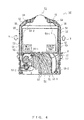
ink ribbon cassette 50 is stored with itsmaterial 52 accordion folded in aribbon storage unit 51, a box-shaped part located at the bottom, as shown in the cross-sectional view inFig. 4 . The upper side of the box-shaped part at the bottom is a C- shaped part having an opening upward, and a first ribbon path 54-1 and a second ribbon path 54-2 project from the box. - When the
ink ribbon cassette 50 is set to the above passbook printer unit (not shown), anink ribbon 52 that is crossing over the opening of the C-shaped part is sandwiched by the print head (not shown) of the passbook printer unit and the medium (writing surface of the passbook). - The
ribbon 52 stored in theribbon storage unit 51 in an accordion folded state is an endless ink ribbon (hereinafter, simply referred to as a "ribbon"), which is in the form of a loop. - This
ribbon 52 is wound in the direction of arrow Y by a feed gear 56-2 rotating in direction of arrow X, is clipped by aplate spring 57 on the outlet port side of theribbon storage unit 51, is fed onto the first ribbon path 54-1, moves upward and then diagonally upward right on the first ribbon path 54-1, and reaches the position of the print head. The feed gear 56-2 is one of two feed gears 56-1 and 56-2 provided on the inlet port side of theribbon storage unit 51. - Thereafter, the
ribbon 52 is wound in the direction of arrow Y by the feed gear 56-2 rotating in the direction of arrow X, moves diagonally downward left and then downward from the position of the print head on the second ribbon path 54-2, passes through the position at which the feed gears 56-1 and 56-2 are set, and is stored again in the accordion folded state in theribbon storage unit 51. - On the outlet port of the
ribbon storage unit 51, a first bank 58-1 and a second bank 58-2 are provided that are projections in which both of their ends in the width direction orthogonal to the winding direction of the material (ribbon) 52 contact the walls. - Note that this cross-sectional view does not show respective corresponding banks provided on the cover of the opposing side.
- Both edges in the width direction of the banks 58-1 and 58-2 push the ribbon stored in an accordioned state in the
ribbon storage unit 51 so that theribbon 52 is kept in the space further inward (left side inFig. 4 ) than the first bank 58-1 of theribbon storage unit 51, or, when possible, so that theribbon 52 is kept in the space (left side inFig. 4 ) further inward than the second bank 58-2 of theribbon storage unit 51. - Thereby an aim is to prevent a situation where the
ribbon 52 that has been stored in the accordioned state in theribbon storage unit 51 accumulates in the vicinity of position P at which theribbon 52 is clipped by theplate spring 57 on the first ribbon path 54-1 on the outlet port side of theribbon storage unit 51 and the material (ribbon) 52 is fed out doubly. The double feed will be explained later. - On the cover of the opposite side of the cross-sectional view of
Fig. 4 , felt (not shown) for supplying ink to the position below the feed gear 56-2 is provided. - Repeated use of the
ribbon 52 increases the number of times that the print head prints on a medium. Accompanying this, the rigidity of the material (ribbon) 52 itself decreases, or thematerial 52 itself shrinks so as to get on the first and second banks 58-1 and 58-2, as shown inFig. 5 , so that theribbon 52 accumulates in an accordioned manner in the vicinity of position P from which theribbon 52 is to be fed out and is clipped by theplate spring 57. - When the wind up (running) operations of the
ribbon 52 are continued in the above situation, the double feed of the material (ribbon) occurs. Specifically, a plurality of materials (ribbons) 52 stored in theribbon storage unit 51 are conveyed simultaneously. - As a result of this, the running load of the material increases, and the material stops during the conveyance so that multiple printing on the same position, faint printing, omission, or the like occurs when the printing unit performs printing using the
ink ribbon 52. - There is a demand for a mechanism that prevents double feeding when continuous use of the material (ribbon) 52 has caused a decrease in the rigidity or shrinkage of the material, causing a poor storage condition where the material (ribbon) 52 concentrates around the output port in the
ribbon storage unit 51. - In
Patent Document 1, as a related art, a plurality of ribs are provided alternately at constant intervals on both walls of the first and second ribbon paths in order to separate the material (eliminate the overlapping) . The first path is used for feeding the ink ribbon to the print head, and the second path is used for returning the ribbon from the print head so that material does not overlap. - However, when the above related art is actually implemented, even though the plurality of ribs alternately provided to both walls of ribbon paths are effective in eliminating the overlapping of the ink ribbon, it has been proven that a single rib does not cause sufficient effects in eliminating the overlapping. In practice, a plurality of
ribs 59 are provided alternately to both walls of the ribbon paths inFigs. 4 and5 . In the present application too, thestructure using ribs 59 on both walls of the ribbon paths is employed, although this configuration is not shown. - Also, in
Patent Document 2, a pair of rotatable pins are provided to a position outside of the inlet port of the ribbon storage unit in a stage later than the print head in order to make the ink ribbon travel between the paired pins so that the ink ribbon does not overlap. However, this is performed in a stage later than the print head, and the paired pins are close to the roller for winding up the ribbon. This cannot prevent deterioration in printing quality, although it may increase the possibility of eliminating the overlapping of the ink ribbon. - Patent Document 1: Japanese Laid-open Utility Publication NO.
H5-39968 - Patent Document 2: Japanese Laid-open Patent Publication No.
H9-76610 - The present invention has been achieved in order to solve the above problem, and aims to provide an ink ribbon cassette that smoothly winds up an ink ribbon while preventing deterioration in the quality of printing performed by an ink head using the ink ribbon.
- A first proposed ink ribbon cassette is an ink ribbon cassette having a ribbon storage unit for storing an endless ink ribbon.
- This first ink ribbon cassette includes material separation means for eliminating overlapping in a longitudinal direction of an ink ribbon when the ink ribbon that has been fed back from a printing unit and has been stored in an accordioned state in the ribbon storage unit is fed to a printing unit again, and a plate spring for pushing, at an outlet port side of the ribbon storage unit, the ink ribbon onto one of the walls of a path for feeding the ink ribbon to the printing unit, in which the material separation means includes two pins provided with an interval between themselves to form a narrow slit for eliminating the overlapping and making the ink ribbon pass through the slit as a single sheet of ribbon.
- A second proposed ink ribbon cassette is the first ink ribbon cassette in which the material separation means further includes ribs each having one end provided successively to one of the two pins and having the other end provided to contact a wall of the ribbon storage unit so as to control a movement position of the ink ribbon.
- A third proposed ink ribbon cassette is the second ink ribbon cassette in which a height of the controlling ribs is smaller than half of a width of material of the ink ribbon.
- According to the first proposed ink ribbon cassette, the ribbon storage unit has two pins to form a narrow slit to eliminate overlapping in longitudinal direction of the ink ribbon so as to make the ribbon pass through the slit as a single ribbon, and thereby, the overlapping of the ribbon (material) in the longitudinal direction orthogonal to the width direction is eliminated. This can prevent a situation where overlapping of the material causes multiple printing on the same position, faint printing, omission, or the like during printing, increasing the printing quality.
- In a second proposed ink ribbon cassette, a rib having one end that continues to one of the above two pins and another end that contacts a wall of the ribbon storage unit is provided to control the movement position of the ink ribbon, so as to make it more difficult for the ink ribbon stored accordionedly in the ribbon storage unit to approach the path for feeding the ribbon to the printing unit unless it approaches by passing between the pins. This can separate (eliminate) overlapping of the ink ribbon more surely.
- In a third proposed ink ribbon cassette, the height of the rib is set to be smaller than half of the width of the ink ribbon material used in the second ink ribbon cassette so that loads of the running ribbon are reduced, and it is also possible to prevent ribs from being contaminated by multiple transcriptions of a plurality of colors of ink (red and black) when a red/black ribbon is used.
-
-
Fig. 1 is a cross-sectional view showing the main part of an ink ribbon cassette according to an embodiment of the present invention; -
Fig. 2 shows a black ribbon and a red-black ribbon; -
Fig. 3 is a cross-sectional view showing the main part of an ink ribbon cassette according to a variation example of the present embodiment; -
Fig. 4 is a cross-sectional view showing a conventional ink ribbon cassette; and -
Fig. 5 shows a problem caused in a conventional ink ribbon cassette. - Hereinafter, embodiments of the present invention will be explained in detail by referring to the drawings.
-
Fig. 1 is a cross-sectional view showing the main part of an ink ribbon cassette according to an embodiment of the present invention. Thisink ribbon cassette 1 is used for a PPR (Passbook Printer Unit) of an ATM or the like. - As shown in
Fig. 1 , theink ribbon cassette 1 of the present invention hasribbon material 3 stored in an accordion folded state in aribbon storage unit 2, which is a box-shaped part located at the bottom. On the upper side of the box- shaped part at the bottom is a C-shaped part having an opening facing upward, and a first ribbon patch 4-1 and a second ribbon patch 4-2 project from the box, although the upper part is not shown entirely. - When the
ink ribbon cassette 1 is set in the above passbook printer unit (not shown), theink ribbon 3 crosses over the C-shaped opening, and is sandwiched between the print head (not shown) of the passbook printer unit and the medium (writing surface of the passbook). - The
ribbon 3 that is stored in an accordion folded state in theribbon storage unit 2 is an endless ink ribbon (hereinafter, simply referred to as a "ribbon"), which is in a form of loop. - This
ribbon 3 is wound in the direction of arrow Y by a feed gear 6-2 rotating in direction of arrow X, is clipped by aplate spring 7 on the outlet port side of theribbon storage unit 2, is fed onto a first ribbon path 4-1, moves upward on the first ribbon path 4 - 1, and reaches the position of the print head. The feed gear 6-2 is one of two feed gears 6-1 and 6-2 provided on the inlet port side of theribbon storage unit 2. - Thereafter, the
ribbon 3 is wound in the direction of arrow Y by the feed gear 6-2 rotating in direction of arrow X, moves downward on the second ribbon path 4-2 from the position of the print head, passes through the position at which the feed gears are set, and is stored again in an accordioned state in theribbon storage unit 2. - On the outlet port side of the
ribbon storage unit 2, a first bask 8-1 and a second bank 8-2 are provided that are projections in which both ends in the width direction orthogonal to the winding direction of the material (ribbon) 3 abut the walls. - Note that this cross-sectional view does not show respective corresponding banks provided on the cover of the opposing side.
- In this example, a case is assumed where continuous use of the material (ribbon) 3 has caused a decrease in rigidity of the material or shrinkage, causing an improper storage condition where the material (ribbon) 3 concentrates around the output port in the
ribbon storage unit 2. - In such a case, when a conventional internal configuration is adopted for the
ribbon storage unit 2, it is expected that the material (ribbon) 3 stored in theribbon storage unit 2 will run onto the first and second banks 8 - 1 and 8-2 so that theribbon 3 in an accordion folded state accumulates in the vicinity of position P from which theribbon 3 is to be fed out and is clipped by theplate spring 7, or so that part of theribbon 3 in an accordion folded state reaches position P. - However, in the present embodiment, ribs 11-1 and 11-2 are provided in the vicinity of the outlet port of the
ribbon storage unit 2 in such a manner that these ribs 11-1 and 11-2 lean on the second bank 8-2, which is located further outward than the first bank 8 - 1. Thereby, theribbon 3 in an accordioned state is prevented from approaching the vicinity of position P from which theribbon 3 is fed out is clipped by theplate spring 7. - Paired rotatable pins 12-1 and 12-2 are provided to the ribs 11-1 and 11-2 at the side opposite to the side contacting the wall of the
ribbon storage unit 2 in order to eliminate the overlapping (double feeding) of theribbon 3 traveling toward the vicinity of position P from which theribbon 3 is fed out and is clipped by theplate spring 7 by making the ribbon pass between the paired pins 12-1 and 12-2. - In other words, when the material (ribbon) 3 passes between the pins 12-1 and 12-2, the overlapping of the material be eliminated.
- Even when the material passes the pins 12-1 and 12-2 in an overlapped state, the overlapping of the material can be eliminated in space P surrounded by the ribs 11-1, 11-2, pins 12-1, 12-2, and the
plate spring 7. - Further, even after the
ribbon 3 has been fed out onto the first ribbon path 4-1 from theplate spring 7, the overlapping of thematerial 3 can be eliminated by a plurality of ribs (not shown) provided alternately on both walls of the first ribbon path 4-1. - Note that the height of the ribs 11-1 and 11-2 are smaller than half of the width of the
material 3, as shown in the side sectional view in direction A-A in cross-sectional view ofFig. 1 . - As shown in
Fig. 2 , types of endless ink ribbons include ablack ribbon 14, to which black ink has been applied, and a red-black ribbon 16, on which a red side 16-1 and a black side 16-2 are arranged in a striped manner. Red ink has been applied to the red side 16-1 and black has been applied to the black side 16-2. - When the red-
black ribbon 16 is used, a black side 16-2 is used for printing more frequently, and the rigidity of the material of the black side 16-2 decreases earlier than the red side 16-1, causing folding to develop in the black side 16-2 in the direction of the width of thematerial 3. This makes the red side 16-1 of the maternal 3 contact the ribs 11-1 and 11-2, and red ink is transferred to the ribs 11-1 and 11-2 so that a plurality of colors (black and red in this case) of ink are multiply transferred, contaminating the ribs 11-1 and 11-2. - Also, red ink which is primarily meant to be transferred onto the printing surface of the medium, is transferred to the ribs 11-1 and 11-2, reducing the amount of the red ink that is actually applied to the printing surface.
- By making the height of the ribs 11-1 and 11-2 shorter than half of the width of the
material 3, ribs 11-1 and 11-2 can be prevented from being stained. - Also, the running load of the
ribbon 3 increases in proportion to the area contacting the ribs 11-1 and 11-2, and accordingly the reduction of the contacting area decreases the running load of theribbon 3. - As has been described above, according to the present embodiment, the ribs 11-1 and 11-2 and the pins 12-1 and 12-2 are provided in a stage earlier than the outlet port of the
ribbon storage unit 2 so that the overlapping in the direction orthogonal to the width direction of the ribbon (material) 3 is separated (eliminated). This makes it possible to avoid multiple printing onto the same places, faint printing, omission, and the like, thereby increasing the printing quality. - Also, the pins 12-1 and 12-2 are rotatable, and the height of the ribs 11-1 and 11-2 are designed to be smaller than half of the width of the
material 3, taking into consideration the use of, for example, the red-black ribbon, and accordingly the running load of theribbon 3 can be reduced. - Also, because the height of the ribs 11-1 and 11-2 is made to be smaller than half of the width of the material, stains on ribs 11-1 and 11-2 can be prevented that would otherwise be caused by multiple transfers of a plurality of colors (red and black) of ink when a red-black ribbon is used.
- Repeated use of the
ribbon 3 stored in an accordioned state in theribbon storage unit 2 has reduced the rigidity of the material itself and has caused shrinkage so that theribbon 3 accumulates on the output port side of theribbon storage unit 2 after running onto the first and second banks 8-1 and 8-2 in an accordion folded state. Because of this, it is possible to prevent theribbon 3 from approaching the vicinity of the outlet port at a single position when it is taken into consideration that the entire ribbon moves to the outlet side. - This means that, as shown in the cross-sectional view shown in
Fig. 3 and a side-sectional view viewed in direction B-B of the cross-sectional view inFig. 3 , it is also possible to employ only two pins 12-1 and 12-2, omitting the ribs 11-1 and 11-2. Also, even when the pins 12-1 and 12-2 do not rotate, the same effect can be achieved. - It is also possible to employ a variation form in which only one of the ribs 11-1 and 11-2 is provided, or like.
Claims (4)
- An ink ribbon cassette (1) including a ribbon storage unit (2) for storing an endless ink ribbon (3), comprising:material separation means for eliminating overlapping yin a longitudinal direction of the ink ribbon (3) when the ink ribbon (3) that has been fed back from a printing unit and has been stored in an accordioned state in the ribbon storage unit (2) is fed to a printing unit again; anda plate spring (7) for pushing, at an outlet port side of the ribbon storage unit (2), the ink ribbon (3) onto one side wall of a path for feeding the ink ribbon (3) to the printing unit, wherein:the material separation means includes two pins (12-1 and 12-2) provided with an interval between themselves to form a narrow slit for eliminating the overlapping and making the ink ribbon (3) pass through the slit as a single sheet of ribbon.
- The ink ribbon cassette (1) according to claim 1, wherein:the material separation means further includes ribs (11-1 and 11-2) each having one end provided successively to one of the two pins (12-1 and 12-2) and having the other end provided to contact a wall of the ribbon storage unit (2) so as to control a movement position of the ink ribbon (3).
- The ink ribbon cassette (1) according to claim 2, wherein:a height of the controlling ribs (11-1 and 11-2) is smaller than half of a width of material of the ink ribbon (3).
- The ink ribbon cassette (1) according to one of claims 1 through 3, wherein:a plurality of ribs are arranged alternately with intervals on a path for feeding the ink ribbon (3) to the printing unit and on both sides of a side wall (4-1) of a path for feeding back the ink ribbon (3) from the printing unit in order to eliminate overlapping of the ink ribbon (3).
Applications Claiming Priority (1)
| Application Number | Priority Date | Filing Date | Title |
|---|---|---|---|
| JP2011287029A JP5744715B2 (en) | 2011-12-27 | 2011-12-27 | Ink ribbon cassette |
Publications (2)
| Publication Number | Publication Date |
|---|---|
| EP2610066A1 true EP2610066A1 (en) | 2013-07-03 |
| EP2610066B1 EP2610066B1 (en) | 2014-05-14 |
Family
ID=47603029
Family Applications (1)
| Application Number | Title | Priority Date | Filing Date |
|---|---|---|---|
| EP12198046.0A Not-in-force EP2610066B1 (en) | 2011-12-27 | 2012-12-19 | Ink ribbon cassette |
Country Status (5)
| Country | Link |
|---|---|
| EP (1) | EP2610066B1 (en) |
| JP (1) | JP5744715B2 (en) |
| KR (1) | KR101417494B1 (en) |
| CN (1) | CN103182867B (en) |
| ES (1) | ES2466219T3 (en) |
Citations (6)
| Publication number | Priority date | Publication date | Assignee | Title |
|---|---|---|---|---|
| DE3015726A1 (en) * | 1980-04-24 | 1981-10-29 | Olympia Werke Ag, 2940 Wilhelmshaven | CONTINUOUS RIBBON TAPE FOR A WRITING O.AE. OFFICE MACHINE |
| US4405247A (en) * | 1978-06-05 | 1983-09-20 | Centronics Data Computer Corp. | Fully self-contained disposable cartridge for inked ribbons and the like |
| GB2184998A (en) * | 1986-01-08 | 1987-07-08 | Canon Kk | Ink ribbon cassette |
| EP0240112A1 (en) * | 1986-02-28 | 1987-10-07 | Ing. C. Olivetti & C., S.p.A. | Cartridge for an inked ribbon with a re-inking device |
| JPH0539968U (en) | 1991-10-25 | 1993-05-28 | フジコピアン株式会社 | Ink ribbon cassette |
| JPH0976610A (en) | 1995-09-18 | 1997-03-25 | Fujicopian Co Ltd | Ink ribbon cassette |
Family Cites Families (9)
| Publication number | Priority date | Publication date | Assignee | Title |
|---|---|---|---|---|
| JPS56111686A (en) * | 1980-02-06 | 1981-09-03 | Tokyo Electric Co Ltd | Ink ribbon cartridge of printer |
| JPS6368460U (en) * | 1986-10-23 | 1988-05-09 | ||
| JPH0212860U (en) * | 1988-07-08 | 1990-01-26 | ||
| JPH0736767Y2 (en) * | 1989-02-28 | 1995-08-23 | 富士化学紙工業株式会社 | Ink ribbon cartridge |
| JP2607372Y2 (en) * | 1993-04-13 | 2001-07-09 | ブラザー工業株式会社 | Color ink ribbon cassette |
| JPH07246171A (en) * | 1994-03-10 | 1995-09-26 | Akiko Tajima | Skin cleaning aid |
| JPH07246761A (en) * | 1994-03-11 | 1995-09-26 | Pilot Corp:The | Ribbon cassette |
| JPH0872367A (en) * | 1994-09-08 | 1996-03-19 | Fujitsu Isotec Ltd | Film ribbon splicing method and ribbon cassette |
| JP2000141843A (en) * | 1998-11-10 | 2000-05-23 | Fujicopian Co Ltd | Multicolor ink ribbon cassette |
-
2011
- 2011-12-27 JP JP2011287029A patent/JP5744715B2/en not_active Expired - Fee Related
-
2012
- 2012-12-18 KR KR1020120148734A patent/KR101417494B1/en not_active Expired - Fee Related
- 2012-12-19 CN CN201210554796.6A patent/CN103182867B/en not_active Expired - Fee Related
- 2012-12-19 EP EP12198046.0A patent/EP2610066B1/en not_active Not-in-force
- 2012-12-19 ES ES12198046.0T patent/ES2466219T3/en active Active
Patent Citations (6)
| Publication number | Priority date | Publication date | Assignee | Title |
|---|---|---|---|---|
| US4405247A (en) * | 1978-06-05 | 1983-09-20 | Centronics Data Computer Corp. | Fully self-contained disposable cartridge for inked ribbons and the like |
| DE3015726A1 (en) * | 1980-04-24 | 1981-10-29 | Olympia Werke Ag, 2940 Wilhelmshaven | CONTINUOUS RIBBON TAPE FOR A WRITING O.AE. OFFICE MACHINE |
| GB2184998A (en) * | 1986-01-08 | 1987-07-08 | Canon Kk | Ink ribbon cassette |
| EP0240112A1 (en) * | 1986-02-28 | 1987-10-07 | Ing. C. Olivetti & C., S.p.A. | Cartridge for an inked ribbon with a re-inking device |
| JPH0539968U (en) | 1991-10-25 | 1993-05-28 | フジコピアン株式会社 | Ink ribbon cassette |
| JPH0976610A (en) | 1995-09-18 | 1997-03-25 | Fujicopian Co Ltd | Ink ribbon cassette |
Also Published As
| Publication number | Publication date |
|---|---|
| ES2466219T3 (en) | 2014-06-09 |
| JP5744715B2 (en) | 2015-07-08 |
| CN103182867B (en) | 2016-06-29 |
| EP2610066B1 (en) | 2014-05-14 |
| CN103182867A (en) | 2013-07-03 |
| JP2013136152A (en) | 2013-07-11 |
| KR20130075664A (en) | 2013-07-05 |
| KR101417494B1 (en) | 2014-07-08 |
Similar Documents
| Publication | Publication Date | Title |
|---|---|---|
| DE69809353T2 (en) | Sheet feeder with a compact transport path | |
| EP2520436B1 (en) | Printing device | |
| CN103660614A (en) | Printer | |
| EP2082885A1 (en) | Continuous paper web duplex inkjet printing unit | |
| US20110243635A1 (en) | Printing system, sheet processing system, and sheet direction changingapparatus | |
| DE3602011C2 (en) | ||
| JP2011241036A (en) | Paper sheet cassette and image forming device | |
| JPS6120792A (en) | Ribbon cassette | |
| EP2610066B1 (en) | Ink ribbon cassette | |
| US8029202B2 (en) | Printer with recording paper leading edge storage unit | |
| US7644918B2 (en) | Sheet discharge system | |
| JP2002154725A (en) | Inkjet printer | |
| JP4873955B2 (en) | Print media sheet feeding system | |
| CN102189853A (en) | with box | |
| EP0224347B1 (en) | Ribbon cassette for printers | |
| US8770873B2 (en) | Ink ribbon cassette and printing apparatus | |
| US9415955B2 (en) | Recording apparatus | |
| JP5495928B2 (en) | Sheet supply unit and printer | |
| US20250042186A1 (en) | Printer | |
| JPH0534944Y2 (en) | ||
| JP5528192B2 (en) | Sheet stacking device and printer | |
| JP2008001069A (en) | Printer | |
| JP2008230073A (en) | Printer | |
| DE2638605C2 (en) | ||
| JPH0539968U (en) | Ink ribbon cassette |
Legal Events
| Date | Code | Title | Description |
|---|---|---|---|
| PUAI | Public reference made under article 153(3) epc to a published international application that has entered the european phase |
Free format text: ORIGINAL CODE: 0009012 |
|
| AK | Designated contracting states |
Kind code of ref document: A1 Designated state(s): AL AT BE BG CH CY CZ DE DK EE ES FI FR GB GR HR HU IE IS IT LI LT LU LV MC MK MT NL NO PL PT RO RS SE SI SK SM TR |
|
| AX | Request for extension of the european patent |
Extension state: BA ME |
|
| 17P | Request for examination filed |
Effective date: 20130926 |
|
| RBV | Designated contracting states (corrected) |
Designated state(s): AL AT BE BG CH CY CZ DE DK EE ES FI FR GB GR HR HU IE IS IT LI LT LU LV MC MK MT NL NO PL PT RO RS SE SI SK SM TR |
|
| GRAP | Despatch of communication of intention to grant a patent |
Free format text: ORIGINAL CODE: EPIDOSNIGR1 |
|
| INTG | Intention to grant announced |
Effective date: 20131202 |
|
| GRAS | Grant fee paid |
Free format text: ORIGINAL CODE: EPIDOSNIGR3 |
|
| GRAA | (expected) grant |
Free format text: ORIGINAL CODE: 0009210 |
|
| AK | Designated contracting states |
Kind code of ref document: B1 Designated state(s): AL AT BE BG CH CY CZ DE DK EE ES FI FR GB GR HR HU IE IS IT LI LT LU LV MC MK MT NL NO PL PT RO RS SE SI SK SM TR |
|
| REG | Reference to a national code |
Ref country code: GB Ref legal event code: FG4D |
|
| REG | Reference to a national code |
Ref country code: ES Ref legal event code: FG2A Ref document number: 2466219 Country of ref document: ES Kind code of ref document: T3 Effective date: 20140609 |
|
| REG | Reference to a national code |
Ref country code: AT Ref legal event code: REF Ref document number: 667950 Country of ref document: AT Kind code of ref document: T Effective date: 20140615 |
|
| REG | Reference to a national code |
Ref country code: IE Ref legal event code: FG4D Ref country code: DE Ref legal event code: R096 Ref document number: 602012001800 Country of ref document: DE Effective date: 20140618 |
|
| REG | Reference to a national code |
Ref country code: AT Ref legal event code: MK05 Ref document number: 667950 Country of ref document: AT Kind code of ref document: T Effective date: 20140514 Ref country code: NL Ref legal event code: VDEP Effective date: 20140514 |
|
| REG | Reference to a national code |
Ref country code: LT Ref legal event code: MG4D |
|
| PG25 | Lapsed in a contracting state [announced via postgrant information from national office to epo] |
Ref country code: NO Free format text: LAPSE BECAUSE OF FAILURE TO SUBMIT A TRANSLATION OF THE DESCRIPTION OR TO PAY THE FEE WITHIN THE PRESCRIBED TIME-LIMIT Effective date: 20140814 Ref country code: FI Free format text: LAPSE BECAUSE OF FAILURE TO SUBMIT A TRANSLATION OF THE DESCRIPTION OR TO PAY THE FEE WITHIN THE PRESCRIBED TIME-LIMIT Effective date: 20140514 Ref country code: CY Free format text: LAPSE BECAUSE OF FAILURE TO SUBMIT A TRANSLATION OF THE DESCRIPTION OR TO PAY THE FEE WITHIN THE PRESCRIBED TIME-LIMIT Effective date: 20140514 Ref country code: GR Free format text: LAPSE BECAUSE OF FAILURE TO SUBMIT A TRANSLATION OF THE DESCRIPTION OR TO PAY THE FEE WITHIN THE PRESCRIBED TIME-LIMIT Effective date: 20140815 Ref country code: IS Free format text: LAPSE BECAUSE OF FAILURE TO SUBMIT A TRANSLATION OF THE DESCRIPTION OR TO PAY THE FEE WITHIN THE PRESCRIBED TIME-LIMIT Effective date: 20140914 Ref country code: LT Free format text: LAPSE BECAUSE OF FAILURE TO SUBMIT A TRANSLATION OF THE DESCRIPTION OR TO PAY THE FEE WITHIN THE PRESCRIBED TIME-LIMIT Effective date: 20140514 |
|
| PG25 | Lapsed in a contracting state [announced via postgrant information from national office to epo] |
Ref country code: HR Free format text: LAPSE BECAUSE OF FAILURE TO SUBMIT A TRANSLATION OF THE DESCRIPTION OR TO PAY THE FEE WITHIN THE PRESCRIBED TIME-LIMIT Effective date: 20140514 Ref country code: PL Free format text: LAPSE BECAUSE OF FAILURE TO SUBMIT A TRANSLATION OF THE DESCRIPTION OR TO PAY THE FEE WITHIN THE PRESCRIBED TIME-LIMIT Effective date: 20140514 Ref country code: RS Free format text: LAPSE BECAUSE OF FAILURE TO SUBMIT A TRANSLATION OF THE DESCRIPTION OR TO PAY THE FEE WITHIN THE PRESCRIBED TIME-LIMIT Effective date: 20140514 Ref country code: AT Free format text: LAPSE BECAUSE OF FAILURE TO SUBMIT A TRANSLATION OF THE DESCRIPTION OR TO PAY THE FEE WITHIN THE PRESCRIBED TIME-LIMIT Effective date: 20140514 Ref country code: LV Free format text: LAPSE BECAUSE OF FAILURE TO SUBMIT A TRANSLATION OF THE DESCRIPTION OR TO PAY THE FEE WITHIN THE PRESCRIBED TIME-LIMIT Effective date: 20140514 Ref country code: SE Free format text: LAPSE BECAUSE OF FAILURE TO SUBMIT A TRANSLATION OF THE DESCRIPTION OR TO PAY THE FEE WITHIN THE PRESCRIBED TIME-LIMIT Effective date: 20140514 |
|
| PG25 | Lapsed in a contracting state [announced via postgrant information from national office to epo] |
Ref country code: PT Free format text: LAPSE BECAUSE OF FAILURE TO SUBMIT A TRANSLATION OF THE DESCRIPTION OR TO PAY THE FEE WITHIN THE PRESCRIBED TIME-LIMIT Effective date: 20140915 |
|
| PG25 | Lapsed in a contracting state [announced via postgrant information from national office to epo] |
Ref country code: CZ Free format text: LAPSE BECAUSE OF FAILURE TO SUBMIT A TRANSLATION OF THE DESCRIPTION OR TO PAY THE FEE WITHIN THE PRESCRIBED TIME-LIMIT Effective date: 20140514 Ref country code: SK Free format text: LAPSE BECAUSE OF FAILURE TO SUBMIT A TRANSLATION OF THE DESCRIPTION OR TO PAY THE FEE WITHIN THE PRESCRIBED TIME-LIMIT Effective date: 20140514 Ref country code: DK Free format text: LAPSE BECAUSE OF FAILURE TO SUBMIT A TRANSLATION OF THE DESCRIPTION OR TO PAY THE FEE WITHIN THE PRESCRIBED TIME-LIMIT Effective date: 20140514 Ref country code: RO Free format text: LAPSE BECAUSE OF FAILURE TO SUBMIT A TRANSLATION OF THE DESCRIPTION OR TO PAY THE FEE WITHIN THE PRESCRIBED TIME-LIMIT Effective date: 20140514 Ref country code: EE Free format text: LAPSE BECAUSE OF FAILURE TO SUBMIT A TRANSLATION OF THE DESCRIPTION OR TO PAY THE FEE WITHIN THE PRESCRIBED TIME-LIMIT Effective date: 20140514 Ref country code: BE Free format text: LAPSE BECAUSE OF FAILURE TO SUBMIT A TRANSLATION OF THE DESCRIPTION OR TO PAY THE FEE WITHIN THE PRESCRIBED TIME-LIMIT Effective date: 20140514 |
|
| REG | Reference to a national code |
Ref country code: DE Ref legal event code: R097 Ref document number: 602012001800 Country of ref document: DE |
|
| PG25 | Lapsed in a contracting state [announced via postgrant information from national office to epo] |
Ref country code: NL Free format text: LAPSE BECAUSE OF FAILURE TO SUBMIT A TRANSLATION OF THE DESCRIPTION OR TO PAY THE FEE WITHIN THE PRESCRIBED TIME-LIMIT Effective date: 20140514 |
|
| PLBE | No opposition filed within time limit |
Free format text: ORIGINAL CODE: 0009261 |
|
| STAA | Information on the status of an ep patent application or granted ep patent |
Free format text: STATUS: NO OPPOSITION FILED WITHIN TIME LIMIT |
|
| 26N | No opposition filed |
Effective date: 20150217 |
|
| PG25 | Lapsed in a contracting state [announced via postgrant information from national office to epo] |
Ref country code: IT Free format text: LAPSE BECAUSE OF FAILURE TO SUBMIT A TRANSLATION OF THE DESCRIPTION OR TO PAY THE FEE WITHIN THE PRESCRIBED TIME-LIMIT Effective date: 20140514 |
|
| REG | Reference to a national code |
Ref country code: DE Ref legal event code: R097 Ref document number: 602012001800 Country of ref document: DE Effective date: 20150217 |
|
| REG | Reference to a national code |
Ref country code: DE Ref legal event code: R119 Ref document number: 602012001800 Country of ref document: DE |
|
| PG25 | Lapsed in a contracting state [announced via postgrant information from national office to epo] |
Ref country code: LU Free format text: LAPSE BECAUSE OF FAILURE TO SUBMIT A TRANSLATION OF THE DESCRIPTION OR TO PAY THE FEE WITHIN THE PRESCRIBED TIME-LIMIT Effective date: 20141219 Ref country code: SI Free format text: LAPSE BECAUSE OF FAILURE TO SUBMIT A TRANSLATION OF THE DESCRIPTION OR TO PAY THE FEE WITHIN THE PRESCRIBED TIME-LIMIT Effective date: 20140514 |
|
| REG | Reference to a national code |
Ref country code: IE Ref legal event code: MM4A |
|
| REG | Reference to a national code |
Ref country code: FR Ref legal event code: ST Effective date: 20150831 |
|
| PG25 | Lapsed in a contracting state [announced via postgrant information from national office to epo] |
Ref country code: DE Free format text: LAPSE BECAUSE OF NON-PAYMENT OF DUE FEES Effective date: 20150701 Ref country code: IE Free format text: LAPSE BECAUSE OF NON-PAYMENT OF DUE FEES Effective date: 20141219 |
|
| PG25 | Lapsed in a contracting state [announced via postgrant information from national office to epo] |
Ref country code: FR Free format text: LAPSE BECAUSE OF NON-PAYMENT OF DUE FEES Effective date: 20141231 |
|
| PG25 | Lapsed in a contracting state [announced via postgrant information from national office to epo] |
Ref country code: MC Free format text: LAPSE BECAUSE OF FAILURE TO SUBMIT A TRANSLATION OF THE DESCRIPTION OR TO PAY THE FEE WITHIN THE PRESCRIBED TIME-LIMIT Effective date: 20140514 |
|
| PG25 | Lapsed in a contracting state [announced via postgrant information from national office to epo] |
Ref country code: BG Free format text: LAPSE BECAUSE OF FAILURE TO SUBMIT A TRANSLATION OF THE DESCRIPTION OR TO PAY THE FEE WITHIN THE PRESCRIBED TIME-LIMIT Effective date: 20140514 |
|
| PG25 | Lapsed in a contracting state [announced via postgrant information from national office to epo] |
Ref country code: TR Free format text: LAPSE BECAUSE OF FAILURE TO SUBMIT A TRANSLATION OF THE DESCRIPTION OR TO PAY THE FEE WITHIN THE PRESCRIBED TIME-LIMIT Effective date: 20140514 Ref country code: HU Free format text: LAPSE BECAUSE OF FAILURE TO SUBMIT A TRANSLATION OF THE DESCRIPTION OR TO PAY THE FEE WITHIN THE PRESCRIBED TIME-LIMIT; INVALID AB INITIO Effective date: 20121219 Ref country code: MT Free format text: LAPSE BECAUSE OF FAILURE TO SUBMIT A TRANSLATION OF THE DESCRIPTION OR TO PAY THE FEE WITHIN THE PRESCRIBED TIME-LIMIT Effective date: 20140514 |
|
| REG | Reference to a national code |
Ref country code: CH Ref legal event code: PL |
|
| PG25 | Lapsed in a contracting state [announced via postgrant information from national office to epo] |
Ref country code: LI Free format text: LAPSE BECAUSE OF NON-PAYMENT OF DUE FEES Effective date: 20151231 Ref country code: CH Free format text: LAPSE BECAUSE OF NON-PAYMENT OF DUE FEES Effective date: 20151231 |
|
| PG25 | Lapsed in a contracting state [announced via postgrant information from national office to epo] |
Ref country code: SM Free format text: LAPSE BECAUSE OF FAILURE TO SUBMIT A TRANSLATION OF THE DESCRIPTION OR TO PAY THE FEE WITHIN THE PRESCRIBED TIME-LIMIT Effective date: 20140514 |
|
| GBPC | Gb: european patent ceased through non-payment of renewal fee |
Effective date: 20161219 |
|
| PG25 | Lapsed in a contracting state [announced via postgrant information from national office to epo] |
Ref country code: GB Free format text: LAPSE BECAUSE OF NON-PAYMENT OF DUE FEES Effective date: 20161219 |
|
| PG25 | Lapsed in a contracting state [announced via postgrant information from national office to epo] |
Ref country code: MK Free format text: LAPSE BECAUSE OF FAILURE TO SUBMIT A TRANSLATION OF THE DESCRIPTION OR TO PAY THE FEE WITHIN THE PRESCRIBED TIME-LIMIT Effective date: 20140514 |
|
| PG25 | Lapsed in a contracting state [announced via postgrant information from national office to epo] |
Ref country code: AL Free format text: LAPSE BECAUSE OF FAILURE TO SUBMIT A TRANSLATION OF THE DESCRIPTION OR TO PAY THE FEE WITHIN THE PRESCRIBED TIME-LIMIT Effective date: 20140514 |
|
| PGFP | Annual fee paid to national office [announced via postgrant information from national office to epo] |
Ref country code: ES Payment date: 20200102 Year of fee payment: 8 |
|
| REG | Reference to a national code |
Ref country code: ES Ref legal event code: FD2A Effective date: 20220412 |
|
| PG25 | Lapsed in a contracting state [announced via postgrant information from national office to epo] |
Ref country code: ES Free format text: LAPSE BECAUSE OF NON-PAYMENT OF DUE FEES Effective date: 20201220 |