EP2609986A1 - Gas-liquid contactor and co2 recovery device - Google Patents
Gas-liquid contactor and co2 recovery device Download PDFInfo
- Publication number
- EP2609986A1 EP2609986A1 EP11812139.1A EP11812139A EP2609986A1 EP 2609986 A1 EP2609986 A1 EP 2609986A1 EP 11812139 A EP11812139 A EP 11812139A EP 2609986 A1 EP2609986 A1 EP 2609986A1
- Authority
- EP
- European Patent Office
- Prior art keywords
- liquid
- gas
- absorber
- wall
- nozzle
- Prior art date
- Legal status (The legal status is an assumption and is not a legal conclusion. Google has not performed a legal analysis and makes no representation as to the accuracy of the status listed.)
- Granted
Links
Images




Classifications
-
- B—PERFORMING OPERATIONS; TRANSPORTING
- B01—PHYSICAL OR CHEMICAL PROCESSES OR APPARATUS IN GENERAL
- B01D—SEPARATION
- B01D53/00—Separation of gases or vapours; Recovering vapours of volatile solvents from gases; Chemical or biological purification of waste gases, e.g. engine exhaust gases, smoke, fumes, flue gases, aerosols
- B01D53/14—Separation of gases or vapours; Recovering vapours of volatile solvents from gases; Chemical or biological purification of waste gases, e.g. engine exhaust gases, smoke, fumes, flue gases, aerosols by absorption
- B01D53/1456—Removing acid components
- B01D53/1475—Removing carbon dioxide
-
- C—CHEMISTRY; METALLURGY
- C01—INORGANIC CHEMISTRY
- C01B—NON-METALLIC ELEMENTS; COMPOUNDS THEREOF; METALLOIDS OR COMPOUNDS THEREOF NOT COVERED BY SUBCLASS C01C
- C01B32/00—Carbon; Compounds thereof
- C01B32/50—Carbon dioxide
-
- B—PERFORMING OPERATIONS; TRANSPORTING
- B01—PHYSICAL OR CHEMICAL PROCESSES OR APPARATUS IN GENERAL
- B01D—SEPARATION
- B01D2252/00—Absorbents, i.e. solvents and liquid materials for gas absorption
- B01D2252/20—Organic absorbents
- B01D2252/204—Amines
-
- B—PERFORMING OPERATIONS; TRANSPORTING
- B01—PHYSICAL OR CHEMICAL PROCESSES OR APPARATUS IN GENERAL
- B01D—SEPARATION
- B01D2257/00—Components to be removed
- B01D2257/50—Carbon oxides
- B01D2257/504—Carbon dioxide
-
- B—PERFORMING OPERATIONS; TRANSPORTING
- B01—PHYSICAL OR CHEMICAL PROCESSES OR APPARATUS IN GENERAL
- B01D—SEPARATION
- B01D2259/00—Type of treatment
- B01D2259/12—Methods and means for introducing reactants
- B01D2259/124—Liquid reactants
-
- Y—GENERAL TAGGING OF NEW TECHNOLOGICAL DEVELOPMENTS; GENERAL TAGGING OF CROSS-SECTIONAL TECHNOLOGIES SPANNING OVER SEVERAL SECTIONS OF THE IPC; TECHNICAL SUBJECTS COVERED BY FORMER USPC CROSS-REFERENCE ART COLLECTIONS [XRACs] AND DIGESTS
- Y02—TECHNOLOGIES OR APPLICATIONS FOR MITIGATION OR ADAPTATION AGAINST CLIMATE CHANGE
- Y02C—CAPTURE, STORAGE, SEQUESTRATION OR DISPOSAL OF GREENHOUSE GASES [GHG]
- Y02C20/00—Capture or disposal of greenhouse gases
- Y02C20/40—Capture or disposal of greenhouse gases of CO2
-
- Y—GENERAL TAGGING OF NEW TECHNOLOGICAL DEVELOPMENTS; GENERAL TAGGING OF CROSS-SECTIONAL TECHNOLOGIES SPANNING OVER SEVERAL SECTIONS OF THE IPC; TECHNICAL SUBJECTS COVERED BY FORMER USPC CROSS-REFERENCE ART COLLECTIONS [XRACs] AND DIGESTS
- Y02—TECHNOLOGIES OR APPLICATIONS FOR MITIGATION OR ADAPTATION AGAINST CLIMATE CHANGE
- Y02P—CLIMATE CHANGE MITIGATION TECHNOLOGIES IN THE PRODUCTION OR PROCESSING OF GOODS
- Y02P20/00—Technologies relating to chemical industry
- Y02P20/151—Reduction of greenhouse gas [GHG] emissions, e.g. CO2
Definitions
- the present invention relates to a gas-liquid contactor that supplies a processing liquid to a packed column in which absorption and distillation are performed by gas-liquid contact, and more particularly to a gas-liquid contactor such as a CO 2 absorber that absorbs CO 2 in flue gas and a CO 2 recovery unit.
- a gas-liquid contactor such as a CO 2 absorber that absorbs CO 2 in flue gas and a CO 2 recovery unit.
- gas absorber such as the CO 2 absorber in which flue gas having a gas form is brought into contact with the CO 2 absorbent having the form of a liquid
- the gas-liquid contact efficiency of gas and liquid in the gas absorber largely affects the processing performance of the gas in the gas absorber. Therefore, at the time of spraying liquid into the gas absorber, liquid needs to be brought into contact with gas efficiently.
- a liquid distributor that sprays liquid from an upper part of the column is used, and as a method of dispersing liquid in the gas absorber, for example, a spray-type liquid distributor (see, for example, Patent Literatures 2 and 3), a trough-type liquid distributor (see, for example, Non Patent Literature 1), and a channel-type liquid distributor that distributes liquid by an amount different from each other, an element-type liquid distributor, and a tubular liquid distributor can be used.
- a spray-type liquid distributor see, for example, Patent Literatures 2 and 3
- a trough-type liquid distributor see, for example, Non Patent Literature 1
- a channel-type liquid distributor that distributes liquid by an amount different from each other an element-type liquid distributor, and a tubular liquid distributor
- a spray-type liquid distributor When a spray-type liquid distributor is used in the gas absorber, a plurality of nozzles are provided in the gas absorber so that liquid is uniformly dispersed into the gas absorber by overlapping liquid spray areas with each other.
- the gas absorber is a CO 2 absorber
- the gas absorbent is a CO 2 absorber
- the gas absorption performance of the CO 2 absorbent for absorbing CO 2 is degraded.
- the amount of a CO 2 absorbent sprayed to the wall surface of the CO 2 absorber is large, an absorbed amount of CO 2 per amount of a CO 2 absorbent fed to the CO 2 absorber decreases.
- the CO 2 absorbent which has not absorbed CO 2 contained in flue gas, is fed to the regenerator, amine contained in the CO 2 absorbent is wastefully consumed, and the CO 2 absorbent is not efficiently used. Further, the amount of steam required for emitting CO 2 contained in the CO 2 absorbent in the regenerator increases, thereby degrading the operation efficiency of the CO 2 recovery unit.
- the spray-type liquid distributor when used in the gas absorber, a flow rate thereof can be changed according to an operation load.
- the flow rate is proportional to an atomizing pressure
- the spray atomizing pressure in a high flow rate region needs to be increased in order to accommodate from a lcw flow rate region to the high flow rate region, thereby causing a problem that if the spray atomizing pressure is high, the amount of mist in the air increases.
- the gas absorber is the CO 2 absorber
- CO 2 absorbent when CO 2 contained in flue gas is absorbed by the CO 2 absorbent, the CO 2 absorbent is entrained by flue gas, from which CO 2 has been recovered, thereby degrading the operation efficiency of the CO 2 recovery unit.
- the height of the distributor needs to be increased in order to perform a load operation according to a gas processing amount. Therefore, the material cost and manufacturing cost of the distributor, and the installation cost thereof in the gas absorber increase, and this leads to an increase of the facility cost.
- the present invention has been achieved to solve the above problems, and an object of the present invention is to provide a gas-liquid contactor and a CO 2 recovery unit that can bring gas and liquid fed to a column into contact with each other efficiently and can realize cost reduction by dispersing liquid substantially uniformly in the column and decreasing the amount of liquid to be sprayed onto a wall surface in the column.
- a gas-liquid contactor that sprays liquid downward into a contact column in which gas drifts upward and passes to bring the gas drifting upward and the liquid into contact with each other
- the gas-liquid contactor including: a wall-surface dedicated nozzle provided along a wall surface in the contact column to spray the liquid toward inside of the contact column; and a liquid dispersion nozzle provided inside of the wall-surface dedicated nozzle in the contact column to uniformly spray the liquid into the contact column.
- the gas-liquid contactor according to the first aspect, wherein a cross-sectional shape of the contact column in a direction orthogonal to the flow direction of the gas is square.
- the gas-liquid contactor according to the second aspect including a corner-part dedicated nozzle provided at the corner part in section of the contact column to spray the liquid toward inside of the contact column.
- the gas-liquid contactor according to any one of the first to third aspects, wherein the liquid dispersion nozzle and the wall-surface dedicated nozzle include two or more types of nozzles, which are used according to a flow rate of the gas.
- the gas-liquid contactor includes a high-load liquid-dispersion nozzle and a low-load liquid-dispersion nozzle
- the wall-surface dedicated nozzle includes a high-load wall-surface dedicated nozzle and a low-load wall-surface dedicated nozzle
- the gas-liquid contactor according to the fourth or fifth aspect, wherein liquid dispersion nozzles and wall-surface dedicated nozzles of different types are alternately provided in the direction orthogonal to the flow direction of the gas in the contact column.
- the gas-liquid contactor according to the sixth aspect, where the liquid dispersion nozzles and the wall-surface dedicated nozzles of different types are alternately provided in the flow direction of the gas in the contact column with arrangement positions of the respective nozzles being changed.
- a CO 2 recovery unit including: a CO 2 absorber that includes the contact column of the gas-liquid contactor according to any one of claims 1 to 7, and, by bringing flue gas containing CO 2 into contact with a CO 2 absorbent, that absorbs CO 2 to remove CO 2 from the flue gas; and a regenerator that emits CO 2 from the CO 2 absorbent having absorbed CO 2 to regenerate the CO 2 absorbent.
- the gas-liquid contactor of the present invention allows gas and liquid fed into a column to contact with each other efficiently and to realize cost reduction by dispersing liquid substantially uniformly in the column and decreasing the amount of liquid to be sprayed onto a wall surface in the column.
- a gas absorber is a CO 2 absorber
- a feed amount of the CO 2 absorbent can be made substantially uniform up to the vicinity of the wall surface of the CO 2 absorber, the absorption performance of the CO 2 absorbent for absorbing CO 2 can be improved.
- the amount of the CO 2 absorbent sprayed onto the wall surface of the CO 2 absorber can be decreased, an absorbed amount of CO 2 per amount of the CO 2 absorbent fed to the CO 2 absorber can be increased.
- the CO 2 absorbent By decreasing the CO 2 absorbent, which has not absorbed CO 2 contained in flue gas, to be fed to the regenerator, the CO 2 absorbent can be efficiently used without wastefully consuming amine contained in the CO 2 absorbent, and steam required for emitting CO 2 contained in the CO 2 absorbent in the regenerator can be used efficiently without any waste, thereby enabling to improve the operation efficiency of the CO 2 recovery unit.
- FIG. 1 depicts a configuration of a CO 2 recovery unit according to the first embodiment of the present invention including a gas-liquid contactor in a simplified manner. As shown in FIG.
- a CO 2 recovery unit 10 includes a cooling column 13 that cools flue gas 11 containing CO 2 by water 12, a CO 2 absorber 15 that brings the cooled flue gas 11 into contact with a CO 2 absorbent 14 that absorbs CO 2 , thereby removing CO 2 from the flue gas 11, and a regenerator 17 that causes CO 2 to be emitted from a CO 2 absorbent (a rich solution) 16 having absorbed CO 2 , thereby regenerating the CO 2 absorbent 14.
- the CO 2 absorbent 14 circulates between the CO 2 absorber 15 and the regenerator 17, the CO 2 absorbent (the rich solution) 16 having absorbed CO 2 is fed from the CO 2 absorber 15 to the regenerator 17, and the regenerated CO 2 absorbent (a lean solution) 14 in which almost all CO 2 has been removed from the rich solution 16 in the regenerator 17 is fed from the regenerator 17 to the CO 2 absorber 15.
- the flue gas 11 containing CO 2 discharged from an industrial facility such as a boiler or a gas turbine is boosted by a flue gas blower or the like
- the flue gas 11 is fed to the cooling column 13 and is cooled due to countercurrent contact with the water 12 in the cooling column 13.
- the water 12 having a high temperature due to heat exchange with the flue gas 11 is extracted from the bottom of the cooling column 13 and is cooled by cooling water 18, and is circulated and used for cooling the flue gas 11.
- the cooled flue gas 11 is discharged from the cooling column 13 through a flue gas duct 19 that connects the cooling column 13 to the CO 2 absorber 15.
- the flue gas 11 discharged from the cooling column 13 passes through the flue gas duct 19, and is fed to the CO 2 absorber 15 from a feed port 20 provided on a side wall at the bottom of the CO 2 absorber 15.
- the CO 2 absorber 15 includes a gas-liquid contactor 21A that sprays the CO 2 absorbent 14 downward into the CO 2 absorber 15, in which the flue gas 11 drifts upward and passes therein, thereby bringing the flue gas 11 drifting upward into contact with the CO 2 absorbent 14.
- the gas-liquid contactor 21A includes spray nozzles 22A that sprays the CO 2 absorbent 14 into the CO 2 absorber 15, and an absorbent feed pipe 23 for feeding the CO 2 absorbent 14 to the respective spray nozzles 22A.
- the flue gas 11 comes into countercurrent contact with the CO 2 absorbent 14 containing a basic amine compound as a base, for example, and CO 2 in the flue gas 11 is absorbed by the CO 2 absorbent 14.
- FIG. 2 depicts an arrangement of the spray nozzles 22A in a simplified manner.
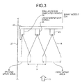
- FIG. 3 schematically depicts an atomized state of the CO 2 absorbent 14 sprayed from the spray nozzles 22A.
- the CO 2 absorber 15 has a square cross-sectional shape with respect to a flow direction of the flue gas 11. Accordingly, the number of liquid feed pipes can be increased by enlarging the cross-section in one direction without changing the arrangement of the nozzles, thereby enabling to increase the amount of processing gas and to easily realize scale-up of the CO 2 absorber 15.
- the spray nozzle 22A includes a liquid dispersion nozzle 25 and a wall-surface dedicated nozzle 26.
- the liquid dispersion nozzle 25 is provided inside of the wall-surface dedicated nozzle 26 in the CO 2 absorber 15.
- the wall-surface dedicated nozzle 26 is provided along the vicinity of a wall surface 27 in the CO 2 absorber 15.
- the vicinity of the wall surface 27 refers to a state where the wall-surface dedicated nozzle 26 does not come into contact with the wall surface 27 and there is a predetermined gap between the wall-surface dedicated nozzle 26 and the wall surface 27.
- the liquid dispersion nozzle 25 sprays the CO 2 absorbent 14 substantially uniformly in a square shape in the CO 2 absorber 15 (a first spray area A in FIGS. 2 and 3 ).
- the first spray area A of the CO 2 absorbent 14 sprayed from the liquid dispersion nozzle 25 overlaps on a part of the first spray area A of the CO 2 absorbent 14 sprayed from other adjacent liquid dispersion nozzles 25.
- the quantity of water of the CO 2 absorbent 14 sprayed from the liquid dispersion nozzle 25 decreases as moving away from the liquid dispersion nozzle 25. However, in an area in which the quantity of water of the CO 2 absorbent 14 sprayed from the liquid dispersion nozzle 25 decreases, because the CO 2 absorbent 14 overlaps with the CO 2 absorbent 14 sprayed from the other adjacent liquid dispersion nozzle 25, the quantity of water of the CO 2 absorbent 14 in the CO 2 absorber 15 can be maintained substantially uniform.
- the shape of the first spray area A of the CO 2 absorbent 14 sprayed from the liquid dispersion nozzle 25 is not limited to a square shape, and other shapes such as a circle and an elliptical shape can be also used.
- the wall-surface dedicated nozzle 26 sprays the CO 2 absorbent 14 toward inside of the CO 2 absorber 15.
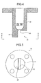
- FIG. 4 depicts a cross-sectional shape of the wall-surface dedicated nozzle 26 in a simplified manner
- FIG. 5 is a view from a direction of A-A in FIG. 4 .
- the wall-surface dedicated nozzle 26 includes a nozzle body 28 and a shield plate 29.
- the shield plate 29 is provided integral with the nozzle body 28 in an extended condition on a side of the wall surface 27 of the CO 2 absorber 15.
- the CO 2 absorbent 14 sprayed from a nozzle hole 30 of the wall-surface dedicated nozzle 26 hits the shield plate 29, and is sprayed to the inside of the CO 2 absorber 15 while suppressing that the CO 2 absorbent 14 is sprayed on the side of the wall surface 27 of the CO 2 absorber 15 (a second spray area B in FIGS. 2 and 3 ) .
- the CO 2 absorbent 14 can be sprayed substantially uniformly into the CO 2 absorber 15, and by providing the wall-surface dedicated nozzles 26 along the wall surface 27 of the CO 2 absorber 15, it is suppressed that the CO 2 absorbent 14 comes into contact with the wall surface 27 of the CO 2 absorber 15. Accordingly, the CO 2 absorbent 14 sprayed into the CO 2 absorber 15 can be dispersed up to the vicinity of the wall surface 27 of the CO 2 absorber 15, with the quantity of water thereof being maintained substantially uniform.
- FIG. 6 schematically depicts water quantity distribution of the CO 2 absorbent 14 in the direction of A-A in FIG. 2 at a cross-section of the CO 2 absorber 15.
- the density of water in the CO 2 absorber 15, because density of water is in a range equal to or more than 90% to equal to or less than 110%, the density of water can be maintained in a distribution range of 100% ( ⁇ 10%), and the density of water can be maintained about 90% even on the wall surface 27 of the CO 2 absorber 15.
- the quantity of water of the CO 2 absorbent 14 to be fed into the CO 2 absorber 15 can be made substantially uniform up to the vicinity of the wall surface 27 of the CO 2 absorber 15.
- the flue gas 11 passes through the CO 2 absorber 15 without coming into contact with the CO 2 absorbent 14. Furthermore, because the amount of the CO 2 absorber 15 sprayed onto the wall surface 27 of the CO 2 absorber 15 decreases, the amount of the CO 2 absorbent 14 stored at the bottom of the CO 2 absorber 15 without absorbing CO 2 in the flue gas 11 can be decreased.
- the CO 2 absorbent 14 can be dispersed substantially uniformly in the CO 2 absorber 15, and by providing the wall-surface dedicated nozzles 26 along the wall surface 27 of the CO 2 absorber 15, it can be suppressed that the CO 2 absorbent 14 comes into contact with the wall surface 27 of the CO 2 absorber 15. Therefore, the CO 2 absorbent 14 sprayed into the CO 2 absorber 15 can be dispersed, with the quantity of water thereof being made substantially uniform up to the vicinity of the wall surface 27 of the CO 2 absorber 15, regardless of the size of the CO 2 recovery unit 10 or the like.
- the material cost and manufacturing cost of the distributor, and the installation cost thereof in the CO 2 absorber 15 are reduced as compared with a case where the trough-type liquid distributor or the like is used, thereby enabling to decrease the facility cost of the gas-liquid contactor.
- Gaps between the respective nozzle holes of the liquid dispersion nozzle 25 and the wall-surface dedicated nozzle 26 are relatively different depending on the size of the respective nozzle holes and a flow rate and a spray area of the CO 2 absorbent 14 sprayed from the respective nozzle holes.
- the gaps between the respective nozzle holes of the liquid dispersion nozzle 25 and the wall-surface dedicated nozzle 26 can be set so that interference between the CO 2 absorbent 14 sprayed from the liquid dispersion nozzles 25 and the CO 2 absorbent 14 sprayed from the wall-surface dedicated nozzles 26 does not occur, for example, at the time of spraying, and the amount of the CO 2 absorbent 14 sprayed into the CO 2 absorber 15 becomes uniform.
- the spray nozzle 22A including the liquid dispersion nozzle 25 and the wall-surface dedicated nozzle 26 is used.
- a corner-part dedicated nozzle 31 can be provided at the corner part of the wall surface 27 of the CO 2 absorber 15.
- FIG. 8 depicts a cross-sectional shape of the corner-part dedicated nozzle 31 in a simplified manner.
- FIG. 9 is a view from a direction of A-A in FIG. 8 .
- the corner-part dedicated nozzle 31 includes a nozzle body 32, and an L-shaped shield plate 33 having an L-shaped cross-sectional shape in the longitudinal direction of the nozzle body 32.
- the L-shaped shield plate 33 is provided integral with the nozzle body 32 in an extended condition on the side of the wall surface 27 of the CO 2 absorber 15. Therefore, the CO 2 absorbent 14 sprayed from a nozzle hole 34 of the corner-part dedicated nozzle 31 hits both surfaces of the L-shaped shield plate 33, and is sprayed to the inside of the CO 2 absorber 15 while suppressing that the CO 2 absorbent 14 is sprayed to the corner side of the wall surface 27 of the CO 2 absorber 15 (a third spray area C in FIG. 7 ).
- the corner-part dedicated nozzle 31 sprays the CO 2 absorbent 14 to the inside of the CO 2 absorber 15, it can be suppressed that the CO 2 absorbent 14 sprayed from the corner-part dedicated nozzle 31 is dispersed to the corner part in a cross-section of the CO 2 absorber 15. Therefore, the CO 2 absorbent 14 can be dispersed uniformly up to the vicinity of the wall surface 27, and the amount of the CO 2 absorber 15 coming into contact with the wall surface 27 of the CO 2 absorber 15 can be decreased further. Accordingly, the amount of the CO 2 absorbent 14 stored at the bottom of the CO 2 absorber 15 without absorbing CO 2 in the flue gas 11 can be further decreased.
- FIGS. 10 and 11 are other configuration diagrams of the arrangement of the spray nozzles 22A.
- nozzles of different types can be provided as a short-side wall-surface dedicated nozzle 26a provided near the wall surface 27 on the short side of the CO 2 absorber 15 and a long-side wall-surface dedicated nozzle 26b provided near the wall surface 27 on the long side of the CO 2 absorber 15. Accordingly, the CO 2 absorbent 14 can be sprayed at an arbitrary ratio onto the short side and the long side of the CO 2 absorber 15.
- a result of a CO 2 recovery rate when the gas-liquid contactor 21A according to the present embodiment is applied to the CO 2 absorber 15 is shown in Table 1.
- Table 1 when a CO 2 absorption rate at the time of decreasing the amount to be sprayed onto the wall surface without arranging the wall-surface dedicated nozzle 26 is designated as a reference value (1.0), the CO 2 absorption rate becomes about 1.1 by arranging the wall-surface dedicated nozzle 26.
- the CO 2 absorption rate increases by applying the gas-liquid contactor 21A according to the present embodiment to the CO 2 absorber 15, the amount of the CO 2 absorbent 14 circulating in the CO 2 absorber 15 and the regenerator 17 decreases, thereby enabling to reduce the quantity of steam required for emitting CO 2 contained in the CO 2 absorbent 14 in the regenerator 17.
- the cross-sectional shape of the CO 2 absorber 15 with respect to the flow direction of the flue gas 11 is square.
- the cross-sectional shape of the CO 2 absorber 15 is not limited thereto, and it can be circular or elliptical.
- An atomizing pressure of the respective nozzles is set to equal to or lower than 0.2 megapascal, preferably equal to or lower than 0.15 megapascal, and more preferably equal to or lower than 0.1 megapascal.
- the CO 2 absorber 15 includes a water washing unit 42 and a demister 43 in an upper part of the CO 2 recovering unit 24.
- CO 2 -removed flue gas 41 of which CO 2 has been removed is emitted to outside of the system from a column top part, after the CO 2 absorbent 14 entrained by the CO 2 - removed flue gas 41 is removed by the water washing unit 42 and the demister 43.
- the rich solution 16 having absorbed CO 2 in the flue gas 11 in the CO 2 recovering unit 24 is stored at the bottom of the CO 2 absorber 15.
- the rich solution 16 stored at the bottom of the CO 2 absorber 15 is pressure-fed from a column bottom part of the CO 2 absorber 15 by a rich solvent pump 44 provided outside, heat-exchanged with the CO 2 absorbent 14 regenerated in the regenerator 17 in a rich-lean solution heat exchanger 45, and fed into the column from the column top part of the regenerator 17.
- the regenerator 17 regenerates the CO 2 absorbent 14 as the lean solution 14 by emitting CO 2 from the rich solution 16. Most part of CO 2 in the rich solution 16 emitted into the column of the regenerator 17 from the column top part of the regenerator 17 is emitted due to the endoergic reaction, and the rich solution 16 becomes the CO 2 absorbent (the lean solution) 14 in which almost all CO 2 is removed, when reaching the Column bottom part of the regenerator 17.
- the lean solution 14 stored at the bottom of the regenerator 17 is fed as a CO 2 absorbent by a lean solvent pump 46, cooled by heat exchange with cooling water 48 in a lean solvent cooler 47, and fed to the CO 2 absorber 15.
- CO 2 gas 51 accompanied by water vapor is emitted from the column top part of the regenerator 17.
- the CO 2 gas 51 accompanied by water vapor is derived from the column top part of the regenerator 17, water vapor contained in the CO 2 gas 51 is condensed by cooling water 53 in a capacitor 52.
- water 56 is separated in a separation drum 54, CO 2 gas 55 is emitted to outside of the system and recovered. Furthermore, the water 56 separated in the separation drum 54 is fed to the upper part of the regenerator 17 by a condensed-water circulation pump 57.
- the wall-surface dedicated nozzles 26 are provided along the vicinity of the wall surface 27 in the CO 2 absorber 15, and the liquid dispersion nozzles 25 are provided inside of the wall-surface dedicated nozzles 26.
- the CO 2 absorbent 14 is sprayed into the CO 2 absorber 15 from the liquid dispersion nozzles 25 and the wall-surface dedicated nozzles 26, the amount of the CO 2 absorbent 14 sprayed onto the wall surface 27 in the column is decreased.
- the CO 2 absorbent 14 is dispersed substantially uniformly up to the vicinity of the wall surface 27 in the CO 2 absorber 15, and the flue gas 11 fed into the column can be efficiently brought into contact with the CO 2 absorbent 14. Accordingly, the absorption performance of the CO 2 absorbent 14 for absorbing CO 2 can be improved, it can be suppressed that the flue gas 11 passes through the CO 2 absorber 15 without coming into contact with the CO 2 absorbent 14, and the facility cost can be reduced. Further, because the amount of the CO 2 absorbent 14 sprayed onto the wall surface 27 of the CO 2 absorber 15 can be reduced, the absorbed amount of CO 2 per amount of the CO 2 absorbent 14 fed to the CO 2 absorber 15 can be increased.
- the CO 2 absorbent 14 which does not absorb CO 2 in the flue gas 11 and is stored at the bottom of the CO 2 absorber 15, is fed to the regenerator 17, the CO 2 absorbent 14 can be used efficiently without wastefully consuming amine contained in the CO 2 absorbent 14, and steam required for emitting CO 2 contained in the CO 2 absorbent 14 in the regenerator 17 can be efficiently used without any waste. Consequently, the operation efficiency of the CO 2 recovery unit 10 can be increased.
- CO 2 in the flue gas 11 can be absorbed by the CO 2 absorbent 14 efficiently and stably, without being affected by the size of the CO 2 recovery unit 10 or the like.
- gas-liquid contactor according to the present embodiment is used for the CO 2 absorber 15 in the CO 2 recovery unit 10 is explained above.
- the present embodiment is not limited thereto, and for example, the gas-liquid contactor can be used in the cooling column 13 or the like.
- gas-liquid contactor is not limited to the case applied to the CO 2 recovery unit 10, and is applicable to any device having a spray nozzle to be used for spraying liquid downward to bring gas and liquid into contact with each other, such as a flue gas desulfurizer.
- a CO 2 recovery unit according to a second embodiment of the present invention in which a gas-liquid contactor is applied to a CO 2 absorber is explained below with reference to the drawings.
- the gas-liquid contactor according to the second embodiment is used as a CO 2 absorber as in the configuration of the CO 2 recovery unit shown in FIG. 1 .
- the configuration of the CO 2 recovery unit according to the present embodiment including the gas-liquid contactor is identical to that of the CO 2 recovery unit shown in FIG. 1 , a drawing of the configuration of the CO 2 recovery unit is omitted, and only a drawing of the configuration of the CO 2 absorber is used to explain the present embodiment.
- Constituent elements identical to those of the CO 2 recovery unit shown in FIG. 1 are denoted by like reference signs and explanations thereof will be omitted.
- FIG. 12 depicts a configuration of the gas-liquid contactor according to the second embodiment of the present invention in a simplified manner.
- a spray nozzle 22B of a gas-liquid contactor 21B according to the present embodiment includes two types of liquid dispersion nozzles 25 and wall-surface dedicated nozzles 26 that can be used according to the load operation of the CO 2 recovery unit 10.
- the two types of nozzles are alternately provided in a direction orthogonal to a gas flow direction of the flue gas 11 in the CO 2 absorber 15. That is, the liquid dispersion nozzle 25 includes a high-load liquid-dispersion nozzle 25A and a low-load liquid-dispersion nozzle 25B.
- the wall-surface dedicated nozzle 26 includes a high-load wall-surface dedicated nozzle 26A and a low-load wall-surface dedicated nozzle 26B.
- the high-load liquid-dispersion nozzles 25A and the low-load liquid-dispersion nozzles 25B are alternately provided in the direction orthogonal to the gas flow direction of the flue gas 11 in the CO 2 absorber 15.
- the high-load wall-surface dedicated nozzles 26A and the low-load wall-surface dedicated nozzles 26B are alternately provided on the wall surface 27 of the CO 2 absorber 15 in the direction orthogonal to the gas flow direction of the flue gas 11.
- An absorbent feed pipe 23a feeds the CO 2 absorbent 14 to the high-load liquid-dispersion nozzles 25A and the low-load liquid-dispersion nozzles 25B, and an absorbent feed pipe 23b feeds the CO 2 absorbent 14 to the high-load wall-surface dedicated nozzles 26A and the low-load wall-surface dedicated nozzles 26B.
- the CO 2 absorbent 14 can be sprayed from the same height in the column of the CO 2 absorber 15 by providing the high-load liquid-dispersion nozzles 25A and the high-load wall-surface dedicated nozzles 26A and the low-load liquid-dispersion nozzles 25B and the low-load wall-surface dedicated nozzles 26B in the CO 2 absorber 15.
- the gas-liquid contactor 21B uses the high-load liquid-dispersion nozzles 25A or the low-load liquid-dispersion nozzles 25B and uses the high-load wall-surface dedicated nozzles 26A or the low-load wall-surface dedicated nozzles 26B according to the load operation of the CO 2 recovery unit 10. Accordingly, the CO 2 absorbent 14 can be fed in an appropriate quantity of water into the CO 2 absorber 15 according to the load operation of the CO 2 recovery unit 10.
- the load operation of the CO 2 recovery unit 10 can be determined based on a flow rate of the flue gas 11 fed into the CO 2 absorber 15.
- the CO 2 absorbent 14 is sprayed from the high-load liquid-dispersion nozzles 25A and the high-load wall-surface dedicated nozzles 26A.
- the CO 2 absorbent 14 is sprayed from the low-load liquid-dispersion nozzles 25B and the low-load wall-surface dedicated nozzles 26B.
- FIG. 13 is an example of a relation between a flow rate and an atomizing pressure of a nozzle to be used. In FIG.
- the predetermined threshold is 55%.
- the low-load liquid-dispersion nozzles 25B and the low-load wall-surface dedicated nozzles 26B are used to spray the CO 2 absorbent 14 into the CO 2 absorber 15.
- the high-load liquid-dispersion nozzles 25A and the high-load wall-surface dedicated nozzles 26A are used to spray the CO 2 absorbent 14 into the CO 2 absorber 15.
- the atomizing pressure can be decreased under all load conditions and liquid can be dispersed uniformly. Accordingly, the amount of mist of the CO 2 absorbent 14 in the air caused by countercurrent contact between the flue gas 11 and the CO 2 absorbent 14 can be decreased.
- the pump power of the lean solvent pump 46 and the like required for feeding the CO 2 absorbent 14 into the CO 2 absorber 15 can be decreased.
- the predetermined threshold of the flow rate of the flue gas 11 for changing the use of the high-load liquid-dispersion nozzles 25A or the low-load liquid-dispersion nozzles 25B and the high-load wall-surface dedicated nozzles 26A or the low-load wall-surface dedicated nozzles 26B is set to 55% of the flow rate of the flue gas 11 as a reference.
- a case where the threshold of the flow rate of the flue gas 11 is 55% is explained above with reference to FIG. 13 .
- the present embodiment is not limited thereto, and the flow rate can be appropriately changed according to the size of the CO 2 recovery unit 10 or the CO 2 absorber 15, and an operating condition.
- the CO 2 absorbent 14 can be fed into the CO 2 absorber 15 corresponding to the load operation of the CO 2 recovery unit 10, thereby enabling to absorb CO 2 in the flue gas 11 by the CO 2 absorbent 14 more efficiently and stably.
- the load operation of the CO 2 recovery unit 10 is determined based on the flow rate of the flue gas 11 fed into the CO 2 absorber 15.
- the present embodiment is not limited thereto, and the load operation of the CO 2 recovery unit 10 can be determined based on the CO 2 recovery amount, the consumption power of an air blower, or an aperture of a damper.
- the high-load liquid-dispersion nozzles 25A and the low-load liquid-dispersion nozzles 25B are alternately provided in the direction orthogonal to the gas flow direction of the flue gas 11 in the CO 2 absorber 15.
- the present embodiment is not limited thereto, and after a plurality of high-load liquid-dispersion nozzles 25A are continuously provided in the direction orthogonal to the gas flow direction of the flue gas 11 in the CO 2 absorber 15, and then the low-load liquid-dispersion nozzles 25B can be provided.
- the high-load liquid-dispersion nozzles 25A and the high-load wall-surface dedicated nozzles 26A are used.
- the present embodiment is not limited thereto, and the low-load liquid-dispersion nozzles 25B and the low-load wall-surface dedicated nozzles 26B can be used, or the high-load liquid-dispersion nozzles 25A and the high-load wall-surface dedicated nozzles 26A, and the low-load liquid-dispersion nozzles 25B and the low-load wall-surface dedicated nozzles 26B can be used.
- the spray nozzle 22B is not limited thereto, and more than three types of the spray nozzles 22B including a medium-load nozzle in addition to the high-load nozzle and the low-load nozzle can be used.
- a CO 2 recovery unit according to a third embodiment of the present invention in which a gas-liquid contactor is applied to a CO 2 absorber is explained with reference to the drawings.
- the gas-liquid contactor according to the present embodiment is used as a CO 2 absorber of the CO 2 recovery unit shown in FIG. 1 , as in the gas-liquid contactor according to the second embodiment.
- the configuration of the CO 2 recovery unit according to the present embodiment in which the gas-liquid contactor is applied to the CO 2 absorber is identical to that of the CO 2 recovery unit shown in FIG. 1 , a drawing of the configuration of the CO 2 recovery unit is omitted, and only a drawing of a part of the configuration of the CO 2 absorber is used to explain the present embodiment.
- Constituent elements identical to those of the CO 2 recovery unit shown in FIG. 1 are denoted by like reference signs and explanations thereof will be omitted.
- FIG. 14 depicts a configuration of the gas-liquid contactor according to the third embodiment of the present invention in a simplified manner.
- the high-load liquid-dispersion nozzles 25A and the low-load liquid-dispersion nozzles 25B are alternately provided in the gas flow direction of the flue gas 11 in the CO 2 absorber 15, and the high-load wall-surface dedicated nozzles 26A and the low-load wall-surface dedicated nozzles 26B are alternately provided in the gas flow direction of the flue gas 11 near the wall surface 27 of the CO 2 absorber 15.
- the high-load liquid-dispersicn nozzles 25A and the low-load liquid-dispersion nozzles 25B are alternately provided in the direction orthogonal to the gas flow direction of the flue gas 11 in the CO 2 absorber 15, with arrangement positions of the respective nozzles being changed.
- the high-load wall-surface dedicated nozzles 26A and the low-load wall-surface dedicated nozzles 26B are alternately provided in the direction orthogonal to the gas flow direction of the flue gas 11 in the CO 2 absorber 15, with arrangement positions of the respective nozzles being changed.
- the high-load liquid-dispersion nozzles 25A and the low-load liquid-dispersion nozzles 25B are alternately provided in the gas flow direction of the flue gas 11 in the CO 2 absorber 15 and arrangement positions in the direction orthogonal to the gas flow direction of the flue gas 11 are changed, and the high-load wall-surface dedicated nozzles 26A and the low-load wall-surface dedicated nozzles 26B are alternately provided in the gas flow direction of the flue gas 11 in the CO 2 absorber 15 and arrangement positions in the direction orthogonal to the gas flow direction of the flue gas 11 are changed. Accordingly, the pressure loss of the flue gas 11 at the time of passing through the gas-liquid contactor according to the present embodiment can be decreased. Therefore, the power of the air blower required for feeding the flue gas 11 into the CO 2 absorber 15 can be decreased.
- the high-load liquid-dispersion nozzles 25A and the low-load liquid-dispersion nozzles 25B are provided alternately in the gas flow direction of the flue gas 11 in the CO 2 absorber 15, and the high-load wall-surface dedicated nozzles 26A and the low-load wall-surface dedicated nozzles 26B are provided alternately in the gas flow direction of the flue gas 11 on the wall surface 27 of the CO 2 absorber 15.
- the present embodiment is not limited thereto.
- the low-load liquid-dispersion nozzles 25B or the low-load wall-surface dedicated nozzles 26B can be provided.
- the pressure loss of the flue gas 11 to be fed to the CO 2 absorber 15 can be decreased, thereby enabling to absorb CO 2 in the flue gas 11 into the CO 2 absorbent 14 more efficiently and stably corresponding to the load operation of the CO 2 recovery unit 10, while decreasing the power required for feeding the flue gas 11 into the CO 2 absorber 15.
- CO 2 recovery unit 11 flue gas 12, 43, 56 water 13 cooling column 14 CO 2 absorbent 15 CO 2 absorber 16 rich solution 17 regenerator 18, 45, 48, 53 cooling water 19 flue gas duct 20 feed port 21A to 21C gas-liquid contactor 22A to 22C spray nozzle 23, 23a, 23b absorbent feed pipe 24 CO 2 recovering unit 25 liquid dispersion nozzle 25A high-load liquid-dispersion nozzle 25B low-load liquid-dispersion nozzle 26 wall-surface dedicated nozzle 26a short-side wall-surface dedicated nozzle 26b long-side wall-surface dedicated nozzle 62A high-load wall-surface dedicated nozzle 62B low-load wall-surface dedicated nozzle 27 wall surface 28, 32 nozzle body 29 shield plate 30, 34 nozzle hole 31 corner-part dedicated nozzle 33 L-shaped shield plate 41 CO 2 -removed flue gas 42 water washing unit 43 demister 44 rich solvent pump 45 rich-lean solution heat exchanger 46 lean solvent pump 47 lean solvent cooler 51, 55 CO 2 gas 52 capacitor 54
Landscapes
- Chemical & Material Sciences (AREA)
- Chemical Kinetics & Catalysis (AREA)
- Organic Chemistry (AREA)
- Engineering & Computer Science (AREA)
- Analytical Chemistry (AREA)
- General Chemical & Material Sciences (AREA)
- Oil, Petroleum & Natural Gas (AREA)
- Inorganic Chemistry (AREA)
- Gas Separation By Absorption (AREA)
- Treating Waste Gases (AREA)
- Carbon And Carbon Compounds (AREA)
Abstract
Description
- The present invention relates to a gas-liquid contactor that supplies a processing liquid to a packed column in which absorption and distillation are performed by gas-liquid contact, and more particularly to a gas-liquid contactor such as a CO2 absorber that absorbs CO2 in flue gas and a CO2 recovery unit.
- In a packed column provided with a packed bed in which a component contained in gas is absorbed into liquid by gas-liquid contact to perform absorptive processing, it is essential to disperse the liquid into the column uniformly. The dispersion largely affects the performance of a packing material, that is, the processing performance of the packed column. Therefore, it is particularly important to disperse liquid uniformly and densely and bring liquid and gas into contact with each other.
- For example, in thermal power plants using a large amount of fossil fuel, a method of removing and recovering CO2 in flue gas and a method of storing recovered CO2 without emitting CO2 into the air by bringing flue gas generated due to burning of fossil fuel in a boiler into gas-liquid contact with an amine CO2 absorbent in a CO2 absorber to absorb CO2 have been vigorously researched. Such a method has been used that CO2 in flue gas is absorbed by the CO2 absorbent in the CO2 absorber, and after CO2 is removed from flue gas, CO2 absorbed by the CO2 absorbent is diffused in a regenerator to regenerate the CO2 absorbent, which is then circulated again to the CO2 absorber and reused (see, for example, Patent Literature 1).
- In a gas absorber such as the CO2 absorber in which flue gas having a gas form is brought into contact with the CO2 absorbent having the form of a liquid, the gas-liquid contact efficiency of gas and liquid in the gas absorber largely affects the processing performance of the gas in the gas absorber. Therefore, at the time of spraying liquid into the gas absorber, liquid needs to be brought into contact with gas efficiently. In the gas absorber, a liquid distributor that sprays liquid from an upper part of the column is used, and as a method of dispersing liquid in the gas absorber, for example, a spray-type liquid distributor (see, for example, Patent Literatures 2 and 3), a trough-type liquid distributor (see, for example, Non Patent Literature 1), and a channel-type liquid distributor that distributes liquid by an amount different from each other, an element-type liquid distributor, and a tubular liquid distributor can be used.
-
- Patent Literature 1: Japanese Patent Application Laid-open No.
2008-62165 - Patent Literature 2: Japanese Patent Application Laid-open No.
2001-9237 - Patent Literature 3: Japanese Patent No.
2506351 -
- Non Patent Literature 1: Edited by Kakusaburo ONDA, "Chemical equipment design and operation series No. 2, Revised, Gas absorption", Kagaku Kogyo Sha, January 30, 2001, p. 138
- When a spray-type liquid distributor is used in the gas absorber, a plurality of nozzles are provided in the gas absorber so that liquid is uniformly dispersed into the gas absorber by overlapping liquid spray areas with each other.
- However, the distribution of a liquid to be into the column becomes lower near a wall surface of the gas absorber than inside of the gas absorber, and thus there is a problem that the absorption performance of liquid for absorbing a component contained in gas is degraded near the wall surface in the column.
- Particularly, when the gas absorber is a CO2 absorber, at the time of absorbing CO2 contained in flue gas by the CO2 absorbent, because a feed amount of the CO2 absorbent is lower near the wall surface of the CO2 absorber than inside of the column, the gas absorption performance of the CO2 absorbent for absorbing CO2, which is sprayed to near the wall surface of the CO2 absorber, is degraded. Furthermore, if the amount of a CO2 absorbent sprayed to the wall surface of the CO2 absorber is large, an absorbed amount of CO2 per amount of a CO2 absorbent fed to the CO2 absorber decreases. If the CO2 absorbent, which has not absorbed CO2 contained in flue gas, is fed to the regenerator, amine contained in the CO2 absorbent is wastefully consumed, and the CO2 absorbent is not efficiently used. Further, the amount of steam required for emitting CO2 contained in the CO2 absorbent in the regenerator increases, thereby degrading the operation efficiency of the CO2 recovery unit.
- Furthermore, when the spray-type liquid distributor is used in the gas absorber, a flow rate thereof can be changed according to an operation load. However, because the flow rate is proportional to an atomizing pressure, the spray atomizing pressure in a high flow rate region needs to be increased in order to accommodate from a lcw flow rate region to the high flow rate region, thereby causing a problem that if the spray atomizing pressure is high, the amount of mist in the air increases. Particularly, when the gas absorber is the CO2 absorber, when CO2 contained in flue gas is absorbed by the CO2 absorbent, the CO2 absorbent is entrained by flue gas, from which CO2 has been recovered, thereby degrading the operation efficiency of the CO2 recovery unit.
- Further, when a trough-type liquid distributor is used in the gas absorber, the height of the distributor needs to be increased in order to perform a load operation according to a gas processing amount. Therefore, the material cost and manufacturing cost of the distributor, and the installation cost thereof in the gas absorber increase, and this leads to an increase of the facility cost.
- The present invention has been achieved to solve the above problems, and an object of the present invention is to provide a gas-liquid contactor and a CO2 recovery unit that can bring gas and liquid fed to a column into contact with each other efficiently and can realize cost reduction by dispersing liquid substantially uniformly in the column and decreasing the amount of liquid to be sprayed onto a wall surface in the column.
- According to a first aspect of the present invention in order to solve the above problems, there is provided a gas-liquid contactor that sprays liquid downward into a contact column in which gas drifts upward and passes to bring the gas drifting upward and the liquid into contact with each other, the gas-liquid contactor including: a wall-surface dedicated nozzle provided along a wall surface in the contact column to spray the liquid toward inside of the contact column; and a liquid dispersion nozzle provided inside of the wall-surface dedicated nozzle in the contact column to uniformly spray the liquid into the contact column.
- According to a second aspect of the present invention, there is provided the gas-liquid contactor according to the first aspect, wherein a cross-sectional shape of the contact column in a direction orthogonal to the flow direction of the gas is square.
- According to a third aspect of the present invention, there is provided the gas-liquid contactor according to the second aspect, including a corner-part dedicated nozzle provided at the corner part in section of the contact column to spray the liquid toward inside of the contact column.
- According to a fourth aspect of the present invention, there is provided the gas-liquid contactor according to any one of the first to third aspects, wherein the liquid dispersion nozzle and the wall-surface dedicated nozzle include two or more types of nozzles, which are used according to a flow rate of the gas.
- According to a fifth aspect of the present invention, there is provided the gas-liquid contactor according to the fourth aspect, wherein the liquid dispersion nozzle includes a high-load liquid-dispersion nozzle and a low-load liquid-dispersion nozzle, and the wall-surface dedicated nozzle includes a high-load wall-surface dedicated nozzle and a low-load wall-surface dedicated nozzle, and when the flow rate of the gas is equal to or higher than a predetermined threshold, the liquid is sprayed from the high-load liquid-dispersion nozzle and the high-load wall-surface dedicated nozzle, and when the flow rate of the gas is lower than the predetermined threshold, the liquid is sprayed from the low-load liquid-dispersion nozzle and the low-load wall-surface dedicated nozzle.
- According to a sixth aspect of the present invention, there is provided the gas-liquid contactor according to the fourth or fifth aspect, wherein liquid dispersion nozzles and wall-surface dedicated nozzles of different types are alternately provided in the direction orthogonal to the flow direction of the gas in the contact column.
- According to a seventh aspect of the present invention, there is provided the gas-liquid contactor according to the sixth aspect, where the liquid dispersion nozzles and the wall-surface dedicated nozzles of different types are alternately provided in the flow direction of the gas in the contact column with arrangement positions of the respective nozzles being changed.
- According to an eighth aspect of the present invention, there is provided a CO2 recovery unit including: a CO2 absorber that includes the contact column of the gas-liquid contactor according to any one of claims 1 to 7, and, by bringing flue gas containing CO2 into contact with a CO2 absorbent, that absorbs CO2 to remove CO2 from the flue gas; and a regenerator that emits CO2 from the CO2 absorbent having absorbed CO2 to regenerate the CO2 absorbent.
- According to the gas-liquid contactor of the present invention, the gas-liquid contactor allows gas and liquid fed into a column to contact with each other efficiently and to realize cost reduction by dispersing liquid substantially uniformly in the column and decreasing the amount of liquid to be sprayed onto a wall surface in the column.
- When a gas absorber is a CO2 absorber, at the time of absorbing CO2 contained in flue gas by the CO2 absorbent, because a feed amount of the CO2 absorbent can be made substantially uniform up to the vicinity of the wall surface of the CO2 absorber, the absorption performance of the CO2 absorbent for absorbing CO2 can be improved. Furthermore, because the amount of the CO2 absorbent sprayed onto the wall surface of the CO2 absorber can be decreased, an absorbed amount of CO2 per amount of the CO2 absorbent fed to the CO2 absorber can be increased.
- By decreasing the CO2 absorbent, which has not absorbed CO2 contained in flue gas, to be fed to the regenerator, the CO2 absorbent can be efficiently used without wastefully consuming amine contained in the CO2 absorbent, and steam required for emitting CO2 contained in the CO2 absorbent in the regenerator can be used efficiently without any waste, thereby enabling to improve the operation efficiency of the CO2 recovery unit.
-
-
FIG. 1 depicts a configuration of a CO2 recovery unit according to a first embodiment of the present invention including a gas-liquid contactor in a simplified manner. -
FIG. 2 depicts an arrangement of spray nozzles in a simplified manner. -
FIG. 3 schematically depicts an atomized state of a CO2 absorbent sprayed from the spray nozzles. -
FIG. 4 depicts a cross-sectional shape of a wall-surface dedicated nozzle in a simplified manner. -
FIG. 5 is a view from a direction of A-A inFIG. 4 . -
FIG. 6 schematically depicts water quantity distribution of a CO2 absorbent in the direction of A-A inFIG. 2 at a cross-section of a CO2 absorber. -
FIG. 7 depicts another configuration of the arrangement of the spray nozzles in a simplified manner. -
FIG. 8 depicts a cross-sectional shape of a corner-part dedicatednozzle 31 in a simplified manner. -
FIG. 9 is a view from a direction of A-A inFIG. 8 . -
FIG. 10 is another configuration diagram of the arrangement of the spray nozzles in a simplified manner. -
FIG. 11 is another configuration diagram of the arrangement of the spray nozzles in a simplified manner. -
FIG. 12 depicts a configuration of a gas-liquid contactor according to a second embodiment of the present invention in a simplified manner. -
FIG. 13 is an example of a relation between a flow rate and an atomizing pressure. -
FIG. 14 depicts a configuration of a gas-liquid contactor according to a third embodiment of the present invention in a simplified manner. - The present invention is explained below in detail with reference to the accompanying drawings. The present invention is not limited to the modes for carrying out the invention (hereinafter, "embodiments"). Furthermore, constituent elements in the following embodiments include those that can be easily assumed by persons skilled in the art, that are substantially equivalent, and so-called equivalents. In addition, constituent elements in the following embodiments disclosed in the following embodiments can be combined as appropriate.
- A CO2 recovery unit in which a gas-liquid contactor according to a first embodiment of the present invention is applied to a CO2 absorber is explained with reference to the drawings.
FIG. 1 depicts a configuration of a CO2 recovery unit according to the first embodiment of the present invention including a gas-liquid contactor in a simplified manner. As shown inFIG. 1 , a CO2 recovery unit 10 includes acooling column 13 that coolsflue gas 11 containing CO2 bywater 12, a CO2 absorber 15 that brings the cooledflue gas 11 into contact with a CO2 absorbent 14 that absorbs CO2, thereby removing CO2 from theflue gas 11, and aregenerator 17 that causes CO2 to be emitted from a CO2 absorbent (a rich solution) 16 having absorbed CO2, thereby regenerating the CO2 absorbent 14. - In the CO2 recovery unit 10, the CO2 absorbent 14 circulates between the CO2 absorber 15 and the
regenerator 17, the CO2 absorbent (the rich solution) 16 having absorbed CO2 is fed from the CO2 absorber 15 to theregenerator 17, and the regenerated CO2 absorbent (a lean solution) 14 in which almost all CO2 has been removed from therich solution 16 in theregenerator 17 is fed from theregenerator 17 to the CO2 absorber 15. - After the
flue gas 11 containing CO2 discharged from an industrial facility such as a boiler or a gas turbine is boosted by a flue gas blower or the like, theflue gas 11 is fed to thecooling column 13 and is cooled due to countercurrent contact with thewater 12 in thecooling column 13. Thewater 12 having a high temperature due to heat exchange with theflue gas 11 is extracted from the bottom of thecooling column 13 and is cooled by coolingwater 18, and is circulated and used for cooling theflue gas 11. The cooledflue gas 11 is discharged from thecooling column 13 through aflue gas duct 19 that connects thecooling column 13 to the CO2 absorber 15. Theflue gas 11 discharged from thecooling column 13 passes through theflue gas duct 19, and is fed to the CO2 absorber 15 from afeed port 20 provided on a side wall at the bottom of the CO2 absorber 15. - The CO2 absorber 15 includes a gas-
liquid contactor 21A that sprays the CO2 absorbent 14 downward into the CO2 absorber 15, in which theflue gas 11 drifts upward and passes therein, thereby bringing theflue gas 11 drifting upward into contact with the CO2 absorbent 14. The gas-liquid contactor 21A includesspray nozzles 22A that sprays the CO2 absorbent 14 into the CO2 absorber 15, and anabsorbent feed pipe 23 for feeding the CO2 absorbent 14 to therespective spray nozzles 22A. - In the CO2 absorber 15, in a CO2 recovering unit 24 provided in a lower part of the CO2 absorber 15, the
flue gas 11 comes into countercurrent contact with the CO2 absorbent 14 containing a basic amine compound as a base, for example, and CO2 in theflue gas 11 is absorbed by the CO2 absorbent 14. -
FIG. 2 depicts an arrangement of thespray nozzles 22A in a simplified manner.FIG. 3 schematically depicts an atomized state of the CO2 absorbent 14 sprayed from thespray nozzles 22A. As shown inFIGS. 2 and3 , the CO2 absorber 15 has a square cross-sectional shape with respect to a flow direction of theflue gas 11. Accordingly, the number of liquid feed pipes can be increased by enlarging the cross-section in one direction without changing the arrangement of the nozzles, thereby enabling to increase the amount of processing gas and to easily realize scale-up of the CO2 absorber 15. - The
spray nozzle 22A includes aliquid dispersion nozzle 25 and a wall-surfacededicated nozzle 26. Theliquid dispersion nozzle 25 is provided inside of the wall-surfacededicated nozzle 26 in the CO2 absorber 15. The wall-surfacededicated nozzle 26 is provided along the vicinity of awall surface 27 in the CO2 absorber 15. The vicinity of thewall surface 27 refers to a state where the wall-surfacededicated nozzle 26 does not come into contact with thewall surface 27 and there is a predetermined gap between the wall-surfacededicated nozzle 26 and thewall surface 27. Theliquid dispersion nozzle 25 sprays the CO2 absorbent 14 substantially uniformly in a square shape in the CO2 absorber 15 (a first spray area A inFIGS. 2 and3 ). The first spray area A of the CO2 absorbent 14 sprayed from theliquid dispersion nozzle 25 overlaps on a part of the first spray area A of the CO2 absorbent 14 sprayed from other adjacentliquid dispersion nozzles 25. The quantity of water of the CO2 absorbent 14 sprayed from theliquid dispersion nozzle 25 decreases as moving away from theliquid dispersion nozzle 25. However, in an area in which the quantity of water of the CO2 absorbent 14 sprayed from theliquid dispersion nozzle 25 decreases, because the CO2 absorbent 14 overlaps with the CO2 absorbent 14 sprayed from the other adjacentliquid dispersion nozzle 25, the quantity of water of the CO2 absorbent 14 in the CO2 absorber 15 can be maintained substantially uniform. The shape of the first spray area A of the CO2 absorbent 14 sprayed from theliquid dispersion nozzle 25 is not limited to a square shape, and other shapes such as a circle and an elliptical shape can be also used. - The wall-surface
dedicated nozzle 26 sprays the CO2 absorbent 14 toward inside of the CO2 absorber 15.FIG. 4 depicts a cross-sectional shape of the wall-surfacededicated nozzle 26 in a simplified manner, andFIG. 5 is a view from a direction of A-A inFIG. 4 . As shown inFIGS. 4 and 5 , the wall-surfacededicated nozzle 26 includes anozzle body 28 and ashield plate 29. Theshield plate 29 is provided integral with thenozzle body 28 in an extended condition on a side of thewall surface 27 of the CO2 absorber 15. Therefore, the CO2 absorbent 14 sprayed from anozzle hole 30 of the wall-surfacededicated nozzle 26 hits theshield plate 29, and is sprayed to the inside of the CO2 absorber 15 while suppressing that the CO2 absorbent 14 is sprayed on the side of thewall surface 27 of the CO2 absorber 15 (a second spray area B inFIGS. 2 and3 ) . - Conventionally, because the surface formed by overlapping CO2 absorbent 14 spray areas in the CO2 absorber 15 is large, a feed rate of the CO2 absorbent 14 is lower near the wall surface of the CO2 absorber 15 than inside of the absorber. Therefore, when CO2 contained in the
flue gas 11 is absorbed by the CO2 absorbent 14, the gas absorption performance of the CO2 absorbent 14 for absorbing CO2 sprayed to near the wall surface of the CO2 absorber 15 is degraded. Furthermore, if the amount of a CO2 absorbent sprayed to the wall surface of the CO2 absorber is large, an absorbed amount of CO2 per amount of the CO2 absorbent 14 fed to the CO2 absorber 15 decreases, and the CO2 absorbent 14 is not efficiently used. On the other hand, in the present embodiment, as shown inFIGS. 2 and3 , by providing theliquid dispersion nozzles 25 in the CO2 absorber 15, the CO2 absorbent 14 can be sprayed substantially uniformly into the CO2 absorber 15, and by providing the wall-surfacededicated nozzles 26 along thewall surface 27 of the CO2 absorber 15, it is suppressed that the CO2 absorbent 14 comes into contact with thewall surface 27 of the CO2 absorber 15. Accordingly, the CO2 absorbent 14 sprayed into the CO2 absorber 15 can be dispersed up to the vicinity of thewall surface 27 of the CO2 absorber 15, with the quantity of water thereof being maintained substantially uniform. -
FIG. 6 schematically depicts water quantity distribution of the CO2 absorbent 14 in the direction of A-A inFIG. 2 at a cross-section of the CO2 absorber 15. As shown inFIG. 6 , in the CO2 absorber 15, because density of water is in a range equal to or more than 90% to equal to or less than 110%, the density of water can be maintained in a distribution range of 100% (±10%), and the density of water can be maintained about 90% even on thewall surface 27 of the CO2 absorber 15. The quantity of water of the CO2 absorbent 14 to be fed into the CO2 absorber 15 can be made substantially uniform up to the vicinity of thewall surface 27 of the CO2 absorber 15. Therefore, it can be suppressed that theflue gas 11 passes through the CO2 absorber 15 without coming into contact with the CO2 absorbent 14. Furthermore, because the amount of the CO2 absorber 15 sprayed onto thewall surface 27 of the CO2 absorber 15 decreases, the amount of the CO2 absorbent 14 stored at the bottom of the CO2 absorber 15 without absorbing CO2 in theflue gas 11 can be decreased. - Accordingly, by providing the
liquid dispersion nozzles 25 in the CO2 absorber 15, the CO2 absorbent 14 can be dispersed substantially uniformly in the CO2 absorber 15, and by providing the wall-surfacededicated nozzles 26 along thewall surface 27 of the CO2 absorber 15, it can be suppressed that the CO2 absorbent 14 comes into contact with thewall surface 27 of the CO2 absorber 15. Therefore, the CO2 absorbent 14 sprayed into the CO2 absorber 15 can be dispersed, with the quantity of water thereof being made substantially uniform up to the vicinity of thewall surface 27 of the CO2 absorber 15, regardless of the size of the CO2 recovery unit 10 or the like. - Because the CO2 absorbent 14 is fed to the
liquid dispersion nozzles 25 and the wall-surfacededicated nozzles 26 via theabsorbent feed pipe 23, the material cost and manufacturing cost of the distributor, and the installation cost thereof in the CO2 absorber 15 are reduced as compared with a case where the trough-type liquid distributor or the like is used, thereby enabling to decrease the facility cost of the gas-liquid contactor. - Gaps between the respective nozzle holes of the
liquid dispersion nozzle 25 and the wall-surfacededicated nozzle 26 are relatively different depending on the size of the respective nozzle holes and a flow rate and a spray area of the CO2 absorbent 14 sprayed from the respective nozzle holes. The gaps between the respective nozzle holes of theliquid dispersion nozzle 25 and the wall-surfacededicated nozzle 26 can be set so that interference between the CO2 absorbent 14 sprayed from theliquid dispersion nozzles 25 and the CO2 absorbent 14 sprayed from the wall-surfacededicated nozzles 26 does not occur, for example, at the time of spraying, and the amount of the CO2 absorbent 14 sprayed into the CO2 absorber 15 becomes uniform. - The
spray nozzle 22A including theliquid dispersion nozzle 25 and the wall-surfacededicated nozzle 26 is used. However, the present embodiment is not limited thereto. As shown inFIG. 7 , a corner-partdedicated nozzle 31 can be provided at the corner part of thewall surface 27 of the CO2 absorber 15.FIG. 8 depicts a cross-sectional shape of the corner-partdedicated nozzle 31 in a simplified manner.FIG. 9 is a view from a direction of A-A inFIG. 8 . As shown inFIGS. 8 and 9 , the corner-partdedicated nozzle 31 includes anozzle body 32, and an L-shapedshield plate 33 having an L-shaped cross-sectional shape in the longitudinal direction of thenozzle body 32. The L-shapedshield plate 33 is provided integral with thenozzle body 32 in an extended condition on the side of thewall surface 27 of the CO2 absorber 15. Therefore, the CO2 absorbent 14 sprayed from anozzle hole 34 of the corner-partdedicated nozzle 31 hits both surfaces of the L-shapedshield plate 33, and is sprayed to the inside of the CO2 absorber 15 while suppressing that the CO2 absorbent 14 is sprayed to the corner side of thewall surface 27 of the CO2 absorber 15 (a third spray area C inFIG. 7 ). Accordingly, because the corner-partdedicated nozzle 31 sprays the CO2 absorbent 14 to the inside of the CO2 absorber 15, it can be suppressed that the CO2 absorbent 14 sprayed from the corner-partdedicated nozzle 31 is dispersed to the corner part in a cross-section of the CO2 absorber 15. Therefore, the CO2 absorbent 14 can be dispersed uniformly up to the vicinity of thewall surface 27, and the amount of the CO2 absorber 15 coming into contact with thewall surface 27 of the CO2 absorber 15 can be decreased further. Accordingly, the amount of the CO2 absorbent 14 stored at the bottom of the CO2 absorber 15 without absorbing CO2 in theflue gas 11 can be further decreased. - As the wall-surface
dedicated nozzles 26, the same nozzle is provided near thewall surface 27 on a short side and a long side of the CO2 absorber 15. However, the present embodiment is not limited thereto.FIGS. 10 and11 are other configuration diagrams of the arrangement of thespray nozzles 22A. As shown inFIGS. 10 and11 , as the wall-surfacededicated nozzle 26, nozzles of different types can be provided as a short-side wall-surfacededicated nozzle 26a provided near thewall surface 27 on the short side of the CO2 absorber 15 and a long-side wall-surfacededicated nozzle 26b provided near thewall surface 27 on the long side of the CO2 absorber 15. Accordingly, the CO2 absorbent 14 can be sprayed at an arbitrary ratio onto the short side and the long side of the CO2 absorber 15. - A result of a CO2 recovery rate when the gas-
liquid contactor 21A according to the present embodiment is applied to the CO2 absorber 15 is shown in Table 1. As shown in Table 1, when a CO2 absorption rate at the time of decreasing the amount to be sprayed onto the wall surface without arranging the wall-surfacededicated nozzle 26 is designated as a reference value (1.0), the CO2 absorption rate becomes about 1.1 by arranging the wall-surfacededicated nozzle 26. Accordingly, because the CO2 absorption rate increases by applying the gas-liquid contactor 21A according to the present embodiment to the CO2 absorber 15, the amount of the CO2 absorbent 14 circulating in the CO2 absorber 15 and theregenerator 17 decreases, thereby enabling to reduce the quantity of steam required for emitting CO2 contained in the CO2 absorbent 14 in theregenerator 17. -
Table 1 Without wall-surface dedicated nozzle 26Wich wall-surface dedicated nozzle 26Race of CO2 absorption 1.0 1.1 - The cross-sectional shape of the CO2 absorber 15 with respect to the flow direction of the
flue gas 11 is square. However, the cross-sectional shape of the CO2 absorber 15 is not limited thereto, and it can be circular or elliptical. - An atomizing pressure of the respective nozzles is set to equal to or lower than 0.2 megapascal, preferably equal to or lower than 0.15 megapascal, and more preferably equal to or lower than 0.1 megapascal. By decreasing the nozzle atomizing pressure, the pump power consumption can be decreased, and a mist scattering amount can be suppressed.
- The CO2 absorber 15 includes a
water washing unit 42 and ademister 43 in an upper part of the CO2 recovering unit 24. CO2-removed flue gas 41 of which CO2 has been removed is emitted to outside of the system from a column top part, after the CO2 absorbent 14 entrained by the CO2 - removedflue gas 41 is removed by thewater washing unit 42 and thedemister 43. Therich solution 16 having absorbed CO2 in theflue gas 11 in the CO2 recovering unit 24 is stored at the bottom of the CO2 absorber 15. Therich solution 16 stored at the bottom of the CO2 absorber 15 is pressure-fed from a column bottom part of the CO2 absorber 15 by a rich solvent pump 44 provided outside, heat-exchanged with the CO2 absorbent 14 regenerated in theregenerator 17 in a rich-leansolution heat exchanger 45, and fed into the column from the column top part of theregenerator 17. - The
regenerator 17 regenerates the CO2 absorbent 14 as thelean solution 14 by emitting CO2 from therich solution 16. Most part of CO2 in therich solution 16 emitted into the column of the regenerator 17 from the column top part of theregenerator 17 is emitted due to the endoergic reaction, and therich solution 16 becomes the CO2 absorbent (the lean solution) 14 in which almost all CO2 is removed, when reaching the Column bottom part of theregenerator 17. Thelean solution 14 stored at the bottom of theregenerator 17 is fed as a CO2 absorbent by a leansolvent pump 46, cooled by heat exchange with coolingwater 48 in a leansolvent cooler 47, and fed to the CO2 absorber 15. Meanwhile, CO2 gas 51 accompanied by water vapor is emitted from the column top part of theregenerator 17. The CO2 gas 51 accompanied by water vapor is derived from the column top part of theregenerator 17, water vapor contained in the CO2 gas 51 is condensed by coolingwater 53 in acapacitor 52. Afterwater 56 is separated in aseparation drum 54, CO2 gas 55 is emitted to outside of the system and recovered. Furthermore, thewater 56 separated in theseparation drum 54 is fed to the upper part of theregenerator 17 by a condensed-water circulation pump 57. - As described above, according to the CO2 recovery unit 10 in which the gas-liquid contactor according to the present embodiment is used for the CO2 absorber 15, the wall-surface
dedicated nozzles 26 are provided along the vicinity of thewall surface 27 in the CO2 absorber 15, and theliquid dispersion nozzles 25 are provided inside of the wall-surfacededicated nozzles 26. When the CO2 absorbent 14 is sprayed into the CO2 absorber 15 from theliquid dispersion nozzles 25 and the wall-surfacededicated nozzles 26, the amount of the CO2 absorbent 14 sprayed onto thewall surface 27 in the column is decreased. Furthermore, the CO2 absorbent 14 is dispersed substantially uniformly up to the vicinity of thewall surface 27 in the CO2 absorber 15, and theflue gas 11 fed into the column can be efficiently brought into contact with the CO2 absorbent 14. Accordingly, the absorption performance of the CO2 absorbent 14 for absorbing CO2 can be improved, it can be suppressed that theflue gas 11 passes through the CO2 absorber 15 without coming into contact with the CO2 absorbent 14, and the facility cost can be reduced. Further, because the amount of the CO2 absorbent 14 sprayed onto thewall surface 27 of the CO2 absorber 15 can be reduced, the absorbed amount of CO2 per amount of the CO2 absorbent 14 fed to the CO2 absorber 15 can be increased. Accordingly, by suppressing that the CO2 absorbent 14, which does not absorb CO2 in theflue gas 11 and is stored at the bottom of the CO2 absorber 15, is fed to theregenerator 17, the CO2 absorbent 14 can be used efficiently without wastefully consuming amine contained in the CO2 absorbent 14, and steam required for emitting CO2 contained in the CO2 absorbent 14 in theregenerator 17 can be efficiently used without any waste. Consequently, the operation efficiency of the CO2 recovery unit 10 can be increased. - Accordingly, in the CO2 recovery unit 10 in which the gas-liquid contactor according to the present embodiment is applied to the CO2 absorber 15, CO2 in the
flue gas 11 can be absorbed by the CO2 absorbent 14 efficiently and stably, without being affected by the size of the CO2 recovery unit 10 or the like. - A case where the gas-liquid contactor according to the present embodiment is used for the CO2 absorber 15 in the CO2 recovery unit 10 is explained above. However, the present embodiment is not limited thereto, and for example, the gas-liquid contactor can be used in the
cooling column 13 or the like. - Furthermore, the gas-liquid contactor according to the present embodiment is not limited to the case applied to the CO2 recovery unit 10, and is applicable to any device having a spray nozzle to be used for spraying liquid downward to bring gas and liquid into contact with each other, such as a flue gas desulfurizer.
- A CO2 recovery unit according to a second embodiment of the present invention in which a gas-liquid contactor is applied to a CO2 absorber is explained below with reference to the drawings. In the present embodiment, the gas-liquid contactor according to the second embodiment is used as a CO2 absorber as in the configuration of the CO2 recovery unit shown in
FIG. 1 . Because the configuration of the CO2 recovery unit according to the present embodiment including the gas-liquid contactor is identical to that of the CO2 recovery unit shown inFIG. 1 , a drawing of the configuration of the CO2 recovery unit is omitted, and only a drawing of the configuration of the CO2 absorber is used to explain the present embodiment. Constituent elements identical to those of the CO2 recovery unit shown inFIG. 1 are denoted by like reference signs and explanations thereof will be omitted. -
FIG. 12 depicts a configuration of the gas-liquid contactor according to the second embodiment of the present invention in a simplified manner. As shown inFIG. 12 , aspray nozzle 22B of a gas-liquid contactor 21B according to the present embodiment includes two types ofliquid dispersion nozzles 25 and wall-surfacededicated nozzles 26 that can be used according to the load operation of the CO2 recovery unit 10. The two types of nozzles are alternately provided in a direction orthogonal to a gas flow direction of theflue gas 11 in the CO2 absorber 15. That is, theliquid dispersion nozzle 25 includes a high-load liquid-dispersion nozzle 25A and a low-load liquid-dispersion nozzle 25B. The wall-surfacededicated nozzle 26 includes a high-load wall-surfacededicated nozzle 26A and a low-load wall-surfacededicated nozzle 26B. The high-load liquid-dispersion nozzles 25A and the low-load liquid-dispersion nozzles 25B are alternately provided in the direction orthogonal to the gas flow direction of theflue gas 11 in the CO2 absorber 15. The high-load wall-surfacededicated nozzles 26A and the low-load wall-surfacededicated nozzles 26B are alternately provided on thewall surface 27 of the CO2 absorber 15 in the direction orthogonal to the gas flow direction of theflue gas 11.
Anabsorbent feed pipe 23a feeds the CO2 absorbent 14 to the high-load liquid-dispersion nozzles 25A and the low-load liquid-dispersion nozzles 25B, and anabsorbent feed pipe 23b feeds the CO2 absorbent 14 to the high-load wall-surfacededicated nozzles 26A and the low-load wall-surfacededicated nozzles 26B. - The CO2 absorbent 14 can be sprayed from the same height in the column of the CO2 absorber 15 by providing the high-load liquid-
dispersion nozzles 25A and the high-load wall-surfacededicated nozzles 26A and the low-load liquid-dispersion nozzles 25B and the low-load wall-surfacededicated nozzles 26B in the CO2 absorber 15. - The gas-
liquid contactor 21B uses the high-load liquid-dispersion nozzles 25A or the low-load liquid-dispersion nozzles 25B and uses the high-load wall-surfacededicated nozzles 26A or the low-load wall-surfacededicated nozzles 26B according to the load operation of the CO2 recovery unit 10. Accordingly, the CO2 absorbent 14 can be fed in an appropriate quantity of water into the CO2 absorber 15 according to the load operation of the CO2 recovery unit 10. - The load operation of the CO2 recovery unit 10 can be determined based on a flow rate of the
flue gas 11 fed into the CO2 absorber 15. When the flow rate of theflue gas 11 is equal to or higher than a predetermined threshold, the CO2 absorbent 14 is sprayed from the high-load liquid-dispersion nozzles 25A and the high-load wall-surfacededicated nozzles 26A. When the flow rate of theflue gas 11 is lower than the predetermined threshold, the CO2 absorbent 14 is sprayed from the low-load liquid-dispersion nozzles 25B and the low-load wall-surfacededicated nozzles 26B.FIG. 13 is an example of a relation between a flow rate and an atomizing pressure of a nozzle to be used. InFIG. 13 , it is assumed that the predetermined threshold is 55%. As shown inFIG. 13 , when the flow rate of theflue gas 11 is lower than the predetermined threshold (55%), the low-load liquid-dispersion nozzles 25B and the low-load wall-surfacededicated nozzles 26B are used to spray the CO2 absorbent 14 into the CO2 absorber 15. When the flow rate of theflue gas 11 is equal to or higher than the predetermined threshold (55%), the high-load liquid-dispersion nozzles 25A and the high-load wall-surfacededicated nozzles 26A are used to spray the CO2 absorbent 14 into the CO2 absorber 15. - By providing the high-load liquid-
dispersion nozzles 25A and the high-load wall-surfacededicated nozzles 26A and using the high-load liquid-dispersion nozzles 25A or the low-load liquid-dispersion nozzles 25B according to the predetermined threshold, the atomizing pressure can be decreased under all load conditions and liquid can be dispersed uniformly. Accordingly, the amount of mist of the CO2 absorbent 14 in the air caused by countercurrent contact between theflue gas 11 and the CO2 absorbent 14 can be decreased. Furthermore, by decreasing the atomizing pressure of the CO2 absorbent 14 to be fed into the CO2 absorber 15 depending on the flow rate of theflue gas 11, the pump power of the leansolvent pump 46 and the like required for feeding the CO2 absorbent 14 into the CO2 absorber 15 can be decreased. - In
FIG. 13 , the predetermined threshold of the flow rate of theflue gas 11 for changing the use of the high-load liquid-dispersion nozzles 25A or the low-load liquid-dispersion nozzles 25B and the high-load wall-surfacededicated nozzles 26A or the low-load wall-surfacededicated nozzles 26B is set to 55% of the flow rate of theflue gas 11 as a reference. A case where the threshold of the flow rate of theflue gas 11 is 55% is explained above with reference toFIG. 13 . However, the present embodiment is not limited thereto, and the flow rate can be appropriately changed according to the size of the CO2 recovery unit 10 or the CO2 absorber 15, and an operating condition. - Therefore, according to the CO2 recovery unit in which the gas-liquid contactor according to the present embodiment is applied to the CO2 absorber 15, the CO2 absorbent 14 can be fed into the CO2 absorber 15 corresponding to the load operation of the CO2 recovery unit 10, thereby enabling to absorb CO2 in the
flue gas 11 by the CO2 absorbent 14 more efficiently and stably. - In the present embodiment, the load operation of the CO2 recovery unit 10 is determined based on the flow rate of the
flue gas 11 fed into the CO2 absorber 15. However, the present embodiment is not limited thereto, and the load operation of the CO2 recovery unit 10 can be determined based on the CO2 recovery amount, the consumption power of an air blower, or an aperture of a damper. - In the present embodiment, the high-load liquid-
dispersion nozzles 25A and the low-load liquid-dispersion nozzles 25B are alternately provided in the direction orthogonal to the gas flow direction of theflue gas 11 in the CO2 absorber 15. However, the present embodiment is not limited thereto, and after a plurality of high-load liquid-dispersion nozzles 25A are continuously provided in the direction orthogonal to the gas flow direction of theflue gas 11 in the CO2 absorber 15, and then the low-load liquid-dispersion nozzles 25B can be provided. - In the present embodiment, when the load operation of the CO2 recovery unit 10 is 55%, the high-load liquid-
dispersion nozzles 25A and the high-load wall-surfacededicated nozzles 26A are used. However, the present embodiment is not limited thereto, and the low-load liquid-dispersion nozzles 25B and the low-load wall-surfacededicated nozzles 26B can be used, or the high-load liquid-dispersion nozzles 25A and the high-load wall-surfacededicated nozzles 26A, and the low-load liquid-dispersion nozzles 25B and the low-load wall-surfacededicated nozzles 26B can be used. - In the present embodiment, two types of the high-load liquid-
dispersion nozzle 25A or the low-load liquid-dispersion nozzle 25B and the high-load wall-surfacededicated nozzle 26A or the low-load wall-surfacededicated nozzle 26B are used. However, thespray nozzle 22B is not limited thereto, and more than three types of thespray nozzles 22B including a medium-load nozzle in addition to the high-load nozzle and the low-load nozzle can be used. - A CO2 recovery unit according to a third embodiment of the present invention in which a gas-liquid contactor is applied to a CO2 absorber is explained with reference to the drawings. The gas-liquid contactor according to the present embodiment is used as a CO2 absorber of the CO2 recovery unit shown in
FIG. 1 , as in the gas-liquid contactor according to the second embodiment. Because the configuration of the CO2 recovery unit according to the present embodiment in which the gas-liquid contactor is applied to the CO2 absorber is identical to that of the CO2 recovery unit shown inFIG. 1 , a drawing of the configuration of the CO2 recovery unit is omitted, and only a drawing of a part of the configuration of the CO2 absorber is used to explain the present embodiment. Constituent elements identical to those of the CO2 recovery unit shown inFIG. 1 are denoted by like reference signs and explanations thereof will be omitted. -
FIG. 14 depicts a configuration of the gas-liquid contactor according to the third embodiment of the present invention in a simplified manner. As shown inFIG. 14 , in a spray nozzle 22C of a gas-liquid contactor 21C according to the present embodiment, the high-load liquid-dispersion nozzles 25A and the low-load liquid-dispersion nozzles 25B are alternately provided in the gas flow direction of theflue gas 11 in the CO2 absorber 15, and the high-load wall-surfacededicated nozzles 26A and the low-load wall-surfacededicated nozzles 26B are alternately provided in the gas flow direction of theflue gas 11 near thewall surface 27 of the CO2 absorber 15. The high-load liquid-dispersicn nozzles 25A and the low-load liquid-dispersion nozzles 25B are alternately provided in the direction orthogonal to the gas flow direction of theflue gas 11 in the CO2 absorber 15, with arrangement positions of the respective nozzles being changed. The high-load wall-surfacededicated nozzles 26A and the low-load wall-surfacededicated nozzles 26B are alternately provided in the direction orthogonal to the gas flow direction of theflue gas 11 in the CO2 absorber 15, with arrangement positions of the respective nozzles being changed. - The high-load liquid-
dispersion nozzles 25A and the low-load liquid-dispersion nozzles 25B are alternately provided in the gas flow direction of theflue gas 11 in the CO2 absorber 15 and arrangement positions in the direction orthogonal to the gas flow direction of theflue gas 11 are changed, and the high-load wall-surfacededicated nozzles 26A and the low-load wall-surfacededicated nozzles 26B are alternately provided in the gas flow direction of theflue gas 11 in the CO2 absorber 15 and arrangement positions in the direction orthogonal to the gas flow direction of theflue gas 11 are changed. Accordingly, the pressure loss of theflue gas 11 at the time of passing through the gas-liquid contactor according to the present embodiment can be decreased. Therefore, the power of the air blower required for feeding theflue gas 11 into the CO2 absorber 15 can be decreased. - In the present embodiment, the high-load liquid-
dispersion nozzles 25A and the low-load liquid-dispersion nozzles 25B are provided alternately in the gas flow direction of theflue gas 11 in the CO2 absorber 15, and the high-load wall-surfacededicated nozzles 26A and the low-load wall-surfacededicated nozzles 26B are provided alternately in the gas flow direction of theflue gas 11 on thewall surface 27 of the CO2 absorber 15. However, the present embodiment is not limited thereto. For example, after a plurality of high-load liquid-dispersion nozzles 25A or high-load wall-surfacededicated nozzles 26A are continuously provided in the gas flow direction of theflue gas 11 in the CO2 absorber 15, the low-load liquid-dispersion nozzles 25B or the low-load wall-surfacededicated nozzles 26B can be provided. - Therefore, according to the CO2 recovery unit 10 in which the gas-liquid contactor according to the present embodiment is applied to the CO2 absorber 15, the pressure loss of the
flue gas 11 to be fed to the CO2 absorber 15 can be decreased, thereby enabling to absorb CO2 in theflue gas 11 into the CO2 absorbent 14 more efficiently and stably corresponding to the load operation of the CO2 recovery unit 10, while decreasing the power required for feeding theflue gas 11 into the CO2 absorber 15. -
Reference Signs List [0063] 10 CO2 recovery unit 11 flue gas 12, 43, 56 water 13 cooling column 14 CO2 absorbent 15 CO2 absorber 16 rich solution 17 regenerator 18, 45, 48, 53 cooling water 19 flue gas duct 20 feed port 21A to 21C gas- liquid contactor 22A to 22C spray nozzle 23, 23a, 23b absorbent feed pipe 24 CO2 recovering unit 25 liquid dispersion nozzle 25A high-load liquid- dispersion nozzle 25B low-load liquid- dispersion nozzle 26 wall-surface dedicated nozzle 26a short-side wall-surface dedicated nozzle 26b long-side wall-surface dedicated nozzle 62A high-load wall-surface dedicated nozzle 62B low-load wall-surface dedicated nozzle 27 wall surface 28, 32 nozzle body 29 shield plate 30, 34 nozzle hole 31 corner-part dedicated nozzle 33 L-shaped shield plate 41 CO2-removed flue gas 42 water washing unit 43 demister 44 rich solvent pump 45 rich-lean solution heat exchanger 46 lean solvent pump 47 lean solvent cooler 51, 55 CO2 gas 52 capacitor 54 separation drum 57 condensed-water circulation pump
Claims (8)
- A gas-liquid contactor that sprays liquid downward into a contact column in which gas drifts upward and passes to bring the gas drifting upward and the liquid into contact with each other, the gas-liquid contactor comprising:a wall-surface dedicated nozzle provided along a wall surface in the contact column to spray the liquid toward inside of the contact column; anda liquid dispersion nozzle provided inside of the wall-surface dedicated nozzle in the contact column to uniformly spray the liquid into the contact column.
- The gas-liquid contactor according to claim 1, wherein a cross-sectional shape of the contact column in a direction orthogonal to the flow direction of the gas is square.
- The gas-liquid contactor according to claim 2, comprising a corner-part dedicated nozzle provided at the corner part in section of the contact column to spray the liquid toward inside of the contact column.
- The gas-liquid contactor according to any one of claims 1 to 3, wherein the liquid dispersion nozzle and the wall-surface dedicated nozzle include two or more types of nozzles, which are used according to a flow rate of the gas.
- The gas-liquid contactor according to claim 4, wherein
the liquid dispersion nozzles includes a high-load liquid-dispersion nozzle and a low-load liquid-dispersion nozzle, and the wall-surface dedicated nozzle includes a high-load wall-surface dedicated nozzle and a low-load wall-surface dedicated nozzle, and
when the flow rate of the gas is equal to or higher than a predetermined threshold, the liquid is sprayed from the high-load liquid-dispersion nozzle and the high-load wall-surface dedicated nozzle, and when the flow rate of the gas is lower than the predetermined threshold, the liquid is sprayed from the low-load liquid-dispersion nozzle and the low-load wall-surface dedicated nozzle. - The gas-liquid contactor according to claim 4 or 5, wherein liquid dispersion nozzles and wall-surface dedicated nozzles of different types are alternately provided in the direction orthogonal to the flow direction of the gas in the contact column.
- The gas-liquid contactor according to claim 6, wherein
the liquid dispersion nozzles and the wall-surface dedicated nozzles of different types are alternately provided in the flow direction of the gas in the contact column, and
the liquid dispersion nozzles and the wall-surface dedicated nozzles of different types are alternately provided in the direction orthogonal to the flow direction of the gas in the contact column, with arrangement positions of the respective nozzles being changed. - A CO2 recovery unit comprising:a CO2 absorber that includes the contact column of the gas-liquid contactor according to any one of claims 1 to 7, and, by bringing flue gas containing CO2 into contact with a CO2 absorbent, that absorbs CO2 to remove CO2 from the flue gas; anda regenerator that emits CO2 from the CO2 absorbent having absorbed CO2 to regenerate the CO2 absorbent.
Applications Claiming Priority (2)
| Application Number | Priority Date | Filing Date | Title |
|---|---|---|---|
| JP2010171064A JP5693076B2 (en) | 2010-07-29 | 2010-07-29 | Gas-liquid contact device and CO2 recovery device |
| PCT/JP2011/060082 WO2012014544A1 (en) | 2010-07-29 | 2011-04-25 | Gas-liquid contactor and co2 recovery device |
Publications (4)
| Publication Number | Publication Date |
|---|---|
| EP2609986A1 true EP2609986A1 (en) | 2013-07-03 |
| EP2609986A4 EP2609986A4 (en) | 2014-04-09 |
| EP2609986B1 EP2609986B1 (en) | 2018-08-29 |
| EP2609986B8 EP2609986B8 (en) | 2018-11-21 |
Family
ID=45529767
Family Applications (1)
| Application Number | Title | Priority Date | Filing Date |
|---|---|---|---|
| EP11812139.1A Active EP2609986B8 (en) | 2010-07-29 | 2011-04-25 | Gas-liquid contactor and co2 recovery device |
Country Status (7)
| Country | Link |
|---|---|
| US (1) | US9227154B2 (en) |
| EP (1) | EP2609986B8 (en) |
| JP (1) | JP5693076B2 (en) |
| AU (1) | AU2011284040B2 (en) |
| CA (2) | CA2804276C (en) |
| RU (1) | RU2532175C2 (en) |
| WO (1) | WO2012014544A1 (en) |
Families Citing this family (7)
| Publication number | Priority date | Publication date | Assignee | Title |
|---|---|---|---|---|
| US9492786B2 (en) * | 2011-11-22 | 2016-11-15 | Fluor Corporation | Multi-purpose absorber |
| US9623366B2 (en) | 2013-03-04 | 2017-04-18 | Mitsubishi Heavy Industries, Ltd. | CO2 recovery system and CO2 recovery method |
| US10338012B2 (en) | 2016-03-09 | 2019-07-02 | Toshiba Medical Systems Corporation | Photon counting detector and X-ray computed tomography (CT) apparatus |
| JP7524086B2 (en) * | 2021-01-15 | 2024-07-29 | 株式会社東芝 | Carbon dioxide capture system and method for operating the carbon dioxide capture system |
| JP7523078B2 (en) * | 2022-11-21 | 2024-07-26 | 株式会社大気社 | Emissions treatment device and carbon dioxide capture system |
| JP7510479B2 (en) * | 2022-11-21 | 2024-07-03 | 株式会社大気社 | Collection System |
| EP4403249A1 (en) * | 2023-01-23 | 2024-07-24 | Technip Energies France | Industrial plant for gas treatment |
Family Cites Families (14)
| Publication number | Priority date | Publication date | Assignee | Title |
|---|---|---|---|---|
| JPS5060477A (en) * | 1973-09-28 | 1975-05-24 | ||
| JPS56136617A (en) * | 1980-03-25 | 1981-10-26 | Babcock Hitachi Kk | Gas absorption tower |
| JP2506351B2 (en) * | 1986-12-16 | 1996-06-12 | バブコツク日立株式会社 | Desulfurization equipment |
| JPH0773658B2 (en) * | 1988-04-07 | 1995-08-09 | 三菱重工業株式会社 | Exhaust gas desulfurization method |
| DE19736761C2 (en) * | 1997-08-23 | 2002-06-27 | Lechler Gmbh & Co Kg | Cleaning device for separating gaseous or particulate constituents from gas streams |
| DE19755571A1 (en) * | 1997-12-15 | 1999-06-17 | Abb Research Ltd | Scrubber nozzle array for flue gas desulfurization or purification of incinerator flue gases |
| JP2001009237A (en) * | 1999-07-02 | 2001-01-16 | Ishikawajima Harima Heavy Ind Co Ltd | Spray flue gas desulfurization equipment |
| RU2217221C2 (en) * | 2001-06-27 | 2003-11-27 | Курский государственный технический университет | Method and device for separation of carbon dioxide from flue gases |
| WO2005072851A1 (en) * | 2004-01-30 | 2005-08-11 | Kabushiki Kaisha Toshiba | System and method for recovering carbon dioxide in exhaust gas |
| JP5289668B2 (en) * | 2005-05-18 | 2013-09-11 | バブコック日立株式会社 | Wet flue gas desulfurization equipment |
| US7976622B2 (en) * | 2006-01-12 | 2011-07-12 | Babcock-Hitachi Kabushiki Kaisha | Wet flue gas desulfurization apparatus |
| JP5230088B2 (en) * | 2006-09-06 | 2013-07-10 | 三菱重工業株式会社 | CO2 recovery apparatus and method |
| JP5527742B2 (en) * | 2007-09-04 | 2014-06-25 | シエル・インターナシヨネイル・リサーチ・マーチヤツピイ・ベー・ウイ | Injection nozzle manifold and method for quenching hot gas by using the same |
| JP4225517B1 (en) * | 2008-09-30 | 2009-02-18 | 隆二 塩▲崎▼ | Carbon dioxide concentration reduction device |
-
2010
- 2010-07-29 JP JP2010171064A patent/JP5693076B2/en active Active
-
2011
- 2011-04-25 CA CA2804276A patent/CA2804276C/en active Active
- 2011-04-25 CA CA2883462A patent/CA2883462C/en active Active
- 2011-04-25 WO PCT/JP2011/060082 patent/WO2012014544A1/en not_active Ceased
- 2011-04-25 EP EP11812139.1A patent/EP2609986B8/en active Active
- 2011-04-25 US US13/807,510 patent/US9227154B2/en active Active
- 2011-04-25 AU AU2011284040A patent/AU2011284040B2/en active Active
- 2011-04-25 RU RU2012157575/05A patent/RU2532175C2/en active
Also Published As
| Publication number | Publication date |
|---|---|
| US20130098248A1 (en) | 2013-04-25 |
| JP2012030168A (en) | 2012-02-16 |
| AU2011284040B2 (en) | 2014-10-16 |
| EP2609986B8 (en) | 2018-11-21 |
| EP2609986B1 (en) | 2018-08-29 |
| RU2532175C2 (en) | 2014-10-27 |
| RU2012157575A (en) | 2014-07-10 |
| US9227154B2 (en) | 2016-01-05 |
| CA2804276A1 (en) | 2012-02-02 |
| EP2609986A4 (en) | 2014-04-09 |
| CA2804276C (en) | 2015-12-01 |
| CA2883462A1 (en) | 2012-02-02 |
| CA2883462C (en) | 2015-12-01 |
| JP5693076B2 (en) | 2015-04-01 |
| WO2012014544A1 (en) | 2012-02-02 |
| AU2011284040A1 (en) | 2013-01-24 |
Similar Documents
| Publication | Publication Date | Title |
|---|---|---|
| US9227154B2 (en) | Gas-liquid contactor and CO2 recovery unit | |
| US8092582B2 (en) | Wet-type exhaust gas desulfurizer | |
| CA2770828C (en) | Co2 recovery system and recovery method for moisture containing co2 gas | |
| US20150139861A1 (en) | Air pollution control system | |
| JP2013517126A (en) | Flushing method and system for carbon dioxide capture process | |
| WO2007080676A1 (en) | Wet flue gas desulfurization apparatus | |
| JP7106954B2 (en) | carbon dioxide recovery equipment | |
| JP2015139727A (en) | Gas-liquid contact apparatus, and co2 recovery apparatus | |
| KR20130001281A (en) | Wet flue gas desulfurization device | |
| KR101191085B1 (en) | Apparatus and method of solvent scrubbing co2 capture system | |
| US10065149B2 (en) | Gas-liquid contactor and CO2-recovering apparatus provided therewith | |
| US9399189B2 (en) | CO2 recovery device | |
| JPH119956A (en) | Absorption tower of wet flue gas desulfurizer | |
| US20190321745A1 (en) | Column for the exchange of material and/OR heat between a gas and a liquid with means for recirculating the liquid | |
| JP7189747B2 (en) | CO2 RECOVERY SYSTEM AND METHOD OF OPERATION THEREOF | |
| JP7479788B2 (en) | Carbon dioxide capture system and method of operation thereof | |
| KR101725555B1 (en) | Method and apparatus of solvent scrubbing carbon dioxide capture system with enhanced absorption capacities | |
| US20230128116A1 (en) | Demister, absorption liquid absorbing tower, and demister production method | |
| JPH06198121A (en) | Wet flue gas desulfurizer equipped with adsorption tower | |
| KR102960557B1 (en) | Carbon dioxide absorber | |
| KR102960552B1 (en) | Carbon dioxide absorber | |
| KR102960553B1 (en) | Carbon dioxide absorber | |
| CA3179020C (en) | Co2 recovery unit and co2 recovery method | |
| CN203090742U (en) | Desulfurizing absorption tower with gas-liquid redistributing device | |
| KR20250060595A (en) | Carbon dioxide capture and reclamation systems |
Legal Events
| Date | Code | Title | Description |
|---|---|---|---|
| PUAI | Public reference made under article 153(3) epc to a published international application that has entered the european phase |
Free format text: ORIGINAL CODE: 0009012 |
|
| 17P | Request for examination filed |
Effective date: 20121228 |
|
| AK | Designated contracting states |
Kind code of ref document: A1 Designated state(s): AL AT BE BG CH CY CZ DE DK EE ES FI FR GB GR HR HU IE IS IT LI LT LU LV MC MK MT NL NO PL PT RO RS SE SI SK SM TR |
|
| DAX | Request for extension of the european patent (deleted) | ||
| A4 | Supplementary search report drawn up and despatched |
Effective date: 20140307 |
|
| RIC1 | Information provided on ipc code assigned before grant |
Ipc: B01D 53/14 20060101ALI20140304BHEP Ipc: B01D 53/18 20060101ALI20140304BHEP Ipc: C01B 31/20 20060101ALI20140304BHEP Ipc: B01D 53/62 20060101AFI20140304BHEP |
|
| GRAP | Despatch of communication of intention to grant a patent |
Free format text: ORIGINAL CODE: EPIDOSNIGR1 |
|
| STAA | Information on the status of an ep patent application or granted ep patent |
Free format text: STATUS: GRANT OF PATENT IS INTENDED |
|
| RIC1 | Information provided on ipc code assigned before grant |
Ipc: B01D 53/14 20060101ALI20180419BHEP Ipc: B01D 53/62 20060101AFI20180419BHEP Ipc: B01D 53/18 20060101ALI20180419BHEP |
|
| INTG | Intention to grant announced |
Effective date: 20180518 |
|
| GRAS | Grant fee paid |
Free format text: ORIGINAL CODE: EPIDOSNIGR3 |
|
| GRAA | (expected) grant |
Free format text: ORIGINAL CODE: 0009210 |
|
| STAA | Information on the status of an ep patent application or granted ep patent |
Free format text: STATUS: THE PATENT HAS BEEN GRANTED |
|
| AK | Designated contracting states |
Kind code of ref document: B1 Designated state(s): AL AT BE BG CH CY CZ DE DK EE ES FI FR GB GR HR HU IE IS IT LI LT LU LV MC MK MT NL NO PL PT RO RS SE SI SK SM TR |
|
| REG | Reference to a national code |
Ref country code: GB Ref legal event code: FG4D |
|
| REG | Reference to a national code |
Ref country code: CH Ref legal event code: EP |
|
| REG | Reference to a national code |
Ref country code: AT Ref legal event code: REF Ref document number: 1034464 Country of ref document: AT Kind code of ref document: T Effective date: 20180915 |
|
| REG | Reference to a national code |
Ref country code: IE Ref legal event code: FG4D |
|
| REG | Reference to a national code |
Ref country code: DE Ref legal event code: R096 Ref document number: 602011051581 Country of ref document: DE |
|
| RAP2 | Party data changed (patent owner data changed or rights of a patent transferred) |
Owner name: MITSUBISHI HEAVY INDUSTRIES ENGINEERING, LTD. |
|
| REG | Reference to a national code |
Ref country code: CH Ref legal event code: PK Free format text: BERICHTIGUNG B8 |
|
| REG | Reference to a national code |
Ref country code: DE Ref legal event code: R082 Ref document number: 602011051581 Country of ref document: DE Representative=s name: CBDL PATENTANWAELTE, DE |
|
| REG | Reference to a national code |
Ref country code: NL Ref legal event code: FP |
|
| REG | Reference to a national code |
Ref country code: LT Ref legal event code: MG4D |
|
| REG | Reference to a national code |
Ref country code: NO Ref legal event code: T2 Effective date: 20180829 |
|
| PG25 | Lapsed in a contracting state [announced via postgrant information from national office to epo] |
Ref country code: LT Free format text: LAPSE BECAUSE OF FAILURE TO SUBMIT A TRANSLATION OF THE DESCRIPTION OR TO PAY THE FEE WITHIN THE PRESCRIBED TIME-LIMIT Effective date: 20180829 Ref country code: IS Free format text: LAPSE BECAUSE OF FAILURE TO SUBMIT A TRANSLATION OF THE DESCRIPTION OR TO PAY THE FEE WITHIN THE PRESCRIBED TIME-LIMIT Effective date: 20181229 Ref country code: BG Free format text: LAPSE BECAUSE OF FAILURE TO SUBMIT A TRANSLATION OF THE DESCRIPTION OR TO PAY THE FEE WITHIN THE PRESCRIBED TIME-LIMIT Effective date: 20181129 Ref country code: GR Free format text: LAPSE BECAUSE OF FAILURE TO SUBMIT A TRANSLATION OF THE DESCRIPTION OR TO PAY THE FEE WITHIN THE PRESCRIBED TIME-LIMIT Effective date: 20181130 Ref country code: FI Free format text: LAPSE BECAUSE OF FAILURE TO SUBMIT A TRANSLATION OF THE DESCRIPTION OR TO PAY THE FEE WITHIN THE PRESCRIBED TIME-LIMIT Effective date: 20180829 Ref country code: RS Free format text: LAPSE BECAUSE OF FAILURE TO SUBMIT A TRANSLATION OF THE DESCRIPTION OR TO PAY THE FEE WITHIN THE PRESCRIBED TIME-LIMIT Effective date: 20180829 Ref country code: SE Free format text: LAPSE BECAUSE OF FAILURE TO SUBMIT A TRANSLATION OF THE DESCRIPTION OR TO PAY THE FEE WITHIN THE PRESCRIBED TIME-LIMIT Effective date: 20180829 |
|
| REG | Reference to a national code |
Ref country code: AT Ref legal event code: MK05 Ref document number: 1034464 Country of ref document: AT Kind code of ref document: T Effective date: 20180829 |
|
| PG25 | Lapsed in a contracting state [announced via postgrant information from national office to epo] |
Ref country code: LV Free format text: LAPSE BECAUSE OF FAILURE TO SUBMIT A TRANSLATION OF THE DESCRIPTION OR TO PAY THE FEE WITHIN THE PRESCRIBED TIME-LIMIT Effective date: 20180829 Ref country code: AL Free format text: LAPSE BECAUSE OF FAILURE TO SUBMIT A TRANSLATION OF THE DESCRIPTION OR TO PAY THE FEE WITHIN THE PRESCRIBED TIME-LIMIT Effective date: 20180829 Ref country code: HR Free format text: LAPSE BECAUSE OF FAILURE TO SUBMIT A TRANSLATION OF THE DESCRIPTION OR TO PAY THE FEE WITHIN THE PRESCRIBED TIME-LIMIT Effective date: 20180829 |
|
| PG25 | Lapsed in a contracting state [announced via postgrant information from national office to epo] |
Ref country code: PL Free format text: LAPSE BECAUSE OF FAILURE TO SUBMIT A TRANSLATION OF THE DESCRIPTION OR TO PAY THE FEE WITHIN THE PRESCRIBED TIME-LIMIT Effective date: 20180829 Ref country code: EE Free format text: LAPSE BECAUSE OF FAILURE TO SUBMIT A TRANSLATION OF THE DESCRIPTION OR TO PAY THE FEE WITHIN THE PRESCRIBED TIME-LIMIT Effective date: 20180829 Ref country code: ES Free format text: LAPSE BECAUSE OF FAILURE TO SUBMIT A TRANSLATION OF THE DESCRIPTION OR TO PAY THE FEE WITHIN THE PRESCRIBED TIME-LIMIT Effective date: 20180829 Ref country code: AT Free format text: LAPSE BECAUSE OF FAILURE TO SUBMIT A TRANSLATION OF THE DESCRIPTION OR TO PAY THE FEE WITHIN THE PRESCRIBED TIME-LIMIT Effective date: 20180829 Ref country code: RO Free format text: LAPSE BECAUSE OF FAILURE TO SUBMIT A TRANSLATION OF THE DESCRIPTION OR TO PAY THE FEE WITHIN THE PRESCRIBED TIME-LIMIT Effective date: 20180829 Ref country code: CZ Free format text: LAPSE BECAUSE OF FAILURE TO SUBMIT A TRANSLATION OF THE DESCRIPTION OR TO PAY THE FEE WITHIN THE PRESCRIBED TIME-LIMIT Effective date: 20180829 |
|
| PG25 | Lapsed in a contracting state [announced via postgrant information from national office to epo] |
Ref country code: DK Free format text: LAPSE BECAUSE OF FAILURE TO SUBMIT A TRANSLATION OF THE DESCRIPTION OR TO PAY THE FEE WITHIN THE PRESCRIBED TIME-LIMIT Effective date: 20180829 Ref country code: SM Free format text: LAPSE BECAUSE OF FAILURE TO SUBMIT A TRANSLATION OF THE DESCRIPTION OR TO PAY THE FEE WITHIN THE PRESCRIBED TIME-LIMIT Effective date: 20180829 Ref country code: SK Free format text: LAPSE BECAUSE OF FAILURE TO SUBMIT A TRANSLATION OF THE DESCRIPTION OR TO PAY THE FEE WITHIN THE PRESCRIBED TIME-LIMIT Effective date: 20180829 |
|
| REG | Reference to a national code |
Ref country code: DE Ref legal event code: R097 Ref document number: 602011051581 Country of ref document: DE |
|
| PLBE | No opposition filed within time limit |
Free format text: ORIGINAL CODE: 0009261 |
|
| STAA | Information on the status of an ep patent application or granted ep patent |
Free format text: STATUS: NO OPPOSITION FILED WITHIN TIME LIMIT |
|
| 26N | No opposition filed |
Effective date: 20190531 |
|
| PG25 | Lapsed in a contracting state [announced via postgrant information from national office to epo] |
Ref country code: SI Free format text: LAPSE BECAUSE OF FAILURE TO SUBMIT A TRANSLATION OF THE DESCRIPTION OR TO PAY THE FEE WITHIN THE PRESCRIBED TIME-LIMIT Effective date: 20180829 |
|
| REG | Reference to a national code |
Ref country code: CH Ref legal event code: PL |
|
| REG | Reference to a national code |
Ref country code: BE Ref legal event code: MM Effective date: 20190430 |
|
| PG25 | Lapsed in a contracting state [announced via postgrant information from national office to epo] |
Ref country code: MC Free format text: LAPSE BECAUSE OF FAILURE TO SUBMIT A TRANSLATION OF THE DESCRIPTION OR TO PAY THE FEE WITHIN THE PRESCRIBED TIME-LIMIT Effective date: 20180829 Ref country code: LU Free format text: LAPSE BECAUSE OF NON-PAYMENT OF DUE FEES Effective date: 20190425 |
|
| PG25 | Lapsed in a contracting state [announced via postgrant information from national office to epo] |
Ref country code: LI Free format text: LAPSE BECAUSE OF NON-PAYMENT OF DUE FEES Effective date: 20190430 Ref country code: CH Free format text: LAPSE BECAUSE OF NON-PAYMENT OF DUE FEES Effective date: 20190430 |
|
| PG25 | Lapsed in a contracting state [announced via postgrant information from national office to epo] |
Ref country code: BE Free format text: LAPSE BECAUSE OF NON-PAYMENT OF DUE FEES Effective date: 20190430 Ref country code: FR Free format text: LAPSE BECAUSE OF NON-PAYMENT OF DUE FEES Effective date: 20190430 |
|
| PG25 | Lapsed in a contracting state [announced via postgrant information from national office to epo] |
Ref country code: TR Free format text: LAPSE BECAUSE OF FAILURE TO SUBMIT A TRANSLATION OF THE DESCRIPTION OR TO PAY THE FEE WITHIN THE PRESCRIBED TIME-LIMIT Effective date: 20180829 |
|
| PG25 | Lapsed in a contracting state [announced via postgrant information from national office to epo] |
Ref country code: IE Free format text: LAPSE BECAUSE OF NON-PAYMENT OF DUE FEES Effective date: 20190425 |
|
| PG25 | Lapsed in a contracting state [announced via postgrant information from national office to epo] |
Ref country code: PT Free format text: LAPSE BECAUSE OF FAILURE TO SUBMIT A TRANSLATION OF THE DESCRIPTION OR TO PAY THE FEE WITHIN THE PRESCRIBED TIME-LIMIT Effective date: 20181229 |
|
| PG25 | Lapsed in a contracting state [announced via postgrant information from national office to epo] |
Ref country code: CY Free format text: LAPSE BECAUSE OF FAILURE TO SUBMIT A TRANSLATION OF THE DESCRIPTION OR TO PAY THE FEE WITHIN THE PRESCRIBED TIME-LIMIT Effective date: 20180829 |
|
| PG25 | Lapsed in a contracting state [announced via postgrant information from national office to epo] |
Ref country code: MT Free format text: LAPSE BECAUSE OF FAILURE TO SUBMIT A TRANSLATION OF THE DESCRIPTION OR TO PAY THE FEE WITHIN THE PRESCRIBED TIME-LIMIT Effective date: 20180829 Ref country code: HU Free format text: LAPSE BECAUSE OF FAILURE TO SUBMIT A TRANSLATION OF THE DESCRIPTION OR TO PAY THE FEE WITHIN THE PRESCRIBED TIME-LIMIT; INVALID AB INITIO Effective date: 20110425 |
|
| PG25 | Lapsed in a contracting state [announced via postgrant information from national office to epo] |
Ref country code: MK Free format text: LAPSE BECAUSE OF FAILURE TO SUBMIT A TRANSLATION OF THE DESCRIPTION OR TO PAY THE FEE WITHIN THE PRESCRIBED TIME-LIMIT Effective date: 20180829 |
|
| REG | Reference to a national code |
Ref country code: DE Ref legal event code: R082 Ref document number: 602011051581 Country of ref document: DE Representative=s name: CBDL PATENTANWAELTE GBR, DE Ref country code: DE Ref legal event code: R082 Ref document number: 602011051581 Country of ref document: DE Representative=s name: CBDL PATENTANWAELTE EGBR, DE |
|
| P01 | Opt-out of the competence of the unified patent court (upc) registered |
Effective date: 20230522 |
|
| REG | Reference to a national code |
Ref country code: DE Ref legal event code: R081 Ref document number: 602011051581 Country of ref document: DE Owner name: MITSUBISHI HEAVY INDUSTRIES, LTD., JP Free format text: FORMER OWNER: MITSUBISHI HEAVY INDUSTRIES ENGINEERING, LTD., YOKOHAMA-SHI, KANAGAWA, JP |
|
| REG | Reference to a national code |
Ref country code: NL Ref legal event code: PD Owner name: MITSUBISHI HEAVY INDUSTRIES, LTD.; JP Free format text: DETAILS ASSIGNMENT: CHANGE OF OWNER(S), ASSIGNMENT; FORMER OWNER NAME: MHI ENGINEERING, LTD. Effective date: 20231206 Ref country code: NL Ref legal event code: HC Owner name: MHI ENGINEERING, LTD.; JP Free format text: DETAILS ASSIGNMENT: CHANGE OF OWNER(S), CHANGE OF OWNER(S) NAME; FORMER OWNER NAME: MITSUBISHI HEAVY INDUSTRIES ENGINEERING, LTD. Effective date: 20231206 |
|
| REG | Reference to a national code |
Ref country code: GB Ref legal event code: 732E Free format text: REGISTERED BETWEEN 20240404 AND 20240410 |
|
| PGFP | Annual fee paid to national office [announced via postgrant information from national office to epo] |
Ref country code: DE Payment date: 20250305 Year of fee payment: 15 |
|
| PGFP | Annual fee paid to national office [announced via postgrant information from national office to epo] |
Ref country code: NO Payment date: 20250409 Year of fee payment: 15 |
|
| PGFP | Annual fee paid to national office [announced via postgrant information from national office to epo] |
Ref country code: GB Payment date: 20260313 Year of fee payment: 16 |
|
| PGFP | Annual fee paid to national office [announced via postgrant information from national office to epo] |
Ref country code: IT Payment date: 20260320 Year of fee payment: 16 |
|
| PGFP | Annual fee paid to national office [announced via postgrant information from national office to epo] |
Ref country code: NL Payment date: 20260317 Year of fee payment: 16 |