EP2609350B1 - A metering ball valve - Google Patents
A metering ball valve Download PDFInfo
- Publication number
- EP2609350B1 EP2609350B1 EP11767774.0A EP11767774A EP2609350B1 EP 2609350 B1 EP2609350 B1 EP 2609350B1 EP 11767774 A EP11767774 A EP 11767774A EP 2609350 B1 EP2609350 B1 EP 2609350B1
- Authority
- EP
- European Patent Office
- Prior art keywords
- passage
- outlet
- inlet
- fluid
- valve
- Prior art date
- Legal status (The legal status is an assumption and is not a legal conclusion. Google has not performed a legal analysis and makes no representation as to the accuracy of the status listed.)
- Active
Links
Images





Classifications
-
- F—MECHANICAL ENGINEERING; LIGHTING; HEATING; WEAPONS; BLASTING
- F16—ENGINEERING ELEMENTS AND UNITS; GENERAL MEASURES FOR PRODUCING AND MAINTAINING EFFECTIVE FUNCTIONING OF MACHINES OR INSTALLATIONS; THERMAL INSULATION IN GENERAL
- F16K—VALVES; TAPS; COCKS; ACTUATING-FLOATS; DEVICES FOR VENTING OR AERATING
- F16K5/00—Plug valves; Taps or cocks comprising only cut-off apparatus having at least one of the sealing faces shaped as a more or less complete surface of a solid of revolution, the opening and closing movement being predominantly rotary
- F16K5/08—Details
- F16K5/10—Means for additional adjustment of the rate of flow
-
- F—MECHANICAL ENGINEERING; LIGHTING; HEATING; WEAPONS; BLASTING
- F16—ENGINEERING ELEMENTS AND UNITS; GENERAL MEASURES FOR PRODUCING AND MAINTAINING EFFECTIVE FUNCTIONING OF MACHINES OR INSTALLATIONS; THERMAL INSULATION IN GENERAL
- F16K—VALVES; TAPS; COCKS; ACTUATING-FLOATS; DEVICES FOR VENTING OR AERATING
- F16K11/00—Multiple-way valves, e.g. mixing valves; Pipe fittings incorporating such valves
- F16K11/02—Multiple-way valves, e.g. mixing valves; Pipe fittings incorporating such valves with all movable sealing faces moving as one unit
- F16K11/08—Multiple-way valves, e.g. mixing valves; Pipe fittings incorporating such valves with all movable sealing faces moving as one unit comprising only taps or cocks
- F16K11/087—Multiple-way valves, e.g. mixing valves; Pipe fittings incorporating such valves with all movable sealing faces moving as one unit comprising only taps or cocks with spherical plug
- F16K11/0873—Multiple-way valves, e.g. mixing valves; Pipe fittings incorporating such valves with all movable sealing faces moving as one unit comprising only taps or cocks with spherical plug the plug being only rotatable around one spindle
-
- F—MECHANICAL ENGINEERING; LIGHTING; HEATING; WEAPONS; BLASTING
- F16—ENGINEERING ELEMENTS AND UNITS; GENERAL MEASURES FOR PRODUCING AND MAINTAINING EFFECTIVE FUNCTIONING OF MACHINES OR INSTALLATIONS; THERMAL INSULATION IN GENERAL
- F16K—VALVES; TAPS; COCKS; ACTUATING-FLOATS; DEVICES FOR VENTING OR AERATING
- F16K5/00—Plug valves; Taps or cocks comprising only cut-off apparatus having at least one of the sealing faces shaped as a more or less complete surface of a solid of revolution, the opening and closing movement being predominantly rotary
- F16K5/06—Plug valves; Taps or cocks comprising only cut-off apparatus having at least one of the sealing faces shaped as a more or less complete surface of a solid of revolution, the opening and closing movement being predominantly rotary with plugs having spherical surfaces; Packings therefor
-
- F—MECHANICAL ENGINEERING; LIGHTING; HEATING; WEAPONS; BLASTING
- F16—ENGINEERING ELEMENTS AND UNITS; GENERAL MEASURES FOR PRODUCING AND MAINTAINING EFFECTIVE FUNCTIONING OF MACHINES OR INSTALLATIONS; THERMAL INSULATION IN GENERAL
- F16K—VALVES; TAPS; COCKS; ACTUATING-FLOATS; DEVICES FOR VENTING OR AERATING
- F16K5/00—Plug valves; Taps or cocks comprising only cut-off apparatus having at least one of the sealing faces shaped as a more or less complete surface of a solid of revolution, the opening and closing movement being predominantly rotary
- F16K5/06—Plug valves; Taps or cocks comprising only cut-off apparatus having at least one of the sealing faces shaped as a more or less complete surface of a solid of revolution, the opening and closing movement being predominantly rotary with plugs having spherical surfaces; Packings therefor
- F16K5/0605—Plug valves; Taps or cocks comprising only cut-off apparatus having at least one of the sealing faces shaped as a more or less complete surface of a solid of revolution, the opening and closing movement being predominantly rotary with plugs having spherical surfaces; Packings therefor with particular plug arrangements, e.g. particular shape or built-in means
-
- F—MECHANICAL ENGINEERING; LIGHTING; HEATING; WEAPONS; BLASTING
- F16—ENGINEERING ELEMENTS AND UNITS; GENERAL MEASURES FOR PRODUCING AND MAINTAINING EFFECTIVE FUNCTIONING OF MACHINES OR INSTALLATIONS; THERMAL INSULATION IN GENERAL
- F16K—VALVES; TAPS; COCKS; ACTUATING-FLOATS; DEVICES FOR VENTING OR AERATING
- F16K5/00—Plug valves; Taps or cocks comprising only cut-off apparatus having at least one of the sealing faces shaped as a more or less complete surface of a solid of revolution, the opening and closing movement being predominantly rotary
- F16K5/06—Plug valves; Taps or cocks comprising only cut-off apparatus having at least one of the sealing faces shaped as a more or less complete surface of a solid of revolution, the opening and closing movement being predominantly rotary with plugs having spherical surfaces; Packings therefor
- F16K5/0626—Easy mounting or dismounting means
- F16K5/0636—Easy mounting or dismounting means the spherical plug being insertable from the top of the housing
-
- Y—GENERAL TAGGING OF NEW TECHNOLOGICAL DEVELOPMENTS; GENERAL TAGGING OF CROSS-SECTIONAL TECHNOLOGIES SPANNING OVER SEVERAL SECTIONS OF THE IPC; TECHNICAL SUBJECTS COVERED BY FORMER USPC CROSS-REFERENCE ART COLLECTIONS [XRACs] AND DIGESTS
- Y10—TECHNICAL SUBJECTS COVERED BY FORMER USPC
- Y10T—TECHNICAL SUBJECTS COVERED BY FORMER US CLASSIFICATION
- Y10T137/00—Fluid handling
- Y10T137/8593—Systems
- Y10T137/86493—Multi-way valve unit
- Y10T137/86718—Dividing into parallel flow paths with recombining
- Y10T137/86726—Valve with bypass connections
-
- Y—GENERAL TAGGING OF NEW TECHNOLOGICAL DEVELOPMENTS; GENERAL TAGGING OF CROSS-SECTIONAL TECHNOLOGIES SPANNING OVER SEVERAL SECTIONS OF THE IPC; TECHNICAL SUBJECTS COVERED BY FORMER USPC CROSS-REFERENCE ART COLLECTIONS [XRACs] AND DIGESTS
- Y10—TECHNICAL SUBJECTS COVERED BY FORMER USPC
- Y10T—TECHNICAL SUBJECTS COVERED BY FORMER US CLASSIFICATION
- Y10T137/00—Fluid handling
- Y10T137/8593—Systems
- Y10T137/87265—Dividing into parallel flow paths with recombining
- Y10T137/87322—With multi way valve having serial valve in at least one branch
-
- Y—GENERAL TAGGING OF NEW TECHNOLOGICAL DEVELOPMENTS; GENERAL TAGGING OF CROSS-SECTIONAL TECHNOLOGIES SPANNING OVER SEVERAL SECTIONS OF THE IPC; TECHNICAL SUBJECTS COVERED BY FORMER USPC CROSS-REFERENCE ART COLLECTIONS [XRACs] AND DIGESTS
- Y10—TECHNICAL SUBJECTS COVERED BY FORMER USPC
- Y10T—TECHNICAL SUBJECTS COVERED BY FORMER US CLASSIFICATION
- Y10T137/00—Fluid handling
- Y10T137/8593—Systems
- Y10T137/87265—Dividing into parallel flow paths with recombining
- Y10T137/87523—Rotary valve
-
- Y—GENERAL TAGGING OF NEW TECHNOLOGICAL DEVELOPMENTS; GENERAL TAGGING OF CROSS-SECTIONAL TECHNOLOGIES SPANNING OVER SEVERAL SECTIONS OF THE IPC; TECHNICAL SUBJECTS COVERED BY FORMER USPC CROSS-REFERENCE ART COLLECTIONS [XRACs] AND DIGESTS
- Y10—TECHNICAL SUBJECTS COVERED BY FORMER USPC
- Y10T—TECHNICAL SUBJECTS COVERED BY FORMER US CLASSIFICATION
- Y10T137/00—Fluid handling
- Y10T137/8593—Systems
- Y10T137/87265—Dividing into parallel flow paths with recombining
- Y10T137/87539—Having guide or restrictor
- Y10T137/87547—Manually variable
-
- Y—GENERAL TAGGING OF NEW TECHNOLOGICAL DEVELOPMENTS; GENERAL TAGGING OF CROSS-SECTIONAL TECHNOLOGIES SPANNING OVER SEVERAL SECTIONS OF THE IPC; TECHNICAL SUBJECTS COVERED BY FORMER USPC CROSS-REFERENCE ART COLLECTIONS [XRACs] AND DIGESTS
- Y10—TECHNICAL SUBJECTS COVERED BY FORMER USPC
- Y10T—TECHNICAL SUBJECTS COVERED BY FORMER US CLASSIFICATION
- Y10T29/00—Metal working
- Y10T29/49—Method of mechanical manufacture
- Y10T29/49405—Valve or choke making
Definitions
- the present invention generally relates to valves, and more specifically, to a combination of a ball valve with a needle and/or metering valve.
- Valves suitable for use in instruments and instrumentation systems are well known.
- One particularly useful type of valve for these systems comprises a ball valve.
- a ball valve includes a chamber or body with an internal valve chamber with inlet and outlet passages.
- a ball valve member is disposed within the internal valve chamber.
- the ball valve member comprises a stainless steel ball positioned centrally within the chamber and a cylindrical valve stem which extends from the ball axially through the chamber to a location outside the body. Packing material surrounds the ball and stem and fills the voids between the ball and the chamber, except for passages which extend from the inlet and outlet passages in the body to the ball.
- a handle attached to the operating stem allows the ball to be rotated, thereby selectively aligning passages in the ball with the inlet and outlet passages in the body.
- the ball valve can be a two-way valve with a single inlet and single outlet passage, or a three-way valve with a single inlet and a pair of outlet passages, or a pair of inlet passages and one outlet passage, depending on what the particular application requires.
- a needle valve is a type of valve in which a valve member, or a needle, is mounted within a valve body for axial movement along a valve closure axis into, and out of, a valve seat cavity.
- Flow passages, opening into the valve seat cavity, are formed in the valve body so that the valve can be closed by inserting the needle into the valve seat cavity and opened by withdrawing the needle from the valve seat cavity while providing more accurate control for the passage of the fluid to the outlet.
- a ball valve 2 and a needle valve 4 can be combined in a parallel manner to control the passage of a fluid within pipeline 6.
- These two kinds of valves are usually installed parallel to each other in order to exploit the advantages of each one of the valves for various needs.
- This solution which is illustrated in Fig. 1 suffers from different disadvantages such as: variety of components, many potential leakage points, cost-effectiveness, elevated labor costs, elevated chances for damages, and other disadvantages.
- US 1 921 779 A discloses a gas cock comprising a plug valve and a needle valve connected in a by-pass to it.
- US 2 257 880 A teaches a valve mechanism configured for closing the valve by means of one operation.
- a rotatable tapered member can be positioned into a closed position by simple rotation thereof.
- Standard positions corresponding to full flow, shut-off and restricted flow are defined by a control mechanism which is able to discretely fixate the plug in full- flow, shut-off and restricted-flow positions.
- the control mechanism constitutes an additional arrangement which is appended to a combination of plug and needle valves.
- the control mechanism comprises a spring-loaded stop washer which is displaced when the valve is switched from one position to another.
- the present invention is directed to a valve as defined by appended claim 1.
- the present invention is directed to a method of manufacturing a valve as defined by appended claim 15.
- the present invention discloses a valve which is a combination of a needle valve and a ball valve.
- the combination of a needle valve and a ball valve in a single construction may be used for implementing the advantages of each one of the valves.
- the ball valve may be used for instantly opening a passage to a fluid within a pipe, and for instantly closing said passage.
- the needle valve may be implemented for providing an accurate control of the amount of fluid which may pass within the pipe.
- the elements which are implemented in the present invention may be equivalent to any other elements which may be implemented in ball valves and/or needle valves.
- the present invention has a ball valve with a ball member.
- the ball member of the present invention is characterized by at least one additional passage extending within the same. This passage is additional to the known in the art passage which is usually used in a ball member of a ball valve.
- 'ball member' refers hereinafter to a rounded element which is usually used in a ball valve for controlling and providing the passage of a fluid within the valve.
- 'needle valve' refers hereinafter to a valve has a relatively small orifice with a long, tapered seat, and a needle-shaped plunger, on the end of a screw, which exactly fits this seat.
- 'metering valve' refers hereinafter to a particular design of a needle valve, that has a thin and sensitive needle. According to different embodiments of the present invention, the terms 'needle valve' and 'metering valve' may refer to the same type of valve. For example, the term “needle valve” may refer the term 'metering valve', and vice versa.
- the present invention is a design of single valve component, which includes both shut-off and sensitive flow regulation, in a single product.
- the present invention is a combination of a ball valve with a needle valve (or a metering valve). This combination is able to exploit the advantages of each one of the valve and thereby provide a synergetic effect.
- the present invention is able to provide an excessive flow for a metering valve member due to full flow in the ball valve member, which is not possible in known in the art needle valves (or metering valves) due to limited construction of orifices within the same.
- valve 100 may be used for controlling a passage of a fluid within a pipe.
- valve 100 comprises the following components:
- valve 100 further comprises the following components:
- inlet 32 is fluidly connectable to a fluid source (not shown). Furthermore, according to this embodiment, first and second passages 62 and 64 share a common passage 65.
- first passage 62 is a horizontal passage which is usually used in known in the art ball valves, and second passage 64 is partially vertical and partially horizontal.
- the horizontal part of second passage 64 and part of first passage 65 form common passage 65.
- Common passage 65 is adapted to be fluidly connected to inlet 32 when valve 100 is actuated (i.e., a fluid passes through the valve).
- first actuating stem 70 is adapted to control the passage of the fluid between inlet 32 and first outlet 30 by reconfiguring ball member 60 from a SHUT OFF POSITION to a FULL FLOW POSITION, and vice versa.
- SHUT OFF POSITION the passage of the fluid between inlet 32 and first outlet 30 through first passage 62 is prevented, and in the FULL FLOW POSITION, the passage of the fluid between inlet 32 and first outlet 30 through first passage 62 is available.
- Second actuating stem 72 is adapted to control the passage of the fluid between inlet 32 and second outlet 34 by reconfiguring controlling end 74 from a CLOSED METERING POSITION to an OPENED METERING POSITION, and vice versa.
- the direction of the passage of the fluid is from inlet 32 to first outlet 30 and/or second outlet 34. According to other embodiments, the direction of the passage of the fluid is from first outlet 30 and/or second outlet 34 to inlet 32.
- first and the second actuating stems 70 and 72 are adapted to reconfigure the valve, so as the provide or prevent passage of the fluid through the valve, by rotational means.
- second actuating stem 72 is threadable within second opening 52 of second bonnet 50.
- valve 100 can be used as a known in the art needle/metering valve.
- valve 100 can be used as a known in the art ball valve.
- valve 100 in a combination of a CLOSED METERING POSITION of second actuating stem 70 with a SHUT OFF POSITION of first actuating stem 72, the fluid is unable to pass through valve 100 from inlet 32 to first outlet 30 and to second outlet 34, so the valve 100 is in shut-off position.
- the fluid in a combination of an OPENED METERING POSITION of second actuating stem 70 with a FULL FLOW POSITION of fist actuating stem 72, the fluid is able to pass between inlet 32 and first outlet 30, and between inlet 32 and second outlet 34 in a combined manner.
- valve 100 further comprises a first packing bolt 80 threadably connectable to the inner side (to opening 42) of first bonnet 40.
- First packing bolt 80 is adapted to compress a first packing material 85 which is located between first packing bolt 80 and first actuating stem 70.
- valve 100 comprises a second packing nut 82 threadably connected to the outside portion of second bonnet 50.
- Second packing nut 82 is adapted to compress a second packing material 87 which is located between second packing nut 82 and second actuating stem 72.
- first actuating stem 70 comprises a first handle 90 adapted to rotate first actuating stem 70
- second actuating stem 72 comprises a second handle 92 adapted to rotate second actuating stem 72.
- FIGs. 4a-b schematically illustrate perspective view of valve 100 of the present invention.
- second actuating stem 72 is in the OPENED METERING POSITION
- first actuating stem 70 is in the SHUT OFF POSITION.
- second actuating stem 72 is in the CLOSED METERING POSITION
- first actuating stem 70 is in the FULL FLOW POSITION.
- Figs 5a to 5b presenting one preferred embodiment of the current invention.
- the valve is switchable between METERING and FULL FLOW configurations.
- the metering configuration is characterized by a position of the stem 70 providing a fluid communication between the inlet 32 and the outlet 34.
- a position of the stem 72 controls a rate flow through the valve.
- Fig. 5b depicts the FULL FLOW configuration, where the stem 70 provides a straight passage from the inlet 32 to the outlet 30.
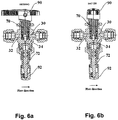
- Figs 6a and 6b presenting another preferred embodiment of the current invention.
- the valve is switchable between METERING and SHUT OFF configurations.
- the stems 70 and 72 are in the positions corresponding to METERING configuration.
- the stem positions are similar to the positions presented in Fig. 5a .
- Fig. 6b presents SHUT OFF configuration where the stem 70 blocks fluid communication of the inlet 32 with the outlets 30 and 34.
- Figs 7a to 7c presenting a further preferred embodiment of the current invention.
- the valve is switchable between METERING, FULL FLOW and SHUT OFF configurations.
- the stems 70 and 72 are in the positions corresponding to METERING configuration.
- the stem positions are similar to the positions presented in Fig. 5a .
- Fig. 7b depicts the FULL FLOW configuration, where the stem 70 provides a straight passage from the inlet 32 to the outlet 30 similar to configuration presented in Fig. 5b .
- the SHUT OFF configuration shown in Fig. 7c is characterized by blocking fluid communication of the inlet 32 with the outlets 30 and 34 by the stem 70 similar to the configuration presented in Fig. 6b .
Landscapes
- Engineering & Computer Science (AREA)
- General Engineering & Computer Science (AREA)
- Mechanical Engineering (AREA)
- Taps Or Cocks (AREA)
- Multiple-Way Valves (AREA)
Description
- The present invention generally relates to valves, and more specifically, to a combination of a ball valve with a needle and/or metering valve.
- Valves suitable for use in instruments and instrumentation systems are well known. One particularly useful type of valve for these systems comprises a ball valve. Generally, a ball valve includes a chamber or body with an internal valve chamber with inlet and outlet passages.
- A ball valve member is disposed within the internal valve chamber. The ball valve member comprises a stainless steel ball positioned centrally within the chamber and a cylindrical valve stem which extends from the ball axially through the chamber to a location outside the body. Packing material surrounds the ball and stem and fills the voids between the ball and the chamber, except for passages which extend from the inlet and outlet passages in the body to the ball. A handle attached to the operating stem allows the ball to be rotated, thereby selectively aligning passages in the ball with the inlet and outlet passages in the body. The ball valve can be a two-way valve with a single inlet and single outlet passage, or a three-way valve with a single inlet and a pair of outlet passages, or a pair of inlet passages and one outlet passage, depending on what the particular application requires.
- A needle valve is a type of valve in which a valve member, or a needle, is mounted within a valve body for axial movement along a valve closure axis into, and out of, a valve seat cavity. Flow passages, opening into the valve seat cavity, are formed in the valve body so that the valve can be closed by inserting the needle into the valve seat cavity and opened by withdrawing the needle from the valve seat cavity while providing more accurate control for the passage of the fluid to the outlet.
- As illustrated in
Fig. 1 , a ball valve 2 and a needle valve 4 can be combined in a parallel manner to control the passage of a fluid withinpipeline 6. These two kinds of valves are usually installed parallel to each other in order to exploit the advantages of each one of the valves for various needs. This solution which is illustrated inFig. 1 suffers from different disadvantages such as: variety of components, many potential leakage points, cost-effectiveness, elevated labor costs, elevated chances for damages, and other disadvantages. -
DE 103 809 C discloses a valve according to the preamble of appended claim 1. -
US 1 921 779 A discloses a gas cock comprising a plug valve and a needle valve connected in a by-pass to it. -
US 2 257 880 A teaches a valve mechanism configured for closing the valve by means of one operation. A rotatable tapered member can be positioned into a closed position by simple rotation thereof. Standard positions corresponding to full flow, shut-off and restricted flow are defined by a control mechanism which is able to discretely fixate the plug in full- flow, shut-off and restricted-flow positions. The control mechanism constitutes an additional arrangement which is appended to a combination of plug and needle valves. The control mechanism comprises a spring-loaded stop washer which is displaced when the valve is switched from one position to another. - Therefore, there is a long felt need to develop a compact valve which will encapsulate both a ball valve and a needle valve in a single construction. The present invention is intended to comply with this requirement.
- The known in the art valve suffer from the following disadvantages:
- 1. Ball valves do not have a regulation mode which is between a fully opened mode and a fully closed mode. The known in the art ball valves are designed to operate only for shut-off control.
- 2. Metering valves are designed to regulate flow in a precise manner, and are not suitable for shut-off control.
- The present invention is directed to a valve as defined by appended claim 1.
- It is another object of the present invention to provide the valve as defined above, wherein the inlet is fluidly connectable to a fluid source.
- It is another object of the present invention to provide the valve as defined above, wherein at least part of the first passage and at least part of the second passage share a common passage.
- It is another object of the present invention to provide the valve as defined above, wherein the first actuating stem is adapted to control the passage of the fluid between the inlet and the first outlet by reconfiguring the ball member from a SHUT OFF POSITION to an FULL FLOW POSITION, and vice versa, in the SHUT OFF POSITION the passage of the fluid between the inlet and the first outlet through the first passage is prevented, and in the FULL FLOW POSITION the passage of the fluid between the inlet and the first outlet through the first passage is available; further wherein the second actuating stem is adapted to control the passage of the fluid between the inlet and the second outlet by reconfiguring the controlling end from a CLOSED METERING POSITION to an OPENED METERING POSITION, and vice versa, in the CLOSED METERING POSITION the passage of the fluid between the inlet and the second outlet through the second passage is prevented, and in the OPENED METERING POSITION the passage of the fluid between the inlet and the second outlet through the second passage is available.
- It is another object of the present invention to provide the valve as defined above, wherein in a combination of the CLOSED METERING POSITION of the second actuating stem, and the FULL FLOW POSITION of the first actuating stem, the fluid is able to pass exclusively between the inlet and the first outlet.
- It is another object of the present invention to provide the valve as defined above, wherein in a combination of the OPENED METERING POSITION of the second actuating stem, and the SHUT OFF POSITION of the first actuating stem, the fluid is able to pass exclusively between the inlet and the second outlet.
- It is another object of the present invention to provide the valve as defined above, wherein in a combination of the OPENED METERING POSITION of the second actuating stem, and the OPENED BALL POSITION of the fist actuating stem, the fluid is able to pass between the inlet and the first outlet, and between the inlet and the second outlet in a combined manner.
- It is another object of the present invention to provide the valve as defined above, wherein the second actuating stem is in an intermediate position between said OPENED METERING POSITION and CLOSED METERING POSITION.
- It is another object of the present invention to provide the valve as defined above, further comprising a first packing bolt threadably connectable to the first bonnet, the first packing bolt is adapted to compress a first packing material locatable between the first packing bolt and the first actuating stem.
- It is another object of the present invention to provide the valve as defined above, wherein the first packing bolt is threadably connectable to the first opening of the first bonnet.
- It is another object of the present invention to provide the valve as defined above, further comprising a second packing nut threadably connectable to the second bonnet, the second packing nut is adapted to compress a second packing material locatable between the second packing nut and the second actuating stem.
- It is another object of the present invention to provide the valve as defined above, wherein the second packing nut is threadably connectable to the outer portion of the second bonnet.
- It is another object of the present invention to provide the valve as defined above, wherein the first actuating stem comprises a first handle adapted to rotate the first actuating stem.
- It is another object of the present invention to provide the valve as defined above, wherein the second actuating stem comprises a second handle adapted to rotate the second actuating stem.
- Further, the present invention is directed to a method of manufacturing a valve as defined by appended claim 15.
- It is another object of the present invention to provide a method of manufacturing a valve as defined above, wherein the first actuating stem is adapted to control the passage of the fluid between the inlet and the first outlet by reconfiguring the ball member from a SHUT OFF POSITION to a FULL FLOW POSITION, and vice versa, in the SHUT OFF POSITION the passage of the fluid between the inlet and the first outlet through the first passage is prevented, and in the FULL FLOW POSITION the passage of the fluid between the inlet and the first outlet through the first passage is available; further wherein the second actuating stem is adapted to control the passage of the fluid between the inlet and the second outlet by reconfiguring the controlling end from a CLOSED METERING POSITION to a OPENED METERING POSITION, and vice versa, in the CLOSED METERING POSITION the passage of the fluid between the inlet and the second outlet through the second passage is prevented, and in the OPENED METERING POSITION the passage of the fluid between the inlet and the second outlet through the second passage is available.
- It is another object of the present invention to provide a method of manufacturing a valve as defined above, wherein the second actuating stem is adapted to provide more accurate control than the first actuating stem for the passage of the fluid from the inlet.
- It is another object of the present invention to provide a method of manufacturing a valve as defined above, further comprising steps of: providing a first packing bolt; compressing a first packing material between the first packing bolt and the first actuating stem; and threadably connecting the first packing bolt to the first bonnet.
- It is another object of the present invention to provide a method of manufacturing a valve as defined above, further comprising steps of: providing a second packing nut; compressing a second packing
material between the second packing nut and the second actuating stem; and threadably connecting the second packing nut to the second bonnet. - It is another object of the present invention to provide a method of manufacturing a valve as defined above, further comprising step of connecting a first handle to the first actuating stem, the first handle is adapted to rotate the first actuating stem.
- It is another object of the present invention to provide a method of manufacturing a valve as defined above, further comprising step of connecting a second handle to the second actuating stem, the second handle is adapted to rotate the second actuating stem.
- For a better understanding of the invention and to show how the same may be carried into effect, reference will now be made, purely by way of example, to the accompanying drawings in which like numerals designate corresponding elements or sections throughout.
- With specific reference now to the drawings in detail, it is stressed that the particulars shown are by way of example and for purposes of illustrative discussion of the preferred embodiments of the present invention only, and are presented in the cause of providing what is believed to be the most useful and readily understood description of the principles and conceptual aspects of the invention. In this regard, no attempt is made to show structural details of the invention in more detail than is necessary for a fundamental understanding of the invention, the description taken with the drawings making apparent to those skilled in the art how the several forms of the invention may be embodied in practice. In the accompanying drawings:
- FIG. 1
- is an illustration of the prior art connection of a ball valve with a needle valve connected in a parallel manner;
- FIG. 2
- is an illustration of a specific embodiment of the present invention;
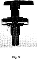
- FIG. 3
- is an illustration of a specific embodiment of the present invention;
- FIGS 4a and 4b
- are illustrations of a prospective views of the specific embodiment of the present invention; and
- FIGS 5a, 5b, 6a, 6b and 7a to 7c
- are cross-sectional views of the present invention functioning as a valve in full flow, metering and shut off states, respectively.
- The drawings together with the description make apparent to those skilled in the art how the invention may be embodied in practice.
- Before explaining at least one embodiment of the invention in detail, it is to be understood that the invention is not limited in its application to the details of construction and the arrangement of the components set forth in the following description or illustrated in the drawings. The invention is applicable to other embodiments or of being practiced or carried out in various ways. Also, it is to be understood that the phraseology and terminology employed herein is for the purpose of description and should not be regarded as limiting.
- The present invention discloses a valve which is a combination of a needle valve and a ball valve. According to some embodiments, the combination of a needle valve and a ball valve in a single construction may be used for implementing the advantages of each one of the valves. For example, the ball valve may be used for instantly opening a passage to a fluid within a pipe, and for instantly closing said passage. On the other hand, the needle valve may be implemented for providing an accurate control of the amount of fluid which may pass within the pipe.
- According to different aspects of the invention, the elements which are implemented in the present invention may be equivalent to any other elements which may be implemented in ball valves and/or needle valves.
- According to the present invention, the present invention has a ball valve with a ball member. The ball member of the present invention is characterized by at least one additional passage extending within the same. This passage is additional to the known in the art passage which is usually used in a ball member of a ball valve.
- The term 'ball member' refers hereinafter to a rounded element which is usually used in a ball valve for controlling and providing the passage of a fluid within the valve.
- The term 'needle valve' refers hereinafter to a valve has a relatively small orifice with a long, tapered seat, and a needle-shaped plunger, on the end of a screw, which exactly fits this seat.
- The term 'metering valve' refers hereinafter to a particular design of a needle valve, that has a thin and sensitive needle. According to different embodiments of the present invention, the terms 'needle valve' and 'metering valve' may refer to the same type of valve. For example, the term "needle valve" may refer the term 'metering valve', and vice versa.
- The present invention is a design of single valve component, which includes both shut-off and sensitive flow regulation, in a single product. In other words, the present invention is a combination of a ball valve with a needle valve (or a metering valve). This combination is able to exploit the advantages of each one of the valve and thereby provide a synergetic effect.
- The present invention is able to provide an excessive flow for a metering valve member due to full flow in the ball valve member, which is not possible in known in the art needle valves (or metering valves) due to limited construction of orifices within the same.
- Reference is now made to
Figs. 2-3 which schematically illustrate a specific embodiment ofvalve 100 of the present invention.Valve 100 may be used for controlling a passage of a fluid within a pipe. According to this embodiment,valve 100, comprises the following components: - a. A
body 10 which comprises: a first bore 12 and a second bore 14 which extend axially inwardly from the exterior ofbody 10 and define avalve chamber 20 therebetween; afirst outlet 30 fluidly connected tovalve chamber 20, and aninlet 32 fluidly connected tovalve chamber 20. - b. A
first bonnet 40 connected to first bore 12 and having afirst opening 42 axially aligned with first bore 12. - c. A
second bonnet 50 connected to second bore 14 and having asecond opening 52 axially aligned with second bore 14. - d. A
ball member 60 disposed withinvalve chamber 20.Ball member 60 comprises afirst passage 62 adapted to allow passage of the fluid betweeninlet 32 andfirst outlet 30. - e. A
first actuating stem 70 connected toball member 60 adapted to be located withinfirst opening 42 offirst bonnet 40 and to control the passage of the fluid betweeninlet 32 andfirst outlet 30. - According to the present invention,
valve 100 further comprises the following components: - f. A
second outlet 34 fluidly connectable tovalve chamber 20 throughsecond opening 52 ofsecond bonnet 50. - g. A
second passage 64 withinball member 60 adapted to provide passage of fluid betweeninlet 32 andsecond outlet 34. - h. A
second actuating stem 72 located withinsecond opening 52 ofsecond bonnet 50 and having a controlling end 74 fitted to be received within second bore, so as to control the passage of the fluid betweeninlet 32 andsecond outlet 34. - According to the specific embodiment of
valve 100 as illustrated inFigs. 2-3 ,inlet 32 is fluidly connectable to a fluid source (not shown). Furthermore, according to this embodiment, first andsecond passages - According to the embodiment of
Figs. 2-3 ,first passage 62 is a horizontal passage which is usually used in known in the art ball valves, andsecond passage 64 is partially vertical and partially horizontal. The horizontal part ofsecond passage 64 and part of first passage 65 form common passage 65. Common passage 65 is adapted to be fluidly connected toinlet 32 whenvalve 100 is actuated (i.e., a fluid passes through the valve). - According to some embodiments,
first actuating stem 70 is adapted to control the passage of the fluid betweeninlet 32 andfirst outlet 30 by reconfiguringball member 60 from a SHUT OFF POSITION to a FULL FLOW POSITION, and vice versa. In the SHUT OFF POSITION, the passage of the fluid betweeninlet 32 andfirst outlet 30 throughfirst passage 62 is prevented, and in the FULL FLOW POSITION, the passage of the fluid betweeninlet 32 andfirst outlet 30 throughfirst passage 62 is available.Second actuating stem 72 is adapted to control the passage of the fluid betweeninlet 32 andsecond outlet 34 by reconfiguring controlling end 74 from a CLOSED METERING POSITION to an OPENED METERING POSITION, and vice versa. In the CLOSED METERING POSITION, the passage of the fluid betweeninlet 32 andsecond outlet 34 throughsecond passage 64 is prevented, and in the OPENED METERING POSITION, the passage of the fluid betweeninlet 32 andsecond outlet 34 throughsecond passage 64 is available. - According to a preferred embodiment of the present invention, the direction of the passage of the fluid is from
inlet 32 tofirst outlet 30 and/orsecond outlet 34. According to other embodiments, the direction of the passage of the fluid is fromfirst outlet 30 and/orsecond outlet 34 toinlet 32. - According to the embodiments of
Figs. 2-3 , the first and the second actuating stems 70 and 72 are adapted to reconfigure the valve, so as the provide or prevent passage of the fluid through the valve, by rotational means. According to a specific embodiment,second actuating stem 72 is threadable withinsecond opening 52 ofsecond bonnet 50. - As illustrated in
Fig. 2 ,second actuating stem 72 is in the OPENED METERING POSITION, andfirst actuating stem 70 is in the SHUT OFF POSITION, such that the fluid is able to pass throughvalve 100 betweeninlet 32 andsecond outlet 34 throughsecond passage 64. In this figure,valve 100 can be used as a known in the art needle/metering valve. - As illustrated in
Fig. 3 ,second actuating stem 72 is in the CLOSED METERING POSITION, andfirst actuating stem 70 is in the FULL FLOW POSITION, such that the fluid is able to pass betweeninlet 32 andfirst outlet 30 throughfirst passage 62. In this figure,valve 100 can be used as a known in the art ball valve. - According to other embodiments, in a combination of a CLOSED METERING POSITION of
second actuating stem 70 with a SHUT OFF POSITION offirst actuating stem 72, the fluid is unable to pass throughvalve 100 frominlet 32 tofirst outlet 30 and tosecond outlet 34, so thevalve 100 is in shut-off position. - According to other embodiments, in a combination of an OPENED METERING POSITION of
second actuating stem 70 with a FULL FLOW POSITION offist actuating stem 72, the fluid is able to pass betweeninlet 32 andfirst outlet 30, and betweeninlet 32 andsecond outlet 34 in a combined manner. - As can be seen in
Figs. 2-3 ,valve 100 further comprises afirst packing bolt 80 threadably connectable to the inner side (to opening 42) offirst bonnet 40. First packingbolt 80 is adapted to compress afirst packing material 85 which is located betweenfirst packing bolt 80 andfirst actuating stem 70. Furthermore,valve 100 comprises asecond packing nut 82 threadably connected to the outside portion ofsecond bonnet 50.Second packing nut 82 is adapted to compress asecond packing material 87 which is located betweensecond packing nut 82 andsecond actuating stem 72. According to the embodiment ofFigs. 2-3 ,first actuating stem 70 comprises afirst handle 90 adapted to rotatefirst actuating stem 70, andsecond actuating stem 72 comprises asecond handle 92 adapted to rotatesecond actuating stem 72. - Reference is now made to
Figs. 4a-b which schematically illustrate perspective view ofvalve 100 of the present invention. InFig. 4a ,second actuating stem 72 is in the OPENED METERING POSITION, andfirst actuating stem 70 is in the SHUT OFF POSITION. InFig. 4b ,second actuating stem 72 is in the CLOSED METERING POSITION, andfirst actuating stem 70 is in the FULL FLOW POSITION. - Reference is now made to
Figs 5a to 5b , presenting one preferred embodiment of the current invention. The valve is switchable between METERING and FULL FLOW configurations. As shown inFig. 5a , the metering configuration is characterized by a position of thestem 70 providing a fluid communication between theinlet 32 and theoutlet 34. A position of thestem 72 controls a rate flow through the valve.Fig. 5b depicts the FULL FLOW configuration, where thestem 70 provides a straight passage from theinlet 32 to theoutlet 30. - Reference is now made to
Figs 6a and 6b , presenting another preferred embodiment of the current invention. The valve is switchable between METERING and SHUT OFF configurations. As shown inFig. 6a , the stems 70 and 72 are in the positions corresponding to METERING configuration. The stem positions are similar to the positions presented inFig. 5a .Fig. 6b presents SHUT OFF configuration where thestem 70 blocks fluid communication of theinlet 32 with theoutlets - Reference is now made to
Figs 7a to 7c , presenting a further preferred embodiment of the current invention. The valve is switchable between METERING, FULL FLOW and SHUT OFF configurations. As shown inFig. 7a , the stems 70 and 72 are in the positions corresponding to METERING configuration. The stem positions are similar to the positions presented inFig. 5a .Fig. 7b depicts the FULL FLOW configuration, where thestem 70 provides a straight passage from theinlet 32 to theoutlet 30 similar to configuration presented inFig. 5b . The SHUT OFF configuration shown inFig. 7c is characterized by blocking fluid communication of theinlet 32 with theoutlets stem 70 similar to the configuration presented inFig. 6b .
Claims (15)
- A valve for controlling a passage of a fluid, comprising:a. a body (10) having: a first bore (12) and a second bore (14) extending inwardly from the exterior of said body (10) and a valve chamber (20) therebetween, a first outlet (30) fluidly connected to said valve chamber (20), and an inlet (32) fluidly connected to said valve chamber (20);b. a first bonnet (40) connected to said first bore (12) and having a first opening (42) axially aligned with said first bore (12);c. a second bonnet (50) connected to said second bore (14) and having a second opening (52) axially aligned with said second bore (14);d. a member (60) disposed within said valve chamber (20), said member (60) comprising a first passage (62) adapted to allow passage of said fluid between said inlet (32) and said first outlet (30); ande. a first actuating stem (70) connected to said member (60), the first actuating stem (70) being located within said first opening (42) of said first bonnet (40) and adapted to control the passage of said fluid between said inlet (32) and said first outlet (30);
said valve further comprising : a second outlet (34) fluidly connectable to said valve chamber (20) through said second opening (52) of said second bonnet (50); a second passage (64) within said member (60) providing passage of said fluid between said inlet (32) and said second outlet (34); and a second actuating stem (72) located within said second opening (52) of said second bonnet (50) and having a controlling end (74) fitted to be received within said second bore (14), so as to control the passage of said fluid between said inlet (32) and said second outlet (34); characterized in that
said member (60) is a ball member (60), and
said first and second bores (12, 14) are axially aligned, and said first and second actuating stems (70, 72) are positioned oppositely in an in-line manner. - The valve according to claim 1, wherein said inlet (32) is fluidly connectable to a fluid source.
- The valve according to claim 1, wherein at least part of said first passage (62) and at least part of said second passage (64) share a common passage.
- The valve according to claim 1, wherein said first actuating stem (70) is adapted to control the passage of said fluid between said inlet (32) and said first outlet (30) by reconfiguring said ball member (60) from a SHUT OFF POSITION to an FULL FLOW POSITION, and vice versa, in said SHUT OFF POSITION said passage of said fluid between said inlet (32) and said first outlet (30) through said first passage (62) is prevented, and in said FULL FLOW POSITION said passage of said fluid between said inlet (32) and said first outlet (30) through said first passage (62) is available; further wherein said second actuating stem (72) is adapted to control the passage of said fluid between said inlet (32) and said second outlet (34) by reconfiguring said controlling end (74) from a CLOSED METERING POSITION to a OPENED METERING POSITION, and vice versa, in said CLOSED METERING POSITION said passage of said fluid between said inlet (32) and said second outlet (34) through said second passage (64) is prevented, and in said OPENED METERING POSITION said passage of said fluid between said inlet (32) and said second outlet (34) through said second passage (64) is available.
- The valve according to claim 4, wherein in a combination of said CLOSED METERING POSITION of said second actuating stem (72), and said FULL FLOW POSITION of said first actuating stem (70), said fluid is able to pass exclusively between said inlet (32) and said first outlet (30).
- The valve according to claim 4, wherein in a combination of said OPENED METERING POSITION of said second actuating stem (72), and said SHUT OFF POSITION of said first actuating stem (70), said fluid is able to pass exclusively between said inlet (32) and said second outlet (34).
- The valve according to claim 4, wherein in a combination of said OPENED METERING POSITION of said second actuating stem (72), and said FULL FLOW POSITION of said first actuating stem (70), said fluid is able to pass between said inlet (32) and said first outlet (30), and between said inlet (32) and said second outlet (34) in a combined manner.
- The valve according to claims 6 or 7, wherein said second actuating stem (72) is in an intermediate position between said OPENED METERING POSITION and CLOSED METERING POSITION.
- The valve according to claim 1, further comprising a first packing bolt (80) threadably connectable to said first bonnet (40), said first packing bolt (80) is adapted to compress a first packing material (85) locatable between said first packing bolt (80) and said first actuating stem (70).
- The valve according to claim 10, wherein said first packing bolt (80) is threadably connectable to said first opening (42) of said first bonnet (40).
- The valve according to claim 1, further comprising a second packing nut (82) threadably connectable to said second bonnet (50), said second packing nut (82) is adapted to compress a second packing material (87) locatable between said second packing nut and said second actuating stem (72).
- The valve according to claim 12, wherein said second packing nut (82) is threadably connectable to said the outer portion of said second bonnet (50).
- The valve according to claim 1, wherein said first actuating stem (70) comprises a first handle (90) adapted to rotate said first actuating stem (70).
- The valve according to claim 1, wherein said second actuating stem (72) comprises a second handle (92) adapted to rotate said second actuating stem (72).
- A method of manufacturing a valve, comprising steps of:a. providing a body (10) having: a first bore (12) and a second bore (14) extending inwardly from the exterior of said body (10) and defining a valve chamber (20) therebetween, a first outlet (30) fluidly connected to said valve chamber (20), and an inlet (32) fluidly connected to said valve chamber (20);b. disposing a member (60) within said valve chamber (20), said member (60) comprising a first passage (62) adapted to allow passage of said fluid between said inlet (32) and said first outlet (30);c. connecting a first bonnet (40) having a first opening (42) to said first bore (12), such that said first opening (42) being axially aligned with said first bore (12);d. connecting a second bonnet (50) having a second opening (52) to said second bore (14), such that said second opening (52) being axially aligned with said second bore (14);e. connecting a first actuating stem (70) to said member (60), said first actuating stem (70) being threaded within said first opening (42) of said first bonnet (40) and controlling the passage of said fluid between said inlet (32) and said first outlet (30);f. providing a second outlet (34) in said body (10), said second outlet (34) being connectable to said valve chamber (20) through said second opening (52) of said second bonnet (50) ;g. providing a second passage (64) within said member (60) adapted to provide passage of said fluid between said inlet (32) and said second outlet (34);h. connecting a second actuating stem (72) to said second bonnet (50) by inserting said second actuating stem (72) into said second opening (52) of said second bonnet (50), said second actuating stem (72) having a controlling end (74) fitted to be received within said second bore (14), so as to control the passage of said fluid between said inlet (32) and said second outlet (34);characterized in that
said member (60) is a ball member (60), and
said first and second bores (12, 14) are axially aligned, and said first and second actuating stems (72, 74) are positioned oppositely in an in-line manner.
Applications Claiming Priority (2)
| Application Number | Priority Date | Filing Date | Title |
|---|---|---|---|
| US37668210P | 2010-08-25 | 2010-08-25 | |
| PCT/IL2011/000688 WO2012025929A1 (en) | 2010-08-25 | 2011-08-25 | A metering ball valve |
Publications (2)
| Publication Number | Publication Date |
|---|---|
| EP2609350A1 EP2609350A1 (en) | 2013-07-03 |
| EP2609350B1 true EP2609350B1 (en) | 2017-10-04 |
Family
ID=44786041
Family Applications (1)
| Application Number | Title | Priority Date | Filing Date |
|---|---|---|---|
| EP11767774.0A Active EP2609350B1 (en) | 2010-08-25 | 2011-08-25 | A metering ball valve |
Country Status (5)
| Country | Link |
|---|---|
| US (1) | US8590569B2 (en) |
| EP (1) | EP2609350B1 (en) |
| JP (1) | JP5911490B2 (en) |
| KR (1) | KR101890402B1 (en) |
| WO (1) | WO2012025929A1 (en) |
Families Citing this family (1)
| Publication number | Priority date | Publication date | Assignee | Title |
|---|---|---|---|---|
| WO2014130757A1 (en) * | 2013-02-23 | 2014-08-28 | Aspire Bariatrics, Inc. | Apparatus and method for draining material from a stomach |
Family Cites Families (13)
| Publication number | Priority date | Publication date | Assignee | Title |
|---|---|---|---|---|
| DE103809C (en) * | ||||
| USRE18430E (en) * | 1932-04-19 | of detroit | ||
| US1921779A (en) * | 1932-03-21 | 1933-08-08 | Roberts Brass Mfg Company | Gas cock |
| US2013822A (en) * | 1933-05-05 | 1935-09-10 | Florence Stove Co | Burner control device |
| US1973418A (en) * | 1933-12-18 | 1934-09-11 | Andrew J Morse & Son Inc | Shut off valve |
| GB508337A (en) * | 1938-07-18 | 1939-06-29 | William Henry Abrahams Dandrid | Improvements in rotary plug valves with spherical plugs |
| US2257880A (en) * | 1940-03-04 | 1941-10-07 | Harper Wyman Co | Valve mechanism and the like |
| US2987078A (en) * | 1957-12-16 | 1961-06-06 | Lincoln Brass Works | Gas valve |
| US2959187A (en) * | 1958-08-18 | 1960-11-08 | Otis Eng Co | Ball-type surface safety valve |
| FR2606853B1 (en) * | 1986-11-14 | 1989-03-03 | Gaz De France | PERFECTED SAS VALVE |
| JPH0223982Y2 (en) * | 1989-01-12 | 1990-06-29 | ||
| GB8924470D0 (en) * | 1989-10-31 | 1989-12-20 | Havlik Technologies Inc | High performance valve |
| GB0508337D0 (en) | 2005-04-26 | 2005-06-01 | Edwards Jacqueline | Fragranced disposable toilet seat cover |
-
2011
- 2011-08-25 JP JP2013525421A patent/JP5911490B2/en active Active
- 2011-08-25 US US13/818,430 patent/US8590569B2/en active Active
- 2011-08-25 EP EP11767774.0A patent/EP2609350B1/en active Active
- 2011-08-25 WO PCT/IL2011/000688 patent/WO2012025929A1/en not_active Ceased
- 2011-08-25 KR KR1020137006129A patent/KR101890402B1/en active Active
Non-Patent Citations (1)
| Title |
|---|
| None * |
Also Published As
| Publication number | Publication date |
|---|---|
| JP2013536386A (en) | 2013-09-19 |
| WO2012025929A1 (en) | 2012-03-01 |
| EP2609350A1 (en) | 2013-07-03 |
| KR20130094820A (en) | 2013-08-26 |
| KR101890402B1 (en) | 2018-08-21 |
| US20130187074A1 (en) | 2013-07-25 |
| US8590569B2 (en) | 2013-11-26 |
| JP5911490B2 (en) | 2016-04-27 |
Similar Documents
| Publication | Publication Date | Title |
|---|---|---|
| US11592115B2 (en) | Fluid valve | |
| US20190353253A1 (en) | Isolation valve assembly | |
| US8740186B2 (en) | Valve and a method for providing such a valve | |
| CN101523097A (en) | Flow adjustment valve | |
| EP3315838A1 (en) | Top cover for a soft throttling valve body, soft throttling valve and method for assembling a soft throttling valve | |
| RU2477404C2 (en) | Throttling device of effective cross-section of steam line or its similar facilities | |
| EP0884539B1 (en) | Connector assembly for connecting an expansion vessel for hot sanitary water | |
| EP1649201B1 (en) | Multiport valve | |
| US8590569B2 (en) | Metering ball valve | |
| WO2017039823A1 (en) | Needle valve and associated methods | |
| WO1999031416A1 (en) | In-line valve | |
| RU2485377C2 (en) | Compact flap valve | |
| EP2085670A1 (en) | By-pass valve | |
| CA2619400A1 (en) | Packing nut for control valve | |
| EP2672153B1 (en) | Ball valve | |
| RU2357141C1 (en) | Double-circuit cock | |
| US20190338861A1 (en) | Valve arrangement | |
| CN201858391U (en) | Internal threaded ball valve | |
| DE10211533B4 (en) | Hahn block | |
| US20200191298A1 (en) | Flow Control Valve | |
| EP1460354A1 (en) | Security group for a water heater | |
| US2595856A (en) | Faucet | |
| CN105444244B (en) | Water distributing and collecting device | |
| US8267117B2 (en) | Fuel shutoff valve | |
| RU183745U1 (en) | CRANE |
Legal Events
| Date | Code | Title | Description |
|---|---|---|---|
| PUAI | Public reference made under article 153(3) epc to a published international application that has entered the european phase |
Free format text: ORIGINAL CODE: 0009012 |
|
| 17P | Request for examination filed |
Effective date: 20130307 |
|
| AK | Designated contracting states |
Kind code of ref document: A1 Designated state(s): AL AT BE BG CH CY CZ DE DK EE ES FI FR GB GR HR HU IE IS IT LI LT LU LV MC MK MT NL NO PL PT RO RS SE SI SK SM TR |
|
| DAX | Request for extension of the european patent (deleted) | ||
| 17Q | First examination report despatched |
Effective date: 20140113 |
|
| GRAP | Despatch of communication of intention to grant a patent |
Free format text: ORIGINAL CODE: EPIDOSNIGR1 |
|
| STAA | Information on the status of an ep patent application or granted ep patent |
Free format text: STATUS: GRANT OF PATENT IS INTENDED |
|
| INTG | Intention to grant announced |
Effective date: 20170404 |
|
| GRAS | Grant fee paid |
Free format text: ORIGINAL CODE: EPIDOSNIGR3 |
|
| GRAA | (expected) grant |
Free format text: ORIGINAL CODE: 0009210 |
|
| STAA | Information on the status of an ep patent application or granted ep patent |
Free format text: STATUS: THE PATENT HAS BEEN GRANTED |
|
| AK | Designated contracting states |
Kind code of ref document: B1 Designated state(s): AL AT BE BG CH CY CZ DE DK EE ES FI FR GB GR HR HU IE IS IT LI LT LU LV MC MK MT NL NO PL PT RO RS SE SI SK SM TR |
|
| REG | Reference to a national code |
Ref country code: GB Ref legal event code: FG4D |
|
| REG | Reference to a national code |
Ref country code: CH Ref legal event code: EP |
|
| REG | Reference to a national code |
Ref country code: AT Ref legal event code: REF Ref document number: 934371 Country of ref document: AT Kind code of ref document: T Effective date: 20171015 |
|
| REG | Reference to a national code |
Ref country code: IE Ref legal event code: FG4D |
|
| REG | Reference to a national code |
Ref country code: DE Ref legal event code: R096 Ref document number: 602011042125 Country of ref document: DE |
|
| REG | Reference to a national code |
Ref country code: NL Ref legal event code: MP Effective date: 20171004 |
|
| REG | Reference to a national code |
Ref country code: LT Ref legal event code: MG4D |
|
| REG | Reference to a national code |
Ref country code: AT Ref legal event code: MK05 Ref document number: 934371 Country of ref document: AT Kind code of ref document: T Effective date: 20171004 |
|
| PG25 | Lapsed in a contracting state [announced via postgrant information from national office to epo] |
Ref country code: NL Free format text: LAPSE BECAUSE OF FAILURE TO SUBMIT A TRANSLATION OF THE DESCRIPTION OR TO PAY THE FEE WITHIN THE PRESCRIBED TIME-LIMIT Effective date: 20171004 |
|
| PG25 | Lapsed in a contracting state [announced via postgrant information from national office to epo] |
Ref country code: FI Free format text: LAPSE BECAUSE OF FAILURE TO SUBMIT A TRANSLATION OF THE DESCRIPTION OR TO PAY THE FEE WITHIN THE PRESCRIBED TIME-LIMIT Effective date: 20171004 Ref country code: NO Free format text: LAPSE BECAUSE OF FAILURE TO SUBMIT A TRANSLATION OF THE DESCRIPTION OR TO PAY THE FEE WITHIN THE PRESCRIBED TIME-LIMIT Effective date: 20180104 Ref country code: SE Free format text: LAPSE BECAUSE OF FAILURE TO SUBMIT A TRANSLATION OF THE DESCRIPTION OR TO PAY THE FEE WITHIN THE PRESCRIBED TIME-LIMIT Effective date: 20171004 Ref country code: LT Free format text: LAPSE BECAUSE OF FAILURE TO SUBMIT A TRANSLATION OF THE DESCRIPTION OR TO PAY THE FEE WITHIN THE PRESCRIBED TIME-LIMIT Effective date: 20171004 Ref country code: ES Free format text: LAPSE BECAUSE OF FAILURE TO SUBMIT A TRANSLATION OF THE DESCRIPTION OR TO PAY THE FEE WITHIN THE PRESCRIBED TIME-LIMIT Effective date: 20171004 |
|
| PG25 | Lapsed in a contracting state [announced via postgrant information from national office to epo] |
Ref country code: GR Free format text: LAPSE BECAUSE OF FAILURE TO SUBMIT A TRANSLATION OF THE DESCRIPTION OR TO PAY THE FEE WITHIN THE PRESCRIBED TIME-LIMIT Effective date: 20180105 Ref country code: BG Free format text: LAPSE BECAUSE OF FAILURE TO SUBMIT A TRANSLATION OF THE DESCRIPTION OR TO PAY THE FEE WITHIN THE PRESCRIBED TIME-LIMIT Effective date: 20180104 Ref country code: LV Free format text: LAPSE BECAUSE OF FAILURE TO SUBMIT A TRANSLATION OF THE DESCRIPTION OR TO PAY THE FEE WITHIN THE PRESCRIBED TIME-LIMIT Effective date: 20171004 Ref country code: AT Free format text: LAPSE BECAUSE OF FAILURE TO SUBMIT A TRANSLATION OF THE DESCRIPTION OR TO PAY THE FEE WITHIN THE PRESCRIBED TIME-LIMIT Effective date: 20171004 Ref country code: RS Free format text: LAPSE BECAUSE OF FAILURE TO SUBMIT A TRANSLATION OF THE DESCRIPTION OR TO PAY THE FEE WITHIN THE PRESCRIBED TIME-LIMIT Effective date: 20171004 Ref country code: IS Free format text: LAPSE BECAUSE OF FAILURE TO SUBMIT A TRANSLATION OF THE DESCRIPTION OR TO PAY THE FEE WITHIN THE PRESCRIBED TIME-LIMIT Effective date: 20180204 Ref country code: HR Free format text: LAPSE BECAUSE OF FAILURE TO SUBMIT A TRANSLATION OF THE DESCRIPTION OR TO PAY THE FEE WITHIN THE PRESCRIBED TIME-LIMIT Effective date: 20171004 |
|
| REG | Reference to a national code |
Ref country code: DE Ref legal event code: R097 Ref document number: 602011042125 Country of ref document: DE |
|
| PG25 | Lapsed in a contracting state [announced via postgrant information from national office to epo] |
Ref country code: CZ Free format text: LAPSE BECAUSE OF FAILURE TO SUBMIT A TRANSLATION OF THE DESCRIPTION OR TO PAY THE FEE WITHIN THE PRESCRIBED TIME-LIMIT Effective date: 20171004 Ref country code: EE Free format text: LAPSE BECAUSE OF FAILURE TO SUBMIT A TRANSLATION OF THE DESCRIPTION OR TO PAY THE FEE WITHIN THE PRESCRIBED TIME-LIMIT Effective date: 20171004 Ref country code: DK Free format text: LAPSE BECAUSE OF FAILURE TO SUBMIT A TRANSLATION OF THE DESCRIPTION OR TO PAY THE FEE WITHIN THE PRESCRIBED TIME-LIMIT Effective date: 20171004 Ref country code: SK Free format text: LAPSE BECAUSE OF FAILURE TO SUBMIT A TRANSLATION OF THE DESCRIPTION OR TO PAY THE FEE WITHIN THE PRESCRIBED TIME-LIMIT Effective date: 20171004 |
|
| PLBE | No opposition filed within time limit |
Free format text: ORIGINAL CODE: 0009261 |
|
| STAA | Information on the status of an ep patent application or granted ep patent |
Free format text: STATUS: NO OPPOSITION FILED WITHIN TIME LIMIT |
|
| PG25 | Lapsed in a contracting state [announced via postgrant information from national office to epo] |
Ref country code: RO Free format text: LAPSE BECAUSE OF FAILURE TO SUBMIT A TRANSLATION OF THE DESCRIPTION OR TO PAY THE FEE WITHIN THE PRESCRIBED TIME-LIMIT Effective date: 20171004 Ref country code: PL Free format text: LAPSE BECAUSE OF FAILURE TO SUBMIT A TRANSLATION OF THE DESCRIPTION OR TO PAY THE FEE WITHIN THE PRESCRIBED TIME-LIMIT Effective date: 20171004 Ref country code: SM Free format text: LAPSE BECAUSE OF FAILURE TO SUBMIT A TRANSLATION OF THE DESCRIPTION OR TO PAY THE FEE WITHIN THE PRESCRIBED TIME-LIMIT Effective date: 20171004 Ref country code: IT Free format text: LAPSE BECAUSE OF FAILURE TO SUBMIT A TRANSLATION OF THE DESCRIPTION OR TO PAY THE FEE WITHIN THE PRESCRIBED TIME-LIMIT Effective date: 20171004 |
|
| 26N | No opposition filed |
Effective date: 20180705 |
|
| PG25 | Lapsed in a contracting state [announced via postgrant information from national office to epo] |
Ref country code: SI Free format text: LAPSE BECAUSE OF FAILURE TO SUBMIT A TRANSLATION OF THE DESCRIPTION OR TO PAY THE FEE WITHIN THE PRESCRIBED TIME-LIMIT Effective date: 20171004 |
|
| PG25 | Lapsed in a contracting state [announced via postgrant information from national office to epo] |
Ref country code: MC Free format text: LAPSE BECAUSE OF FAILURE TO SUBMIT A TRANSLATION OF THE DESCRIPTION OR TO PAY THE FEE WITHIN THE PRESCRIBED TIME-LIMIT Effective date: 20171004 |
|
| REG | Reference to a national code |
Ref country code: CH Ref legal event code: PL |
|
| GBPC | Gb: european patent ceased through non-payment of renewal fee |
Effective date: 20180825 |
|
| PG25 | Lapsed in a contracting state [announced via postgrant information from national office to epo] |
Ref country code: CH Free format text: LAPSE BECAUSE OF NON-PAYMENT OF DUE FEES Effective date: 20180831 Ref country code: LI Free format text: LAPSE BECAUSE OF NON-PAYMENT OF DUE FEES Effective date: 20180831 Ref country code: LU Free format text: LAPSE BECAUSE OF NON-PAYMENT OF DUE FEES Effective date: 20180825 |
|
| REG | Reference to a national code |
Ref country code: BE Ref legal event code: MM Effective date: 20180831 |
|
| PG25 | Lapsed in a contracting state [announced via postgrant information from national office to epo] |
Ref country code: FR Free format text: LAPSE BECAUSE OF NON-PAYMENT OF DUE FEES Effective date: 20180831 Ref country code: BE Free format text: LAPSE BECAUSE OF NON-PAYMENT OF DUE FEES Effective date: 20180831 |
|
| PG25 | Lapsed in a contracting state [announced via postgrant information from national office to epo] |
Ref country code: GB Free format text: LAPSE BECAUSE OF NON-PAYMENT OF DUE FEES Effective date: 20180825 |
|
| PG25 | Lapsed in a contracting state [announced via postgrant information from national office to epo] |
Ref country code: MT Free format text: LAPSE BECAUSE OF NON-PAYMENT OF DUE FEES Effective date: 20180825 |
|
| PG25 | Lapsed in a contracting state [announced via postgrant information from national office to epo] |
Ref country code: TR Free format text: LAPSE BECAUSE OF FAILURE TO SUBMIT A TRANSLATION OF THE DESCRIPTION OR TO PAY THE FEE WITHIN THE PRESCRIBED TIME-LIMIT Effective date: 20171004 |
|
| PG25 | Lapsed in a contracting state [announced via postgrant information from national office to epo] |
Ref country code: PT Free format text: LAPSE BECAUSE OF FAILURE TO SUBMIT A TRANSLATION OF THE DESCRIPTION OR TO PAY THE FEE WITHIN THE PRESCRIBED TIME-LIMIT Effective date: 20171004 Ref country code: HU Free format text: LAPSE BECAUSE OF FAILURE TO SUBMIT A TRANSLATION OF THE DESCRIPTION OR TO PAY THE FEE WITHIN THE PRESCRIBED TIME-LIMIT; INVALID AB INITIO Effective date: 20110825 |
|
| PG25 | Lapsed in a contracting state [announced via postgrant information from national office to epo] |
Ref country code: CY Free format text: LAPSE BECAUSE OF FAILURE TO SUBMIT A TRANSLATION OF THE DESCRIPTION OR TO PAY THE FEE WITHIN THE PRESCRIBED TIME-LIMIT Effective date: 20171004 Ref country code: IE Free format text: LAPSE BECAUSE OF NON-PAYMENT OF DUE FEES Effective date: 20180825 Ref country code: MK Free format text: LAPSE BECAUSE OF NON-PAYMENT OF DUE FEES Effective date: 20171004 |
|
| PG25 | Lapsed in a contracting state [announced via postgrant information from national office to epo] |
Ref country code: AL Free format text: LAPSE BECAUSE OF FAILURE TO SUBMIT A TRANSLATION OF THE DESCRIPTION OR TO PAY THE FEE WITHIN THE PRESCRIBED TIME-LIMIT Effective date: 20171004 |
|
| PGFP | Annual fee paid to national office [announced via postgrant information from national office to epo] |
Ref country code: DE Payment date: 20250829 Year of fee payment: 15 |