EP2608705B1 - Controlled motorized brewing unit - Google Patents
Controlled motorized brewing unit Download PDFInfo
- Publication number
- EP2608705B1 EP2608705B1 EP11719510.7A EP11719510A EP2608705B1 EP 2608705 B1 EP2608705 B1 EP 2608705B1 EP 11719510 A EP11719510 A EP 11719510A EP 2608705 B1 EP2608705 B1 EP 2608705B1
- Authority
- EP
- European Patent Office
- Prior art keywords
- capsule
- machine
- motor
- assemblies
- assembly
- Prior art date
- Legal status (The legal status is an assumption and is not a legal conclusion. Google has not performed a legal analysis and makes no representation as to the accuracy of the status listed.)
- Active
Links
- 239000002775 capsule Substances 0.000 claims description 84
- 230000000712 assembly Effects 0.000 claims description 55
- 238000000429 assembly Methods 0.000 claims description 55
- 235000013361 beverage Nutrition 0.000 claims description 43
- XLYOFNOQVPJJNP-UHFFFAOYSA-N water Substances O XLYOFNOQVPJJNP-UHFFFAOYSA-N 0.000 claims description 37
- 239000004615 ingredient Substances 0.000 claims description 32
- 230000002159 abnormal effect Effects 0.000 claims description 19
- 230000005540 biological transmission Effects 0.000 claims description 17
- 240000007154 Coffea arabica Species 0.000 claims description 16
- 235000016213 coffee Nutrition 0.000 claims description 16
- 235000013353 coffee beverage Nutrition 0.000 claims description 16
- 230000033001 locomotion Effects 0.000 claims description 13
- 230000009471 action Effects 0.000 claims description 10
- 238000010521 absorption reaction Methods 0.000 claims description 9
- 230000004913 activation Effects 0.000 claims description 8
- 244000299461 Theobroma cacao Species 0.000 claims description 7
- 238000002347 injection Methods 0.000 claims description 7
- 239000007924 injection Substances 0.000 claims description 7
- 235000013616 tea Nutrition 0.000 claims description 6
- 244000269722 Thea sinensis Species 0.000 claims description 5
- 239000008267 milk Substances 0.000 claims description 5
- 235000013336 milk Nutrition 0.000 claims description 5
- 210000004080 milk Anatomy 0.000 claims description 5
- 235000019219 chocolate Nutrition 0.000 claims description 4
- 235000005764 Theobroma cacao ssp. cacao Nutrition 0.000 claims description 3
- 235000005767 Theobroma cacao ssp. sphaerocarpum Nutrition 0.000 claims description 3
- 238000013459 approach Methods 0.000 claims description 3
- 235000001046 cacaotero Nutrition 0.000 claims description 3
- 235000014347 soups Nutrition 0.000 claims description 3
- 235000008452 baby food Nutrition 0.000 claims description 2
- 230000000750 progressive effect Effects 0.000 claims description 2
- 238000012546 transfer Methods 0.000 claims description 2
- 238000000034 method Methods 0.000 claims 2
- 230000006870 function Effects 0.000 description 12
- 238000002360 preparation method Methods 0.000 description 9
- 230000001960 triggered effect Effects 0.000 description 6
- 238000001802 infusion Methods 0.000 description 5
- 238000003780 insertion Methods 0.000 description 5
- 230000037431 insertion Effects 0.000 description 5
- 230000000875 corresponding effect Effects 0.000 description 4
- 238000010438 heat treatment Methods 0.000 description 4
- 239000007788 liquid Substances 0.000 description 4
- 238000004519 manufacturing process Methods 0.000 description 3
- 230000007246 mechanism Effects 0.000 description 3
- 238000004806 packaging method and process Methods 0.000 description 3
- 230000036961 partial effect Effects 0.000 description 3
- 230000002829 reductive effect Effects 0.000 description 3
- RVCKCEDKBVEEHL-UHFFFAOYSA-N 2,3,4,5,6-pentachlorobenzyl alcohol Chemical compound OCC1=C(Cl)C(Cl)=C(Cl)C(Cl)=C1Cl RVCKCEDKBVEEHL-UHFFFAOYSA-N 0.000 description 2
- 208000027418 Wounds and injury Diseases 0.000 description 2
- 230000008901 benefit Effects 0.000 description 2
- 235000020291 caffè lungo Nutrition 0.000 description 2
- 230000001276 controlling effect Effects 0.000 description 2
- 230000000694 effects Effects 0.000 description 2
- 235000015114 espresso Nutrition 0.000 description 2
- 238000011049 filling Methods 0.000 description 2
- 208000014674 injury Diseases 0.000 description 2
- 238000012544 monitoring process Methods 0.000 description 2
- 239000000843 powder Substances 0.000 description 2
- 239000000243 solution Substances 0.000 description 2
- 230000003068 static effect Effects 0.000 description 2
- XAGFODPZIPBFFR-UHFFFAOYSA-N aluminium Chemical compound [Al] XAGFODPZIPBFFR-UHFFFAOYSA-N 0.000 description 1
- 229910052782 aluminium Inorganic materials 0.000 description 1
- 239000004411 aluminium Substances 0.000 description 1
- 230000006399 behavior Effects 0.000 description 1
- 235000015109 caffè americano Nutrition 0.000 description 1
- 235000015115 caffè latte Nutrition 0.000 description 1
- 235000015116 cappuccino Nutrition 0.000 description 1
- 238000004140 cleaning Methods 0.000 description 1
- 238000010276 construction Methods 0.000 description 1
- 230000002596 correlated effect Effects 0.000 description 1
- 230000006378 damage Effects 0.000 description 1
- 230000001419 dependent effect Effects 0.000 description 1
- 238000007599 discharging Methods 0.000 description 1
- 238000009826 distribution Methods 0.000 description 1
- 238000000605 extraction Methods 0.000 description 1
- 239000012530 fluid Substances 0.000 description 1
- 239000011521 glass Substances 0.000 description 1
- 230000002401 inhibitory effect Effects 0.000 description 1
- 238000011068 loading method Methods 0.000 description 1
- 230000007257 malfunction Effects 0.000 description 1
- 239000000463 material Substances 0.000 description 1
- 230000015654 memory Effects 0.000 description 1
- 238000002156 mixing Methods 0.000 description 1
- 238000012545 processing Methods 0.000 description 1
- 235000020288 ristretto Nutrition 0.000 description 1
- 239000000126 substance Substances 0.000 description 1
Images


Classifications
-
- A—HUMAN NECESSITIES
- A47—FURNITURE; DOMESTIC ARTICLES OR APPLIANCES; COFFEE MILLS; SPICE MILLS; SUCTION CLEANERS IN GENERAL
- A47J—KITCHEN EQUIPMENT; COFFEE MILLS; SPICE MILLS; APPARATUS FOR MAKING BEVERAGES
- A47J31/00—Apparatus for making beverages
- A47J31/24—Coffee-making apparatus in which hot water is passed through the filter under pressure, i.e. in which the coffee grounds are extracted under pressure
- A47J31/34—Coffee-making apparatus in which hot water is passed through the filter under pressure, i.e. in which the coffee grounds are extracted under pressure with hot water under liquid pressure
- A47J31/36—Coffee-making apparatus in which hot water is passed through the filter under pressure, i.e. in which the coffee grounds are extracted under pressure with hot water under liquid pressure with mechanical pressure-producing means
-
- A—HUMAN NECESSITIES
- A47—FURNITURE; DOMESTIC ARTICLES OR APPLIANCES; COFFEE MILLS; SPICE MILLS; SUCTION CLEANERS IN GENERAL
- A47J—KITCHEN EQUIPMENT; COFFEE MILLS; SPICE MILLS; APPARATUS FOR MAKING BEVERAGES
- A47J31/00—Apparatus for making beverages
- A47J31/44—Parts or details or accessories of beverage-making apparatus
- A47J31/4403—Constructional details
- A47J31/446—Filter holding means; Attachment of filters to beverage-making apparatus
-
- A—HUMAN NECESSITIES
- A47—FURNITURE; DOMESTIC ARTICLES OR APPLIANCES; COFFEE MILLS; SPICE MILLS; SUCTION CLEANERS IN GENERAL
- A47J—KITCHEN EQUIPMENT; COFFEE MILLS; SPICE MILLS; APPARATUS FOR MAKING BEVERAGES
- A47J31/00—Apparatus for making beverages
- A47J31/24—Coffee-making apparatus in which hot water is passed through the filter under pressure, i.e. in which the coffee grounds are extracted under pressure
- A47J31/34—Coffee-making apparatus in which hot water is passed through the filter under pressure, i.e. in which the coffee grounds are extracted under pressure with hot water under liquid pressure
- A47J31/36—Coffee-making apparatus in which hot water is passed through the filter under pressure, i.e. in which the coffee grounds are extracted under pressure with hot water under liquid pressure with mechanical pressure-producing means
- A47J31/3604—Coffee-making apparatus in which hot water is passed through the filter under pressure, i.e. in which the coffee grounds are extracted under pressure with hot water under liquid pressure with mechanical pressure-producing means with a mechanism arranged to move the brewing chamber between loading, infusing and ejecting stations
- A47J31/3623—Cartridges being employed
- A47J31/3633—Means to perform transfer from a loading position to an infusing position
-
- A—HUMAN NECESSITIES
- A47—FURNITURE; DOMESTIC ARTICLES OR APPLIANCES; COFFEE MILLS; SPICE MILLS; SUCTION CLEANERS IN GENERAL
- A47J—KITCHEN EQUIPMENT; COFFEE MILLS; SPICE MILLS; APPARATUS FOR MAKING BEVERAGES
- A47J31/00—Apparatus for making beverages
- A47J31/40—Beverage-making apparatus with dispensing means for adding a measured quantity of ingredients, e.g. coffee, water, sugar, cocoa, milk, tea
- A47J31/407—Beverage-making apparatus with dispensing means for adding a measured quantity of ingredients, e.g. coffee, water, sugar, cocoa, milk, tea with ingredient-containing cartridges; Cartridge-perforating means
-
- A—HUMAN NECESSITIES
- A47—FURNITURE; DOMESTIC ARTICLES OR APPLIANCES; COFFEE MILLS; SPICE MILLS; SUCTION CLEANERS IN GENERAL
- A47J—KITCHEN EQUIPMENT; COFFEE MILLS; SPICE MILLS; APPARATUS FOR MAKING BEVERAGES
- A47J31/00—Apparatus for making beverages
- A47J31/44—Parts or details or accessories of beverage-making apparatus
- A47J31/58—Safety devices
Definitions
- the present invention relates to a beverage machine for the preparation of a beverage from an ingredient capsule. More particularly, the machine has a motorized brewing unit and a control for closing the brewing unit in a convenient and safe manner.
- the brewing unit comprises in particular: first and second assemblies each delimiting a part of a brewing chamber; and an ingredient capsule between the assemblies.
- the invention also concerns a use of an ingredient capsule for implementing such a beverage machine with a capsule.
- a "beverage” is meant to include any human-consumable liquid substance, such as tea, coffee, hot or cold chocolate, milk, soup, baby food, etc.
- a "capsule” is meant to include any pre-portioned beverage ingredient, such as a flavouring ingredient, within an enclosing packaging of any material, in particular an airtight packaging, e.g. plastic, aluminium, recyclable and/or biodegradable packagings, and of any shape and structure, including soft pods or rigid cartridges containing the ingredient.
- Certain beverage preparation machines use capsules containing ingredients to be extracted or to be dissolved and/or ingredients that are stored and dosed automatically in the machine or else are added at the time of preparation of the drink.
- Some beverage machines possess filling means that include a pump for liquid, usually water, which pumps the liquid from a source of water that is cold or indeed heated through heating means, e.g. a thermoblock or the like.
- a capsule containing beverage ingredients is inserted in a brewing device.
- the brewing device is tightly closed about the capsule, water is injected at the first face of the capsule, the beverage is produced in the closed volume of the capsule and a brewed beverage can be drained from a second face of the capsule and collected into a receptacle such as a cup or glass.
- Brewing devices have been developed to facilitate insertion of a "fresh" capsule and removal of the capsule upon use.
- WO 2005/004683 and WO 2007/135136 relate to such brewing devices.
- the devices comprise a frame, a fixed holding part for the capsule, a movable holding part which is mounted relative to the frame in a sliding relationship, one or two knuckle joint mechanisms that provide a mechanical system which enables to close in a steady and fluid-tight manner the holding parts about the capsule while also resisting to the counter-force acting while re-opening and generated by the internal brewing pressure, and a handle for directly levering the knuckle joint mechanism.
- Such a device forms a simple assembly enabling insertion of the capsule by vertical fall through a passage in the frame and removal of the used capsule in the same direction as the insertion direction.
- the handle may serve to cover and uncover the passage for the capsule.
- the movable parts of the brewing device are actuated manually via the handle.
- the manual force required to move the movable parts varies during closure and opening of the machine and depends on the dimensional tolerances of the capsules used and the positioning and nature of the capsules as well as the temperature of the brewing unit.
- WO 2009/043630 discloses a beverage preparation machine including a brewing unit having a front part with a passage for inserting a capsule into the brewing unit.
- the front part is arranged to telescope out of the machine's housing for uncovering the passage for inserting a capsule into the brewing unit and telescopes into the brewing unit for sliding the passage under the housing and thus covering the passage by the housing.
- the actuation of the movable part of the brewing device may be motorized.
- EP 1 767 129 relates to a motor-driven extraction module for a capsule-based beverage production device.
- the brewing device has a capsule insertion passage provided with a safety door assembled to the movable part of the brewing device via a switch for detecting an undesired presence of a finger in the passage during closure and prevent squeezing-injuries by stopping the motor before any finger is caught in the brewing device.
- An object of the invention is to provide a motorized closure function of the brewing unit for providing more convenience in loading and ejection of the ingredient capsule and reducing user's intervention. Another object is to provide a safe operation by reducing the risk of injuries while using a motorized beverage machine. Another object is to provide added value functionalities such as semi-automatic or automatic brewing, rinsing and/or de-scaling modes. Another object is to control optimal conditions for rinsing and/or de-scaling the machine.
- the invention relates to a motorized machine for preparing and dispensing a beverage and more particularly to a beverage machine having a motorized brewing unit.
- the machine is a coffee, tea, chocolate, cacao, milk or soup preparation machine.
- the machine is arranged for preparing within a beverage processing module a beverage by passing hot or cold water or another liquid through a capsule containing an ingredient, such as a flavouring ingredient, of the beverage to be prepared, such as ground coffee or tea or chocolate or cacao or milk powder.
- Such beverage preparation typically includes the mixing of a plurality of beverage ingredients, e.g. water and milk powder, and/or the infusion of a beverage ingredient, such as an infusion of ground coffee or tea with water.
- a predetermined amount of beverage is formed and dispensed on user-request, which corresponds to a serving.
- the volume of such a serving may be in the range of 25 to 200 ml, e.g. the volume for filling a cup or mug, depending on the type of beverage.
- Formed and dispensed beverages may be selected from ristrettos, espressos, lungos, cappuccinos, café latte, americano coffees, teas, etc...
- a coffee machine may be configured for dispensing espressos, e.g. an adjustable volume of 20 to 60 ml per serving, and/or for dispensing lungos, e.g. a volume in the range of 70 to 150 ml per serving.
- the motorized beverage machine has a brewing unit that comprises a first assembly and a second assembly cooperating together, each assembly delimiting part of a brewing chamber for containing an ingredient capsule. At least one of these assemblies is:
- the assemblies are relatively movable to one another.
- One assembly may be fixed in the machine, e.g. in the main frame or outer housing of the machine, and the other assembly may be movable thereto.
- both assemblies may be movable in the machine, e.g. in the main frame or outer housing of the machine.
- the machine comprises activation means that include:
- the motorized beverage machine comprises means for measuring at least one electrical parameter representative of the motor power consumption and for comparing the evolution of this measured parameter as a function of time during the transfer of the assembly from the open to the closed position to a set reference and means for providing an input to at least one of said activation means as a result of the compared evolution of said measured parameter.
- the circumstances under which the assemblies are moved to the open and/or closed position can be monitored by monitoring the power consumption of the motor.
- the required mechanical output energy of the motor to produce a movement is directly linked to its consumed input energy, e.g. electric energy, can be measured.
- the set reference may be based on a power consumption modelisation and/or an empiric power consumption measure under predetermined conditions, e.g. with or without ingredient capsule in the brewing unit, specific environment of use, etc...
- the set reference typically includes a tolerance margin to take into account variations that may occur e.g. due to the environment of use and/or manufacturing tolerances and/or handling tolerances.
- the motor is controlled to produce an output movement, e.g. rotation of a rotor, at a predetermined speed and/or to operate at a predetermined input voltage for example at constant voltage.
- the input powering of the motor can be adjusted in line with the needed output powering, e.g. angular speed and torque (depending on the constraints under which the motor has to operate in a given circumstance).
- the power supply of the motor may be arranged to control the motor's input voltage and the motor can be arranged to draw the required amount of current needed to maintain the input voltage.
- Such constraints may correspond to normal operation of the motorized machine, e.g. opening or closing the brewing unit assemblies with or without a capsule ingredient, or to an abnormal operation, e.g. an interference with an obstacle preventing normal opening or closing, such as a human body part e.g. a finger, caught inbetween the assemblies or inhibiting reopening of the assemblies, e.g. jamming of the brewing unit.
- an abnormal operation e.g. an interference with an obstacle preventing normal opening or closing, such as a human body part e.g. a finger, caught inbetween the assemblies or inhibiting reopening of the assemblies, e.g. jamming of the brewing unit.
- the motorized beverage machine may be configured to allow a corresponding operation, e.g. beverage preparation or cleaning, or to carry it out automatically.
- a safety mode may be provided, e.g.
- a safety input is typically provided to the motor when detecting an abnormal variation of the measured parameter relative to the set reference.
- the variation may be deemed abnormal when the measured parameter:
- Providing a reference set that includes a tolerance range, e.g. 20, 30, 40 or even 50% relative to a median or average reference set may be appropriate to take into account normal variations of mechanical effects occurring in the machine, such as variations of a friction coefficient, temperature and humidity as well as manufacturing tolerances.
- the safety input may comprise inverting the motor action to move the movable assembly in open position or reducing or stopping the drive action of the motor.
- the control means can be configured to detect the abnormal variation in comparison to a referential curve representing the normal evolution of the electrical parameter as a function of time corresponding to:
- a water supply mode consisting of supplying heated water to the brewing chamber may be initiated when no abnormal variation of the measured parameter relative to the set reference has been detected and the assembly is in a closed position ("Capsule closure mode or empty closure mode").
- the supplying of heated water may involve the circulation, e.g. by using a pump, of water from a source, e.g. a water tank, and/or the heating of water, e.g. continuous or batch heating, to the brewing chamber.
- the supply of heated water may be controlled, e.g. via one or more temperature sensors, pressure sensors and/or flowmeters, to adjust the heating and flow characteristics of the supplied heated water.
- control means comprise a user-interface to selectively initiate the water supply mode.
- water may be circulated to the brewing chamber automatically or upon a user-request via the user-interface.
- the control means may be configured to initiate a brewing mode when the measured parameter matches the referential curve (including a possible tolerance) corresponding to the "capsule closure mode".
- the control means can be configured to initiate a rinsing and/or de-scaling mode when the measured parameter matches the referential curve corresponding to the "empty closure mode".
- the control means can be configured so that said supplied water is heated at a temperature, such as in the range of 55 to 85°C, lower than the normal brewing temperature, such as in the range of 85 to 98°C.
- At least one measured parameter may represent the current consumption of the motor.
- the transmission means may include a gear assembly.
- the transmission means in particular a gear assembly, may be configured to provide a transmission ratio of at least 1:100, preferably comprised between 1:200 and 1:300.
- the control means can be free of end position sensors in the open position and/or in the closed position.
- the measure of the power consumption by the motor may be used to determine the open position and/or closed position.
- the measure of the power consumption may be correlated with a time evolution to link the consumption to a time-based expected position of the movable assembly, for instance to distinguish the power consumption resulting from reaching an end position from the power consumption resulting from interference with an intermediate undesired obstacle.
- control means may include at least one end position sensor, e.g. two end position sensors in particular for detecting the open position and/or the closed position.
- the motorized beverage machine may include an ingredient capsule between the first and second assemblies, the motor being controlled by the control means to move the assemblies from the open position to the closed position to form the brewing chamber to contain the ingredient capsule, the measuring means of the control means being arranged to measure at least one parameter representative of the power consumption of the motor during motion of the assemblies to the closed position with the capsule between the closing assemblies, the comparing means of the control means being arranged to compare the evolution of said measured parameter to the set reference, the input means of the control means being arranged to provide to at least one of said activation means the input resulting from said comparison.
- the control means can be configured to detect any abnormal variation in comparison to a referential curve representing the normal evolution of the electrical parameter as a function of time and to:
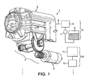
- FIG. 1 An exemplary motorized beverage machine 1 according to the invention is illustrated in Figure 1 .
- the machine comprises a brewing unit 2 which is connected to an electric motor 3 which drives transmission means 4 for moving brewing unit 2 from an open to a closed position and/or vice versa.
- Water supply means 5 are also provided as a part of machine 1.
- Such means 5 may include a water reservoir 6, a water pump 7 and a water heater 8.
- Water circulates in a water circuit 9 which is linked to brewing unit 2.
- circuit 9 is in fluid connection with brewing unit 2.
- Control means 10 are also provided in machine 1.
- Control means 10 include a control unit 11, sensors (not represented) and a user interface 12.
- Control unit 10 includes processor(s), memories and programs enabling to provide appropriate inputs to and receive outputs from the different activation means of the machine in particular, the pump, heater and motor.
- Control means 10 may be connected, e.g. wired or wireless, to user interface 12, pump 7, heater 8 and various sensors, such as flow-meters, temperature sensors, pressure sensors, ammeter (e.g. for measuring the current consumption of motor 3) such as a Hall sensor.
- control means 11 may control electric power switches and/or current and voltage regulators associated with motor 3, pump 7 and heater 8.
- brewing unit 2 has a first assembly 13 and a second assembly 14 which are movable relatively one another.
- assembly may refer to a single component assembling different functions, e.g. mechanical guiding function, mechanical holding function, mechanical piercing function, flow function, pressure function, etc..., and/or refer to a plurality of components assembling the desired functions.
- first assembly 13 is a rear injection assembly 13 and includes a capsule cage with injection blades 15.
- Front assembly 14 forms a beverage delivery assembly and includes a capsule delivery plate 16.
- Front assembly 14 is associated to an outer casing 17 and is movable therewith relatively to rear injection assembly 13 which remains fixed to a frame 18 of machine 1.
- Front delivery assembly 14 includes a beverage outlet 19.
- Front delivery assembly 14 is moved relatively to rear injection assembly 13 by means of motor 3 which drives transmission means 4.
- a passage 31 is provided between the first and second assemblies 13,14 for allowing the insertion of a capsule 30.
- the capsule may be positioned in an intermediate position, for example as described in EP 1 646 305 or WO 2009/043630 .
- a brewing chamber 29 is formed in the closed position ( Fig. 3 ).
- Brewing chamber 29 is occupied at least partially by a capsule 30 in a normally closed position of the brewing unit ( figure 4 ).
- the capsule may be of any type and should simply be compatible with brewing chamber 29 and passage 31 for being handled by the assemblies during closure and opening of the brewing unit. Suitable capsules and brewing chambers are for instance disclosed in EP 0 512 468 , EP 0 512 470 and EP 2 068 684 .
- Transmission means 4 may include various mechanical systems. Transmission means 4 may have a force transmission ratio from the motor to the assembly of at least 1:50, in particular from 1:100 to 1:300 to 1:500.
- transmission means 4 includes a gear assembly 20 linked to a cam 22 and cam-follower 23.
- cam 22 comprise a pair of elongated grooves located on each side of casing 17.
- Gear assembly 20 comprises a worm drive 21 connected to the motor axle (i.e. to the rotor of motor 3) .
- Worm drive 21 operates a large gear 24, e.g. a spur gear or helical gear, which is fixed to an axle 25 on which sit two lateral smaller gears 26, 27, e.g. spur gears or helical gears or friction gears.
- the smaller gears 26, 27 drives a pair of gear segments 28, e.g.
- gear segments 28 with cam-followers 23 are positioned such that the brewing pressure is absorbed across the gear segments without it being transmitted to the rest of the drive system, e.g. radially across the gear segments.
- the brewing pressure can be absorbed by the drive system by a suitable configuration.
- the gear ratio between worm drive 21 and large gear 24 may be in the range of 1:25 to 1:100, such as 1:50 to 1:80.
- the gear ratio between small gear 27 and gear segment 28 can be in the range of 1:3 to 1:10, in particular in the range of 1:5 to 1:8.
- worm drive 21 in transmission 4 can make this transmission unidirectional. In other words, force and movement can only be transmitted from motor 3 to transmission 4 and not vice versa, worm drive 21 acting as a stop in the opposite direction. Hence, no further stop means is needed to maintain the assemblies in a given position. It is sufficient to interrupt the powering of motor 3 to secure assemblies 13,14 in a given position, in particular in the closed or open position.
- both open and closed end positions are geometrically made as "hard stops” with no end switches or sensors.
- the input for the motor control may involve the user-interface, the current absorption of the motor and a timer of the control unit.
- two different typical curves 40,41 can be detected over time, e.g. by measuring the power consumption of motor 3, for example by measuring the current consumption of motor 3, in particular when motor 3 is a DC motor, e.g. operated at generally constant voltage.
- Curve 40 represents the evolution over time of the current consumption of motor 3 in the "capsule closure mode".
- the closed state of brewing unit 2 in the capsule closure mode is represented in Figure 4 with a capsule 30 enclosed in the closed brewing chamber.
- Curve 41 represents the evolution of the current consumption of motor 3 in the "empty closure mode".
- the closed state of brewing unit 2 in the empty closure mode is represented in Figure 3 .
- curves 40,41 correspond to a closure movement of assemblies 13,14 of brewing unit 2.
- curves can be determined for the opening movements, e.g. with and without capsule 30 inbetween assemblies 13,14.
- Such opening curves can be used as a reference set to detect possible disturbances of an opening movement of assemblies 13,14, e.g. jamming of a human body part such as a finger between a housing of the machine and a therein movable assembly of brewing unit 2.
- Control unit 10 of machine 1 is configured for comparing the variation of the actual current consumption to referential curves 40 and 41 depending on the relevant mode the brewing unit is engaged in. Such configuration is obtained by software.
- a brewing cycle can be initiated.
- the start of brewing cycle can be triggered by a command or request on the user's interface 12. Alternatively, the start of the brewing cycle can be triggered automatically by the reaching of the closed position.
- a rinsing and/or de-scaling mode with reduced temperature to allow optimal de-scaling and/or save energy is initiated in the closed position ( Figure 3 ).
- the start of rinsing and/or de-scaling cycle can also be triggered by a command or request on the user's interface 12. Alternatively, the start of the rinsing and/or de-scaling cycle can be triggered automatically by the reaching of the closed position.
- a cup-preheating mode may be initiated that involves the dispensing of heated water into a user-cup for preheating thereof prior to preparing and dispensing a beverage. Preheating of the cup may be carried out at beverage preparation temperature or at a reduced temperature.
- curve 40 illustrating an exemplary evolution of current consumption over time by motor 3 when a capsule 30 is inserted into brewing unit 2 includes various phases:
- An initial portion 401 i.e. a sharp increase of current consumption reflects the start of motion of the movable assembly, in particular the power consumption needed to overcome the static friction forces.
- a second portion 402 starts at a level slightly below the top of portion 401 (the dynamic friction forces being lower than the static friction forces) and increases slowly. This portion illustrates the increasing resistance caused by a capsule 30 progressively entering brewing chamber 29 during closure.
- a maximum 403 is reached when capsule 30 is forced out of an intermediate position in which it is supported by stop members, e.g. as explained in EP 2 103 236 . Thereafter, the current consumption drops slightly until it reaches a minimum 404.
- the current consumption 405,406,407 increases due to the deformation and progressive piercing of capsule 30 by blades 15 during closure.
- the more or less flat portion 408 represents the final approach of the assemblies.
- the current increase 409 reflects the power needed to stress a biasing spring (not shown) for a play take-up between the assemblies in the closed position. Once the current consumption reaches maximum 410, the maximum power is consumed by motor 3 which indicates that the motor 3 is blocked: the assemblies are in their closed position.
- Curve 41 illustrating an exemplary evolution of current consumption over time by motor 3 when no capsule is inserted into brewing unit 2, includes various phases:
- the time needed for closing the assemblies when no capsule is inserted into brewing unit 2 is slightly shorter, approx 0.5 sec, than when motor 3 has to overcome additional forces caused by the presence of a capsule 3.
- closure can be achieved within 2 or 2.5 sec, as illustrated with this particular embodiment of the invention.
- the time needed for opening of closing the assemblies of a brewing unit may typically be in the range of 1 to 10 seconds.
- a safety input can be activated.
- the safety input preferably comprises the operation of inverting the motor action to move the movable assembly back into the open position.
- the safety input may amount to reducing or stopping the drive action of the motor. This safety measure protects for example the user from jamming a finger in the running mechanism.
- the safety input may be triggered when the resistance against closure of the assemblies exceeds 50, 80, 100, 125 or 150 N before reaching the closed position.
- the safety input may be triggered when an excessive resistance occurs at a distance between the assemblies before closure which is greater than 1 or 2 mm, in particular greater than 3 mm or 4 mm.
- the gear assembly is preferably configured to provide a gear ratio of at least 1:100, preferably comprised between 1:200 and 1:500 such as between 1:250 and 1:450, e.g. 1:300. Due to this relatively high gear ratio, another benefit of the present invention comes from the possibility to use relatively low power motor, for example comprised between 20 - 50 mNm.
- Motor 3 can be a low power motor configured to generate a maximum torque of no more than 50 mNm; and/or consume a maximum power of no more than 50 watt, for driving movable assembly 14 between the open and closed positions. and/or not exceeding 50 watt.
- motor 3 is arranged to generate a maximum torque of at least 20 mNm, in particular a maximum torque in the range of 25 to 40 mNm.
- Motor 3 can be arranged to consume a maximum power in the range of 7 to 25 watt, in particular 10 to 15 watt.
- the motor can have an angular speed of up to 10K RPM, such as from 0 to 5000 RPM.
- a low power motor By providing a low power motor, it is possible to simplify the construction and control of the motorized machine. As compared to high power motors, a low power motor has a smaller inertia due to the reduced mechanical inertia and lower power load. Hence, temporary variations of the force (or torque) required from the motor, e.g. to overcome an obstacle or additional friction, is not or less absorbed by the dampening effect of the mechanical inertia and electric load of the motor but timely translated in a temporary increase of required electric powering of the motor. Moreover, since the motor has a lower mechanical and electric inertia, interrupting the powering of the motor is not followed by a significant discharge of the energy load (mechanical and electric) of the motor into the mechanical system.
Landscapes
- Engineering & Computer Science (AREA)
- Food Science & Technology (AREA)
- Mechanical Engineering (AREA)
- Apparatus For Making Beverages (AREA)
- Devices For Dispensing Beverages (AREA)
Description
- The present invention relates to a beverage machine for the preparation of a beverage from an ingredient capsule. More particularly, the machine has a motorized brewing unit and a control for closing the brewing unit in a convenient and safe manner. The brewing unit comprises in particular: first and second assemblies each delimiting a part of a brewing chamber; and an ingredient capsule between the assemblies. Thus, the invention also concerns a use of an ingredient capsule for implementing such a beverage machine with a capsule.
- For the purpose of the present description, a "beverage" is meant to include any human-consumable liquid substance, such as tea, coffee, hot or cold chocolate, milk, soup, baby food, etc... A "capsule" is meant to include any pre-portioned beverage ingredient, such as a flavouring ingredient, within an enclosing packaging of any material, in particular an airtight packaging, e.g. plastic, aluminium, recyclable and/or biodegradable packagings, and of any shape and structure, including soft pods or rigid cartridges containing the ingredient.
- Certain beverage preparation machines use capsules containing ingredients to be extracted or to be dissolved and/or ingredients that are stored and dosed automatically in the machine or else are added at the time of preparation of the drink. Some beverage machines possess filling means that include a pump for liquid, usually water, which pumps the liquid from a source of water that is cold or indeed heated through heating means, e.g. a thermoblock or the like.
- For instance, it is known to prepare coffee automatically by supplying a certain amount of loose ground coffee into an infusion chamber, compressing the loose ground coffee by a motorized piston in the chamber and circulating heated water through the chamber to infuse the coffee. By controlling the motorized piston, the ground coffee is appropriately pressed to obtain the desired infusion conditions when the heated water is circulated through the ground coffee. After infusion, the ground coffee may be further squeezed by the piston before the ground coffee is removed from the chamber. Examples of such systems are disclosed in
EP 627 186 DE 20 2007 005 791EP 937 432 US 2005/0193891 . - Especially in the field of coffee preparation, machines have been widely developed in which a capsule containing beverage ingredients is inserted in a brewing device. The brewing device is tightly closed about the capsule, water is injected at the first face of the capsule, the beverage is produced in the closed volume of the capsule and a brewed beverage can be drained from a second face of the capsule and collected into a receptacle such as a cup or glass.
- Brewing devices have been developed to facilitate insertion of a "fresh" capsule and removal of the capsule upon use.
-
WO 2005/004683 andWO 2007/135136 relate to such brewing devices. The devices comprise a frame, a fixed holding part for the capsule, a movable holding part which is mounted relative to the frame in a sliding relationship, one or two knuckle joint mechanisms that provide a mechanical system which enables to close in a steady and fluid-tight manner the holding parts about the capsule while also resisting to the counter-force acting while re-opening and generated by the internal brewing pressure, and a handle for directly levering the knuckle joint mechanism. Such a device forms a simple assembly enabling insertion of the capsule by vertical fall through a passage in the frame and removal of the used capsule in the same direction as the insertion direction. The handle may serve to cover and uncover the passage for the capsule. The movable parts of the brewing device are actuated manually via the handle. The manual force required to move the movable parts varies during closure and opening of the machine and depends on the dimensional tolerances of the capsules used and the positioning and nature of the capsules as well as the temperature of the brewing unit. -
WO 2009/043630 discloses a beverage preparation machine including a brewing unit having a front part with a passage for inserting a capsule into the brewing unit. The front part is arranged to telescope out of the machine's housing for uncovering the passage for inserting a capsule into the brewing unit and telescopes into the brewing unit for sliding the passage under the housing and thus covering the passage by the housing. - From a different approach, the actuation of the movable part of the brewing device may be motorized.
EP 1 767 129 - An object of the invention is to provide a motorized closure function of the brewing unit for providing more convenience in loading and ejection of the ingredient capsule and reducing user's intervention. Another object is to provide a safe operation by reducing the risk of injuries while using a motorized beverage machine. Another object is to provide added value functionalities such as semi-automatic or automatic brewing, rinsing and/or de-scaling modes. Another object is to control optimal conditions for rinsing and/or de-scaling the machine.
- One or more of these objects are meet by a motorized brewing machine according to the first independent claim. The dependent claims further provide solutions to these objects and/or additional benefits.
- The invention relates to a motorized machine for preparing and dispensing a beverage and more particularly to a beverage machine having a motorized brewing unit. For instance, the machine is a coffee, tea, chocolate, cacao, milk or soup preparation machine. In particular, the machine is arranged for preparing within a beverage processing module a beverage by passing hot or cold water or another liquid through a capsule containing an ingredient, such as a flavouring ingredient, of the beverage to be prepared, such as ground coffee or tea or chocolate or cacao or milk powder.
- Such beverage preparation typically includes the mixing of a plurality of beverage ingredients, e.g. water and milk powder, and/or the infusion of a beverage ingredient, such as an infusion of ground coffee or tea with water. For instance, a predetermined amount of beverage is formed and dispensed on user-request, which corresponds to a serving. The volume of such a serving may be in the range of 25 to 200 ml, e.g. the volume for filling a cup or mug, depending on the type of beverage. Formed and dispensed beverages may be selected from ristrettos, espressos, lungos, cappuccinos, café latte, americano coffees, teas, etc... In particular, a coffee machine may be configured for dispensing espressos, e.g. an adjustable volume of 20 to 60 ml per serving, and/or for dispensing lungos, e.g. a volume in the range of 70 to 150 ml per serving.
- In particular, the motorized beverage machine has a brewing unit that comprises a first assembly and a second assembly cooperating together, each assembly delimiting part of a brewing chamber for containing an ingredient capsule. At least one of these assemblies is:
- movable away from the cooperating assembly into an open position within the machine for forming between the assemblies a passage for inserting into and/or removing from the brewing unit the ingredient capsule; and
- movable to (e.g. towards) the cooperating assembly into a closed position for forming the brewing chamber.
- The assemblies are relatively movable to one another. One assembly may be fixed in the machine, e.g. in the main frame or outer housing of the machine, and the other assembly may be movable thereto. Alternatively, both assemblies may be movable in the machine, e.g. in the main frame or outer housing of the machine.
- The machine comprises activation means that include:
- a motor for driving the movable assembly of the brewing unit between the open and closed positions;
- a transmission means for transmitting a drive action from the motor to the movable assembly, e.g. one or more transmission gears and/or belts and/or cardans;
- water supply means for supplying heated water to the brewing chamber, e.g. a water source with a pump and/or a heater and a control unit such as a PCB with a controller and optional memory device and/or other electronic components (i.e. a PCBA "Printed Circuit Board Assembly"); and
- control means for controlling the drive action of the motor, e.g. a control unit such as a PCB with a controller or a PCBA.
- In accordance with the invention, the motorized beverage machine comprises means for measuring at least one electrical parameter representative of the motor power consumption and for comparing the evolution of this measured parameter as a function of time during the transfer of the assembly from the open to the closed position to a set reference and means for providing an input to at least one of said activation means as a result of the compared evolution of said measured parameter.
- Hence, the circumstances under which the assemblies are moved to the open and/or closed position can be monitored by monitoring the power consumption of the motor. In particular, the required mechanical output energy of the motor to produce a movement is directly linked to its consumed input energy, e.g. electric energy, can be measured.
- The set reference may be based on a power consumption modelisation and/or an empiric power consumption measure under predetermined conditions, e.g. with or without ingredient capsule in the brewing unit, specific environment of use, etc... The set reference typically includes a tolerance margin to take into account variations that may occur e.g. due to the environment of use and/or manufacturing tolerances and/or handling tolerances.
- For example, the motor is controlled to produce an output movement, e.g. rotation of a rotor, at a predetermined speed and/or to operate at a predetermined input voltage for example at constant voltage. To maintain the predetermined speed and/or voltage, the input powering of the motor can be adjusted in line with the needed output powering, e.g. angular speed and torque (depending on the constraints under which the motor has to operate in a given circumstance). In particular, the power supply of the motor may be arranged to control the motor's input voltage and the motor can be arranged to draw the required amount of current needed to maintain the input voltage. By measuring the required motor input powering to maintain the desired motor output speed and/or the input voltage, the mechanical constraints exercised against the motor output can be determined. Such constraints may correspond to normal operation of the motorized machine, e.g. opening or closing the brewing unit assemblies with or without a capsule ingredient, or to an abnormal operation, e.g. an interference with an obstacle preventing normal opening or closing, such as a human body part e.g. a finger, caught inbetween the assemblies or inhibiting reopening of the assemblies, e.g. jamming of the brewing unit. In the former case (normal operation), the motorized beverage machine may be configured to allow a corresponding operation, e.g. beverage preparation or cleaning, or to carry it out automatically. In the latter case (abnormal operation), a safety mode may be provided, e.g. to stop closure or reopen the assemblies when an undesired obstacle is caught between the assemblies, or stop the motor when the brewing unit is jammed e.g. to prevent undesired stress in the machine and allow for example manual unjamming by a user and/or service person, as appropriate.
- A safety input is typically provided to the motor when detecting an abnormal variation of the measured parameter relative to the set reference. The variation may be deemed abnormal when the measured parameter:
- exceeds a level that is at least 20% above the set reference, in particular 30 or 40% thereabove such as 50% thereabove; and/or
- corresponds to a resistance against closure caused by the presence of an obstacle, in particular a human body part such as a finger, inbetween the assemblies moving towards the closed position and prior to reaching thereof, for example a resistance between the assemblies of the brewing unit in the range from 50 to 200 N, in particular from 75, 100 or 120 to 130 or 150 N.
- Providing a reference set that includes a tolerance range, e.g. 20, 30, 40 or even 50% relative to a median or average reference set may be appropriate to take into account normal variations of mechanical effects occurring in the machine, such as variations of a friction coefficient, temperature and humidity as well as manufacturing tolerances.
- The safety input may comprise inverting the motor action to move the movable assembly in open position or reducing or stopping the drive action of the motor.
- The control means can be configured to detect the abnormal variation in comparison to a referential curve representing the normal evolution of the electrical parameter as a function of time corresponding to:
- a mode in which the movable assembly is moved into a closed position with an ingredient capsule inserted in the brewing chamber (hereinafter the "Capsule closure mode"); and/or
- a mode in which the movable assembly is moved into a closed position with no capsule inserted in the brewing chamber (hereinafter the "Empty closure mode").
- A water supply mode consisting of supplying heated water to the brewing chamber may be initiated when no abnormal variation of the measured parameter relative to the set reference has been detected and the assembly is in a closed position ("Capsule closure mode or empty closure mode"). The supplying of heated water may involve the circulation, e.g. by using a pump, of water from a source, e.g. a water tank, and/or the heating of water, e.g. continuous or batch heating, to the brewing chamber. The supply of heated water may be controlled, e.g. via one or more temperature sensors, pressure sensors and/or flowmeters, to adjust the heating and flow characteristics of the supplied heated water.
- Optionally, the control means comprise a user-interface to selectively initiate the water supply mode. Hence, water may be circulated to the brewing chamber automatically or upon a user-request via the user-interface.
- The control means may be configured to initiate a brewing mode when the measured parameter matches the referential curve (including a possible tolerance) corresponding to the "capsule closure mode".
- The control means can be configured to initiate a rinsing and/or de-scaling mode when the measured parameter matches the referential curve corresponding to the "empty closure mode". In particular, the control means can be configured so that said supplied water is heated at a temperature, such as in the range of 55 to 85°C, lower than the normal brewing temperature, such as in the range of 85 to 98°C.
- At least one measured parameter may represent the current consumption of the motor.
- The transmission means may include a gear assembly.
- The transmission means, in particular a gear assembly, may be configured to provide a transmission ratio of at least 1:100, preferably comprised between 1:200 and 1:300.
- The control means can be free of end position sensors in the open position and/or in the closed position. In this case, the measure of the power consumption by the motor may be used to determine the open position and/or closed position. The measure of the power consumption may be correlated with a time evolution to link the consumption to a time-based expected position of the movable assembly, for instance to distinguish the power consumption resulting from reaching an end position from the power consumption resulting from interference with an intermediate undesired obstacle.
- Alternatively, the control means may include at least one end position sensor, e.g. two end position sensors in particular for detecting the open position and/or the closed position.
- The motorized beverage machine may include an ingredient capsule between the first and second assemblies, the motor being controlled by the control means to move the assemblies from the open position to the closed position to form the brewing chamber to contain the ingredient capsule, the measuring means of the control means being arranged to measure at least one parameter representative of the power consumption of the motor during motion of the assemblies to the closed position with the capsule between the closing assemblies, the comparing means of the control means being arranged to compare the evolution of said measured parameter to the set reference, the input means of the control means being arranged to provide to at least one of said activation means the input resulting from said comparison.
- The control means can be configured to detect any abnormal variation in comparison to a referential curve representing the normal evolution of the electrical parameter as a function of time and to:
- initiate a water supply mode when no abnormal variation of the measured parameter relative to the set reference has been detected and the assembly is in a closed position; and/or
- provide a safety input to the motor when an abnormal variation of the measured parameter relative to the set reference is detected.
- The invention will now be described with reference to the schematic drawings, wherein:
-
Figure 1 is a partly schematic and partly perspective view of a beverage machine according to the invention; -
Figure 2 shows a partial cross-sectional perspective representation of a brewing unit of the beverage machine offigure 1 in open position; -
Figure 3 shows a partial cross-sectional perspective representation of a closed brewing unit of the beverage machine offigure 1 in an "empty closure mode"; -
Figure 4 shows a partial cross-sectional perspective representation of a closed brewing unit of the beverage machine offigure 1 in a "capsule closure mode"; and -
Figure 5 shows a graphic of referential curves of the current absorption of the motor as a function of time in a "capsule closure mode" and in an "empty closure mode". - An exemplary
motorized beverage machine 1 according to the invention is illustrated inFigure 1 . The machine comprises abrewing unit 2 which is connected to an electric motor 3 which drives transmission means 4 for movingbrewing unit 2 from an open to a closed position and/or vice versa. Water supply means 5 are also provided as a part ofmachine 1. Such means 5 may include a water reservoir 6, a water pump 7 and awater heater 8. Water circulates in awater circuit 9 which is linked tobrewing unit 2. Typically,circuit 9 is in fluid connection withbrewing unit 2. Control means 10 are also provided inmachine 1. Control means 10 include acontrol unit 11, sensors (not represented) and auser interface 12.Control unit 10 includes processor(s), memories and programs enabling to provide appropriate inputs to and receive outputs from the different activation means of the machine in particular, the pump, heater and motor. - Control means 10 may be connected, e.g. wired or wireless, to
user interface 12, pump 7,heater 8 and various sensors, such as flow-meters, temperature sensors, pressure sensors, ammeter (e.g. for measuring the current consumption of motor 3) such as a Hall sensor. In particular, control means 11 may control electric power switches and/or current and voltage regulators associated with motor 3, pump 7 andheater 8. - As shown in
Figures 2 and 3 ,brewing unit 2 has afirst assembly 13 and asecond assembly 14 which are movable relatively one another. - In the context of the present invention, "assembly" may refer to a single component assembling different functions, e.g. mechanical guiding function, mechanical holding function, mechanical piercing function, flow function, pressure function, etc..., and/or refer to a plurality of components assembling the desired functions.
- For instance,
first assembly 13 is arear injection assembly 13 and includes a capsule cage withinjection blades 15.Front assembly 14 forms a beverage delivery assembly and includes acapsule delivery plate 16.Front assembly 14 is associated to anouter casing 17 and is movable therewith relatively torear injection assembly 13 which remains fixed to aframe 18 ofmachine 1.Front delivery assembly 14 includes abeverage outlet 19. -
Front delivery assembly 14 is moved relatively torear injection assembly 13 by means of motor 3 which drives transmission means 4. - In the open position (
Fig. 2 ), apassage 31 is provided between the first andsecond assemblies capsule 30. The capsule may be positioned in an intermediate position, for example as described inEP 1 646 305WO 2009/043630 . - In the closed position (
Fig. 3 ), abrewing chamber 29 is formed. Brewingchamber 29 is occupied at least partially by acapsule 30 in a normally closed position of the brewing unit (figure 4 ). The capsule may be of any type and should simply be compatible withbrewing chamber 29 andpassage 31 for being handled by the assemblies during closure and opening of the brewing unit. Suitable capsules and brewing chambers are for instance disclosed inEP 0 512 468 ,EP 0 512 470 andEP 2 068 684 - Transmission means 4 may include various mechanical systems. Transmission means 4 may have a force transmission ratio from the motor to the assembly of at least 1:50, in particular from 1:100 to 1:300 to 1:500.
- In the embodiment illustrated in
Figs 1 to 4 , transmission means 4 includes agear assembly 20 linked to acam 22 and cam-follower 23. For a balanced transmission of the forces on casing 17,cam 22 comprise a pair of elongated grooves located on each side ofcasing 17.Gear assembly 20 comprises aworm drive 21 connected to the motor axle (i.e. to the rotor of motor 3) .Worm drive 21 operates alarge gear 24, e.g. a spur gear or helical gear, which is fixed to anaxle 25 on which sit two lateralsmaller gears gear segments 28, e.g. spur gears or helical gears or friction gears, which moves cam-follower 23 and, by way of consequence, movecam 22 with thecasing 17 from the opened to the closed position and vice versa. In the closedposition gear segments 28 with cam-followers 23 are positioned such that the brewing pressure is absorbed across the gear segments without it being transmitted to the rest of the drive system, e.g. radially across the gear segments. However, as explained hereafter, the brewing pressure can be absorbed by the drive system by a suitable configuration. - The gear ratio between
worm drive 21 andlarge gear 24 may be in the range of 1:25 to 1:100, such as 1:50 to 1:80. The gear ratio betweensmall gear 27 andgear segment 28 can be in the range of 1:3 to 1:10, in particular in the range of 1:5 to 1:8. - For instance, the use of a
worm drive 21 intransmission 4 can make this transmission unidirectional. In other words, force and movement can only be transmitted from motor 3 totransmission 4 and not vice versa,worm drive 21 acting as a stop in the opposite direction. Hence, no further stop means is needed to maintain the assemblies in a given position. It is sufficient to interrupt the powering of motor 3 to secureassemblies - In a possible solution, both open and closed end positions are geometrically made as "hard stops" with no end switches or sensors.
- The input for the motor control may involve the user-interface, the current absorption of the motor and a timer of the control unit.
- As illustrated in
Figure 5 , two differenttypical curves -
Curve 40 represents the evolution over time of the current consumption of motor 3 in the "capsule closure mode". The closed state ofbrewing unit 2 in the capsule closure mode is represented inFigure 4 with acapsule 30 enclosed in the closed brewing chamber. -
Curve 41 represents the evolution of the current consumption of motor 3 in the "empty closure mode". The closed state ofbrewing unit 2 in the empty closure mode is represented inFigure 3 . - Hence, curves 40,41 correspond to a closure movement of
assemblies brewing unit 2. Likewise, curves can be determined for the opening movements, e.g. with and withoutcapsule 30inbetween assemblies assemblies brewing unit 2. -
Control unit 10 ofmachine 1 is configured for comparing the variation of the actual current consumption toreferential curves - If a
capsule 30 is inserted inbrewing unit 2, and no abnormal variation of the current absorption is detected in comparison tocurve 40, e.g. no variation exceeding 20% of the typicalcurrent consumption curve 40, a brewing cycle can be initiated. The start of brewing cycle can be triggered by a command or request on the user'sinterface 12. Alternatively, the start of the brewing cycle can be triggered automatically by the reaching of the closed position. - If no capsule is inserted into
brewing chamber 2 and no abnormal variation of the variation of the current absorption is detected in comparison tocurve 41, a rinsing and/or de-scaling mode with reduced temperature to allow optimal de-scaling and/or save energy is initiated in the closed position (Figure 3 ). The start of rinsing and/or de-scaling cycle can also be triggered by a command or request on the user'sinterface 12. Alternatively, the start of the rinsing and/or de-scaling cycle can be triggered automatically by the reaching of the closed position. If no capsule is inserted intobrewing chamber 2 and no abnormal variation of the variation of the current absorption is detected in comparison tocurve 41, a cup-preheating mode may be initiated that involves the dispensing of heated water into a user-cup for preheating thereof prior to preparing and dispensing a beverage. Preheating of the cup may be carried out at beverage preparation temperature or at a reduced temperature. - More specifically,
curve 40 illustrating an exemplary evolution of current consumption over time by motor 3 when acapsule 30 is inserted intobrewing unit 2, includes various phases: - An
initial portion 401, i.e. a sharp increase of current consumption reflects the start of motion of the movable assembly, in particular the power consumption needed to overcome the static friction forces. Asecond portion 402, starts at a level slightly below the top of portion 401 (the dynamic friction forces being lower than the static friction forces) and increases slowly. This portion illustrates the increasing resistance caused by acapsule 30 progressively enteringbrewing chamber 29 during closure. A maximum 403 is reached whencapsule 30 is forced out of an intermediate position in which it is supported by stop members, e.g. as explained inEP 2 103 236capsule 30 byblades 15 during closure. The more or lessflat portion 408 represents the final approach of the assemblies. Thecurrent increase 409 reflects the power needed to stress a biasing spring (not shown) for a play take-up between the assemblies in the closed position. Once the current consumption reaches maximum 410, the maximum power is consumed by motor 3 which indicates that the motor 3 is blocked: the assemblies are in their closed position. -
Curve 41 illustrating an exemplary evolution of current consumption over time by motor 3 when no capsule is inserted intobrewing unit 2, includes various phases: -
Portion 411 corresponds toportion 401, i.e. the movable assembly is put in motion. Once the assembly is motion, portions 412,413 and 414 illustrate essentially the force distribution of the rotating cam-follower 23 moving in thestraight grooves 22 andassembly 13 moving generally perpendicularly to the direction ofgrooves 22. Portion 416,417 illustrate the power consumption increase due to stressing the biasing spring. Like above, once the current consumption reaches maximum 417, the maximum power is consumed by motor 3 which indicates that the resistance against motor 3 is complete: the assemblies are in their closed position. - As illustrated in
Fig. 5 by way of example, the time needed for closing the assemblies when no capsule is inserted intobrewing unit 2, is slightly shorter, approx 0.5 sec, than when motor 3 has to overcome additional forces caused by the presence of a capsule 3. Overall, closure can be achieved within 2 or 2.5 sec, as illustrated with this particular embodiment of the invention. - The time needed for opening of closing the assemblies of a brewing unit may typically be in the range of 1 to 10 seconds.
- When the measure of the current absorption does not match the two above mentioned
curves - The gear assembly is preferably configured to provide a gear ratio of at least 1:100, preferably comprised between 1:200 and 1:500 such as between 1:250 and 1:450, e.g. 1:300. Due to this relatively high gear ratio, another benefit of the present invention comes from the possibility to use relatively low power motor, for example comprised between 20 - 50 mNm.
- Motor 3 can be a low power motor configured to generate a maximum torque of no more than 50 mNm; and/or consume a maximum power of no more than 50 watt, for driving
movable assembly 14 between the open and closed positions. and/or not exceeding 50 watt. For instance, motor 3 is arranged to generate a maximum torque of at least 20 mNm, in particular a maximum torque in the range of 25 to 40 mNm. Motor 3 can be arranged to consume a maximum power in the range of 7 to 25 watt, in particular 10 to 15 watt. - The motor can have an angular speed of up to 10K RPM, such as from 0 to 5000 RPM.
- By providing a low power motor, it is possible to simplify the construction and control of the motorized machine. As compared to high power motors, a low power motor has a smaller inertia due to the reduced mechanical inertia and lower power load. Hence, temporary variations of the force (or torque) required from the motor, e.g. to overcome an obstacle or additional friction, is not or less absorbed by the dampening effect of the mechanical inertia and electric load of the motor but timely translated in a temporary increase of required electric powering of the motor. Moreover, since the motor has a lower mechanical and electric inertia, interrupting the powering of the motor is not followed by a significant discharge of the energy load (mechanical and electric) of the motor into the mechanical system. It follows that by using a low power motor, the actual mechanical behaviour of the relatively movable assemblies can be monitored via the power consumption of the motor. Moreover, the machine does not require end position sensors to stop the motor when it is about to reach the end positions. The reaching of an obstacle at the end position can be nearly instantaneously identified by monitoring the power consumption of the motor the powering of which can be stopped without the risk of the motor forcing the assemblies detrimentally beyond the end position by discharging its mechanical and electric inertia.
Claims (22)
- A motorized beverage machine (1) having a brewing unit (2) that comprises a first assembly (13) and a second assembly (14) cooperating together, each assembly delimiting part of a brewing chamber (29) for containing an ingredient capsule (30), at least one of said assemblies being:- movable away from the cooperating assembly into an open position within said machine for forming between said assemblies a passage (31) for inserting into and/or removing from the brewing unit said ingredient capsule; and- movable to the cooperating assembly into a closed position for forming said brewing chamber,such machine comprising activation means including:- a motor (3) for driving said movable assembly between said open and closed positions;- a transmission means (4) for transmitting a drive action from the motor to the movable assembly;- water supply means (5) for supplying heated water to the brewing chamber; and- control means (10) for controlling the drive action of the motor,characterised in that the control means (10) comprise:- means for measuring at least one electrical parameter representative of a consumption of power by the motor;- means for comparing to a set reference (40,41) an evolution of said measured parameter as a function of time during the transfer of the assembly from the open to the closed position; and- means for providing to at least one of said activation means an input resulting from the comparison of the evolution of said measured parameter to the set reference.
- The machine of claim 1, wherein a safety input is provided to the motor (3) when detecting a variation of the measured parameter relative to the set reference (40,41) which is abnormal.
- The machine of claim 2, wherein the variation is deemed abnormal when the measured parameterexceeds a level that is at least 20% above the set reference (40,41), in particular 30 or 40% thereabove such as 50% thereabove.
- The machine of claim 2 or 3, wherein the safety input comprises inverting the motor action to move the movable assembly (14) into the open position or reducing or stopping the drive action of the motor.
- The machine of any one of claims 2 to 4, wherein the control means (10) is configured to detect the abnormal variation in comparison to a referential curve (40,41) representing the normal evolution of the electrical parameter as a function of time corresponding to:- a mode in which the movable assembly (14) is moved into a closed position with an ingredient capsule (30) inserted in the brewing chamber (29) (hereinafter the "Capsule closure mode"); and/or- a mode in which the movable assembly is moved into a closed position with no capsule inserted in the brewing chamber (hereinafter the "Empty closure mode").
- The machine of claim 5, wherein a water supply mode consisting of supplying heated water to the brewing chamber (29) is initiated when no abnormal variation of the measured parameter relative to the set reference (40,41) has been detected and the assembly is in a closed position ("Capsule closure mode or empty closure mode"), the control means optionally comprising a user interface (11) to selectively initiate the water supply mode.
- The machine of claim 6, wherein the control means (10) is configured to initiate a brewing mode when the measured parameter matches the referential curve (40) corresponding to the "capsule closure mode".
- The machine of claim 6 or 7, wherein the control means (10) is configured to initiate a rinsing and/or de-scaling mode when the measured parameter matches the referential curve corresponding to the "empty closure mode" (41), the control means being in particular configured so that said supplied water is heated at a temperature, such as in the range of 55 to 85°C, lower than the normal brewing temperature, in particular in the range of 85 to 98°C.
- The machine of any preceding claim, wherein the at least one measured parameter represents the current absorption of the motor (3).
- The machine of any preceding claim, wherein the transmission means (4) comprises a gear assembly (20).
- The machine of claim 10, wherein the gear assembly (20) is configured to provide a gear ratio of at least 1:100, preferably comprised between 1:200 and 1:300.
- The machine of any preceding claim, wherein the control means (10) is free of end position sensors in the open position and/or closed position.
- The machine of any one of claims 1 to 12, wherein the control means comprises at least one end position sensor.
- The machine of any preceding claim, which comprises an ingredient capsule (30) between the first and second assemblies (13,14), the motor (3) being controlled by the control means (10) to move the assemblies from the open position to the closed position to form the brewing chamber (29) to contain the ingredient capsule, the measuring means of the control means being arranged to measure at least one parameter representative of the power consumption of the motor during motion of the assemblies to the closed position with the capsule between the closing assemblies, the comparing means of the control means being arranged to compare the evolution of said measured parameter to the set reference (40,41), the input means of the control means being arranged to provide to at least one of said activation means the input resulting from said comparison.
- The machine of claim 14, wherein the first assembly (13) is a rear injection assembly and includes a capsule cage with injection blades (15) and wherein the front assembly (14) forms a beverage delivery assembly and includes a capsule delivery plate (16), such as a delivery assembly (14) including a beverage outlet (19), optionally the front assembly (14) being associated to an outer casing (17) and being movable therewith relatively to rear injection assembly (13) which remains fixed to a frame (18).
- The machine of claim 15, wherein the at least one measured parameter represents the current absorption of the motor (3) when said at least one of said assemblies (13,14) is moved from the open to the closed position, the current absorption evolving over time along:- an initial portion (401) forming a sharp increase of current consumption reflecting a start of motion of said at least one of said assemblies (13,14);- a second portion (402) that starts at a level slightly below a top of the initial portion (401) and that slowly increases due to an increasing resistance by the capsule (30) progressively entering the brewing chamber (29) up to a maximum (403) where the capsule is forced out of an intermediate position in which it is supported by stop members;- another portion (403,404) that slightly drops from the maximum (403) to a minimum (404);- a further portion (405,406,407) that increases due to a deformation and progressive piercing of the capsule (30) by blades (15);- a yet further portion (408) that is more or less flat during a final approach of the assemblies (13,14); and- a portion (409) which increases due to a stressing of a biasing spring for taking up a play between the assemblies in the closed position and which reaches a maximum (410) whereby a maximum of power is consumed by the motor (3) indicating that the motor is blocked and that the assemblies are in their closed position.
- The machine of claim 14, 15 or 16, wherein the control means (10) is configured to detect any abnormal variation in comparison to a referential curve (40,41) representing the normal evolution of the electrical parameter as a function of time and to:- initiate a water supply mode when no abnormal variation of the measured parameter relative to the set reference has been detected and the assembly (14) is in a closed position; and/or- provide a safety input to the motor (3) when an abnormal variation of the measured parameter relative to the set reference is detected.
- A method for operating a motorized beverage machine comprising a capsule (30) between the first and second assemblies (13,14) as defined in any one of claims 14 to 17, comprising:- controlling the motor (3) by the control means (10) to move the assemblies from the open to the closed position to form the brewing chamber (29) to contain the ingredient capsule;- measuring at least one parameter representative of the power consumption of the motor during motion of the assemblies to the closed position with the capsule between the closing assemblies;- comparing the evolution of said measured parameter to the set reference (40,41); and- providing, by the input means of the control means, to at least one of said activation means the input resulting from said comparison.
- A use, of an ingredient capsule (30),
for implementing a motorized beverage machine comprising a capsule between the first and second assemblies (13,14) as defined in any one of claims 14 to 17, or
for carrying out the method of claim 18. - The use of claim 19, wherein the ingredient capsule (30) is of a type that:- can be inserted into the passage (31) and positioned in an intermediate position when said at least one of said assemblies (13,14) is in the open position; and- occupies partly the brewing chamber (29) when said at least one of said assemblies (13,14) is in the closed position.
- The use of claim 20, wherein the ingredient capsule (30) is of a type that can be positioned in an intermediate position when said at least one of said assemblies (13,14) is in the open position.
- Use, for an ingredient capsule (30) for a use as defined in any one of claims 19 to 21, of at least one ingredient for preparing coffee, tea, chocolate, cacao, milk, baby food and soup.
Priority Applications (2)
| Application Number | Priority Date | Filing Date | Title |
|---|---|---|---|
| EP15164569.4A EP2926698B1 (en) | 2010-08-27 | 2011-05-05 | Controlled motorized brewing unit |
| EP11719510.7A EP2608705B2 (en) | 2010-08-27 | 2011-05-05 | Controlled motorized brewing unit |
Applications Claiming Priority (3)
| Application Number | Priority Date | Filing Date | Title |
|---|---|---|---|
| EP10174412 | 2010-08-27 | ||
| PCT/EP2011/057233 WO2012025258A1 (en) | 2010-08-27 | 2011-05-05 | Controlled motorized brewing unit |
| EP11719510.7A EP2608705B2 (en) | 2010-08-27 | 2011-05-05 | Controlled motorized brewing unit |
Related Child Applications (2)
| Application Number | Title | Priority Date | Filing Date |
|---|---|---|---|
| EP15164569.4A Division EP2926698B1 (en) | 2010-08-27 | 2011-05-05 | Controlled motorized brewing unit |
| EP15164569.4A Division-Into EP2926698B1 (en) | 2010-08-27 | 2011-05-05 | Controlled motorized brewing unit |
Publications (3)
| Publication Number | Publication Date |
|---|---|
| EP2608705A1 EP2608705A1 (en) | 2013-07-03 |
| EP2608705B1 true EP2608705B1 (en) | 2015-06-24 |
| EP2608705B2 EP2608705B2 (en) | 2024-03-06 |
Family
ID=44065470
Family Applications (3)
| Application Number | Title | Priority Date | Filing Date |
|---|---|---|---|
| EP11719510.7A Active EP2608705B2 (en) | 2010-08-27 | 2011-05-05 | Controlled motorized brewing unit |
| EP15164569.4A Active EP2926698B1 (en) | 2010-08-27 | 2011-05-05 | Controlled motorized brewing unit |
| EP11718373.1A Active EP2608704B1 (en) | 2010-08-27 | 2011-05-05 | Simple motorized brewing unit |
Family Applications After (2)
| Application Number | Title | Priority Date | Filing Date |
|---|---|---|---|
| EP15164569.4A Active EP2926698B1 (en) | 2010-08-27 | 2011-05-05 | Controlled motorized brewing unit |
| EP11718373.1A Active EP2608704B1 (en) | 2010-08-27 | 2011-05-05 | Simple motorized brewing unit |
Country Status (17)
| Country | Link |
|---|---|
| US (2) | US10285534B2 (en) |
| EP (3) | EP2608705B2 (en) |
| JP (2) | JP5871927B2 (en) |
| KR (2) | KR20130095757A (en) |
| CN (2) | CN103209622B (en) |
| AU (2) | AU2011295341C1 (en) |
| BR (2) | BR112013004767B1 (en) |
| CA (2) | CA2809078C (en) |
| CH (1) | CH705749B1 (en) |
| DE (1) | DE112011102829T5 (en) |
| DK (1) | DK201300013U4 (en) |
| ES (3) | ES2546489T3 (en) |
| MX (2) | MX341681B (en) |
| PT (3) | PT2608704T (en) |
| RU (1) | RU2560911C2 (en) |
| WO (2) | WO2012025259A1 (en) |
| ZA (2) | ZA201302271B (en) |
Cited By (1)
| Publication number | Priority date | Publication date | Assignee | Title |
|---|---|---|---|---|
| EP3175747A1 (en) | 2015-12-03 | 2017-06-07 | Qbo Coffee GmbH | Machine for making beverages |
Families Citing this family (82)
| Publication number | Priority date | Publication date | Assignee | Title |
|---|---|---|---|---|
| EP2608705B2 (en) * | 2010-08-27 | 2024-03-06 | Société des Produits Nestlé S.A. | Controlled motorized brewing unit |
| JP2014504513A (en) * | 2011-01-03 | 2014-02-24 | ネステク ソシエテ アノニム | Electric beverage machine with mechanical transmission |
| ITVR20110179A1 (en) * | 2011-09-19 | 2013-03-20 | Caffita System Spa | INFUSION DEVICE FOR THE PRODUCTION OF DRINKS BY USING CARTRIDGES, WHICH CARTRIDGES OR PODS |
| ITVR20110180A1 (en) | 2011-09-19 | 2013-03-20 | Caffita System Spa | INFUSION DEVICE FOR THE PRODUCTION OF DRINKS BY USING CARTRIDGES, WHICH CAPSULES OR PODS |
| US20150056343A1 (en) | 2012-02-28 | 2015-02-26 | Nestec S.A. | Capsule-controlled motorized brewing unit |
| BR112015007498A2 (en) | 2012-10-09 | 2017-07-04 | Nestec Sa | extraction unit with a multi-size mobile cartridge receiver |
| US9955815B2 (en) | 2012-10-09 | 2018-05-01 | Nestec S.A. | Extraction unit with multi-size cartridge cavity |
| RU2628716C2 (en) | 2012-10-09 | 2017-08-21 | Нестек С.А. | Machine for preparing beverages |
| ES2786131T3 (en) | 2012-12-19 | 2020-10-08 | Nestle Sa | Self-locking multi-dimensional cartridge removal unit |
| ES2676459T3 (en) | 2012-12-20 | 2018-07-19 | Nestec S.A. | Double ramp to close a receptacle holder |
| US9955813B2 (en) | 2012-12-20 | 2018-05-01 | Nestec S.A. | Variable transmission for closing a receptacle holder |
| ES2605107T3 (en) | 2012-12-21 | 2017-03-13 | Delica Ag | Device for the preparation of a drink |
| US20160120357A1 (en) * | 2013-05-29 | 2016-05-05 | Nestec S.A. | Beverage mixing device |
| BE1021777B1 (en) * | 2013-06-25 | 2016-01-18 | Tconcept Company S.P.R.L. | DEVICE FOR PREPARING INFUTED BEVERAGES COMPRISING A POSITIONING MEANS FOR THE CAPSULE |
| WO2015086371A1 (en) | 2013-12-11 | 2015-06-18 | Nestec S.A. | Beverage machine with a pivotable capsule gate |
| EP3119246A1 (en) | 2014-03-19 | 2017-01-25 | Nestec S.A. | Beverage machine with exchangeable outermost panels |
| WO2015155145A1 (en) | 2014-04-08 | 2015-10-15 | Nestec S.A. | Multisize capsule handling with serial actuation |
| US9880526B2 (en) * | 2014-05-07 | 2018-01-30 | Regal Beloit America, Inc. | System and method for automating ancillary devices using a motor controller for a pump |
| WO2015173123A1 (en) * | 2014-05-12 | 2015-11-19 | Nestec S.A. | Beverage brewing unit particularly for machines for preparing beverages from capsules |
| EP3166456B1 (en) | 2014-07-09 | 2018-09-26 | Nestec S.A. | Accessory for supplying automatically a beverage machine with liquid from a distribution network |
| WO2016005351A1 (en) | 2014-07-09 | 2016-01-14 | Nestec S.A. | Coupling of a device for connecting a beverage machine to a distribution network |
| WO2016005348A1 (en) | 2014-07-09 | 2016-01-14 | Nestec S.A. | Device for connecting a beverage machine to a distribution network with safe flow interruption |
| PT3166457T (en) | 2014-07-09 | 2020-01-20 | Nestle Sa | Device for connecting a beverage machine to a distribution network with safe monitoring |
| KR102293489B1 (en) * | 2014-09-12 | 2021-08-27 | 코웨이 주식회사 | Coffee machine and preheating method thereof |
| CA3207639A1 (en) * | 2014-10-20 | 2016-04-28 | Bedford Systems Llc | Cartridge holder for beverage machine |
| US11076714B2 (en) | 2014-11-27 | 2021-08-03 | Societe Des Produits Nestle S.A. | Liquid dispensing machine with manual drop stop |
| WO2016083488A1 (en) | 2014-11-27 | 2016-06-02 | Nestec S.A. | Liquid dispensing machine with compact drop stop |
| US11026539B2 (en) * | 2015-05-07 | 2021-06-08 | Smart Wave Technologies, Inc. | Signal and detection system for pairing products |
| WO2017046294A1 (en) | 2015-09-18 | 2017-03-23 | Nestec S.A. | Removal of a capsule from a capsule holder |
| ITUB20154199A1 (en) | 2015-10-07 | 2017-04-07 | Carpigiani Group Ali Spa | MACHINE AND METHOD FOR THE REALIZATION OF LIQUID AND SEMILIQUID PRODUCTS OF THE HOT OR COLD TYPE. |
| CA3001089A1 (en) | 2015-11-11 | 2017-05-18 | Nestec S.A. | Easy connection of a liquid tank to a beverage machine |
| RU2760900C2 (en) * | 2016-06-30 | 2021-12-01 | Сосьете Де Продюи Нестле С.А. | Apparatus for preparing a beverage with a controlled pump |
| IT201600074471A1 (en) | 2016-07-15 | 2018-01-15 | Ali Group Srl Carpigiani | MACHINE AND METHOD FOR THE PRODUCTION OF LIQUID AND SEMIQUID PRODUCTS OF THE ICE CREAM, PASTRY OR RESTAURANT SECTOR. |
| EP3509464B1 (en) * | 2016-09-09 | 2021-08-18 | Société des Produits Nestlé S.A. | Beverage machine with ergonomic handling |
| IT201600100869A1 (en) * | 2016-10-07 | 2018-04-07 | Ali Group Srl Carpigiani | METHOD AND CLEANING SYSTEM OF A MACHINE FOR THE REALIZATION OF LIQUID AND / OR SEMIQUINE FOODSTUFFS IN THE ICE-CREAM, PASTRY OR RESTAURANT SECTOR |
| AU2017343599B2 (en) | 2016-10-11 | 2023-02-02 | Société des Produits Nestlé S.A. | Liquid dispensing machine with drop stop |
| CA3034163A1 (en) | 2016-10-11 | 2018-04-19 | Nestec S.A. | Liquid dispensing machine with speed regulator |
| CA3041722A1 (en) | 2016-11-09 | 2018-05-17 | Pepsico, Inc. | Carbonated beverage makers, methods, and systems |
| US11643269B2 (en) | 2016-12-01 | 2023-05-09 | Bedford Systems, LLC | Container and opening arrangement for beverage production |
| CN110312453A (en) | 2017-02-28 | 2019-10-08 | 雀巢产品有限公司 | Distributor with parallel distribution path |
| EP3387966A1 (en) | 2017-04-11 | 2018-10-17 | Nestec S.A. | Beverage preparation device for vehicle |
| EP3609375A1 (en) | 2017-04-11 | 2020-02-19 | Société des Produits Nestlé S.A. | Beverage preparation apparatus with beverage draining means |
| EP3609372B1 (en) | 2017-04-11 | 2021-01-20 | Société des Produits Nestlé S.A. | Beverage preparation device with beverage draining means |
| IT201700043975A1 (en) | 2017-04-21 | 2018-10-21 | Ali Group Srl Carpigiani | MACHINE AND METHOD FOR THE PRODUCTION OF LIQUID AND SEMIQUID PRODUCTS OF THE ICE CREAM SECTOR. |
| CN110691538B (en) | 2017-06-01 | 2023-03-28 | 雀巢产品有限公司 | Beverage machine with collapsible interface |
| CN110662468B (en) | 2017-06-01 | 2022-04-29 | 雀巢产品有限公司 | Beverage machine with ergonomic power switch |
| US20200129002A1 (en) | 2017-06-01 | 2020-04-30 | Societe Des Produits Nestle S.A. | Beverage machine with a storable dispensing head |
| EP3629854A1 (en) | 2017-06-01 | 2020-04-08 | Société des Produits Nestlé S.A. | Beverage machine with a stablizing foot |
| AU2018283446A1 (en) | 2017-06-13 | 2019-10-31 | Societe Des Produits Nestle S.A. | Beverage preparation machine with capsule recognition |
| WO2019057619A1 (en) | 2017-09-25 | 2019-03-28 | Nestec Sa | Beverage machines with modularity |
| EP3687347B1 (en) | 2017-09-25 | 2023-07-26 | Société des Produits Nestlé S.A. | Beverage machines with a removable module |
| EP3501349A1 (en) * | 2017-12-21 | 2019-06-26 | Koninklijke Philips N.V. | A coffee machine with integrated steam and hot water generation |
| EP3749154A1 (en) | 2018-02-09 | 2020-12-16 | Société des Produits Nestlé S.A. | Beverage preparation machine with capsule recognition |
| CN111801035B (en) | 2018-03-14 | 2023-04-21 | 雀巢产品有限公司 | Beverage machine with partially open dispensing face |
| EP3764855A1 (en) | 2018-03-14 | 2021-01-20 | Société des Produits Nestlé S.A. | Beverage machine with a partly closed dispensing face |
| US11363907B2 (en) | 2018-03-14 | 2022-06-21 | Societe Des Produits Nestle S.A. | Beverage machine with a controlled capsule piercing |
| AU2019233584A1 (en) | 2018-03-14 | 2020-08-06 | Societe Des Produits Nestle S.A. | Beverage extraction unit with movable outflow obstructor |
| JP2021515623A (en) | 2018-03-14 | 2021-06-24 | ソシエテ・デ・プロデュイ・ネスレ・エス・アー | Beverage machine with controlled outflow opening |
| BR112020015429A2 (en) | 2018-03-14 | 2020-12-08 | Société des Produits Nestlé S.A. | DRINK EXTRACTION UNIT TO SELECTIVELY PROVIDE HOLES OF DIFFERENT TYPES IN A CAPSULE FOR DRINK EXTRACTION |
| EP3768127B1 (en) * | 2018-03-22 | 2023-12-06 | Bedford Systems LLC | Puncture mechanism for beverage machine |
| WO2020064982A1 (en) | 2018-09-27 | 2020-04-02 | Société des Produits Nestlé SA | Adaptive service unit of a beverage machine |
| EP4248808A3 (en) | 2018-09-27 | 2023-10-04 | Société des Produits Nestlé S.A. | Beverage machine with an actuation distribution |
| EP3628195A1 (en) | 2018-09-27 | 2020-04-01 | Société des Produits Nestlé S.A. | Beverage preparation machine with recipient detection |
| FR3088435B1 (en) * | 2018-11-09 | 2020-11-06 | Cie Mediterraneenne Des Cafes | DEVICE AND METHOD FOR DETECTION OF AN ANOMALY IN THE CLOSURE OF AN INFUSION GROUP |
| AU2019400059A1 (en) | 2018-12-12 | 2021-05-20 | Société des Produits Nestlé SA | Beverage preparation machine with capsule recognition |
| IT201900008844A1 (en) | 2019-06-13 | 2020-12-13 | Lavazza Luigi Spa | Motorized infusion unit |
| WO2021096376A1 (en) * | 2019-11-15 | 2021-05-20 | Novadelta - Comércio E Indústria De Cafés, Lda | Systems and methods for preparing beverages with improved motorized actuation regulation |
| AU2021217123A1 (en) | 2020-02-05 | 2022-06-30 | Societe Des Produits Nestle S.A. | Beverage preparation machine with capsule recognition |
| US20230038172A1 (en) | 2020-02-05 | 2023-02-09 | Societe Des Produits Nestle S.A. | Beverage preparation machine with capsule recognition |
| FR3110065A1 (en) * | 2020-05-13 | 2021-11-19 | Compagnie Mediterraneenne Des Cafes | METHOD AND DEVICE FOR DETECTION AT THE TIME OF A STUCK DOSE |
| CN111616591B (en) * | 2020-05-21 | 2022-04-08 | 四川虹美智能科技有限公司 | Tea brewing device |
| CA3233465A1 (en) | 2021-10-13 | 2023-04-20 | Laurent LAGOUCHE | Ergonomic beverage machine |
| IT202100031811A1 (en) * | 2021-12-20 | 2023-06-20 | Citaly Srl | Infusion group for coffee preparation machines |
| AU2022418174A1 (en) | 2021-12-22 | 2024-05-09 | Société des Produits Nestlé S.A. | Beverage preparation by centrifugation with reliable capsule transfer |
| AU2022422173A1 (en) | 2021-12-22 | 2024-05-09 | Société des Produits Nestlé S.A. | Beverage preparation by stable capsule centrifugation |
| WO2023118246A1 (en) | 2021-12-22 | 2023-06-29 | Société des Produits Nestlé S.A. | Beverage preparation with a flexible outlet valve |
| AU2022419166A1 (en) | 2021-12-22 | 2024-05-09 | Société des Produits Nestlé S.A. | Beverage preparation with compact conditioning chamber |
| AU2022422172A1 (en) | 2021-12-22 | 2024-05-02 | Société des Produits Nestlé S.A. | Beverage preparation with a stable outlet valve |
| US20240162369A1 (en) | 2021-12-22 | 2024-05-16 | M10 Solar Equipment GmbH | Process and apparatus for manufacturing solar panels |
| WO2023198819A1 (en) | 2022-04-14 | 2023-10-19 | Société des Produits Nestlé S.A. | Centrifugal chamber with capsule opening elements |
| WO2023198821A1 (en) | 2022-04-14 | 2023-10-19 | Société des Produits Nestlé S.A. | Centrifugal beverage chamber with closure fastener |
| WO2023198823A1 (en) | 2022-04-14 | 2023-10-19 | Société des Produits Nestlé S.A. | Centrifugal chamber with capsule positioning guide |
Citations (21)
| Publication number | Priority date | Publication date | Assignee | Title |
|---|---|---|---|---|
| EP0118074A1 (en) | 1983-03-03 | 1984-09-12 | FIAT AUTO S.p.A. | A safety circuit for the electrical control of a motor vehicle electric window actuator unit |
| US5086260A (en) | 1990-02-16 | 1992-02-04 | Jidosha Denki Kogyo K.K. | Wiper apparatus with reversing motor protected from overload |
| EP0627186A1 (en) | 1993-05-27 | 1994-12-07 | Sara Lee/DE N.V. | Method and apparatus for preparing a beverage |
| US6101923A (en) | 1997-03-13 | 2000-08-15 | Egro Ag | Automatic coffee maker |
| EP0937432B1 (en) | 1998-01-26 | 2002-12-04 | Fianara International B.V. | Coffee machine |
| US6557458B1 (en) | 1999-04-27 | 2003-05-06 | Compagnie Mediterraneenne Des Cafes | Device and method for controlling the closing and opening of an extraction chamber of a coffee maker |
| US6799503B2 (en) | 2000-05-09 | 2004-10-05 | Nestec S.A. | Device for extracting a substance |
| US6820535B2 (en) | 2001-03-31 | 2004-11-23 | Nestec S.A. | Espresso brewing device |
| WO2005004683A1 (en) | 2003-07-10 | 2005-01-20 | Nestec S.A. | Cap extraction device |
| WO2005019946A2 (en) | 2003-08-25 | 2005-03-03 | Jcae Do Brasil Ltda. | Control system for direct-current electrics motors |
| US20050193891A1 (en) | 2004-03-08 | 2005-09-08 | Brent Garson | Espresso making apparatus and method of brewing espresso |
| EP1767129A1 (en) | 2005-09-27 | 2007-03-28 | Nestec S.A. | Extraction module for a capsule-based beverage production device |
| US7210401B1 (en) | 2004-04-20 | 2007-05-01 | Rolfes Patrick J | Single cup pod beverage brewer |
| WO2008037642A2 (en) | 2006-09-26 | 2008-04-03 | Nestec S.A. | Extraction system for the preparation of a beverage from a cartridge |
| US20080084172A1 (en) | 2006-10-10 | 2008-04-10 | Square D Company | DC motor mechanical shock protection system |
| DE202007005791U1 (en) | 2007-04-21 | 2008-08-21 | Wik Far East Ltd. | Brewing unit for a coffee machine and coffee machine with such a brewing unit |
| WO2008105017A1 (en) | 2007-02-27 | 2008-09-04 | Saeco Ipr Limited | Method for automatic adjustment of the quantity of coffee and coffee machine using said method |
| WO2009043630A2 (en) | 2007-10-04 | 2009-04-09 | Nestec S.A. | Beverage brewing unit |
| EP2080457A1 (en) | 2008-01-21 | 2009-07-22 | BSH Bosch und Siemens Hausgeräte GmbH | Fully automatic coffee machine with service display |
| US20100037779A1 (en) | 2007-02-07 | 2010-02-18 | Andrea Pecci | Infusion device to prepare beverages form single-serving capsules with capsule centering device |
| WO2012025259A1 (en) | 2010-08-27 | 2012-03-01 | Nestec S.A. | Simple motorized brewing unit |
Family Cites Families (52)
| Publication number | Priority date | Publication date | Assignee | Title |
|---|---|---|---|---|
| US2868109A (en) * | 1954-12-13 | 1959-01-13 | James F Davis | Coffee maker |
| US3306183A (en) * | 1964-07-13 | 1967-02-28 | Levine Alfred B | Beverage infusion machine |
| DE3101511A1 (en) | 1981-01-19 | 1982-08-26 | Siemens AG, 1000 Berlin und 8000 München | METHOD AND ARRANGEMENT FOR DETERMINING THE LOAD OF DEVICES DRIVEN BY AN ELECTRIC MOTOR |
| JPH0743772Y2 (en) | 1989-03-20 | 1995-10-09 | 三洋電機株式会社 | Rotating cylinder device |
| DE4005110C1 (en) * | 1990-02-17 | 1991-07-25 | Philips Patentverwaltung Gmbh, 2000 Hamburg, De | |
| JP2874345B2 (en) * | 1990-12-12 | 1999-03-24 | 松下電器産業株式会社 | Electric coffee kettle |
| TW199884B (en) * | 1991-05-08 | 1993-02-11 | Sociere Des Produits Nestle S A | |
| AU1505192A (en) | 1991-05-10 | 1992-11-12 | Societe Des Produits Nestle S.A. | Sealed cartridge for the prepartion of a beverage |
| IT1250447B (en) * | 1991-07-03 | 1995-04-07 | Lucio Grossi | AUTOMATIC MACHINE FOR THE PRODUCTION OF COFFEE WITH DIRECT CURRENT MOTOR OPERATION AND ENDLESS SCREWS. |
| US5334876A (en) | 1992-04-22 | 1994-08-02 | Nartron Corporation | Power window or panel controller |
| US5701063A (en) | 1995-04-05 | 1997-12-23 | Ford Global Technologies, Inc. | Obstruction-sensing system for a movable member |
| AU2704397A (en) | 1997-04-21 | 1998-11-13 | Compagnie Mediterraneenne Des Cafes (S.A.) | Method for transforming an espresso-coffee maker with vertical coffee extractioninto a machine with horizontal extraction and transformed machine |
| FR2788955B1 (en) | 1999-01-28 | 2001-04-06 | Cie Mediterraneenne Des Cafes | DEVICE FOR EXTRACTING COFFEE |
| IT1310366B1 (en) * | 1999-05-04 | 2002-02-13 | Euromatik Srl | SINGLE-DOSE PODS FEEDING DEVICE PRECOMPRESSED INTO THE MACHINES FOR THE PRODUCTION OF ESPRESSO COFFEE BEVERAGES. |
| NL1014817C2 (en) * | 2000-03-31 | 2001-10-02 | Jong Duke De | Coffee maker. |
| NL1019127C2 (en) | 2001-09-21 | 2003-03-25 | Nedap Nv | Control device for shifting a panel of a vehicle. |
| EP1310199B1 (en) | 2001-11-09 | 2007-01-24 | Societe Des Produits Nestle S.A. | Device and method for selecting and extracting a cartridge for preparing a beverage |
| DK1444932T3 (en) | 2003-02-07 | 2006-06-06 | Nestec Sa | Extraction module with linear closure to produce a beverage under pressure from a capsule |
| US6904840B1 (en) * | 2004-01-28 | 2005-06-14 | Grindmaster Corporation | Brewer apparatus with improved tray assembly |
| FR2874164B1 (en) * | 2004-08-10 | 2006-10-06 | Cie Mediterraneenne Des Cafes | DEVICE FOR PRODUCING BEVERAGE WITH MEANS OF DETECTION |
| US7661352B2 (en) * | 2004-08-31 | 2010-02-16 | Nestec S.A. | Method and system for in-cup dispensing, mixing and foaming hot and cold beverages from liquid concentrates |
| DE102005000061A1 (en) * | 2005-05-18 | 2006-11-23 | Hilti Ag | Electrically operated tacker |
| CN101253788A (en) | 2005-07-07 | 2008-08-27 | 高通股份有限公司 | Method and apparatus for providing location information |
| JP4898825B2 (en) * | 2005-11-22 | 2012-03-21 | コーニンクレッカ フィリップス エレクトロニクス エヌ ヴィ | Coffee making equipment |
| ITLE20060009A1 (en) | 2006-03-10 | 2006-06-09 | Giovanni Spinelli | INVENTION IN THE FIELD OF COFFEE MACHINES A FAP / CAPSULES |
| PL2119385T3 (en) * | 2006-05-24 | 2011-05-31 | Nestec Sa | Brewing device for capsule with closure mechanism of variable transmission ratio |
| WO2008005131A2 (en) * | 2006-05-30 | 2008-01-10 | Robert Downs | Continuously variable transmission |
| ITMI20061232A1 (en) * | 2006-06-26 | 2007-12-27 | Saeco Ipr Ltd | METHOD OF DETECTION OF THE QUANTITY OF GRAINS IN A GRINDING DEVICE |
| KR20090076932A (en) * | 2006-09-25 | 2009-07-13 | 코닌클리케 필립스 일렉트로닉스 엔.브이. | Method for controlling a pressure of hot water which is used in a process of making espresso |
| CN201019539Y (en) * | 2007-01-10 | 2008-02-13 | 王冬雷 | Coffee machine capable of brewing coffee capsule |
| US7589942B2 (en) | 2007-06-15 | 2009-09-15 | General Electric Company | MEMS based motor starter with motor failure detection |
| CN201061463Y (en) * | 2007-07-23 | 2008-05-21 | 王冬雷 | Device for preparing hot beverage |
| DK2027799T3 (en) * | 2007-08-22 | 2011-06-27 | Delica Ag | Device for building a liquid food or enjoyment |
| EP2039293A1 (en) * | 2007-09-19 | 2009-03-25 | F. Hoffman-la Roche AG | Combination drive for a sample extraction system for obtaining a liquid sample |
| ES2371736T3 (en) * | 2008-04-07 | 2012-01-09 | Nestec S.A. | DEVICE FOR THE PREPARATION OF DRINKS WITH THE INRUSTRATION ELIMINATION SYSTEM ONLINE AND THE INCRUSTATION ELIMINATION METHOD USING SUCH SYSTEM. |
| RU2517804C2 (en) * | 2008-08-08 | 2014-05-27 | Нестек С.А. | Beverage preparation machine equipped with carrying handle, having adaptable appearance and replaceable side panels |
| DE102008048252A1 (en) * | 2008-09-12 | 2010-04-15 | Eppendorf Ag | pipetting |
| US20100098823A1 (en) | 2008-10-20 | 2010-04-22 | Chris Nenov | Portable electrical piston-driven espresso machine |
| EP2196115A1 (en) * | 2008-12-12 | 2010-06-16 | Jura Elektroapparate AG | Drive for a coffee brewing device and coffee brewing device |
| CN101536874B (en) * | 2009-04-25 | 2011-07-27 | 广东新宝电器股份有限公司 | Coffee machine for brewing coffee capsules |
| CN201452867U (en) | 2009-04-25 | 2010-05-12 | 广东新宝电器股份有限公司 | Coffee machine for brewing coffee capsules |
| CN101606825B (en) * | 2009-07-22 | 2011-03-02 | 广东新宝电器股份有限公司 | Capsule coffee machine |
| US9155418B2 (en) * | 2010-11-15 | 2015-10-13 | Conair Corporation | Brewed beverage appliance and method |
| CN102525278A (en) * | 2010-12-15 | 2012-07-04 | 雀巢产品技术援助有限公司 | System for testing and diagnosing faults in water dispenser and method |
| JP2014504513A (en) * | 2011-01-03 | 2014-02-24 | ネステク ソシエテ アノニム | Electric beverage machine with mechanical transmission |
| WO2012123440A1 (en) * | 2011-03-14 | 2012-09-20 | Nestec S.A. | Automatic beverage machine |
| US20150056343A1 (en) | 2012-02-28 | 2015-02-26 | Nestec S.A. | Capsule-controlled motorized brewing unit |
| EP2819558B1 (en) * | 2012-02-28 | 2019-05-01 | Nestec S.A. | Cover for an ingredient inlet with moisture management |
| CN106413604A (en) * | 2014-03-12 | 2017-02-15 | 奥索斯平有限公司 | Preloaded medical struts |
| US10034573B2 (en) * | 2014-07-09 | 2018-07-31 | Nestec S. A. | Capsule processing unit of beverage preparation machine |
| DE102015217051A1 (en) * | 2015-09-07 | 2017-03-09 | Volkswagen Aktiengesellschaft | Commercial vehicle steering |
| DE102016200019A1 (en) * | 2016-01-05 | 2017-07-06 | Stabilus Gmbh | scissor drive |
-
2011
- 2011-05-05 EP EP11719510.7A patent/EP2608705B2/en active Active
- 2011-05-05 CN CN201180051873.XA patent/CN103209622B/en active Active
- 2011-05-05 JP JP2013525194A patent/JP5871927B2/en active Active
- 2011-05-05 WO PCT/EP2011/057235 patent/WO2012025259A1/en active Application Filing
- 2011-05-05 BR BR112013004767-4A patent/BR112013004767B1/en active IP Right Grant
- 2011-05-05 KR KR1020137007706A patent/KR20130095757A/en not_active Application Discontinuation
- 2011-05-05 EP EP15164569.4A patent/EP2926698B1/en active Active
- 2011-05-05 CA CA2809078A patent/CA2809078C/en active Active
- 2011-05-05 EP EP11718373.1A patent/EP2608704B1/en active Active
- 2011-05-05 MX MX2013002271A patent/MX341681B/en active IP Right Grant
- 2011-05-05 CH CH00497/13A patent/CH705749B1/en unknown
- 2011-05-05 DE DE112011102829T patent/DE112011102829T5/en not_active Ceased
- 2011-05-05 PT PT117183731T patent/PT2608704T/en unknown
- 2011-05-05 BR BR112013004688-0A patent/BR112013004688B1/en active IP Right Grant
- 2011-05-05 CA CA2809051A patent/CA2809051C/en active Active
- 2011-05-05 KR KR1020137007705A patent/KR20130095756A/en not_active Application Discontinuation
- 2011-05-05 AU AU2011295341A patent/AU2011295341C1/en active Active
- 2011-05-05 ES ES11719510.7T patent/ES2546489T3/en active Active
- 2011-05-05 US US13/819,630 patent/US10285534B2/en active Active
- 2011-05-05 RU RU2013113574/12A patent/RU2560911C2/en active
- 2011-05-05 ES ES11718373.1T patent/ES2588711T3/en active Active
- 2011-05-05 JP JP2013525195A patent/JP2013539384A/en active Pending
- 2011-05-05 PT PT117195107T patent/PT2608705E/en unknown
- 2011-05-05 AU AU2011295342A patent/AU2011295342B2/en active Active
- 2011-05-05 US US13/819,637 patent/US10631683B2/en active Active
- 2011-05-05 ES ES15164569T patent/ES2929550T3/en active Active
- 2011-05-05 CN CN201180051930.4A patent/CN103179890B/en active Active
- 2011-05-05 PT PT151645694T patent/PT2926698T/en unknown
- 2011-05-05 MX MX2013002272A patent/MX365198B/en active IP Right Grant
- 2011-05-05 WO PCT/EP2011/057233 patent/WO2012025258A1/en active Application Filing
-
2013
- 2013-01-31 DK DKBA201300013U patent/DK201300013U4/en not_active IP Right Cessation
- 2013-03-26 ZA ZA2013/02271A patent/ZA201302271B/en unknown
- 2013-03-26 ZA ZA2013/02273A patent/ZA201302273B/en unknown
Patent Citations (22)
| Publication number | Priority date | Publication date | Assignee | Title |
|---|---|---|---|---|
| EP0118074A1 (en) | 1983-03-03 | 1984-09-12 | FIAT AUTO S.p.A. | A safety circuit for the electrical control of a motor vehicle electric window actuator unit |
| US5086260A (en) | 1990-02-16 | 1992-02-04 | Jidosha Denki Kogyo K.K. | Wiper apparatus with reversing motor protected from overload |
| EP0627186A1 (en) | 1993-05-27 | 1994-12-07 | Sara Lee/DE N.V. | Method and apparatus for preparing a beverage |
| US6101923A (en) | 1997-03-13 | 2000-08-15 | Egro Ag | Automatic coffee maker |
| EP0937432B1 (en) | 1998-01-26 | 2002-12-04 | Fianara International B.V. | Coffee machine |
| US6557458B1 (en) | 1999-04-27 | 2003-05-06 | Compagnie Mediterraneenne Des Cafes | Device and method for controlling the closing and opening of an extraction chamber of a coffee maker |
| EP1171021B1 (en) | 1999-04-27 | 2003-07-02 | Compagnie Méditerraneenne des Cafes | Device and method for controlling the closing and opening of an extraction chamber of a coffee maker |
| US6799503B2 (en) | 2000-05-09 | 2004-10-05 | Nestec S.A. | Device for extracting a substance |
| US6820535B2 (en) | 2001-03-31 | 2004-11-23 | Nestec S.A. | Espresso brewing device |
| WO2005004683A1 (en) | 2003-07-10 | 2005-01-20 | Nestec S.A. | Cap extraction device |
| WO2005019946A2 (en) | 2003-08-25 | 2005-03-03 | Jcae Do Brasil Ltda. | Control system for direct-current electrics motors |
| US20050193891A1 (en) | 2004-03-08 | 2005-09-08 | Brent Garson | Espresso making apparatus and method of brewing espresso |
| US7210401B1 (en) | 2004-04-20 | 2007-05-01 | Rolfes Patrick J | Single cup pod beverage brewer |
| EP1767129A1 (en) | 2005-09-27 | 2007-03-28 | Nestec S.A. | Extraction module for a capsule-based beverage production device |
| WO2008037642A2 (en) | 2006-09-26 | 2008-04-03 | Nestec S.A. | Extraction system for the preparation of a beverage from a cartridge |
| US20080084172A1 (en) | 2006-10-10 | 2008-04-10 | Square D Company | DC motor mechanical shock protection system |
| US20100037779A1 (en) | 2007-02-07 | 2010-02-18 | Andrea Pecci | Infusion device to prepare beverages form single-serving capsules with capsule centering device |
| WO2008105017A1 (en) | 2007-02-27 | 2008-09-04 | Saeco Ipr Limited | Method for automatic adjustment of the quantity of coffee and coffee machine using said method |
| DE202007005791U1 (en) | 2007-04-21 | 2008-08-21 | Wik Far East Ltd. | Brewing unit for a coffee machine and coffee machine with such a brewing unit |
| WO2009043630A2 (en) | 2007-10-04 | 2009-04-09 | Nestec S.A. | Beverage brewing unit |
| EP2080457A1 (en) | 2008-01-21 | 2009-07-22 | BSH Bosch und Siemens Hausgeräte GmbH | Fully automatic coffee machine with service display |
| WO2012025259A1 (en) | 2010-08-27 | 2012-03-01 | Nestec S.A. | Simple motorized brewing unit |
Non-Patent Citations (9)
| Title |
|---|
| "Motorschutz (Elektrotechnik)", WIKIPEDIA, DER FREIEN ENZYKLOPADIE, 31 May 2010 (2010-05-31), XP055286951 |
| "Motorschutz (Elektrotechnik)", WIKIPEDIA, DER FREIEN ENZYKLOPÄDIE, 31 May 2010 (2010-05-31), XP055286951 |
| ELMORE W. A.: "Protective Relaying Theory and Applications", 2004, M. DEKKER, article C. L DOWNS: "Chapter 9: Motor protection", pages: 145 - 161, XP055290518 |
| H. MERZ: "Elektrische Maschinen und Antriebe", 2001, Berlin, pages: 400 - 405, XP055290505 |
| H. MERZ: "Elektrische Maschinen und Antriebe", 2001, VDE VERLAG, Berlin, pages: 5,400 - 405, XP055290505 |
| NICHOLS N. ET AL: "Handbook of Electric Motors, 2nd ed, rev. and expand", M. DEKKER, article "Chapter 10: Motor Protection", pages: 515 - 545, XP055290515 |
| NXP: "AN 10513 Brushed DC Motor Control Using the LPC2101", NXP SEMICONDUCTORS, 12 January 2007 (2007-01-12), pages 1 - 18, XP055290509 |
| NXP: "AN10513 Brushed DC Motor Control Using the LPC2101", NXP SEMICONDUCTORS, 12 January 2007 (2007-01-12), pages 1 - 18, XP055290509 |
| NXP: "AN10661 Brushless DC Motor Control Using the LPC2141", NXP SEMICONDUCTORS, 17 October 2007 (2007-10-17), pages 1 - 18, XP055290511 |
Cited By (2)
| Publication number | Priority date | Publication date | Assignee | Title |
|---|---|---|---|---|
| EP3175747A1 (en) | 2015-12-03 | 2017-06-07 | Qbo Coffee GmbH | Machine for making beverages |
| WO2017093191A1 (en) | 2015-12-03 | 2017-06-08 | Qbo Coffee Gmbh | Beverage-making machine |
Also Published As
Similar Documents
| Publication | Publication Date | Title |
|---|---|---|
| EP2608705B1 (en) | Controlled motorized brewing unit | |
| AU2013201040B2 (en) | Capsule-controlled motorized brewing unit | |
| EP2819558B1 (en) | Cover for an ingredient inlet with moisture management | |
| AU2013201039A1 (en) | Controlled motorized brewing unit | |
| RU2574970C2 (en) | Mechanised beverage preparation device |
Legal Events
| Date | Code | Title | Description |
|---|---|---|---|
| PUAI | Public reference made under article 153(3) epc to a published international application that has entered the european phase |
Free format text: ORIGINAL CODE: 0009012 |
|
| 17P | Request for examination filed |
Effective date: 20130327 |
|
| AK | Designated contracting states |
Kind code of ref document: A1 Designated state(s): AL AT BE BG CH CY CZ DE DK EE ES FI FR GB GR HR HU IE IS IT LI LT LU LV MC MK MT NL NO PL PT RO RS SE SI SK SM TR |
|
| DAX | Request for extension of the european patent (deleted) | ||
| GRAP | Despatch of communication of intention to grant a patent |
Free format text: ORIGINAL CODE: EPIDOSNIGR1 |
|
| INTG | Intention to grant announced |
Effective date: 20140113 |
|
| RIN1 | Information on inventor provided before grant (corrected) |
Inventor name: MOERI, PETER |
|
| TPAC | Observations filed by third parties |
Free format text: ORIGINAL CODE: EPIDOSNTIPA |
|
| GRAJ | Information related to disapproval of communication of intention to grant by the applicant or resumption of examination proceedings by the epo deleted |
Free format text: ORIGINAL CODE: EPIDOSDIGR1 |
|
| GRAP | Despatch of communication of intention to grant a patent |
Free format text: ORIGINAL CODE: EPIDOSNIGR1 |
|
| 17Q | First examination report despatched |
Effective date: 20140520 |
|
| INTC | Intention to grant announced (deleted) | ||
| GRAP | Despatch of communication of intention to grant a patent |
Free format text: ORIGINAL CODE: EPIDOSNIGR1 |
|
| INTG | Intention to grant announced |
Effective date: 20141118 |
|
| GRAS | Grant fee paid |
Free format text: ORIGINAL CODE: EPIDOSNIGR3 |
|
| GRAA | (expected) grant |
Free format text: ORIGINAL CODE: 0009210 |
|
| STAA | Information on the status of an ep patent application or granted ep patent |
Free format text: STATUS: THE PATENT HAS BEEN GRANTED |
|
| AK | Designated contracting states |
Kind code of ref document: B1 Designated state(s): AL AT BE BG CH CY CZ DE DK EE ES FI FR GB GR HR HU IE IS IT LI LT LU LV MC MK MT NL NO PL PT RO RS SE SI SK SM TR |
|
| REG | Reference to a national code |
Ref country code: GB Ref legal event code: FG4D |
|
| REG | Reference to a national code |
Ref country code: CH Ref legal event code: EP |
|
| REG | Reference to a national code |
Ref country code: AT Ref legal event code: REF Ref document number: 732544 Country of ref document: AT Kind code of ref document: T Effective date: 20150715 |
|
| REG | Reference to a national code |
Ref country code: IE Ref legal event code: FG4D |
|
| REG | Reference to a national code |
Ref country code: DE Ref legal event code: R096 Ref document number: 602011017336 Country of ref document: DE |
|
| REG | Reference to a national code |
Ref country code: ES Ref legal event code: FG2A Ref document number: 2546489 Country of ref document: ES Kind code of ref document: T3 Effective date: 20150924 |
|
| REG | Reference to a national code |
Ref country code: PT Ref legal event code: SC4A Free format text: AVAILABILITY OF NATIONAL TRANSLATION Effective date: 20150814 |
|
| REG | Reference to a national code |
Ref country code: NL Ref legal event code: FP |
|
| PG25 | Lapsed in a contracting state [announced via postgrant information from national office to epo] |
Ref country code: FI Free format text: LAPSE BECAUSE OF FAILURE TO SUBMIT A TRANSLATION OF THE DESCRIPTION OR TO PAY THE FEE WITHIN THE PRESCRIBED TIME-LIMIT Effective date: 20150624 Ref country code: NO Free format text: LAPSE BECAUSE OF FAILURE TO SUBMIT A TRANSLATION OF THE DESCRIPTION OR TO PAY THE FEE WITHIN THE PRESCRIBED TIME-LIMIT Effective date: 20150924 Ref country code: HR Free format text: LAPSE BECAUSE OF FAILURE TO SUBMIT A TRANSLATION OF THE DESCRIPTION OR TO PAY THE FEE WITHIN THE PRESCRIBED TIME-LIMIT Effective date: 20150624 Ref country code: LT Free format text: LAPSE BECAUSE OF FAILURE TO SUBMIT A TRANSLATION OF THE DESCRIPTION OR TO PAY THE FEE WITHIN THE PRESCRIBED TIME-LIMIT Effective date: 20150624 |
|
| REG | Reference to a national code |
Ref country code: LT Ref legal event code: MG4D |
|
| PG25 | Lapsed in a contracting state [announced via postgrant information from national office to epo] |
Ref country code: LV Free format text: LAPSE BECAUSE OF FAILURE TO SUBMIT A TRANSLATION OF THE DESCRIPTION OR TO PAY THE FEE WITHIN THE PRESCRIBED TIME-LIMIT Effective date: 20150624 Ref country code: GR Free format text: LAPSE BECAUSE OF FAILURE TO SUBMIT A TRANSLATION OF THE DESCRIPTION OR TO PAY THE FEE WITHIN THE PRESCRIBED TIME-LIMIT Effective date: 20150925 Ref country code: BG Free format text: LAPSE BECAUSE OF FAILURE TO SUBMIT A TRANSLATION OF THE DESCRIPTION OR TO PAY THE FEE WITHIN THE PRESCRIBED TIME-LIMIT Effective date: 20150924 Ref country code: RS Free format text: LAPSE BECAUSE OF FAILURE TO SUBMIT A TRANSLATION OF THE DESCRIPTION OR TO PAY THE FEE WITHIN THE PRESCRIBED TIME-LIMIT Effective date: 20150624 |
|
| PG25 | Lapsed in a contracting state [announced via postgrant information from national office to epo] |
Ref country code: EE Free format text: LAPSE BECAUSE OF FAILURE TO SUBMIT A TRANSLATION OF THE DESCRIPTION OR TO PAY THE FEE WITHIN THE PRESCRIBED TIME-LIMIT Effective date: 20150624 |
|
| PG25 | Lapsed in a contracting state [announced via postgrant information from national office to epo] |
Ref country code: PL Free format text: LAPSE BECAUSE OF FAILURE TO SUBMIT A TRANSLATION OF THE DESCRIPTION OR TO PAY THE FEE WITHIN THE PRESCRIBED TIME-LIMIT Effective date: 20150624 Ref country code: IS Free format text: LAPSE BECAUSE OF FAILURE TO SUBMIT A TRANSLATION OF THE DESCRIPTION OR TO PAY THE FEE WITHIN THE PRESCRIBED TIME-LIMIT Effective date: 20151024 Ref country code: RO Free format text: LAPSE BECAUSE OF NON-PAYMENT OF DUE FEES Effective date: 20150624 Ref country code: CZ Free format text: LAPSE BECAUSE OF FAILURE TO SUBMIT A TRANSLATION OF THE DESCRIPTION OR TO PAY THE FEE WITHIN THE PRESCRIBED TIME-LIMIT Effective date: 20150624 Ref country code: SK Free format text: LAPSE BECAUSE OF FAILURE TO SUBMIT A TRANSLATION OF THE DESCRIPTION OR TO PAY THE FEE WITHIN THE PRESCRIBED TIME-LIMIT Effective date: 20150624 |
|
| REG | Reference to a national code |
Ref country code: DE Ref legal event code: R026 Ref document number: 602011017336 Country of ref document: DE |
|
| PLBI | Opposition filed |
Free format text: ORIGINAL CODE: 0009260 |
|
| PLAB | Opposition data, opponent's data or that of the opponent's representative modified |
Free format text: ORIGINAL CODE: 0009299OPPO |
|
| REG | Reference to a national code |
Ref country code: FR Ref legal event code: PLFP Year of fee payment: 6 |
|
| 26 | Opposition filed |
Opponent name: UNILEVER PLC/ UNILEVER N.V. Effective date: 20160323 Opponent name: HOFMANN, STEFAN Effective date: 20160318 |
|
| PG25 | Lapsed in a contracting state [announced via postgrant information from national office to epo] |
Ref country code: DK Free format text: LAPSE BECAUSE OF FAILURE TO SUBMIT A TRANSLATION OF THE DESCRIPTION OR TO PAY THE FEE WITHIN THE PRESCRIBED TIME-LIMIT Effective date: 20150624 |
|
| PLAX | Notice of opposition and request to file observation + time limit sent |
Free format text: ORIGINAL CODE: EPIDOSNOBS2 |
|
| R26 | Opposition filed (corrected) |
Opponent name: UNILEVER PLC/ UNILEVER N.V. Effective date: 20160323 Opponent name: HOFMANN, STEFAN Effective date: 20160318 |
|
| PLAF | Information modified related to communication of a notice of opposition and request to file observations + time limit |
Free format text: ORIGINAL CODE: EPIDOSCOBS2 |
|
| PG25 | Lapsed in a contracting state [announced via postgrant information from national office to epo] |
Ref country code: SI Free format text: LAPSE BECAUSE OF FAILURE TO SUBMIT A TRANSLATION OF THE DESCRIPTION OR TO PAY THE FEE WITHIN THE PRESCRIBED TIME-LIMIT Effective date: 20150624 |
|
| PLBB | Reply of patent proprietor to notice(s) of opposition received |
Free format text: ORIGINAL CODE: EPIDOSNOBS3 |
|
| PG25 | Lapsed in a contracting state [announced via postgrant information from national office to epo] |
Ref country code: LU Free format text: LAPSE BECAUSE OF FAILURE TO SUBMIT A TRANSLATION OF THE DESCRIPTION OR TO PAY THE FEE WITHIN THE PRESCRIBED TIME-LIMIT Effective date: 20160505 |
|
| REG | Reference to a national code |
Ref country code: IE Ref legal event code: MM4A |
|
| REG | Reference to a national code |
Ref country code: FR Ref legal event code: PLFP Year of fee payment: 7 |
|
| PG25 | Lapsed in a contracting state [announced via postgrant information from national office to epo] |
Ref country code: IE Free format text: LAPSE BECAUSE OF NON-PAYMENT OF DUE FEES Effective date: 20160505 |
|
| REG | Reference to a national code |
Ref country code: AT Ref legal event code: UEP Ref document number: 732544 Country of ref document: AT Kind code of ref document: T Effective date: 20150624 |
|
| PG25 | Lapsed in a contracting state [announced via postgrant information from national office to epo] |
Ref country code: SE Free format text: LAPSE BECAUSE OF FAILURE TO SUBMIT A TRANSLATION OF THE DESCRIPTION OR TO PAY THE FEE WITHIN THE PRESCRIBED TIME-LIMIT Effective date: 20150624 |
|
| PGFP | Annual fee paid to national office [announced via postgrant information from national office to epo] |
Ref country code: TR Payment date: 20170327 Year of fee payment: 7 |
|
| RIC2 | Information provided on ipc code assigned after grant |
Ipc: A47J 31/58 20060101ALI20171024BHEP Ipc: A47J 31/44 20060101ALI20171024BHEP Ipc: A47J 31/40 20060101ALI20171024BHEP Ipc: A47J 31/36 20060101AFI20171024BHEP |
|
| APBM | Appeal reference recorded |
Free format text: ORIGINAL CODE: EPIDOSNREFNO |
|
| APBP | Date of receipt of notice of appeal recorded |
Free format text: ORIGINAL CODE: EPIDOSNNOA2O |
|
| APAH | Appeal reference modified |
Free format text: ORIGINAL CODE: EPIDOSCREFNO |
|
| APAW | Appeal reference deleted |
Free format text: ORIGINAL CODE: EPIDOSDREFNO |
|
| APBM | Appeal reference recorded |
Free format text: ORIGINAL CODE: EPIDOSNREFNO |
|
| APBP | Date of receipt of notice of appeal recorded |
Free format text: ORIGINAL CODE: EPIDOSNNOA2O |
|
| APBM | Appeal reference recorded |
Free format text: ORIGINAL CODE: EPIDOSNREFNO |
|
| APBP | Date of receipt of notice of appeal recorded |
Free format text: ORIGINAL CODE: EPIDOSNNOA2O |
|
| APBQ | Date of receipt of statement of grounds of appeal recorded |
Free format text: ORIGINAL CODE: EPIDOSNNOA3O |
|
| REG | Reference to a national code |
Ref country code: FR Ref legal event code: PLFP Year of fee payment: 8 |
|
| PLAB | Opposition data, opponent's data or that of the opponent's representative modified |
Free format text: ORIGINAL CODE: 0009299OPPO |
|
| APBQ | Date of receipt of statement of grounds of appeal recorded |
Free format text: ORIGINAL CODE: EPIDOSNNOA3O |
|
| R26 | Opposition filed (corrected) |
Opponent name: HOFMANN, STEFAN Effective date: 20160318 |
|
| PG25 | Lapsed in a contracting state [announced via postgrant information from national office to epo] |
Ref country code: CY Free format text: LAPSE BECAUSE OF FAILURE TO SUBMIT A TRANSLATION OF THE DESCRIPTION OR TO PAY THE FEE WITHIN THE PRESCRIBED TIME-LIMIT Effective date: 20150624 Ref country code: HU Free format text: LAPSE BECAUSE OF FAILURE TO SUBMIT A TRANSLATION OF THE DESCRIPTION OR TO PAY THE FEE WITHIN THE PRESCRIBED TIME-LIMIT; INVALID AB INITIO Effective date: 20110505 Ref country code: SM Free format text: LAPSE BECAUSE OF FAILURE TO SUBMIT A TRANSLATION OF THE DESCRIPTION OR TO PAY THE FEE WITHIN THE PRESCRIBED TIME-LIMIT Effective date: 20150624 |
|
| PG25 | Lapsed in a contracting state [announced via postgrant information from national office to epo] |
Ref country code: MC Free format text: LAPSE BECAUSE OF FAILURE TO SUBMIT A TRANSLATION OF THE DESCRIPTION OR TO PAY THE FEE WITHIN THE PRESCRIBED TIME-LIMIT Effective date: 20150624 Ref country code: MT Free format text: LAPSE BECAUSE OF NON-PAYMENT OF DUE FEES Effective date: 20160531 Ref country code: MK Free format text: LAPSE BECAUSE OF FAILURE TO SUBMIT A TRANSLATION OF THE DESCRIPTION OR TO PAY THE FEE WITHIN THE PRESCRIBED TIME-LIMIT Effective date: 20150624 |
|
| PG25 | Lapsed in a contracting state [announced via postgrant information from national office to epo] |
Ref country code: AL Free format text: LAPSE BECAUSE OF FAILURE TO SUBMIT A TRANSLATION OF THE DESCRIPTION OR TO PAY THE FEE WITHIN THE PRESCRIBED TIME-LIMIT Effective date: 20150624 |
|
| REG | Reference to a national code |
Ref country code: NL Ref legal event code: PD Owner name: SOCIETE DES PRODUITS NESTLE S.A.; CH Free format text: DETAILS ASSIGNMENT: CHANGE OF OWNER(S), MERGE; FORMER OWNER NAME: NESTEC S.A. Effective date: 20190620 |
|
| RAP2 | Party data changed (patent owner data changed or rights of a patent transferred) |
Owner name: SOCIETE DES PRODUITS NESTLE S.A. |
|
| REG | Reference to a national code |
Ref country code: CH Ref legal event code: PCOW |
|
| REG | Reference to a national code |
Ref country code: GB Ref legal event code: 732E Free format text: REGISTERED BETWEEN 20190801 AND 20190807 |
|
| REG | Reference to a national code |
Ref country code: AT Ref legal event code: PC Ref document number: 732544 Country of ref document: AT Kind code of ref document: T Owner name: SOCIETE DES PRODUITS NESTLE S.A., CH Effective date: 20190911 |
|
| REG | Reference to a national code |
Ref country code: BE Ref legal event code: PD Owner name: SOCIETE DES PRODUITS NESTLE S.A.; CH Free format text: DETAILS ASSIGNMENT: CHANGE OF OWNER(S), CESSION; FORMER OWNER NAME: NESTEC S.A. Effective date: 20190712 |
|
| REG | Reference to a national code |
Ref country code: DE Ref legal event code: R082 Ref document number: 602011017336 Country of ref document: DE Representative=s name: MITSCHERLICH, PATENT- UND RECHTSANWAELTE PARTM, DE Ref country code: DE Ref legal event code: R081 Ref document number: 602011017336 Country of ref document: DE Owner name: SOCIETE DES PRODUITS NESTLE S.A., CH Free format text: FORMER OWNER: NESTEC S.A., VEVEY, CH |
|
| APBU | Appeal procedure closed |
Free format text: ORIGINAL CODE: EPIDOSNNOA9O |
|
| PLAY | Examination report in opposition despatched + time limit |
Free format text: ORIGINAL CODE: EPIDOSNORE2 |
|
| PG25 | Lapsed in a contracting state [announced via postgrant information from national office to epo] |
Ref country code: TR Free format text: LAPSE BECAUSE OF NON-PAYMENT OF DUE FEES Effective date: 20180505 |
|
| PLBC | Reply to examination report in opposition received |
Free format text: ORIGINAL CODE: EPIDOSNORE3 |
|
| PLAT | Information related to reply to examination report in opposition deleted |
Free format text: ORIGINAL CODE: EPIDOSDORE3 |
|
| PLBC | Reply to examination report in opposition received |
Free format text: ORIGINAL CODE: EPIDOSNORE3 |
|
| PGFP | Annual fee paid to national office [announced via postgrant information from national office to epo] |
Ref country code: FR Payment date: 20230309 Year of fee payment: 13 |
|
| PGFP | Annual fee paid to national office [announced via postgrant information from national office to epo] |
Ref country code: GB Payment date: 20230316 Year of fee payment: 13 |
|
| P01 | Opt-out of the competence of the unified patent court (upc) registered |
Effective date: 20230527 |
|
| PGFP | Annual fee paid to national office [announced via postgrant information from national office to epo] |
Ref country code: PT Payment date: 20230504 Year of fee payment: 13 Ref country code: IT Payment date: 20230412 Year of fee payment: 13 Ref country code: ES Payment date: 20230602 Year of fee payment: 13 Ref country code: DE Payment date: 20230307 Year of fee payment: 13 Ref country code: CH Payment date: 20230602 Year of fee payment: 13 |
|
| PGFP | Annual fee paid to national office [announced via postgrant information from national office to epo] |
Ref country code: AT Payment date: 20230425 Year of fee payment: 13 |
|
| PGFP | Annual fee paid to national office [announced via postgrant information from national office to epo] |
Ref country code: BE Payment date: 20230418 Year of fee payment: 13 |
|
| PUAH | Patent maintained in amended form |
Free format text: ORIGINAL CODE: 0009272 |
|
| STAA | Information on the status of an ep patent application or granted ep patent |
Free format text: STATUS: PATENT MAINTAINED AS AMENDED |
|
| 27A | Patent maintained in amended form |
Effective date: 20240306 |
|
| AK | Designated contracting states |
Kind code of ref document: B2 Designated state(s): AL AT BE BG CH CY CZ DE DK EE ES FI FR GB GR HR HU IE IS IT LI LT LU LV MC MK MT NL NO PL PT RO RS SE SI SK SM TR |
|
| REG | Reference to a national code |
Ref country code: DE Ref legal event code: R102 Ref document number: 602011017336 Country of ref document: DE |
|
| PGFP | Annual fee paid to national office [announced via postgrant information from national office to epo] |
Ref country code: NL Payment date: 20240415 Year of fee payment: 14 |