EP2608549A2 - Verfahren und Vorrichtung zur Einstellung einer tiefenbezogenen Informationskarte entsprechend dem Qualitätsmessergebnis der tiefenbezogenen Informationskarte - Google Patents
Verfahren und Vorrichtung zur Einstellung einer tiefenbezogenen Informationskarte entsprechend dem Qualitätsmessergebnis der tiefenbezogenen Informationskarte Download PDFInfo
- Publication number
- EP2608549A2 EP2608549A2 EP12008266.4A EP12008266A EP2608549A2 EP 2608549 A2 EP2608549 A2 EP 2608549A2 EP 12008266 A EP12008266 A EP 12008266A EP 2608549 A2 EP2608549 A2 EP 2608549A2
- Authority
- EP
- European Patent Office
- Prior art keywords
- depth
- value
- related information
- information map
- confidence level
- Prior art date
- Legal status (The legal status is an assumption and is not a legal conclusion. Google has not performed a legal analysis and makes no representation as to the accuracy of the status listed.)
- Granted
Links
Images





Classifications
-
- G—PHYSICS
- G06—COMPUTING OR CALCULATING; COUNTING
- G06T—IMAGE DATA PROCESSING OR GENERATION, IN GENERAL
- G06T7/00—Image analysis
- G06T7/0002—Inspection of images, e.g. flaw detection
-
- G—PHYSICS
- G06—COMPUTING OR CALCULATING; COUNTING
- G06T—IMAGE DATA PROCESSING OR GENERATION, IN GENERAL
- G06T7/00—Image analysis
- G06T7/50—Depth or shape recovery
- G06T7/55—Depth or shape recovery from multiple images
- G06T7/593—Depth or shape recovery from multiple images from stereo images
-
- H—ELECTRICITY
- H04—ELECTRIC COMMUNICATION TECHNIQUE
- H04N—PICTORIAL COMMUNICATION, e.g. TELEVISION
- H04N13/00—Stereoscopic video systems; Multi-view video systems; Details thereof
- H04N13/10—Processing, recording or transmission of stereoscopic or multi-view image signals
- H04N13/106—Processing image signals
- H04N13/128—Adjusting depth or disparity
-
- G—PHYSICS
- G06—COMPUTING OR CALCULATING; COUNTING
- G06T—IMAGE DATA PROCESSING OR GENERATION, IN GENERAL
- G06T2207/00—Indexing scheme for image analysis or image enhancement
- G06T2207/10—Image acquisition modality
- G06T2207/10004—Still image; Photographic image
- G06T2207/10012—Stereo images
-
- G—PHYSICS
- G06—COMPUTING OR CALCULATING; COUNTING
- G06T—IMAGE DATA PROCESSING OR GENERATION, IN GENERAL
- G06T2207/00—Indexing scheme for image analysis or image enhancement
- G06T2207/30—Subject of image; Context of image processing
- G06T2207/30168—Image quality inspection
-
- H—ELECTRICITY
- H04—ELECTRIC COMMUNICATION TECHNIQUE
- H04N—PICTORIAL COMMUNICATION, e.g. TELEVISION
- H04N13/00—Stereoscopic video systems; Multi-view video systems; Details thereof
- H04N2013/0074—Stereoscopic image analysis
- H04N2013/0081—Depth or disparity estimation from stereoscopic image signals
Definitions
- the present invention relates to a depth control method for adjusting a depth-related information map (e.g., a disparity map or a depth map) according to a quality measurement result of the depth-related information map and related depth control apparatus according to pre-characterizing clauses of claims 1 and 8.
- a depth-related information map e.g., a disparity map or a depth map
- stereo display With the development of science and technology, users are pursing stereoscopic and more real image display rather than high quality images.
- One is to use a video display apparatus, which collaborates with glasses (such as anaglyph glasses, polarization glasses or shutter glasses), while the other is to use only a video display apparatus without any accompanying glasses.
- glasses such as anaglyph glasses, polarization glasses or shutter glasses
- the main theory of stereo display is to make the left eye and the right eye see different images, thus viewer's brain will regard the different images seen from two eyes as a stereo image.
- the focal distance/plane is the same as the convergence distance/plane.
- the focal plane is on the display screen, but the convergence plane may be misaligned with the focal plane.
- An improper mismatch may introduce uncomfortable stereo feeing for the viewer.
- the viewer may have uncomfortable stereo feeing when a displayed 3D object is too far or too near.
- the viewer may also have uncomfortable stereo feeing when a 3D object is displayed with too less stereo effect or too much stereo effect.
- an adaptive depth adjustment which is capable of dynamically changing the depth/disparity setting of the images to be displayed under a 3D display environment.
- the present invention aims at providing a depth control method and depth control apparatus for adjusting depth-related information map according to quality measurement result of the depth-related information map to thereby dynamically change the depth/disparity setting of the 3D playback.
- the claimed depth control method includes: receiving a plurality of input images corresponding to different views; generating at least one depth-related information map according to the input images; estimating a confidence level by measuring quality of the at least one depth-related information map; and adjusting the at least one depth-related information map according to the confidence level.
- the claimed depth control apparatus includes a depth-related information map generation circuit, a quality measurement circuit and an adjustment circuit.
- the depth-related information map generation circuit is arranged for receiving a plurality of input images corresponding to different views, and generating at least one depth-related information map according to the input images.
- the quality measurement circuit is arranged for estimating a confidence level by measuring quality of the at least one depth-related information map.
- the adjustment circuit is arranged for adjusting the at least one depth-related information map according to the confidence level.
- FIG. 1 is a block diagram illustrating a depth control apparatus according to a first embodiment of the present invention.
- the depth control apparatus 100 includes a depth-related information map generation circuit 102, a quality measurement circuit 104, and an adjustment circuit 106, where the adjustment circuit 106 includes an adjustment value determination unit 112 and an adjustment unit 114.
- the depth-related information map generation circuit 102 is arranged for receiving a plurality of input images F 1 -F N corresponding to different views, and generating one or more depth-related information maps (e.g., disparity maps or depth maps) MAP 1 -MAP N according to the input images F 1 -F N .
- depth-related information maps e.g., disparity maps or depth maps
- the input images F 1 -F N may include a left-view image and a right-view image paired with each other, and the depth-related information maps MAP 1 -MAP N may include one disparity map generated for the left-view image and another disparity map generated for the right-view image.
- the input images F 1 -F N are derived from a multi-view video stream, and one disparity information map may be generated for two input images with adjacent viewing angles.
- the quality measurement circuit 104 is arranged for estimating a confidence level CL by measuring quality of depth-related information map(s) generated from the depth-related information map generation circuit 102.
- the confidence level CL is indicative of the quality of estimated disparity/depth map(s).
- the adjustment circuit 106 is coupled to the depth-related information map generation circuit 102, the quality measurement circuit 104 and an image interpolation unit 101, and is arranged for adjusting the depth-related information maps MAP 1 -MAP N according to the confidence level CL, and accordingly outputting adjusted depth-related information maps (e.g., adjusted disparity maps or adjusted depth maps) MAP 1 '-MAP N ' to the image interpolation unit 101.
- adjusted depth-related information maps e.g., adjusted disparity maps or adjusted depth maps
- the adjustment value determination unit 112 of the adjustment circuit 106 is arranged for determining an adjustment value ADJ i for each depth-related value included in a depth-related information map (e.g., one of MAP 1 -MAP N ) according to the confidence level CL, and the adjustment unit 114 of the adjustment circuit 106 is arranged for applying adjustment values ADJ i to respective depth-related values included in the depth-related information map (e.g., one of MAP 1 -MAP N ).
- the image interpolation unit 101 generates output images F 1 '-F N ' corresponding to different views by performing interpolation upon the input images F 1 -F N according to the adjusted depth-related information maps MAP 1 '-MAP N '.
- the image interpolation unit 101 is arranged to adjust the depth effect of the input images F 1 -F N (e.g., stereo effect of the input images F 1 -F N ) to thereby interpolate resultant output images F 1 '-F N ' with adjusted views.
- the output images F 1 '-F N ' are displayed, the viewer will have improved 3D viewing experience due to adaptive depth adjustment.
- the adjustment made to the depth-related information maps will result in adjusted depth effect due to the fact that the output images are derived from the input images and the adjusted depth-related information maps.
- the adaptive depth control applied to the input images F 1 -F N to be displayed is achieved by adjusting at least a portion (e.g., part or all) of the originally generated depth-related information maps MAP 1 -MAP N .
- the input images F 1 -F N are adequately adjusted to make the resultant output images F 1 '-F N ' provide the viewer with comfortable 3D feeling.
- the present invention focuses on the adaptive depth adjustment performed by the depth control apparatus 100, further description of the image interpolation unit 101 is omitted here for brevity.
- the quality measurement circuit 104 is responsible for generating the confidence level CL indicative of the quality of the estimated disparity/depth maps.
- FIG. 2 is a block diagram illustrating a first exemplary implementation of a quality measurement circuit according to the present invention.
- the quality measurement circuit 104 shown in FIG. 1 may be realized by the quality measurement circuit 200 shown in FIG. 2 .
- the quality measurement circuit 200 includes a comparison unit 202 and a quality estimation unit 204.
- the comparison unit 202 is arranged for performing a comparison upon images selected from the input images F 1 -F N, and accordingly generating a comparison result CR.
- the quality estimation unit 204 is coupled to the comparison unit 202, and arranged for estimating the confidence level CL by referring to the comparison result CR.
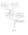
- FIG. 3 An example of the confidence level determination performed by the quality measurement circuit 200 is illustrated in FIG. 3 .
- the input images F 1 -F N include a pair of a left-view image IMG_L and a right-view image IMG _ R.
- the comparison unit 202 is therefore operative to check the percentage of perfect matched regions found in the left-view image IMG_L and the right-view image IMG_R by comparing pixel values of the left-view image and the right-view image, and then generate the comparison result CR indicative of the percentage of perfect matched regions.
- the percentage of perfect matched regions is low, this implies that there is a large occlusion region or there are many occlusion regions or unmatched regions. That is, the disparity/depth estimation is unreliable.
- the quality estimation unit 204 refers to the percentage of perfect matched regions (i.e., the comparison result CR) to set the confidence level CL.
- the confidence level CL may be positively correlated with the percentage of perfect matched regions. In other words, the confidence level CL would be set by a larger value when the percentage of perfect matched regions is higher, and the confidence level CL would be set by a smaller value when the percentage of perfect matched regions is lower.
- FIG. 4 is a block diagram illustrating a second exemplary implementation of a quality measurement circuit according to the present invention.
- the quality measurement circuit 104 shown in FIG. 1 may be realized by the quality measurement circuit 400 shown in FIG. 4 .
- the quality measurement circuit 400 includes a reconstruction unit 402, a comparison unit 404 and a quality estimation unit 406.
- the reconstruction unit 402 is arranged for generating at least one reconstructed image FR 1 -FR N according to at least one depth-related information map MAP 1 -MAP N and at least one image selected from the input images F 1 -F N .
- the comparison unit 404 is coupled to the reconstruction unit 402, and arranged for performing a comparison upon at least one reconstructed image FR 1 -FR N and at least one image selected from the input images F 1 -F N , and accordingly generating a comparison result CR'.
- the quality estimation unit 406 is coupled to the comparison unit 404, and arranged for estimating the confidence level CL by referring to the comparison result CR'.
- FIG. 5 An example of the confidence level determination performed by the quality measurement circuit 400 is illustrated in FIG. 5 .
- the input images F 1 -F N include a pair of a left-view image IMG_L and a right-view image IMG_R, where one of the input images IMG_1 and IMG_2 shown in FIG. 5 is the left-view image IMG_L, and the other of the input images IMG_1 and IMG_2 shown in FIG. 5 is the right-view image IMG_R.
- the reconstruction unit 402 When the input image IMG_1 is the left-view image IMG_L, the reconstruction unit 402 generates a reconstructed image IMG_2' (e.g., a reconstructed right-view image IMG_R') according to the left-view image IMG_L and the corresponding disparity/depth map MAP_L of the left-view image IMG_L, and the comparison unit 404 checks the percentage of well reconstructed regions found in the original input image IMG_2 (i.e., the right-view image IMG_R) and the reconstructed image IMG_2' (i.e., the reconstructed right-view image IMG_R') by comparing pixel values of the original right-view image and the reconstructed right-view image, and generates the comparison result CR' indicative of the percentage of well reconstructed regions.
- a reconstructed image IMG_2' e.g., a reconstructed right-view image IMG_R'
- the comparison unit 404 checks
- the quality estimation unit 406 refers to the percentage of well reconstructed regions (i.e., the comparison result CR') to set the confidence level CL.
- the confidence level CL may be positively correlated with the percentage of well reconstructed regions. In other words, the confidence level CL would be set by a larger value when the percentage of well reconstructed regions is higher, and the confidence level CL would be set by a smaller value when the percentage of well reconstructed regions is lower.
- the reconstruction unit 402 When the input image IMG_1 is the right-view image IMG_R, the reconstruction unit 402 generates a reconstructed image IMG_2' (e.g., a reconstructed left-view image IMG_L') according to the right-view image IMG_R and the disparity/depth map MAP_R of the right-view image IMG_R, and the comparison unit 404 checks the percentage of well reconstructed regions found in the original input image IMG_2 (i.e., the left-view image IMG_L) and the reconstructed image IMG_2' (i.e., the reconstructed left-view image IMG_L') by comparing pixel values of the original right-view image and the reconstructed right-view image, and generates the comparison result CR' indicative of the percentage of well reconstructed regions.
- the quality estimation unit 406 refers to the percentage of well reconstructed regions (i.e., the comparison result CR') to set the confidence level CL. The same objective of
- the adjustment circuit 106 After receiving the confidence level CL provided by the quality measurement circuit, the adjustment circuit 106 refers to the received confidence level CL to apply adaptive depth adjustment to the depth-related information maps MAP 1 -MAP N for achieving the objective of making adaptive depth control to the input images F 1 -F N to be displayed.
- FIG. 6 is a diagram illustrating a first exemplary implementation of an adjustment circuit according to the present invention.
- the adjustment circuit 106 shown in FIG. 1 may be realized by the adjustment circuit 600 shown in FIG. 6 .
- the adjustment circuit 600 includes an adjustment value determination unit 602 and an adjustment unit 604, where the adjustment value determination unit 112 and the adjustment unit 114 shown in FIG. 1 may be realized by the adjustment value determination unit 602 and the adjustment unit 604, respectively.
- the adjustment value determination unit 602 includes a depth controller 606 and an adjustment value determinator 608.
- the depth controller 606 is arranged for setting a plurality of depth control weighting factors W D1- WD N for different depth-related information maps (e.g., disparity maps or depth maps) MAP 1 -MAP N in response to the confidence level CL.
- the depth control weighting factors W D1 -W DN may be identical to each other. That is, the depth controller 606 may use the same value to set the depth control weighting factors W D1 -W DN. In another exemplary design, some or all of the depth control weighting factors W D1 -W DN may be different from each other.
- the depth controller 606 may set values of the depth control weighting factors W D1 -W DN , individually.
- the depth control weighting factor may be positively correlated with the confidence level CL. For example, the depth control weighting factor would be set by a larger value when the confidence level CL is higher, and the depth control weighting factor would be set by a smaller value when the confidence level CL is lower.
- the adjustment value determinator 608 is coupled to the depth controller 606, and includes a plurality of multipliers 609_1-609_N.
- the multipliers 609_1-609_N receive the depth control weighting factors W D1 -W DN , respectively.
- Each multiplier is arranged for multiplying a corresponding depth control weighting factor and each depth-related value (e.g., a disparity value or a depth value) included in a corresponding depth-related information map.
- the adjustment value determinator 608 is a pixel-based processing circuit used to determine an adjustment value for each depth-related value.
- the adjustment unit 604 is coupled to the adjustment value determinator 608, and includes a plurality of adders 605_1-605_N, each arranged for perform a subtraction operation upon adjustment values and respective depth-related values of one depth-related information map to thereby generate one adjusted depth-related information map having adjusted depth-related values included therein.
- the adjustment unit 604 outputs the adjusted depth-related information maps MAP 1 '-MAP N ' with the desired disparity/depth setting.
- the following image interpolation unit 101 can refer to the adjusted depth-related information maps MAP 1 '-MAP N ' to perform depth control upon the input images F 1 -F N and accordingly generate the output images F 1 '-F N ' with an adjusted depth effect.
- the pixel-based operation of the adjustment circuit 600 may be expressed using the following equation.
- D Adjusted D Estimated - ⁇ ⁇ D Estimated
- D Adjusted represents the adjusted disparity/depth value included in an adjusted disparity/depth map
- D Estimated represents the original disparity/depth value included in an estimated disparity/depth map
- ⁇ ⁇ D Estimated represents the adjustment value
- ⁇ represent the depth control weighting factor. It should be noted that the same depth control weighting factor is applied to all of the disparity/depth values included in the same estimated disparity/depth map.
- the depth control weighting factor would be reduced to mitigate the undesired side effect, thus allowing the 3D display to be adjusted to a comfortable convergence depth. In this way, the 3D display quality is improved.
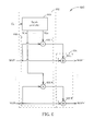
- FIG. 7 is a diagram illustrating a second exemplary implementation of an adjustment circuit according to the present invention.
- the adjustment circuit 106 shown in FIG. 1 may be realized by the adjustment circuit 700 shown in FIG. 7 .
- the adjustment circuit 700 includes an adjustment value determination unit 702 and an adjustment unit 704, where the adjustment value determination unit 112 and the adjustment unit 114 shown in FIG. 1 may be realized by the adjustment value determination unit 702 and the adjustment unit 704, respectively.
- the adjustment value determination unit 702 includes a depth controller 706, an adjustment value determinator 708, a plurality of global depth-related value extractors 711_1-711_N, and a plurality of local depth-related value extractors 712_1-712_N.
- the depth controller 706 is arranged for setting a plurality of first depth control weighting factors W G1 -W GN for different depth-related information maps (e.g., disparity maps or depth maps) MAP 1 -MAP N and further arranged for setting a plurality of second depth control weighting factors W L1 -W LN for different depth-related information maps (e.g., disparity maps or depth maps) MAP 1 -MAP N .
- the second depth control weighting factors W L1 -W LN may be dynamically set in response to the confidence level CL, and first depth control weighting factors W G1 -W GN may be kept unchanged each time determination of the adjustment value for each depth-related value is performed.
- the first depth control weighting factors W G1 -W GN and the second depth control weighting factors W L1 -W LN may be adjusted separately.
- the depth control weighting factor may be positively correlated with the confidence level CL.
- the depth control weighting factor would be set by a larger value when the confidence level CL is higher, and the depth control weighting factor would be set by a smaller value when the confidence level CL is lower.
- the confidence level and the second depth control weighting factor e.g., a local weighting factor
- first depth control weighting factors W W1 -W WN may be identical to or different from each other, and/or the second depth control weighting factors W L1 -W LN may be identical to or different from each other, depending upon actual design requirement/consideration.
- Each of the global depth-related value extractors 711_1-711_N is arranged for determining a global depth-related value (e.g., a global disparity/depth value) according to all depth-related values included in a corresponding depth-related information map.
- a global depth-related value e.g., a global disparity/depth value
- each of the depth-related information maps MAP 1 -MAP N would have one global depth-related value only. Therefore, the global depth-related value extractors 711_1-711_N generate global depth-related values D G1 -D GN , respectively.
- Each of the local depth-related value extractors 712_1-712_N is arranged for determining a local depth-related value (e.g., a local disparity/depth value) for each depth-related value included in a corresponding depth-related information map according to the global depth-related value derived from the corresponding depth-related information map.
- a local depth-related value e.g., a local disparity/depth value
- each of the depth-related information maps MAP 1 -MAP N would have N local depth-related values if the number of depth-related values included in a depth-related information map is equal to N.
- each global depth-related value extractor sets the global depth-related value by an average D AVG of all depth-related values included in a corresponding depth-related information map.
- D i is the i th depth-related value included in an estimated depth-related information map (e.g., one of MAP 1 -MAP N ), and N is the number of depth-related values included in the estimated depth-related information map (e.g., one of MAP 1 -MAP N ).
- each global depth-related value extractor sets the global depth-related value by a weighted sum Dws of all depth-related values included in a corresponding depth-related information map, where a weighting factor of a first depth-related value is different from a weighting factor of a second depth-related value when the first depth-related value is different from the second depth-related value.
- each local depth-related value extractor in this embodiment may set the local depth-related value for each depth-related value included in the corresponding depth-related information map by subtracting the global depth-related value (e.g., D AVG or D SW ) from the depth-related value, as shown in FIG. 9 .
- the global depth-related value e.g., D AVG or D SW
- the adjustment value determinator 708 is coupled to the global depth-related value extractors 711_1-711_N and local depth-related value extractors 712_1-712_N, and includes a plurality of first multipliers 709_1-709_N, a plurality of second multipliers 710_1-710_N, and a plurality of adders 713_1-713_N.
- Each of the first multipliers 709_1-709_N is arranged for multiplying a corresponding first depth control weighting factor W G1 -W GN and each global depth-related value (e.g., D AVG or D SW ).
- Each of the second multipliers 710_1-710_N is arranged for multiplying a corresponding second depth control weighting factor W L1 -W LN and the local depth-related values.
- Each of the adders 713_1-713_N performs an addition operation upon outputs of a preceding first multiplier and a preceding second multiplier to determine an adjustment value for a corresponding depth-related information map.
- the adjustment value determinator 708 in this embodiment is used to determine an adjustment value for each depth-related value.
- the adjustment unit 704 it is coupled to the adjustment value determinator 708, and includes a plurality of adders 705_1-705_N, each arranged for performing a subtraction operation upon adjustment values and respective depth-related values to generate one adjusted depth-related information map having adjusted depth-related values included therein. In this way, the adjustment unit 704 outputs the adjusted depth-related information maps MAP 1 '-MAP N ' with the desired disparity/depth setting.
- the pixel-based operation of the adjustment circuit 700 may be expressed using the following equation.
- D Adjusted D Estimated - ⁇ ⁇ D Local - ⁇ ⁇ D Global
- D Adjusted represents an adjusted disparity/depth value included in an adjusted disparity/depth map
- D Estimated represents an original disparity/depth value included in an estimated disparity/depth map
- ⁇ D estimated represents a local part of an adjustment value
- ⁇ D global represents a global part of the adjustment value
- ⁇ represent a second depth control weighting factor
- ⁇ represents a first depth control weighting factor
- the same second depth control weighting factor i.e., the same local depth control weighting factor
- the first depth control weighting factor i.e., the global depth control weighting factor
- the second depth control weighting factor would be reduced to mitigate the undesired side effect, thus allowing the 3D display to be adjusted to a comfortable convergence depth. In this way, the 3D display quality is improved.
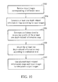
- FIG. 10 is a flowchart illustrating a depth control method according to an embodiment of the present invention. If the result is substantially the same, the depth control method is not required to be executed in the exact order shown in FIG. 10 .
- the exemplary depth control method may be employed by the device shown in FIG. 1 , and may be briefly summarized by following steps.
- Steps 1002 and 1004 may be executed by the aforementioned depth-related information map generation circuit 102
- step 1006 may be executed by the aforementioned quality measurement circuit 104
- step 1008 may be executed by the aforementioned adjustment circuit 106
- step 1010 may be executed by the aforementioned image interpolation unit 101.
- the depth control apparatus 100 employs a hardware-based solution to implement the adaptive depth adjustment feature.
- a software-based solution may be employed to implement the adaptive depth adjustment feature.
- FIG. 11 is a block diagram illustrating a depth control apparatus according to a second embodiment of the present invention.
- the depth control apparatus 1100 includes a processor (e.g., a micro control unit or a central processing unit) 1102 and a machine readable medium (e.g., a non-volatile memory) 1104.
- the machine readable medium 1104 is coupled to the processor 1102, and used to store a program code PROG such as firmware of the depth control apparatus 1100.
- the program code PROG causes the processor 1102 to perform steps shown in FIG. 10 .
- the same objective of implementing the adaptive depth adjustment is achieved.
Landscapes
- Engineering & Computer Science (AREA)
- Theoretical Computer Science (AREA)
- Computer Vision & Pattern Recognition (AREA)
- Physics & Mathematics (AREA)
- General Physics & Mathematics (AREA)
- Signal Processing (AREA)
- Multimedia (AREA)
- Quality & Reliability (AREA)
- Testing, Inspecting, Measuring Of Stereoscopic Televisions And Televisions (AREA)
- Image Processing (AREA)
- Investigating Or Analyzing Materials By The Use Of Ultrasonic Waves (AREA)
- Analysing Materials By The Use Of Radiation (AREA)
- Ultra Sonic Daignosis Equipment (AREA)
Applications Claiming Priority (2)
| Application Number | Priority Date | Filing Date | Title |
|---|---|---|---|
| US201161579669P | 2011-12-23 | 2011-12-23 | |
| US13/570,256 US20130162763A1 (en) | 2011-12-23 | 2012-08-09 | Method and apparatus for adjusting depth-related information map according to quality measurement result of the depth-related information map |
Publications (3)
| Publication Number | Publication Date |
|---|---|
| EP2608549A2 true EP2608549A2 (de) | 2013-06-26 |
| EP2608549A3 EP2608549A3 (de) | 2015-06-03 |
| EP2608549B1 EP2608549B1 (de) | 2017-09-06 |
Family
ID=47602716
Family Applications (1)
| Application Number | Title | Priority Date | Filing Date |
|---|---|---|---|
| EP12008266.4A Active EP2608549B1 (de) | 2011-12-23 | 2012-12-11 | Verfahren und Vorrichtung zur Einstellung einer tiefenbezogenen Informationskarte entsprechend dem Qualitätsmessergebnis der tiefenbezogenen Informationskarte |
Country Status (3)
| Country | Link |
|---|---|
| US (1) | US20130162763A1 (de) |
| EP (1) | EP2608549B1 (de) |
| CN (1) | CN103179414B (de) |
Cited By (2)
| Publication number | Priority date | Publication date | Assignee | Title |
|---|---|---|---|---|
| CN104318525A (zh) * | 2014-10-17 | 2015-01-28 | 合肥工业大学 | 基于空间引导滤波的图像细节增强方法 |
| US20170295355A1 (en) * | 2014-10-27 | 2017-10-12 | Canon Kabushiki Kaisha | Data processing apparatus, imaging apparatus and data processing method |
Families Citing this family (8)
| Publication number | Priority date | Publication date | Assignee | Title |
|---|---|---|---|---|
| JP2013172190A (ja) * | 2012-02-17 | 2013-09-02 | Sony Corp | 画像処理装置、および画像処理方法、並びにプログラム |
| EP2860975A1 (de) * | 2013-10-09 | 2015-04-15 | Thomson Licensing | Verfahren zur Verarbeitung von mindestens einer Disparitätskarte, zugehörige elektronische Vorrichtung und Computerprogrammprodukt |
| TWI636427B (zh) * | 2017-05-31 | 2018-09-21 | 鈺立微電子股份有限公司 | 對應影像擷取裝置的深度圖品質的驗證方法及其驗證系統 |
| CN110852134A (zh) * | 2018-07-27 | 2020-02-28 | 北京市商汤科技开发有限公司 | 活体检测方法、装置及系统、电子设备和存储介质 |
| FR3088510A1 (fr) * | 2018-11-09 | 2020-05-15 | Orange | Synthese de vues |
| US20200186776A1 (en) * | 2018-11-14 | 2020-06-11 | Htc Corporation | Image processing system and image processing method |
| JP2023172202A (ja) * | 2022-05-23 | 2023-12-06 | キヤノン株式会社 | 画像処理装置、移動体、画像処理方法及びコンピュータプログラム |
| US20240210274A1 (en) * | 2022-12-22 | 2024-06-27 | Meta Platforms Technologies, Llc | Optical combiners for binocular disparity detection |
Family Cites Families (8)
| Publication number | Priority date | Publication date | Assignee | Title |
|---|---|---|---|---|
| US5917937A (en) * | 1997-04-15 | 1999-06-29 | Microsoft Corporation | Method for performing stereo matching to recover depths, colors and opacities of surface elements |
| JP5387377B2 (ja) * | 2009-12-14 | 2014-01-15 | ソニー株式会社 | 画像処理装置、および画像処理方法、並びにプログラム |
| KR101637491B1 (ko) * | 2009-12-30 | 2016-07-08 | 삼성전자주식회사 | 3차원 영상 데이터 생성 방법 및 장치 |
| JP5387856B2 (ja) * | 2010-02-16 | 2014-01-15 | ソニー株式会社 | 画像処理装置、画像処理方法、画像処理プログラムおよび撮像装置 |
| US9142026B2 (en) * | 2010-02-26 | 2015-09-22 | Thomson Licensing | Confidence map, method for generating the same and method for refining a disparity map |
| US8428342B2 (en) * | 2010-08-12 | 2013-04-23 | At&T Intellectual Property I, L.P. | Apparatus and method for providing three dimensional media content |
| CN102098526B (zh) * | 2011-01-28 | 2012-08-22 | 清华大学 | 一种深度图求取方法及装置 |
| US20130095920A1 (en) * | 2011-10-13 | 2013-04-18 | Microsoft Corporation | Generating free viewpoint video using stereo imaging |
-
2012
- 2012-08-09 US US13/570,256 patent/US20130162763A1/en not_active Abandoned
- 2012-12-10 CN CN201210530284.6A patent/CN103179414B/zh active Active
- 2012-12-11 EP EP12008266.4A patent/EP2608549B1/de active Active
Non-Patent Citations (1)
| Title |
|---|
| None |
Cited By (6)
| Publication number | Priority date | Publication date | Assignee | Title |
|---|---|---|---|---|
| CN104318525A (zh) * | 2014-10-17 | 2015-01-28 | 合肥工业大学 | 基于空间引导滤波的图像细节增强方法 |
| CN104318525B (zh) * | 2014-10-17 | 2017-02-15 | 合肥工业大学 | 基于空间引导滤波的图像细节增强方法 |
| US20170295355A1 (en) * | 2014-10-27 | 2017-10-12 | Canon Kabushiki Kaisha | Data processing apparatus, imaging apparatus and data processing method |
| EP3213290A4 (de) * | 2014-10-27 | 2018-07-04 | Canon Kabushiki Kaisha | Datenverarbeitungsvorrichtung, abbildungsvorrichtung und datenverarbeitungsverfahren |
| US10547824B2 (en) | 2014-10-27 | 2020-01-28 | Canon Kabushiki Kaisha | Data processing apparatus, imaging apparatus and data processing method |
| US11044453B2 (en) | 2014-10-27 | 2021-06-22 | Canon Kabushiki Kaisha | Data processing apparatus, imaging apparatus and data processing method |
Also Published As
| Publication number | Publication date |
|---|---|
| CN103179414A (zh) | 2013-06-26 |
| CN103179414B (zh) | 2015-08-19 |
| US20130162763A1 (en) | 2013-06-27 |
| EP2608549A3 (de) | 2015-06-03 |
| EP2608549B1 (de) | 2017-09-06 |
Similar Documents
| Publication | Publication Date | Title |
|---|---|---|
| EP2608549B1 (de) | Verfahren und Vorrichtung zur Einstellung einer tiefenbezogenen Informationskarte entsprechend dem Qualitätsmessergebnis der tiefenbezogenen Informationskarte | |
| US8116557B2 (en) | 3D image processing apparatus and method | |
| Song et al. | MCL-3D: A database for stereoscopic image quality assessment using 2D-image-plus-depth source | |
| US8817073B2 (en) | System and method of processing 3D stereoscopic image | |
| US8798160B2 (en) | Method and apparatus for adjusting parallax in three-dimensional video | |
| JP5387377B2 (ja) | 画像処理装置、および画像処理方法、並びにプログラム | |
| KR101502362B1 (ko) | 영상처리 장치 및 방법 | |
| US10115207B2 (en) | Stereoscopic image processing method and apparatus thereof | |
| Rahaman et al. | Virtual view synthesis for free viewpoint video and multiview video compression using Gaussian mixture modelling | |
| US20130051659A1 (en) | Stereoscopic image processing device and stereoscopic image processing method | |
| TW201242335A (en) | Image processing device, image processing method, and program | |
| KR20120049997A (ko) | 영상 변환 장치 및 이를 이용하는 디스플레이 장치와 그 방법들 | |
| CN104601979A (zh) | 多视点图像显示设备及其控制方法 | |
| KR20130125777A (ko) | 적응 시차를 갖는 3d 디스플레이를 위한 방법 및 시스템 | |
| US20120236114A1 (en) | Depth information generator for generating depth information output by only processing part of received images having different views, and related depth information generating method and depth adjusting apparatus thereof | |
| WO2023235273A1 (en) | Layered view synthesis system and method | |
| Tam et al. | Stereoscopic image rendering based on depth maps created from blur and edge information | |
| US20120044244A1 (en) | Method for Image Processing and an Apparatus Thereof | |
| US9210396B2 (en) | Stereoscopic image generation apparatus and stereoscopic image generation method | |
| US9838672B2 (en) | Apparatus and method for referring to motion status of image capture device to generate stereo image pair to auto-stereoscopic display for stereo preview | |
| JP5931062B2 (ja) | 立体画像処理装置、立体画像処理方法、及びプログラム | |
| KR20160114983A (ko) | 영상 변환 장치 및 방법 | |
| KR20080000149A (ko) | 다시점화상의 처리 방법 및 장치 | |
| US20140063206A1 (en) | System and method of viewer centric depth adjustment | |
| KR100914171B1 (ko) | 휴대 방송에서의 3차원 서비스를 위한 깊이 영상 기반렌더링 장치 및 방법 |
Legal Events
| Date | Code | Title | Description |
|---|---|---|---|
| AK | Designated contracting states |
Kind code of ref document: A2 Designated state(s): AL AT BE BG CH CY CZ DE DK EE ES FI FR GB GR HR HU IE IS IT LI LT LU LV MC MK MT NL NO PL PT RO RS SE SI SK SM TR |
|
| AX | Request for extension of the european patent |
Extension state: BA ME |
|
| PUAI | Public reference made under article 153(3) epc to a published international application that has entered the european phase |
Free format text: ORIGINAL CODE: 0009012 |
|
| PUAL | Search report despatched |
Free format text: ORIGINAL CODE: 0009013 |
|
| AK | Designated contracting states |
Kind code of ref document: A3 Designated state(s): AL AT BE BG CH CY CZ DE DK EE ES FI FR GB GR HR HU IE IS IT LI LT LU LV MC MK MT NL NO PL PT RO RS SE SI SK SM TR |
|
| AX | Request for extension of the european patent |
Extension state: BA ME |
|
| RIC1 | Information provided on ipc code assigned before grant |
Ipc: H04N 13/00 20060101AFI20150429BHEP Ipc: G06T 7/00 20060101ALI20150429BHEP |
|
| 17P | Request for examination filed |
Effective date: 20151202 |
|
| RBV | Designated contracting states (corrected) |
Designated state(s): AL AT BE BG CH CY CZ DE DK EE ES FI FR GB GR HR HU IE IS IT LI LT LU LV MC MK MT NL NO PL PT RO RS SE SI SK SM TR |
|
| 17Q | First examination report despatched |
Effective date: 20160819 |
|
| STAA | Information on the status of an ep patent application or granted ep patent |
Free format text: STATUS: EXAMINATION IS IN PROGRESS |
|
| GRAP | Despatch of communication of intention to grant a patent |
Free format text: ORIGINAL CODE: EPIDOSNIGR1 |
|
| STAA | Information on the status of an ep patent application or granted ep patent |
Free format text: STATUS: GRANT OF PATENT IS INTENDED |
|
| RIC1 | Information provided on ipc code assigned before grant |
Ipc: H04N 13/00 20060101AFI20170428BHEP Ipc: G06T 7/593 20170101ALI20170428BHEP Ipc: G06T 7/00 20170101ALI20170428BHEP |
|
| INTG | Intention to grant announced |
Effective date: 20170529 |
|
| GRAS | Grant fee paid |
Free format text: ORIGINAL CODE: EPIDOSNIGR3 |
|
| GRAA | (expected) grant |
Free format text: ORIGINAL CODE: 0009210 |
|
| STAA | Information on the status of an ep patent application or granted ep patent |
Free format text: STATUS: THE PATENT HAS BEEN GRANTED |
|
| AK | Designated contracting states |
Kind code of ref document: B1 Designated state(s): AL AT BE BG CH CY CZ DE DK EE ES FI FR GB GR HR HU IE IS IT LI LT LU LV MC MK MT NL NO PL PT RO RS SE SI SK SM TR |
|
| REG | Reference to a national code |
Ref country code: GB Ref legal event code: FG4D |
|
| REG | Reference to a national code |
Ref country code: CH Ref legal event code: EP Ref country code: AT Ref legal event code: REF Ref document number: 927060 Country of ref document: AT Kind code of ref document: T Effective date: 20170915 |
|
| REG | Reference to a national code |
Ref country code: IE Ref legal event code: FG4D |
|
| REG | Reference to a national code |
Ref country code: DE Ref legal event code: R096 Ref document number: 602012036821 Country of ref document: DE |
|
| REG | Reference to a national code |
Ref country code: FR Ref legal event code: PLFP Year of fee payment: 6 |
|
| REG | Reference to a national code |
Ref country code: NL Ref legal event code: MP Effective date: 20170906 |
|
| REG | Reference to a national code |
Ref country code: LT Ref legal event code: MG4D |
|
| PG25 | Lapsed in a contracting state [announced via postgrant information from national office to epo] |
Ref country code: SE Free format text: LAPSE BECAUSE OF FAILURE TO SUBMIT A TRANSLATION OF THE DESCRIPTION OR TO PAY THE FEE WITHIN THE PRESCRIBED TIME-LIMIT Effective date: 20170906 Ref country code: FI Free format text: LAPSE BECAUSE OF FAILURE TO SUBMIT A TRANSLATION OF THE DESCRIPTION OR TO PAY THE FEE WITHIN THE PRESCRIBED TIME-LIMIT Effective date: 20170906 Ref country code: NO Free format text: LAPSE BECAUSE OF FAILURE TO SUBMIT A TRANSLATION OF THE DESCRIPTION OR TO PAY THE FEE WITHIN THE PRESCRIBED TIME-LIMIT Effective date: 20171206 Ref country code: LT Free format text: LAPSE BECAUSE OF FAILURE TO SUBMIT A TRANSLATION OF THE DESCRIPTION OR TO PAY THE FEE WITHIN THE PRESCRIBED TIME-LIMIT Effective date: 20170906 Ref country code: HR Free format text: LAPSE BECAUSE OF FAILURE TO SUBMIT A TRANSLATION OF THE DESCRIPTION OR TO PAY THE FEE WITHIN THE PRESCRIBED TIME-LIMIT Effective date: 20170906 |
|
| REG | Reference to a national code |
Ref country code: AT Ref legal event code: MK05 Ref document number: 927060 Country of ref document: AT Kind code of ref document: T Effective date: 20170906 |
|
| PG25 | Lapsed in a contracting state [announced via postgrant information from national office to epo] |
Ref country code: RS Free format text: LAPSE BECAUSE OF FAILURE TO SUBMIT A TRANSLATION OF THE DESCRIPTION OR TO PAY THE FEE WITHIN THE PRESCRIBED TIME-LIMIT Effective date: 20170906 Ref country code: GR Free format text: LAPSE BECAUSE OF FAILURE TO SUBMIT A TRANSLATION OF THE DESCRIPTION OR TO PAY THE FEE WITHIN THE PRESCRIBED TIME-LIMIT Effective date: 20171207 Ref country code: LV Free format text: LAPSE BECAUSE OF FAILURE TO SUBMIT A TRANSLATION OF THE DESCRIPTION OR TO PAY THE FEE WITHIN THE PRESCRIBED TIME-LIMIT Effective date: 20170906 Ref country code: BG Free format text: LAPSE BECAUSE OF FAILURE TO SUBMIT A TRANSLATION OF THE DESCRIPTION OR TO PAY THE FEE WITHIN THE PRESCRIBED TIME-LIMIT Effective date: 20171206 Ref country code: ES Free format text: LAPSE BECAUSE OF FAILURE TO SUBMIT A TRANSLATION OF THE DESCRIPTION OR TO PAY THE FEE WITHIN THE PRESCRIBED TIME-LIMIT Effective date: 20170906 |
|
| PG25 | Lapsed in a contracting state [announced via postgrant information from national office to epo] |
Ref country code: NL Free format text: LAPSE BECAUSE OF FAILURE TO SUBMIT A TRANSLATION OF THE DESCRIPTION OR TO PAY THE FEE WITHIN THE PRESCRIBED TIME-LIMIT Effective date: 20170906 |
|
| PG25 | Lapsed in a contracting state [announced via postgrant information from national office to epo] |
Ref country code: RO Free format text: LAPSE BECAUSE OF FAILURE TO SUBMIT A TRANSLATION OF THE DESCRIPTION OR TO PAY THE FEE WITHIN THE PRESCRIBED TIME-LIMIT Effective date: 20170906 Ref country code: PL Free format text: LAPSE BECAUSE OF FAILURE TO SUBMIT A TRANSLATION OF THE DESCRIPTION OR TO PAY THE FEE WITHIN THE PRESCRIBED TIME-LIMIT Effective date: 20170906 Ref country code: CZ Free format text: LAPSE BECAUSE OF FAILURE TO SUBMIT A TRANSLATION OF THE DESCRIPTION OR TO PAY THE FEE WITHIN THE PRESCRIBED TIME-LIMIT Effective date: 20170906 |
|
| PG25 | Lapsed in a contracting state [announced via postgrant information from national office to epo] |
Ref country code: AT Free format text: LAPSE BECAUSE OF FAILURE TO SUBMIT A TRANSLATION OF THE DESCRIPTION OR TO PAY THE FEE WITHIN THE PRESCRIBED TIME-LIMIT Effective date: 20170906 Ref country code: SM Free format text: LAPSE BECAUSE OF FAILURE TO SUBMIT A TRANSLATION OF THE DESCRIPTION OR TO PAY THE FEE WITHIN THE PRESCRIBED TIME-LIMIT Effective date: 20170906 Ref country code: IT Free format text: LAPSE BECAUSE OF FAILURE TO SUBMIT A TRANSLATION OF THE DESCRIPTION OR TO PAY THE FEE WITHIN THE PRESCRIBED TIME-LIMIT Effective date: 20170906 Ref country code: SK Free format text: LAPSE BECAUSE OF FAILURE TO SUBMIT A TRANSLATION OF THE DESCRIPTION OR TO PAY THE FEE WITHIN THE PRESCRIBED TIME-LIMIT Effective date: 20170906 Ref country code: IS Free format text: LAPSE BECAUSE OF FAILURE TO SUBMIT A TRANSLATION OF THE DESCRIPTION OR TO PAY THE FEE WITHIN THE PRESCRIBED TIME-LIMIT Effective date: 20180106 Ref country code: EE Free format text: LAPSE BECAUSE OF FAILURE TO SUBMIT A TRANSLATION OF THE DESCRIPTION OR TO PAY THE FEE WITHIN THE PRESCRIBED TIME-LIMIT Effective date: 20170906 |
|
| REG | Reference to a national code |
Ref country code: DE Ref legal event code: R097 Ref document number: 602012036821 Country of ref document: DE |
|
| PLBE | No opposition filed within time limit |
Free format text: ORIGINAL CODE: 0009261 |
|
| STAA | Information on the status of an ep patent application or granted ep patent |
Free format text: STATUS: NO OPPOSITION FILED WITHIN TIME LIMIT |
|
| PG25 | Lapsed in a contracting state [announced via postgrant information from national office to epo] |
Ref country code: DK Free format text: LAPSE BECAUSE OF FAILURE TO SUBMIT A TRANSLATION OF THE DESCRIPTION OR TO PAY THE FEE WITHIN THE PRESCRIBED TIME-LIMIT Effective date: 20170906 |
|
| REG | Reference to a national code |
Ref country code: CH Ref legal event code: PL |
|
| 26N | No opposition filed |
Effective date: 20180607 |
|
| PG25 | Lapsed in a contracting state [announced via postgrant information from national office to epo] |
Ref country code: SI Free format text: LAPSE BECAUSE OF FAILURE TO SUBMIT A TRANSLATION OF THE DESCRIPTION OR TO PAY THE FEE WITHIN THE PRESCRIBED TIME-LIMIT Effective date: 20170906 |
|
| REG | Reference to a national code |
Ref country code: IE Ref legal event code: MM4A |
|
| PG25 | Lapsed in a contracting state [announced via postgrant information from national office to epo] |
Ref country code: LU Free format text: LAPSE BECAUSE OF NON-PAYMENT OF DUE FEES Effective date: 20171211 Ref country code: MT Free format text: LAPSE BECAUSE OF NON-PAYMENT OF DUE FEES Effective date: 20171211 |
|
| REG | Reference to a national code |
Ref country code: BE Ref legal event code: MM Effective date: 20171231 |
|
| PG25 | Lapsed in a contracting state [announced via postgrant information from national office to epo] |
Ref country code: IE Free format text: LAPSE BECAUSE OF NON-PAYMENT OF DUE FEES Effective date: 20171211 |
|
| PG25 | Lapsed in a contracting state [announced via postgrant information from national office to epo] |
Ref country code: BE Free format text: LAPSE BECAUSE OF NON-PAYMENT OF DUE FEES Effective date: 20171231 Ref country code: LI Free format text: LAPSE BECAUSE OF NON-PAYMENT OF DUE FEES Effective date: 20171231 Ref country code: CH Free format text: LAPSE BECAUSE OF NON-PAYMENT OF DUE FEES Effective date: 20171231 |
|
| PG25 | Lapsed in a contracting state [announced via postgrant information from national office to epo] |
Ref country code: HU Free format text: LAPSE BECAUSE OF FAILURE TO SUBMIT A TRANSLATION OF THE DESCRIPTION OR TO PAY THE FEE WITHIN THE PRESCRIBED TIME-LIMIT; INVALID AB INITIO Effective date: 20121211 Ref country code: MC Free format text: LAPSE BECAUSE OF FAILURE TO SUBMIT A TRANSLATION OF THE DESCRIPTION OR TO PAY THE FEE WITHIN THE PRESCRIBED TIME-LIMIT Effective date: 20170906 |
|
| PG25 | Lapsed in a contracting state [announced via postgrant information from national office to epo] |
Ref country code: CY Free format text: LAPSE BECAUSE OF NON-PAYMENT OF DUE FEES Effective date: 20170906 |
|
| PG25 | Lapsed in a contracting state [announced via postgrant information from national office to epo] |
Ref country code: MK Free format text: LAPSE BECAUSE OF FAILURE TO SUBMIT A TRANSLATION OF THE DESCRIPTION OR TO PAY THE FEE WITHIN THE PRESCRIBED TIME-LIMIT Effective date: 20170906 |
|
| PG25 | Lapsed in a contracting state [announced via postgrant information from national office to epo] |
Ref country code: TR Free format text: LAPSE BECAUSE OF FAILURE TO SUBMIT A TRANSLATION OF THE DESCRIPTION OR TO PAY THE FEE WITHIN THE PRESCRIBED TIME-LIMIT Effective date: 20170906 |
|
| PG25 | Lapsed in a contracting state [announced via postgrant information from national office to epo] |
Ref country code: PT Free format text: LAPSE BECAUSE OF FAILURE TO SUBMIT A TRANSLATION OF THE DESCRIPTION OR TO PAY THE FEE WITHIN THE PRESCRIBED TIME-LIMIT Effective date: 20170906 |
|
| PG25 | Lapsed in a contracting state [announced via postgrant information from national office to epo] |
Ref country code: AL Free format text: LAPSE BECAUSE OF FAILURE TO SUBMIT A TRANSLATION OF THE DESCRIPTION OR TO PAY THE FEE WITHIN THE PRESCRIBED TIME-LIMIT Effective date: 20170906 |
|
| P01 | Opt-out of the competence of the unified patent court (upc) registered |
Effective date: 20230607 |
|
| PGFP | Annual fee paid to national office [announced via postgrant information from national office to epo] |
Ref country code: FR Payment date: 20250930 Year of fee payment: 14 |
|
| PGFP | Annual fee paid to national office [announced via postgrant information from national office to epo] |
Ref country code: DE Payment date: 20250930 Year of fee payment: 14 |
|
| PGFP | Annual fee paid to national office [announced via postgrant information from national office to epo] |
Ref country code: GB Payment date: 20251001 Year of fee payment: 14 |