EP2608358A1 - Flywheel power generating facility and operating method therefor - Google Patents
Flywheel power generating facility and operating method therefor Download PDFInfo
- Publication number
- EP2608358A1 EP2608358A1 EP12830877.2A EP12830877A EP2608358A1 EP 2608358 A1 EP2608358 A1 EP 2608358A1 EP 12830877 A EP12830877 A EP 12830877A EP 2608358 A1 EP2608358 A1 EP 2608358A1
- Authority
- EP
- European Patent Office
- Prior art keywords
- flywheel
- driving motor
- electric power
- facility
- power
- Prior art date
- Legal status (The legal status is an assumption and is not a legal conclusion. Google has not performed a legal analysis and makes no representation as to the accuracy of the status listed.)
- Granted
Links
Images




Classifications
-
- H—ELECTRICITY
- H02—GENERATION; CONVERSION OR DISTRIBUTION OF ELECTRIC POWER
- H02K—DYNAMO-ELECTRIC MACHINES
- H02K7/00—Arrangements for handling mechanical energy structurally associated with dynamo-electric machines, e.g. structural association with mechanical driving motors or auxiliary dynamo-electric machines
- H02K7/02—Additional mass for increasing inertia, e.g. flywheels
- H02K7/025—Additional mass for increasing inertia, e.g. flywheels for power storage
-
- H—ELECTRICITY
- H02—GENERATION; CONVERSION OR DISTRIBUTION OF ELECTRIC POWER
- H02J—ELECTRIC POWER NETWORKS; CIRCUIT ARRANGEMENTS OR SYSTEMS FOR SUPPLYING OR DISTRIBUTING ELECTRIC POWER; SYSTEMS FOR STORING ELECTRIC ENERGY
- H02J3/00—Circuit arrangements for AC mains or AC distribution networks
- H02J3/28—Arrangements for balancing of the load in networks by storage of energy
- H02J3/30—Arrangements for balancing of the load in networks by storage of energy using dynamo-electric machines coupled to flywheels
-
- H—ELECTRICITY
- H01—ELECTRIC ELEMENTS
- H01J—ELECTRIC DISCHARGE TUBES OR DISCHARGE LAMPS
- H01J3/00—Details of electron-optical or ion-optical arrangements common to two or more basic types of discharge tubes or lamps
- H01J3/26—Arrangements for deflecting ray or beam
- H01J3/28—Arrangements for deflecting ray or beam along one straight line or along two perpendicular straight lines
- H01J3/30—Arrangements for deflecting ray or beam along one straight line or along two perpendicular straight lines by electric fields only
-
- H—ELECTRICITY
- H02—GENERATION; CONVERSION OR DISTRIBUTION OF ELECTRIC POWER
- H02K—DYNAMO-ELECTRIC MACHINES
- H02K7/00—Arrangements for handling mechanical energy structurally associated with dynamo-electric machines, e.g. structural association with mechanical driving motors or auxiliary dynamo-electric machines
- H02K7/18—Structural association of electric generators with mechanical driving motors, e.g. with turbines
-
- H—ELECTRICITY
- H02—GENERATION; CONVERSION OR DISTRIBUTION OF ELECTRIC POWER
- H02P—CONTROL OR REGULATION OF ELECTRIC MOTORS, ELECTRIC GENERATORS OR DYNAMO-ELECTRIC CONVERTERS; CONTROLLING TRANSFORMERS, REACTORS OR CHOKE COILS
- H02P3/00—Arrangements for stopping or slowing electric motors, generators, or dynamo-electric converters
-
- H—ELECTRICITY
- H02—GENERATION; CONVERSION OR DISTRIBUTION OF ELECTRIC POWER
- H02P—CONTROL OR REGULATION OF ELECTRIC MOTORS, ELECTRIC GENERATORS OR DYNAMO-ELECTRIC CONVERTERS; CONTROLLING TRANSFORMERS, REACTORS OR CHOKE COILS
- H02P9/00—Arrangements for controlling electric generators for the purpose of obtaining a desired output
-
- Y—GENERAL TAGGING OF NEW TECHNOLOGICAL DEVELOPMENTS; GENERAL TAGGING OF CROSS-SECTIONAL TECHNOLOGIES SPANNING OVER SEVERAL SECTIONS OF THE IPC; TECHNICAL SUBJECTS COVERED BY FORMER USPC CROSS-REFERENCE ART COLLECTIONS [XRACs] AND DIGESTS
- Y02—TECHNOLOGIES OR APPLICATIONS FOR MITIGATION OR ADAPTATION AGAINST CLIMATE CHANGE
- Y02E—REDUCTION OF GREENHOUSE GAS [GHG] EMISSIONS, RELATED TO ENERGY GENERATION, TRANSMISSION OR DISTRIBUTION
- Y02E60/00—Enabling technologies; Technologies with a potential or indirect contribution to GHG emissions mitigation
- Y02E60/16—Mechanical energy storage, e.g. flywheels or pressurised fluids
Definitions
- Embodiments described herein relate to a flywheel power generating facility and a method of operating the same.
- FIG. 6 is a schematic view showing a configuration of a conventional flywheel power generating facility.
- a flywheel power generator 1 includes a flywheel 1 a for storing rotational energy (mechanical energy), and can convert the stored rotational energy into electric energy (electric power) to output the electric energy.
- the flywheel power generator 1 is used to supply the electric power to a nuclear fusion test facility 6 which needs large current in a short period of time.
- the flywheel power generator 1 is directly connected to a driving motor 2, and the driving motor 2 is further connected to a power supply device 3.
- the driving motor 2 rotates the flywheel 1 a, and the power supply device 3 supplies electric power to the driving motor 2.
- the flywheel power generating facility accelerates the flywheel power generator 1 by the driving motor 2 to store the rotational energy in the flywheel 1 a before starting the operation of the nuclear fusion test facility 6.
- a detector 5 e.g., a rotational speed detector
- a controller 4 e.g., a rotational speed controller
- the detector 5 detects a rotational speed of the flywheel 1a
- the controller 4 controls the operation of the driving motor 2 based on the detected rotational speed.
- the flywheel power generator 1 converts the stored rotational energy into the electric energy to supply the electric energy to the nuclear fusion test facility 6.
- the rotational speed of the flywheel 1 a declines with reduction in rotational energy.
- the operation of the nuclear fusion test facility 6 is stopped when the rotational speed declines to a preset speed, and then the flywheel power generator 1 is accelerated again by the driving motor 2.
- the acceleration of the flywheel power generator 1 and the supply of the electric power to the nuclear fusion test facility 6 are repeated so as to operation the nuclear fusion test facility 6 repeatedly.
- the controller 4 controls the operation of the driving motor 2 to increase the rotational speed of the flywheel 1 a up to a rated rotational speed.
- a wound rotor induction motor is employed as the driving motor 2
- a speed controller using a liquid resistor provided to a secondary coil is employed as the controller 4.
- a power supply circuit breaker 3a in the power supply device 3 is opened so as to stop the supply of the electric power from the power supply device 3 to the driving motor 2.
- the first reason thereof is that the nuclear fusion test facility 6 needs to be configured as a system completely independent of the power system of an electric power company since the nuclear fusion test facility 6 uses large electric power that changes abruptly.
- the second reason thereof is that the conventional flywheel power generating facility uses a water rheostat for acceleration control, so that it is not appropriate to use the flywheel power generator 1 during rapid change in rotational speed during the operation of the nuclear fusion test facility 6.
- the conventional flywheel power generator 1 needed to have a power generation capacity and a flywheel size that enable the conventional flywheel power generator 1 to store the maximum energy required from the nuclear fusion test facility 6.
- operation time of the conventional nuclear fusion test facility 6 was as short as about 10 seconds at the maximum, it was possible to realize the flywheel power generator 1 capable of storing the maximum amount of energy required from the nuclear fusion test facility 6.
- a flywheel power generating facility includes a flywheel power generator including a flywheel for storing rotational energy, and configured to convert the rotational energy into electric power to supply the electric power to a test facility.
- the generating facility further includes a driving motor configured to rotate the flywheel, and a power supply device configured to supply electric power to the driving motor.
- the generating facility further includes a detector configured to output a signal related to the rotation of the flywheel, and a controller configured to control operation of the driving motor, based on the outputted signal. The controller controls the operation of the driving motor so that the driving motor provides accelerating torque to the flywheel while the supply of the electric power to the test facility is stopped and while the electric power is supplied to the test facility.
- FIG. 1 is a schematic view showing a configuration of a flywheel power generating facility of a first embodiment. The configuration of FIG. 1 will be explained by highlighting the differences from the configuration of FIG. 6 .
- the flywheel power generator 1 is directly connected to the driving motor 2, and the driving motor 2 is a squirrel-cage induction motor.
- the power supply device 3 supplies AC power of a commercial frequency.
- the power delivery from the power supply device 3 to the driving motor 2 is conducted via the controller 4 including a variable voltage variable frequency converter (VVVF).
- VVVF variable voltage variable frequency converter
- the detector 5 detects the rotational speed of the flywheel 1a, and the controller 4 controls the operation of the driving motor 2 based on the detected rotational speed.
- the controller 4 includes a speed setting module 4a configured to set a setting value of the rotational speed of the flywheel 1a.
- the controller 4 controls the operation of the driving motor 2 by the VVVF so that the rotational speed of the flywheel 1a detected by the detector 5 becomes equal to the above-stated setting value. In this way, the speed of the flywheel 1 a is controlled.
- the power supply circuit breaker 3a is closed not only before starting and while stopping a plasma test by the nuclear fusion test facility 6, but also while the plasma test is in operation.
- the power delivery from the power supply device 3 in the present embodiment is performed not only while the supply of the electric power to the nuclear fusion test facility 6 is stopped but also while the electric power is supplied to the nuclear fusion test facility 6.
- the controller 4 continues operation not only while the supply of the electric power to the nuclear fusion test facility 6 is stopped, but also while the electric power is supplied to the nuclear fusion test facility 6 to continue the power delivery from the power supply device 3 to the driving motor 2. Therefore, in the present embodiment, application of accelerating torque from the driving motor 2 to the flywheel 1 a is continued even while the electric power is supplied to the nuclear fusion test facility 6.
- the controller 4 of the present embodiment controls the operation of the driving motor 2 so that the driving motor 2 provides the accelerating torque to the flywheel 1 a while the supply of the electric power to the nuclear fusion test facility 6 is stopped and while the electric power is supplied to the nuclear fusion test facility 6.
- output power of the driving motor 2 is about several percents of the output power of the flywheel power generator 1. Therefore, in an initial several-second period during plasma ignition that requires large electric power (see FIG. 2 ), power generation by the flywheel power generator 1 is generally performed by using the rotational energy stored in the flywheel 1a as an energy source. Therefore, during the plasma ignition, the rotational speed of the flywheel 1a rapidly declines.
- FIG. 2 is a graph showing operation of the flywheel power generating facility of the first embodiment.
- FIG. 2 shows that large electric power "P 1 " is supplied to the nuclear fusion test facility 6 during a plasma ignition period from “T 1 " to "T 2 ".
- the VVVF is therefore used in the controller 4. Accordingly, even when the rotational speed of the flywheel 1 a rapidly changes in the present embodiment, electric power can stably be supplied to the driving motor 2 by controlling an effective voltage and a frequency of AC power supplied to the driving motor 2 at a high speed by the VVVF.
- the controller 4 of the present embodiment increases the rotational speed of the flywheel 1 a up to the setting value during the plasma maintenance period from "T 2 " to "T 3 ", and once the rotational speed reaches the setting value, the controller 4 maintains this rotational speed of the flywheel 1 a.
- the supply of the electric power from the driving motor 2 to the flywheel power generator 1 is performed concurrently with the supply of the electric power from the flywheel power generator 1 to the nuclear fusion test facility 6 during the nuclear fusion test period from "T 1 " to "T 4 " in the present embodiment.
- the former electric power is smaller than the latter electric power, energy storage into the flywheel power generator 1 is also executed at the same time.
- the power delivery from the power supply device 3 to the driving motor 2 is continued not only while the supply of the electric power to the nuclear fusion test facility 6 is stopped but also while the electric power is supplied to the nuclear fusion test facility 6 in the present embodiment. Therefore, the application of the accelerating torque from the driving motor 2 to the flywheel 1a is continued even while the electric power is supplied to the nuclear fusion test facility 6 in the present embodiment. As a consequence, the following effects can be obtained in the present embodiment.
- the nuclear fusion test facility 6 when the nuclear fusion test facility 6 is to be constructed, it becomes possible to construct the nuclear fusion test facility 6 that operates long time with a far smaller-size flywheel power generator 1, compared with the conventional case where the energy to be consumed during the plasma maintenance period is also stored in the flywheel 1a as the rotational energy.
- Employing the small-size flywheel power generator 1 makes it possible to achieve a shorter assembly period on site, reduced construction costs, and reduced building and facility costs.
- the VVVF supporting the driving motor 2 may additionally be provided while the existing flywheel power generator 1 is used. This makes it possible to realize operation tests for maintaining plasma for long time in the nuclear fusion test facility 6 such as JT60. This brings about large economic effects and contribution to the development of a fusion technology.
- the flywheel power generating facility of the present embodiment may be applied to test facilities other than the nuclear fusion test facility 6.
- test facilities include particle accelerators.
- the detector 5 of the present embodiment may output a signal that holds information other than the rotational speed as the signal related to the rotation of the flywheel 1a, and the controller 4 of the present embodiment may control the operation of the driving motor 2 based on this outputted signal.
- the signal may hold rotational acceleration of the flywheel 1 a.
- FIG. 3 is a graph showing operation of a flywheel power generating facility of a second embodiment.
- the setting value of the speed setting module 4a while the electric power is supplied to the nuclear fusion test facility 6 is set to an upper limit in an operating speed range of the flywheel power generator 1 in FIG. 1 .
- a lower limit and the upper limit in the operating speed range of the flywheel power generator 1 are denoted by "Vmin” and "Vmax", respectively.
- a curved line L 1 in FIG. 3 represents a change in the rotational speed of the flywheel power generator 1 (flywheel 1a) of the first embodiment.
- the setting value of the speed setting module 4a while the electric power is supplied to the nuclear fusion test facility 6 is set to a speed "V" between "Vmin” and “Vmax". Consequently, the rotational speed of the flywheel power generator 1 is maintained at the speed "V” while the electric power is supplied to the nuclear fusion test facility 6.
- the controller 4 controls the operation of the driving motor 2 to change back the rotational velocities to the speed "V".
- a curved line L 2 represents a change in the rotational speed of the flywheel power generator 1 of the second embodiment.
- the setting value of the speed setting module 4a while the electric power is supplied to the nuclear fusion test facility 6 is set to "Vmax". Consequently, while the electric power is supplied to the nuclear fusion test facility 6, the controller 6 controls the operation of the driving motor 2 to maintain the rotational speed of the flywheel power generator 1 at "Vmax".
- a curved line L 3 represents a change in the rotational speed of the flywheel power generator 1 of a third embodiment.
- the curved line L 3 will be described in the third embodiment.
- the setting value of the speed setting module 4a is set to "Vmax", so that the flywheel power generator 1 is accelerated with the electric power equal to a difference between the electric power required for maintaining plasma and the maximum output electric power of the driving motor 2.
- the rotational speed of the flywheel power generator 1 which was slowed down during the plasma ignition is recovered up to "Vmax", and the maximum storable energy is stored in the flywheel power generator 1.
- the controller 4 controls the operation of the driving motor 2 so that the rotational speed of the flywheel power generator 1 returns to the upper limit "Vmax", thereby accelerating the rotational speed up to "Vmax".
- the present embodiment is also effective in the case where, for example, the nuclear fusion test facility 6 has a power consumption peak even during the plasma maintenance period. This is because a large volume of electric power is needed during such peak time, and the maximum storable energy is stored in the flywheel power generator 1 of the present embodiment prior to such peak time.
- the setting value of the speed setting module 4a while the electric power is supplied to the nuclear fusion test facility 6 is set to the upper limit "Vmax" in the operating speed range of the flywheel power generator 1 in the present embodiment.
- the flywheel power generating facility can demonstrate maximum capacity while the electric power is supplied to the nuclear fusion test facility 6.
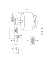
- FIG. 4 is a schematic view showing a configuration of a flywheel power generating facility of a third embodiment.
- the flywheel power generating facility in FIG. 4 includes a power detector 7.
- the power detector 7 monitors the electric power supplied from the power supply device 3 to the driving motor 2 via the controller 4.
- the controller 4 also includes an upper limit setting module 4b configured to set an upper limit of the electric power supplied to the driving motor 2.
- the controller 4 controls the operation of the driving motor 2 so that a power value detected by the power detector 7 does not exceed the upper limit set in the upper limit setting module 4b.
- the nuclear fusion test facility 6 needs large electric power during the plasma ignition period immediately after the start of operation, so that the rotational speed of the flywheel power generator 1 rapidly declines.
- the setting value of the rotational speed is set to the upper limit in the operational speed range as in the second embodiment, the difference between the electric power required for maintaining plasma and the output power of the driving motor 2 may rapidly increase, and the driving motor 2 may be operated with overpower.
- the electric power supplied from the controller 4 to the driving motor 2 is monitored by the power detector 7.
- the controller 4 limits the electric power supplied to the driving motor 2 to the upper limit set in the upper limit setting module 4b so that the electric power, which is supplied to the driving motor 2 while the electric power is supplied to the nuclear fusion test facility 6, does not exceed a rated value.
- duration of time taken for the operational speed to reach the upper limit "Vmax" in the operational speed range becomes longer than that of the second embodiment.
- the controller 4 of the present embodiment includes the upper limit setting module 4b configured to set the upper limit of the electric power supplied to the driving motor 2. Furthermore, the controller 4 controls the operation of the driving motor 2 so that the electric power supplied to the driving motor 2 does not exceed the upper limit.
- FIG. 5 is a graph showing operation of a flywheel power generating facility of a fourth embodiment.
- the setting value "V” in the speed setting module 4a of the first embodiment and the setting value "Vmax” in the speed setting module 4a of the second embodiment are fixed value.
- the controller 4 of the fourth embodiment includes the speed setting module 4a that can set a setting value that varies every moment during the electric power is supplied to the nuclear fusion test facility 6. More specifically, in the fourth embodiment, the setting value of the speed setting module 4a can be varied with time.
- the setting value (speed instruction value) of the speed setting module 4a that varies with time is referred to as a speed pattern.
- the controller 4 of the present embodiment calculates stored energy (rotational energy) required from the flywheel power generator 1 at each moment during the test operation of the nuclear fusion test facility 6, based on a required power pattern (output power pattern for the flywheel power generator 1) during the test operation.
- the controller 4 sets setting values (speed patterns) that vary every moment by using graphs, tables, functions or the like so that the minimum rotational speed required for attaining the stored energy is obtained. As a consequence, it becomes possible to operate the flywheel power generator 1 at the minimum rotational speed that can achieve the required power pattern of the nuclear fusion test facility 6.
- FIG. 5 An example of the rotational speed of the flywheel power generator 1 controlled with such setting values is shown as a curved line L 4 in FIG. 5 .
- the controller 4 of the present embodiment adjusts the rotational speed of the flywheel power generator 1 within a rotational speed variation width " ⁇ V" in order to provide a necessary amount of stored energy to the flywheel power generator 1 and to achieve the minimum rotational speed required for maintaining the stored energy.
- the rotational speed variation width " ⁇ V" is a speed width from "Vmax" to "Vmin”.
- the line L 4 is drawn as a straight line parallel to an axis "T" except immediately after T 2 and immediately before T 3 .
- the line L 4 is a curve line in actuality in many cases.
- the controller 4 of the present embodiment includes the speed setting module 4a that can set the setting value that varies with time.
- the minimum rotational speed required for attaining the test pattern can be traced by controlling the rotational speed of the flywheel power generator 1 during the test operation of the nuclear fusion test facility 6 in the way disclosed above in the present embodiment.
Landscapes
- Engineering & Computer Science (AREA)
- Power Engineering (AREA)
- Control Of Eletrric Generators (AREA)
- Supply And Distribution Of Alternating Current (AREA)
Abstract
Description
- This application is a continuation of International Application No.
PCT/JP2012/073631, filed on September 14, 2012 2011-224245, filed on October 11, 2011 - Embodiments described herein relate to a flywheel power generating facility and a method of operating the same.
-
FIG. 6 is a schematic view showing a configuration of a conventional flywheel power generating facility. - A
flywheel power generator 1 includes aflywheel 1 a for storing rotational energy (mechanical energy), and can convert the stored rotational energy into electric energy (electric power) to output the electric energy. For example, theflywheel power generator 1 is used to supply the electric power to a nuclearfusion test facility 6 which needs large current in a short period of time. InFIG. 6 , theflywheel power generator 1 is directly connected to adriving motor 2, and thedriving motor 2 is further connected to apower supply device 3. The drivingmotor 2 rotates theflywheel 1 a, and thepower supply device 3 supplies electric power to the drivingmotor 2. - When the
flywheel power generator 1 is used as a power source of the nuclearfusion test facility 6, the flywheel power generating facility accelerates theflywheel power generator 1 by the drivingmotor 2 to store the rotational energy in theflywheel 1 a before starting the operation of the nuclearfusion test facility 6. In this case, a detector 5 (e.g., a rotational speed detector) and a controller 4 (e.g., a rotational speed controller) are used in the flywheel power generating facility to realize stable acceleration control. For example, thedetector 5 detects a rotational speed of theflywheel 1a, and thecontroller 4 controls the operation of the drivingmotor 2 based on the detected rotational speed. - While the nuclear
fusion test facility 6 operates, theflywheel power generator 1 converts the stored rotational energy into the electric energy to supply the electric energy to the nuclearfusion test facility 6. As a consequence, the rotational speed of theflywheel 1 a declines with reduction in rotational energy. In the flywheel power generating facility, the operation of the nuclearfusion test facility 6 is stopped when the rotational speed declines to a preset speed, and then theflywheel power generator 1 is accelerated again by the drivingmotor 2. In the flywheel power generating facility, the acceleration of theflywheel power generator 1 and the supply of the electric power to the nuclearfusion test facility 6 are repeated so as to operation the nuclearfusion test facility 6 repeatedly. - When the flywheel power generating facility starts up or the rotational speed of the
flywheel 1 a is lowered, thecontroller 4 controls the operation of the drivingmotor 2 to increase the rotational speed of theflywheel 1 a up to a rated rotational speed. -
-
FIG. 1 is a schematic view showing a configuration of a flywheel power generating facility of a first embodiment; -
FIG. 2 is a graph showing operation of the flywheel power generating facility of the first embodiment; -
FIG. 3 is a graph showing operation of a flywheel power generating facility of a second embodiment; -
FIG. 4 is a schematic view showing a configuration of a flywheel power generating facility of a third embodiment; -
FIG. 5 is a graph showing operation of a flywheel power generating facility of a fourth embodiment; and -
FIG. 6 is a schematic view showing a configuration of a conventional flywheel power generating facility. - Embodiments will now be explained with reference to the accompanying drawings.
- In the conventional flywheel power generating facility, a wound rotor induction motor is employed as the driving
motor 2, and a speed controller using a liquid resistor provided to a secondary coil is employed as thecontroller 4. In the conventional flywheel power generating facility, while the electric power is supplied to the nuclearfusion test facility 6, a powersupply circuit breaker 3a in thepower supply device 3 is opened so as to stop the supply of the electric power from thepower supply device 3 to thedriving motor 2. - The first reason thereof is that the nuclear
fusion test facility 6 needs to be configured as a system completely independent of the power system of an electric power company since the nuclearfusion test facility 6 uses large electric power that changes abruptly. The second reason thereof is that the conventional flywheel power generating facility uses a water rheostat for acceleration control, so that it is not appropriate to use theflywheel power generator 1 during rapid change in rotational speed during the operation of the nuclearfusion test facility 6. - Therefore, the conventional
flywheel power generator 1 needed to have a power generation capacity and a flywheel size that enable the conventionalflywheel power generator 1 to store the maximum energy required from the nuclearfusion test facility 6. However, since operation time of the conventional nuclearfusion test facility 6 was as short as about 10 seconds at the maximum, it was possible to realize theflywheel power generator 1 capable of storing the maximum amount of energy required from the nuclearfusion test facility 6. - However, in recent nuclear fusion tests, long-time plasma operation as long as 5 minutes or more are being planned to be carried out. In the long-time operation of the nuclear
fusion test facility 6, the operating time during plasma ignition that needs large active power is short, whereas the operating time during a subsequent plasma maintenance period is long. Therefore, rotational energy loss (i.e., rotational speed decline) by loss of the flywheel power generating facility under operation is large. - Accordingly, if it is attempted to satisfy the operating time required from the nuclear
fusion test facility 6, the amount of necessary rotational energy is drastically increased. In order to fulfill this requirement with the conventional system configuration, it is necessary to make considerable increase in flywheel effect of theflywheel power generator 1. However, this necessitates theflywheel power generator 1 made far larger in size and weight than the conventional flywheel power generator, which may not only bring disadvantages to thegenerator 1 in terms of economical efficiency and delivery deadline but may also disable thegenerator 1 from being embodied. - In one embodiment, a flywheel power generating facility includes a flywheel power generator including a flywheel for storing rotational energy, and configured to convert the rotational energy into electric power to supply the electric power to a test facility. The generating facility further includes a driving motor configured to rotate the flywheel, and a power supply device configured to supply electric power to the driving motor. The generating facility further includes a detector configured to output a signal related to the rotation of the flywheel, and a controller configured to control operation of the driving motor, based on the outputted signal. The controller controls the operation of the driving motor so that the driving motor provides accelerating torque to the flywheel while the supply of the electric power to the test facility is stopped and while the electric power is supplied to the test facility.
-
FIG. 1 is a schematic view showing a configuration of a flywheel power generating facility of a first embodiment. The configuration ofFIG. 1 will be explained by highlighting the differences from the configuration ofFIG. 6 . - In
FIG. 1 , theflywheel power generator 1 is directly connected to thedriving motor 2, and thedriving motor 2 is a squirrel-cage induction motor. Thepower supply device 3 supplies AC power of a commercial frequency. The power delivery from thepower supply device 3 to the drivingmotor 2 is conducted via thecontroller 4 including a variable voltage variable frequency converter (VVVF). - The
detector 5 detects the rotational speed of theflywheel 1a, and thecontroller 4 controls the operation of the drivingmotor 2 based on the detected rotational speed. Thecontroller 4 includes aspeed setting module 4a configured to set a setting value of the rotational speed of theflywheel 1a. Thecontroller 4 controls the operation of the drivingmotor 2 by the VVVF so that the rotational speed of theflywheel 1a detected by thedetector 5 becomes equal to the above-stated setting value. In this way, the speed of theflywheel 1 a is controlled. - In the present embodiment, the power
supply circuit breaker 3a is closed not only before starting and while stopping a plasma test by the nuclearfusion test facility 6, but also while the plasma test is in operation. In other words, the power delivery from thepower supply device 3 in the present embodiment is performed not only while the supply of the electric power to the nuclearfusion test facility 6 is stopped but also while the electric power is supplied to the nuclearfusion test facility 6. - Furthermore, the
controller 4 continues operation not only while the supply of the electric power to the nuclearfusion test facility 6 is stopped, but also while the electric power is supplied to the nuclearfusion test facility 6 to continue the power delivery from thepower supply device 3 to the drivingmotor 2. Therefore, in the present embodiment, application of accelerating torque from the drivingmotor 2 to theflywheel 1 a is continued even while the electric power is supplied to the nuclearfusion test facility 6. - In this way, the
controller 4 of the present embodiment controls the operation of the drivingmotor 2 so that the drivingmotor 2 provides the accelerating torque to theflywheel 1 a while the supply of the electric power to the nuclearfusion test facility 6 is stopped and while the electric power is supplied to the nuclearfusion test facility 6. - Functions of the flywheel power generating facility of the first embodiment will be described with reference to
FIG. 1 continuously. - In
FIG. 1 , when the plasma test is started and the electric power is supplied from theflywheel power generator 1 to the nuclearfusion test facility 6, the rotational speed of theflywheel 1 a declines. Accordingly, thecontroller 4 supplies the electric power to the drivingmotor 2 during the plasma test so as to accelerate theflywheel 1 a. - Generally, output power of the
driving motor 2 is about several percents of the output power of theflywheel power generator 1. Therefore, in an initial several-second period during plasma ignition that requires large electric power (seeFIG. 2 ), power generation by theflywheel power generator 1 is generally performed by using the rotational energy stored in theflywheel 1a as an energy source. Therefore, during the plasma ignition, the rotational speed of theflywheel 1a rapidly declines. -
FIG. 2 is a graph showing operation of the flywheel power generating facility of the first embodiment.FIG. 2 shows that large electric power "P1" is supplied to the nuclearfusion test facility 6 during a plasma ignition period from "T1" to "T2". - In the present embodiment, the VVVF is therefore used in the
controller 4. Accordingly, even when the rotational speed of theflywheel 1 a rapidly changes in the present embodiment, electric power can stably be supplied to the drivingmotor 2 by controlling an effective voltage and a frequency of AC power supplied to the drivingmotor 2 at a high speed by the VVVF. - On the contrary, a plasma maintenance period from "T2" to "T3" (see
FIG. 2 ) is as long as several hundred seconds, and therefore the amount of energy required from the nuclearfusion test facility 6 is large. However, the necessary electric power "P2" is small as shown inFIG. 2 . - Therefore, even in consideration of the total loss including windage loss and bearing loss of the
flywheel power generator 1, it is still sufficiently possible to supply electric power of this level to the drivingmotor 2. Accordingly, it becomes possible in the present embodiment to maintain or increase the rotational speed of theflywheel 1a during the plasma maintenance period from "T2" to "T3". Therefore, thecontroller 4 of the present embodiment increases the rotational speed of theflywheel 1 a up to the setting value during the plasma maintenance period from "T2" to "T3", and once the rotational speed reaches the setting value, thecontroller 4 maintains this rotational speed of theflywheel 1 a. - In this way, the supply of the electric power from the driving
motor 2 to theflywheel power generator 1 is performed concurrently with the supply of the electric power from theflywheel power generator 1 to the nuclearfusion test facility 6 during the nuclear fusion test period from "T1" to "T4" in the present embodiment. In this case, if the former electric power is smaller than the latter electric power, energy storage into theflywheel power generator 1 is also executed at the same time. - Effects of the first embodiment will be described.
- As described above, the power delivery from the
power supply device 3 to the drivingmotor 2 is continued not only while the supply of the electric power to the nuclearfusion test facility 6 is stopped but also while the electric power is supplied to the nuclearfusion test facility 6 in the present embodiment. Therefore, the application of the accelerating torque from the drivingmotor 2 to theflywheel 1a is continued even while the electric power is supplied to the nuclearfusion test facility 6 in the present embodiment. As a consequence, the following effects can be obtained in the present embodiment. - In the present embodiment, it becomes possible to limit the energy amount stored in the
flywheel 1a to the level necessary for the plasma ignition by supplying the energy to be consumed during the plasma maintenance period from the drivingmotor 2. - Accordingly, when the nuclear
fusion test facility 6 is to be constructed, it becomes possible to construct the nuclearfusion test facility 6 that operates long time with a far smaller-sizeflywheel power generator 1, compared with the conventional case where the energy to be consumed during the plasma maintenance period is also stored in theflywheel 1a as the rotational energy. Employing the small-sizeflywheel power generator 1 makes it possible to achieve a shorter assembly period on site, reduced construction costs, and reduced building and facility costs. - In the present embodiment, the VVVF supporting the driving
motor 2 may additionally be provided while the existingflywheel power generator 1 is used. This makes it possible to realize operation tests for maintaining plasma for long time in the nuclearfusion test facility 6 such as JT60. This brings about large economic effects and contribution to the development of a fusion technology. - In this way, according to the present embodiment, it becomes possible to realize long-time operation of the nuclear
fusion test facility 6 while suppressing increase in the amount of rotational energy that can be stored in theflywheel power generator 1. - The flywheel power generating facility of the present embodiment may be applied to test facilities other than the nuclear
fusion test facility 6. Examples of such test facilities include particle accelerators. - The
detector 5 of the present embodiment may output a signal that holds information other than the rotational speed as the signal related to the rotation of theflywheel 1a, and thecontroller 4 of the present embodiment may control the operation of the drivingmotor 2 based on this outputted signal. For example, the signal may hold rotational acceleration of theflywheel 1 a. -
FIG. 3 is a graph showing operation of a flywheel power generating facility of a second embodiment. - In the present embodiment, the setting value of the
speed setting module 4a while the electric power is supplied to the nuclearfusion test facility 6 is set to an upper limit in an operating speed range of theflywheel power generator 1 inFIG. 1 . InFIG. 3 , a lower limit and the upper limit in the operating speed range of theflywheel power generator 1 are denoted by "Vmin" and "Vmax", respectively. - A curved line L1 in
FIG. 3 represents a change in the rotational speed of the flywheel power generator 1 (flywheel 1a) of the first embodiment. In the first embodiment, the setting value of thespeed setting module 4a while the electric power is supplied to the nuclearfusion test facility 6 is set to a speed "V" between "Vmin" and "Vmax". Consequently, the rotational speed of theflywheel power generator 1 is maintained at the speed "V" while the electric power is supplied to the nuclearfusion test facility 6. When the rotational speed is changed from the speed "V", thecontroller 4 controls the operation of the drivingmotor 2 to change back the rotational velocities to the speed "V". - A curved line L2 represents a change in the rotational speed of the
flywheel power generator 1 of the second embodiment. In the second embodiment, the setting value of thespeed setting module 4a while the electric power is supplied to the nuclearfusion test facility 6 is set to "Vmax". Consequently, while the electric power is supplied to the nuclearfusion test facility 6, thecontroller 6 controls the operation of the drivingmotor 2 to maintain the rotational speed of theflywheel power generator 1 at "Vmax". - A curved line L3 represents a change in the rotational speed of the
flywheel power generator 1 of a third embodiment. The curved line L3 will be described in the third embodiment. - Functions of the flywheel power generating facility of the second embodiment will be described with reference to
FIG. 3 continuously. - In the present embodiment, the setting value of the
speed setting module 4a is set to "Vmax", so that theflywheel power generator 1 is accelerated with the electric power equal to a difference between the electric power required for maintaining plasma and the maximum output electric power of the drivingmotor 2. As a result, the rotational speed of theflywheel power generator 1 which was slowed down during the plasma ignition is recovered up to "Vmax", and the maximum storable energy is stored in theflywheel power generator 1. - Immediately after the start of the plasma maintenance period, the
controller 4 controls the operation of the drivingmotor 2 so that the rotational speed of theflywheel power generator 1 returns to the upper limit "Vmax", thereby accelerating the rotational speed up to "Vmax". - The present embodiment is also effective in the case where, for example, the nuclear
fusion test facility 6 has a power consumption peak even during the plasma maintenance period. This is because a large volume of electric power is needed during such peak time, and the maximum storable energy is stored in theflywheel power generator 1 of the present embodiment prior to such peak time. - Effects of the second embodiment will be described.
- As described above, the setting value of the
speed setting module 4a while the electric power is supplied to the nuclearfusion test facility 6 is set to the upper limit "Vmax" in the operating speed range of theflywheel power generator 1 in the present embodiment. - Consequently, according to the present embodiment, the flywheel power generating facility can demonstrate maximum capacity while the electric power is supplied to the nuclear
fusion test facility 6. As a result, it becomes possible to enhance a degree of freedom in execution of the operation tests for maintaining plasma for long time in the nuclearfusion test facility 6 -
FIG. 4 is a schematic view showing a configuration of a flywheel power generating facility of a third embodiment. - In addition to the configuration of
FIG. 1 , the flywheel power generating facility inFIG. 4 includes a power detector 7. The power detector 7 monitors the electric power supplied from thepower supply device 3 to the drivingmotor 2 via thecontroller 4. - The
controller 4 also includes an upperlimit setting module 4b configured to set an upper limit of the electric power supplied to the drivingmotor 2. Thecontroller 4 controls the operation of the drivingmotor 2 so that a power value detected by the power detector 7 does not exceed the upper limit set in the upperlimit setting module 4b. - Functions of the flywheel power generating facility of the third embodiment will be described with reference to
FIG. 4 continuously. - As described in the first embodiment, the nuclear
fusion test facility 6 needs large electric power during the plasma ignition period immediately after the start of operation, so that the rotational speed of theflywheel power generator 1 rapidly declines. In this case, if the setting value of the rotational speed is set to the upper limit in the operational speed range as in the second embodiment, the difference between the electric power required for maintaining plasma and the output power of the drivingmotor 2 may rapidly increase, and the drivingmotor 2 may be operated with overpower. - Accordingly, in the present embodiment, the electric power supplied from the
controller 4 to the drivingmotor 2 is monitored by the power detector 7. Thecontroller 4 limits the electric power supplied to the drivingmotor 2 to the upper limit set in the upperlimit setting module 4b so that the electric power, which is supplied to the drivingmotor 2 while the electric power is supplied to the nuclearfusion test facility 6, does not exceed a rated value. - As a result, as shown with the curved line L3 in
FIG. 3 , duration of time taken for the operational speed to reach the upper limit "Vmax" in the operational speed range becomes longer than that of the second embodiment. However, according to the present embodiment, it becomes possible to prevent the overpower operation of the drivingmotor 2 and to realize stable operation of the drivingmotor 2 and thecontroller 4. - Effects of the third embodiment will be described.
- As described above, the
controller 4 of the present embodiment includes the upperlimit setting module 4b configured to set the upper limit of the electric power supplied to the drivingmotor 2. Furthermore, thecontroller 4 controls the operation of the drivingmotor 2 so that the electric power supplied to the drivingmotor 2 does not exceed the upper limit. - Consequently, according to the present embodiment, it becomes possible to realize stable operation within the capacity of the flywheel power generating facility and to achieve stable operation in the operation tests for maintaining plasma for long time in the nuclear
fusion test facility 6. -
FIG. 5 is a graph showing operation of a flywheel power generating facility of a fourth embodiment. - The setting value "V" in the
speed setting module 4a of the first embodiment and the setting value "Vmax" in thespeed setting module 4a of the second embodiment are fixed value. - On the contrary, the
controller 4 of the fourth embodiment includes thespeed setting module 4a that can set a setting value that varies every moment during the electric power is supplied to the nuclearfusion test facility 6. More specifically, in the fourth embodiment, the setting value of thespeed setting module 4a can be varied with time. Hereinafter, the setting value (speed instruction value) of thespeed setting module 4a that varies with time is referred to as a speed pattern. - Functions of the flywheel power generating facility of the fourth embodiment will be described with reference to
FIG. 5 continuously. - The
controller 4 of the present embodiment calculates stored energy (rotational energy) required from theflywheel power generator 1 at each moment during the test operation of the nuclearfusion test facility 6, based on a required power pattern (output power pattern for the flywheel power generator 1) during the test operation. - The
controller 4 sets setting values (speed patterns) that vary every moment by using graphs, tables, functions or the like so that the minimum rotational speed required for attaining the stored energy is obtained. As a consequence, it becomes possible to operate theflywheel power generator 1 at the minimum rotational speed that can achieve the required power pattern of the nuclearfusion test facility 6. - An example of the rotational speed of the
flywheel power generator 1 controlled with such setting values is shown as a curved line L4 inFIG. 5 . Thecontroller 4 of the present embodiment adjusts the rotational speed of theflywheel power generator 1 within a rotational speed variation width "ΔV" in order to provide a necessary amount of stored energy to theflywheel power generator 1 and to achieve the minimum rotational speed required for maintaining the stored energy. The rotational speed variation width "ΔV" is a speed width from "Vmax" to "Vmin". - In
FIG. 5 , the line L4 is drawn as a straight line parallel to an axis "T" except immediately after T2 and immediately before T3. However, the line L4 is a curve line in actuality in many cases. - Effects of the fourth embodiment will be described.
- As described above, the
controller 4 of the present embodiment includes thespeed setting module 4a that can set the setting value that varies with time. - Consequently, for example, the minimum rotational speed required for attaining the test pattern can be traced by controlling the rotational speed of the
flywheel power generator 1 during the test operation of the nuclearfusion test facility 6 in the way disclosed above in the present embodiment. - Mechanical loss such as windage loss and bearing loss during the operation of the
flywheel power generator 1 can be decreased with a lower rotational speed. Therefore, according to the present embodiment, it becomes possible to minimize the loss during operation and to minimize the electric energy required for the test operation of the nuclearfusion test facility 6. This brings about such advantages that electricity bills concerning the test operation of the nuclearfusion test facility 6 can be minimized, for example. - While certain embodiments have been described, these embodiments have been presented by way of example only, and are not intended to limit the scope of the inventions. Indeed, the novel facilities and methods described herein may be embodied in a variety of other forms; furthermore, various omissions, substitutions and changes in the form of the facilities and methods described herein may be made without departing from the spirit of the inventions. The accompanying claims and their equivalents are intended to cover such forms or modifications as would fall within the scope and spirit of the inventions.
Claims (8)
- A flywheel power generating facility comprising:a flywheel power generator including a flywheel for storing rotational energy, and configured to convert the rotational energy into electric power to supply the electric power to a test facility;a driving motor configured to rotate the flywheel;a power supply device configured to supply electric power to the driving motor;a detector configured to output a signal related to the rotation of the flywheel; anda controller configured to control operation of the driving motor, based on the outputted signal,wherein the controller controls the operation of the driving motor so that the driving motor provides accelerating torque to the flywheel while the supply of the electric power to the test facility is stopped and while the electric power is supplied to the test facility.
- The generating facility of Claim 1, wherein
the detector detects a rotational speed of the flywheel, and
the controller controls the operation of the driving motor, based on the rotational speed. - The generating facility of Claim 2, wherein
the controller comprises a speed setting module configured to set a setting value of the rotational speed, and
the controller controls the operation of the driving motor so that the rotational speed becomes the setting value. - The generating facility of Claim 3, wherein the setting value of the rotational speed is an upper limit of the rotational speed.
- The generating facility of Claim 3, wherein the speed setting module sets the setting value that varies with time.
- The generating facility of Claim 5, wherein the speed setting module sets the setting value to a minimum speed that enables the test facility to operate.
- The generating facility of Claim 1, wherein
the controller comprises an upper limit setting module configured to set an upper limit of the electric power supplied to the driving motor, and
the controller controls the operation of the driving motor so that the electric power supplied to the driving motor does not exceed the upper limit. - A method of operating a flywheel power generating facility, comprising controlling operation of a driving motor for rotating a flywheel of a flywheel power generator so that the driving motor provides accelerating torque to the flywheel while supply of electric power from the flywheel power generator to a test facility is stopped and while the electric power is supplied from the flywheel power generator to the test facility.
Applications Claiming Priority (2)
| Application Number | Priority Date | Filing Date | Title |
|---|---|---|---|
| JP2011224245A JP5740279B2 (en) | 2011-10-11 | 2011-10-11 | Flywheel power generation equipment and operation method thereof |
| PCT/JP2012/073631 WO2013054640A1 (en) | 2011-10-11 | 2012-09-14 | Flywheel power generating facility and operating method therefor |
Publications (3)
| Publication Number | Publication Date |
|---|---|
| EP2608358A1 true EP2608358A1 (en) | 2013-06-26 |
| EP2608358A4 EP2608358A4 (en) | 2015-04-22 |
| EP2608358B1 EP2608358B1 (en) | 2017-03-01 |
Family
ID=48081697
Family Applications (1)
| Application Number | Title | Priority Date | Filing Date |
|---|---|---|---|
| EP12830877.2A Not-in-force EP2608358B1 (en) | 2011-10-11 | 2012-09-14 | Flywheel power generating facility and operating method therefor |
Country Status (5)
| Country | Link |
|---|---|
| US (1) | US9300185B2 (en) |
| EP (1) | EP2608358B1 (en) |
| JP (1) | JP5740279B2 (en) |
| KR (1) | KR101516507B1 (en) |
| WO (1) | WO2013054640A1 (en) |
Families Citing this family (5)
| Publication number | Priority date | Publication date | Assignee | Title |
|---|---|---|---|---|
| US9578860B2 (en) | 2013-08-23 | 2017-02-28 | Allen Fly Fishing Llc | Fly reel with ratcheting drag system |
| JP6253394B2 (en) * | 2013-12-19 | 2017-12-27 | 株式会社ナップワン | Power device and power generator |
| JP7228126B2 (en) * | 2017-01-24 | 2023-02-24 | 住友電気工業株式会社 | Energy storage system and variable power stable utilization system |
| CN110488113A (en) * | 2019-07-10 | 2019-11-22 | 平高集团有限公司 | A test platform for flywheel energy storage system |
| KR102449428B1 (en) * | 2021-12-31 | 2022-09-30 | 조출규 | Flywheel power plant and power generation system including same |
Family Cites Families (9)
| Publication number | Priority date | Publication date | Assignee | Title |
|---|---|---|---|---|
| US5256907A (en) * | 1988-06-13 | 1993-10-26 | Mitsubishi Denki Kabushiki Kaisha | Electric power supply apparatus |
| CA2028866A1 (en) * | 1990-10-30 | 1992-05-01 | Miroslav Kopriva | Selfsustaining inertia generator |
| JPH08275444A (en) * | 1995-03-29 | 1996-10-18 | Tadashi Fukao | Flywheel drive system for energy storage |
| JPH09163639A (en) * | 1995-12-06 | 1997-06-20 | Toshiba Corp | Power supply and laser oscillator |
| JP2001197688A (en) * | 2000-01-14 | 2001-07-19 | Matsushita Electric Ind Co Ltd | Power storage device |
| JP2002345152A (en) * | 2001-05-15 | 2002-11-29 | Toshiba Corp | Control method and apparatus for variable speed flywheel generator |
| US20110049892A1 (en) * | 2009-08-06 | 2011-03-03 | Jonathan Ross | System For Efficient Energy Generation |
| JP5732723B2 (en) * | 2010-01-25 | 2015-06-10 | 株式会社Ihi | Flywheel power storage system |
| JP2011239553A (en) * | 2010-05-10 | 2011-11-24 | Hitachi Ltd | Power supply method for power supply system and power supply system |
-
2011
- 2011-10-11 JP JP2011224245A patent/JP5740279B2/en not_active Expired - Fee Related
-
2012
- 2012-09-14 KR KR1020137009310A patent/KR101516507B1/en not_active Expired - Fee Related
- 2012-09-14 EP EP12830877.2A patent/EP2608358B1/en not_active Not-in-force
- 2012-09-14 WO PCT/JP2012/073631 patent/WO2013054640A1/en not_active Ceased
-
2013
- 2013-03-13 US US13/798,565 patent/US9300185B2/en active Active
Also Published As
| Publication number | Publication date |
|---|---|
| KR101516507B1 (en) | 2015-05-04 |
| EP2608358B1 (en) | 2017-03-01 |
| EP2608358A4 (en) | 2015-04-22 |
| KR20130088154A (en) | 2013-08-07 |
| JP5740279B2 (en) | 2015-06-24 |
| US9300185B2 (en) | 2016-03-29 |
| JP2013085401A (en) | 2013-05-09 |
| US20130193788A1 (en) | 2013-08-01 |
| WO2013054640A1 (en) | 2013-04-18 |
Similar Documents
| Publication | Publication Date | Title |
|---|---|---|
| US9300185B2 (en) | Flywheel power generating facility and method of operating same | |
| US7394166B2 (en) | Method, apparatus and computer program product for wind turbine start-up and operation without grid power | |
| EP2302786A1 (en) | Excitation control system for marine diesel brushless doubly fed shaft generator and control method thereof | |
| US9444391B2 (en) | Protective module and method against torque peaks between a motor and an electric machine | |
| CN103546080B (en) | Control method for excitation type synchronous generator of wind power generation system | |
| JP2015056942A (en) | Hybrid power generation system | |
| CN113178897A (en) | Wind-storage combined system operation control method and control system | |
| JP2009254232A (en) | System and method related to operating variable speed generator | |
| CN112003332A (en) | Inertia-expandable phase modulator flywheel system and using method thereof | |
| AU2018206230B2 (en) | Power grid stabilising system | |
| JP2018061417A (en) | Electric motor driven generator and rotary system stabilizer | |
| JP2004260929A (en) | Wind power output stabilization device | |
| CN108777495B (en) | Coordination control method, frequency converter, excitation equipment and static frequency conversion starting system | |
| CN106803670B (en) | Low-cost wind-solar-diesel-storage DC microgrid battery charging control system and method | |
| CN119401516A (en) | Flywheel energy storage control method, system, device and storage medium | |
| WO2010003469A1 (en) | Power control module and method for controlling energy flow | |
| JP5098565B2 (en) | Induction motor excitation voltage control method for power regeneration device and power regeneration device | |
| JP2012100450A (en) | Power generation device with dc generator | |
| CN114640129A (en) | Alternating-current excitation variable-speed pumped storage system containing electrochemical energy storage and using method | |
| He et al. | Virtual Inertia Compensation Strategy for Variable Speed Pumped Storage Hydropower Unit | |
| Kimura et al. | Emergency power supply using flywheel and doubly fed induction generator | |
| KR102727049B1 (en) | Power generation system including ESS for power plant surplus energy recovery | |
| EP2912765B1 (en) | Dynamo-electric machine | |
| US12338741B2 (en) | Power capture during coast down of turbine generator | |
| JPS6359798A (en) | Water-wheel generator |
Legal Events
| Date | Code | Title | Description |
|---|---|---|---|
| PUAI | Public reference made under article 153(3) epc to a published international application that has entered the european phase |
Free format text: ORIGINAL CODE: 0009012 |
|
| 17P | Request for examination filed |
Effective date: 20130318 |
|
| AK | Designated contracting states |
Kind code of ref document: A1 Designated state(s): AL AT BE BG CH CY CZ DE DK EE ES FI FR GB GR HR HU IE IS IT LI LT LU LV MC MK MT NL NO PL PT RO RS SE SI SK SM TR |
|
| DAX | Request for extension of the european patent (deleted) | ||
| RA4 | Supplementary search report drawn up and despatched (corrected) |
Effective date: 20150323 |
|
| RIC1 | Information provided on ipc code assigned before grant |
Ipc: H02J 3/30 20060101ALI20150317BHEP Ipc: H02P 9/00 20060101ALI20150317BHEP Ipc: H02J 15/00 20060101AFI20150317BHEP |
|
| 17Q | First examination report despatched |
Effective date: 20151119 |
|
| GRAP | Despatch of communication of intention to grant a patent |
Free format text: ORIGINAL CODE: EPIDOSNIGR1 |
|
| INTG | Intention to grant announced |
Effective date: 20160822 |
|
| RIN1 | Information on inventor provided before grant (corrected) |
Inventor name: ARIHARA YOSHITAKA Inventor name: KAGEYAMA TAKAHISA Inventor name: ISHIZUKI, TERUYUKI |
|
| GRAS | Grant fee paid |
Free format text: ORIGINAL CODE: EPIDOSNIGR3 |
|
| GRAJ | Information related to disapproval of communication of intention to grant by the applicant or resumption of examination proceedings by the epo deleted |
Free format text: ORIGINAL CODE: EPIDOSDIGR1 |
|
| GRAL | Information related to payment of fee for publishing/printing deleted |
Free format text: ORIGINAL CODE: EPIDOSDIGR3 |
|
| GRAR | Information related to intention to grant a patent recorded |
Free format text: ORIGINAL CODE: EPIDOSNIGR71 |
|
| INTC | Intention to grant announced (deleted) | ||
| RIN1 | Information on inventor provided before grant (corrected) |
Inventor name: ISHIZUKI, TERUYUKI Inventor name: ARIHARA YOSHITAKA Inventor name: KAGEYAMA TAKAHISA |
|
| GRAA | (expected) grant |
Free format text: ORIGINAL CODE: 0009210 |
|
| RIC1 | Information provided on ipc code assigned before grant |
Ipc: H02K 7/02 20060101ALI20170110BHEP Ipc: H02P 9/00 20060101ALI20170110BHEP Ipc: H02K 7/18 20060101ALI20170110BHEP Ipc: H02J 15/00 20060101AFI20170110BHEP Ipc: H02J 3/30 20060101ALI20170110BHEP Ipc: H02P 3/00 20060101ALI20170110BHEP |
|
| INTG | Intention to grant announced |
Effective date: 20170118 |
|
| AK | Designated contracting states |
Kind code of ref document: B1 Designated state(s): AL AT BE BG CH CY CZ DE DK EE ES FI FR GB GR HR HU IE IS IT LI LT LU LV MC MK MT NL NO PL PT RO RS SE SI SK SM TR |
|
| REG | Reference to a national code |
Ref country code: GB Ref legal event code: FG4D |
|
| REG | Reference to a national code |
Ref country code: CH Ref legal event code: EP Ref country code: AT Ref legal event code: REF Ref document number: 872378 Country of ref document: AT Kind code of ref document: T Effective date: 20170315 |
|
| REG | Reference to a national code |
Ref country code: IE Ref legal event code: FG4D |
|
| REG | Reference to a national code |
Ref country code: DE Ref legal event code: R096 Ref document number: 602012029369 Country of ref document: DE |
|
| REG | Reference to a national code |
Ref country code: NL Ref legal event code: MP Effective date: 20170301 |
|
| REG | Reference to a national code |
Ref country code: LT Ref legal event code: MG4D |
|
| REG | Reference to a national code |
Ref country code: AT Ref legal event code: MK05 Ref document number: 872378 Country of ref document: AT Kind code of ref document: T Effective date: 20170301 |
|
| PG25 | Lapsed in a contracting state [announced via postgrant information from national office to epo] |
Ref country code: FI Free format text: LAPSE BECAUSE OF FAILURE TO SUBMIT A TRANSLATION OF THE DESCRIPTION OR TO PAY THE FEE WITHIN THE PRESCRIBED TIME-LIMIT Effective date: 20170301 Ref country code: LT Free format text: LAPSE BECAUSE OF FAILURE TO SUBMIT A TRANSLATION OF THE DESCRIPTION OR TO PAY THE FEE WITHIN THE PRESCRIBED TIME-LIMIT Effective date: 20170301 Ref country code: NO Free format text: LAPSE BECAUSE OF FAILURE TO SUBMIT A TRANSLATION OF THE DESCRIPTION OR TO PAY THE FEE WITHIN THE PRESCRIBED TIME-LIMIT Effective date: 20170601 Ref country code: GR Free format text: LAPSE BECAUSE OF FAILURE TO SUBMIT A TRANSLATION OF THE DESCRIPTION OR TO PAY THE FEE WITHIN THE PRESCRIBED TIME-LIMIT Effective date: 20170602 Ref country code: HR Free format text: LAPSE BECAUSE OF FAILURE TO SUBMIT A TRANSLATION OF THE DESCRIPTION OR TO PAY THE FEE WITHIN THE PRESCRIBED TIME-LIMIT Effective date: 20170301 |
|
| REG | Reference to a national code |
Ref country code: FR Ref legal event code: PLFP Year of fee payment: 6 |
|
| PG25 | Lapsed in a contracting state [announced via postgrant information from national office to epo] |
Ref country code: ES Free format text: LAPSE BECAUSE OF FAILURE TO SUBMIT A TRANSLATION OF THE DESCRIPTION OR TO PAY THE FEE WITHIN THE PRESCRIBED TIME-LIMIT Effective date: 20170301 Ref country code: LV Free format text: LAPSE BECAUSE OF FAILURE TO SUBMIT A TRANSLATION OF THE DESCRIPTION OR TO PAY THE FEE WITHIN THE PRESCRIBED TIME-LIMIT Effective date: 20170301 Ref country code: RS Free format text: LAPSE BECAUSE OF FAILURE TO SUBMIT A TRANSLATION OF THE DESCRIPTION OR TO PAY THE FEE WITHIN THE PRESCRIBED TIME-LIMIT Effective date: 20170301 Ref country code: SE Free format text: LAPSE BECAUSE OF FAILURE TO SUBMIT A TRANSLATION OF THE DESCRIPTION OR TO PAY THE FEE WITHIN THE PRESCRIBED TIME-LIMIT Effective date: 20170301 Ref country code: AT Free format text: LAPSE BECAUSE OF FAILURE TO SUBMIT A TRANSLATION OF THE DESCRIPTION OR TO PAY THE FEE WITHIN THE PRESCRIBED TIME-LIMIT Effective date: 20170301 Ref country code: BG Free format text: LAPSE BECAUSE OF FAILURE TO SUBMIT A TRANSLATION OF THE DESCRIPTION OR TO PAY THE FEE WITHIN THE PRESCRIBED TIME-LIMIT Effective date: 20170601 |
|
| PG25 | Lapsed in a contracting state [announced via postgrant information from national office to epo] |
Ref country code: NL Free format text: LAPSE BECAUSE OF FAILURE TO SUBMIT A TRANSLATION OF THE DESCRIPTION OR TO PAY THE FEE WITHIN THE PRESCRIBED TIME-LIMIT Effective date: 20170301 |
|
| PG25 | Lapsed in a contracting state [announced via postgrant information from national office to epo] |
Ref country code: EE Free format text: LAPSE BECAUSE OF FAILURE TO SUBMIT A TRANSLATION OF THE DESCRIPTION OR TO PAY THE FEE WITHIN THE PRESCRIBED TIME-LIMIT Effective date: 20170301 Ref country code: IT Free format text: LAPSE BECAUSE OF FAILURE TO SUBMIT A TRANSLATION OF THE DESCRIPTION OR TO PAY THE FEE WITHIN THE PRESCRIBED TIME-LIMIT Effective date: 20170301 Ref country code: RO Free format text: LAPSE BECAUSE OF FAILURE TO SUBMIT A TRANSLATION OF THE DESCRIPTION OR TO PAY THE FEE WITHIN THE PRESCRIBED TIME-LIMIT Effective date: 20170301 Ref country code: SK Free format text: LAPSE BECAUSE OF FAILURE TO SUBMIT A TRANSLATION OF THE DESCRIPTION OR TO PAY THE FEE WITHIN THE PRESCRIBED TIME-LIMIT Effective date: 20170301 Ref country code: CZ Free format text: LAPSE BECAUSE OF FAILURE TO SUBMIT A TRANSLATION OF THE DESCRIPTION OR TO PAY THE FEE WITHIN THE PRESCRIBED TIME-LIMIT Effective date: 20170301 |
|
| PG25 | Lapsed in a contracting state [announced via postgrant information from national office to epo] |
Ref country code: SM Free format text: LAPSE BECAUSE OF FAILURE TO SUBMIT A TRANSLATION OF THE DESCRIPTION OR TO PAY THE FEE WITHIN THE PRESCRIBED TIME-LIMIT Effective date: 20170301 Ref country code: PT Free format text: LAPSE BECAUSE OF FAILURE TO SUBMIT A TRANSLATION OF THE DESCRIPTION OR TO PAY THE FEE WITHIN THE PRESCRIBED TIME-LIMIT Effective date: 20170703 Ref country code: PL Free format text: LAPSE BECAUSE OF FAILURE TO SUBMIT A TRANSLATION OF THE DESCRIPTION OR TO PAY THE FEE WITHIN THE PRESCRIBED TIME-LIMIT Effective date: 20170301 Ref country code: IS Free format text: LAPSE BECAUSE OF FAILURE TO SUBMIT A TRANSLATION OF THE DESCRIPTION OR TO PAY THE FEE WITHIN THE PRESCRIBED TIME-LIMIT Effective date: 20170701 |
|
| REG | Reference to a national code |
Ref country code: DE Ref legal event code: R097 Ref document number: 602012029369 Country of ref document: DE |
|
| PLBE | No opposition filed within time limit |
Free format text: ORIGINAL CODE: 0009261 |
|
| STAA | Information on the status of an ep patent application or granted ep patent |
Free format text: STATUS: NO OPPOSITION FILED WITHIN TIME LIMIT |
|
| PG25 | Lapsed in a contracting state [announced via postgrant information from national office to epo] |
Ref country code: DK Free format text: LAPSE BECAUSE OF FAILURE TO SUBMIT A TRANSLATION OF THE DESCRIPTION OR TO PAY THE FEE WITHIN THE PRESCRIBED TIME-LIMIT Effective date: 20170301 |
|
| 26N | No opposition filed |
Effective date: 20171204 |
|
| PG25 | Lapsed in a contracting state [announced via postgrant information from national office to epo] |
Ref country code: SI Free format text: LAPSE BECAUSE OF FAILURE TO SUBMIT A TRANSLATION OF THE DESCRIPTION OR TO PAY THE FEE WITHIN THE PRESCRIBED TIME-LIMIT Effective date: 20170301 |
|
| REG | Reference to a national code |
Ref country code: DE Ref legal event code: R119 Ref document number: 602012029369 Country of ref document: DE |
|
| REG | Reference to a national code |
Ref country code: CH Ref legal event code: PL |
|
| GBPC | Gb: european patent ceased through non-payment of renewal fee |
Effective date: 20170914 |
|
| PG25 | Lapsed in a contracting state [announced via postgrant information from national office to epo] |
Ref country code: MC Free format text: LAPSE BECAUSE OF FAILURE TO SUBMIT A TRANSLATION OF THE DESCRIPTION OR TO PAY THE FEE WITHIN THE PRESCRIBED TIME-LIMIT Effective date: 20170301 |
|
| REG | Reference to a national code |
Ref country code: IE Ref legal event code: MM4A |
|
| REG | Reference to a national code |
Ref country code: BE Ref legal event code: MM Effective date: 20170930 |
|
| PG25 | Lapsed in a contracting state [announced via postgrant information from national office to epo] |
Ref country code: LU Free format text: LAPSE BECAUSE OF NON-PAYMENT OF DUE FEES Effective date: 20170914 |
|
| PG25 | Lapsed in a contracting state [announced via postgrant information from national office to epo] |
Ref country code: DE Free format text: LAPSE BECAUSE OF NON-PAYMENT OF DUE FEES Effective date: 20180404 Ref country code: CH Free format text: LAPSE BECAUSE OF NON-PAYMENT OF DUE FEES Effective date: 20170930 Ref country code: IE Free format text: LAPSE BECAUSE OF NON-PAYMENT OF DUE FEES Effective date: 20170914 Ref country code: LI Free format text: LAPSE BECAUSE OF NON-PAYMENT OF DUE FEES Effective date: 20170930 Ref country code: GB Free format text: LAPSE BECAUSE OF NON-PAYMENT OF DUE FEES Effective date: 20170914 |
|
| REG | Reference to a national code |
Ref country code: FR Ref legal event code: PLFP Year of fee payment: 7 |
|
| PG25 | Lapsed in a contracting state [announced via postgrant information from national office to epo] |
Ref country code: BE Free format text: LAPSE BECAUSE OF NON-PAYMENT OF DUE FEES Effective date: 20170930 |
|
| PG25 | Lapsed in a contracting state [announced via postgrant information from national office to epo] |
Ref country code: MT Free format text: LAPSE BECAUSE OF NON-PAYMENT OF DUE FEES Effective date: 20170914 |
|
| PG25 | Lapsed in a contracting state [announced via postgrant information from national office to epo] |
Ref country code: HU Free format text: LAPSE BECAUSE OF FAILURE TO SUBMIT A TRANSLATION OF THE DESCRIPTION OR TO PAY THE FEE WITHIN THE PRESCRIBED TIME-LIMIT; INVALID AB INITIO Effective date: 20120914 |
|
| PG25 | Lapsed in a contracting state [announced via postgrant information from national office to epo] |
Ref country code: CY Free format text: LAPSE BECAUSE OF NON-PAYMENT OF DUE FEES Effective date: 20170301 |
|
| PG25 | Lapsed in a contracting state [announced via postgrant information from national office to epo] |
Ref country code: MK Free format text: LAPSE BECAUSE OF FAILURE TO SUBMIT A TRANSLATION OF THE DESCRIPTION OR TO PAY THE FEE WITHIN THE PRESCRIBED TIME-LIMIT Effective date: 20170301 |
|
| PG25 | Lapsed in a contracting state [announced via postgrant information from national office to epo] |
Ref country code: TR Free format text: LAPSE BECAUSE OF FAILURE TO SUBMIT A TRANSLATION OF THE DESCRIPTION OR TO PAY THE FEE WITHIN THE PRESCRIBED TIME-LIMIT Effective date: 20170301 |
|
| PG25 | Lapsed in a contracting state [announced via postgrant information from national office to epo] |
Ref country code: AL Free format text: LAPSE BECAUSE OF FAILURE TO SUBMIT A TRANSLATION OF THE DESCRIPTION OR TO PAY THE FEE WITHIN THE PRESCRIBED TIME-LIMIT Effective date: 20170301 |
|
| PGFP | Annual fee paid to national office [announced via postgrant information from national office to epo] |
Ref country code: FR Payment date: 20230710 Year of fee payment: 12 |
|
| PG25 | Lapsed in a contracting state [announced via postgrant information from national office to epo] |
Ref country code: FR Free format text: LAPSE BECAUSE OF NON-PAYMENT OF DUE FEES Effective date: 20240930 |