EP2608221A2 - Induction loop cable - Google Patents
Induction loop cable Download PDFInfo
- Publication number
- EP2608221A2 EP2608221A2 EP20120008537 EP12008537A EP2608221A2 EP 2608221 A2 EP2608221 A2 EP 2608221A2 EP 20120008537 EP20120008537 EP 20120008537 EP 12008537 A EP12008537 A EP 12008537A EP 2608221 A2 EP2608221 A2 EP 2608221A2
- Authority
- EP
- European Patent Office
- Prior art keywords
- line
- induction loop
- loop line
- conductor
- stretchable
- Prior art date
- Legal status (The legal status is an assumption and is not a legal conclusion. Google has not performed a legal analysis and makes no representation as to the accuracy of the status listed.)
- Withdrawn
Links
Images

Classifications
-
- H—ELECTRICITY
- H01—ELECTRIC ELEMENTS
- H01B—CABLES; CONDUCTORS; INSULATORS; SELECTION OF MATERIALS FOR THEIR CONDUCTIVE, INSULATING OR DIELECTRIC PROPERTIES
- H01B7/00—Insulated conductors or cables characterised by their form
- H01B7/17—Protection against damage caused by external factors, e.g. sheaths or armouring
- H01B7/18—Protection against damage caused by wear, mechanical force or pressure; Sheaths; Armouring
- H01B7/182—Protection against damage caused by wear, mechanical force or pressure; Sheaths; Armouring comprising synthetic filaments
- H01B7/1825—Protection against damage caused by wear, mechanical force or pressure; Sheaths; Armouring comprising synthetic filaments forming part of a high tensile strength core
-
- H—ELECTRICITY
- H01—ELECTRIC ELEMENTS
- H01B—CABLES; CONDUCTORS; INSULATORS; SELECTION OF MATERIALS FOR THEIR CONDUCTIVE, INSULATING OR DIELECTRIC PROPERTIES
- H01B7/00—Insulated conductors or cables characterised by their form
- H01B7/06—Extensible conductors or cables, e.g. self-coiling cords
-
- H—ELECTRICITY
- H01—ELECTRIC ELEMENTS
- H01B—CABLES; CONDUCTORS; INSULATORS; SELECTION OF MATERIALS FOR THEIR CONDUCTIVE, INSULATING OR DIELECTRIC PROPERTIES
- H01B7/00—Insulated conductors or cables characterised by their form
- H01B7/32—Insulated conductors or cables characterised by their form with arrangements for indicating defects, e.g. breaks or leaks
- H01B7/328—Insulated conductors or cables characterised by their form with arrangements for indicating defects, e.g. breaks or leaks comprising violation sensing means
Definitions
- the EP 0 425 977 A2 deals with the problem of possible damage to induction loop cables due to changing weather conditions and vehicle load.
- this publication of the prior art finds the solution to insert the winding of the induction loop in a hollow profile open on one side and to shed with a curable plastic in the hollow profile.
- the hollow profile is made of PVC.
- This insulation which may consist of one or more insulation layers, serves to insulate and also protect the outer conductor.
- This insulation which may consist of one or more insulation layers, serves to insulate and also protect the outer conductor.
- For outside mechanical and thermal protection of Ladder and to increase the stability of the line may be at least partially surrounded by at least one device for outside mechanical and thermal protection and to increase the stability of the line, in particular from an externally arranged braid, in particular a braid of impregnated glass fibers.
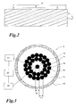
- FIG. 1 1 shows a cross-sectional view of an induction loop line 1.
- This comprises a stretchable core element 10 arranged centrally in the line 1, two layers of electrical conductors 12 on the core element 10 and an insulation layer 13 surrounding the conductors 12.
- the line 1 is surrounded or encased by a mesh layer 14. This can for example have impregnated glass fibers.
- the electrical conductors 12 are made of copper, for example. In the in FIG. 1 In the embodiment shown, 30 such copper conductors or wires are arranged in a strand around the core element 10 in two layers.
- the layer arranged on the kernel element 10 comprises 12 conductors 12, the second layer 18 conductors 12. Basically, it is also possible here to arrange more or fewer conductors 12 around the centrally arranged core element 10 or to provide an arrangement in more than two layers.
- a tensile stress of the core member 10 in the longitudinal direction leads to a reduction of the diameter d 10 of the core element 10.
- the resistance and the other electrical properties of the induction loop line 1 thus remain the same over a wide range of traction. Only with excessive tensile stress can it also come here to change the electrical properties of the line 1.
- the change in the diameter of the central core element 10 under tensile stress can also be used for line failure monitoring or for monitoring the change in the road surface / road surface into which the induction loop line 1 is inserted.
- the core element 10 is modified. This comprises a blind conductor 11 approximately in the center of the line 1, which is surrounded by an insulating layer 15.
- a core wire is provided instead of the core element 10 provided without a conductor.
- the blind conductor 11 may for example consist of copper.
- the conductors 12 are arranged in a stranded. The arrangement can be as in FIG. 2 indicated.
- the resistance of the dummy conductor 11 increases under tensile stress with a corresponding reduction in its diameter, so that a query of the resistance by the in FIG. 3 indicated measuring device 20 of the centrally arranged blind conductor 11 can be determined whether it is stretched due to excessive tensile stress, so elongated.
- the thickness or layer thickness s 15 of the insulation layer 15 can be monitored by a measuring device 21.
- the layer thickness s 15 of the insulating layer 15 is also reduced. From a certain minimum layer thickness, there is an electrical breakdown, indicating the exceeding of the yield strength of the line.
- By monitoring the resistance of the dummy conductor 11 and the layer thickness s 15 of the insulating layer 15 can early a significant tensile stress of the induction loop line due to changes in the road surface / the Road surface in which it is arranged by an in FIG. 3 only indicated evaluation unit 22 are detected as possible before an electrical breakdown through the insulation layer and thus an early required replacement of the induction loop line done.
- each line to avoid failures under tensile stress has at least one tensile force-absorbing stretchable part or at least partially stretchable is formed, in particular has a stretchable in the longitudinal direction of the conduit centrally arranged in the line region which does not serve the electrical line and the electrical conductors are arranged around it.
Abstract
Description
Die Erfindung betrifft eine Induktionsschleifen-Leitung mit zumindest einem elektrischen Leiter und zumindest einer Isolierung.The invention relates to an induction loop line with at least one electrical conductor and at least one insulation.
Induktionsschleifen werden üblicherweise in Fahrbahnen angeordnet, wobei sie beispielsweise zur Erfassung der Anwesenheit von Fahrzeugen vor einer Ampel, zur Geschwindigkeitserfassung oder für andere Verkehrsüberwachungen dienen. Eine Induktionsschleife wird üblicherweise von Wechselstrom durchflossen, den ein Oszillator erzeugt. Frequenzbestimmend ist dabei die Schleifeninduktivität in Verbindung mit der Zuleitung. Der Schleifenstrom führt zu einem magnetischen Wechselfeld, das in den Metallteilen eines sich über der Induktionsschleife aufhaltenden Fahrzeugs Wirbelströme erzeugt, die ihrerseits das Wechselfeld beeinflussen, so dass die Schleifeninduktivität sinkt. Dies führt zu einem Anstieg der Schleifenfrequenz. Die Änderung der Schleifeninduktivität dient somit der Fahrzeugerkennung und wird von einem Detektor erfasst.Induction loops are usually arranged in lanes, for example, they serve to detect the presence of vehicles in front of a traffic light, for speed detection or other traffic monitoring. An induction loop is usually traversed by alternating current, which generates an oscillator. Frequency determining is the loop inductance in connection with the supply line. The loop current leads to an alternating magnetic field, which generates eddy currents in the metal parts of a vehicle located above the induction loop, which in turn influence the alternating field, so that the loop inductance decreases. This leads to an increase in the loop frequency. The change in the loop inductance thus serves to detect the vehicle and is detected by a detector.
Als problematisch hat sich herausgestellt, dass Fahrbahnen bzw. der Straßenbelag im Laufe der Zeit partiell absacken können, so dass es zu Höhenunterschieden im Bereich der Verlegung der Induktionsschleifen-Leitung kommt. Hierdurch wird die Induktionsschleifen-Leitung einer Zugbeanspruchung ausgesetzt, die zu einer Verringerung des Leiterquerschnitts bis hin zu einem Riss der Leitung, somit zu deren Unbrauchbarkeit und Ausfall führen kann.As problematic it has been found that roads or the road surface can partially sag over time, so that there is a difference in height in the field of laying the induction loop line. As a result, the induction loop line is subjected to a tensile stress, which can lead to a reduction of the conductor cross-section up to a crack of the line, thus to their uselessness and failure.
Die
Der vorliegenden Erfindung liegt nun die Aufgabe zugrunde, eine Induktionsschleifen-Leitung vorzusehen, bei der der negative Effekt einer Leiterquerschnittsverringerung, also ein Ausfall einer solchen Leitung möglichst vermieden werden kann. Ferner liegt der vorliegenden Erfindung auch die Aufgabe zugrunde, eine Veränderung des Straßenbelags bzw. einer Fahrbahndecke möglichst frühzeitig zu erkennen, um einen Leitungsausfall zu vermeiden.The present invention is now based on the object to provide an induction loop line, wherein the negative effect of a Conductor cross-section reduction, so a failure of such a line can be avoided as possible. Furthermore, the present invention is also the object of detecting a change in the road surface or a road surface as early as possible in order to avoid a line failure.
Die Aufgabe wird für eine Induktionsschleifen-Leitung nach dem Oberbegriff des Anspruchs 1 dadurch gelöst, dass die Leitung zum Vermeiden von Ausfällen bei Zugbeanspruchung zumindest einen Zugkraft aufnehmenden, in Längsrichtung der Leitung dehnfähigen Teil aufweist. Für eine Einrichtung zur Leitungsausfallüberwachung unter Verwendung einer Induktionsschleifen-Leitung wird die Aufgabe dadurch gelöst, dass die Einrichtung Mittel zum Überwachen des Widerstandes des Zugkraft aufnehmenden, in Längsrichtung der Leitung dehnfähigen Teils der Induktionsschleifen-Leitung sowie Mittel zum Ermitteln eines elektrischen Durchschlags durch eine Isolierung des dehnfähigen Teils der Induktionsschleifen-Leitung oder Mittel zum Ermitteln der Isolationsdicke der einen Blindleiter des Kernelements des dehnfähigen Teils umgebenden Isolierung umfasst. Weiterbildungen der Erfindung sind in den abhängigen Ansprüchen definiert.The object is achieved for an induction loop line according to the preamble of
Dadurch wird eine Induktionsschleifen-Leitung geschaffen, die aufgrund ihrer zumindest teilweisen Dehnfähigkeit oder Dehnbarkeit in Längsrichtung der Leitung eine Zugbeanspruchung kompensieren kann, da der zumindest eine Zugkraft aufnehmende dehnfähige Teil diese aufnimmt und dadurch der zumindest eine Leiter nicht oder zumindest über eine weite Strecke hinweg nicht mehr der Gefahr eines Reißens unterliegt und somit Leitungsausfälle vermieden werden können. Eine Zugbeanspruchung wird durch das Vorsehen der Dehnfähigkeit bzw. hohen Bruchdehnung des zumindest einen Teils der Induktionsschleifen-Leitung abgefangen und somit die Funktionsfähigkeit der Leiter und der Leitung aufrecht erhalten.As a result, an induction loop line is provided, which can compensate for a tensile stress due to their at least partial extensibility or extensibility in the longitudinal direction of the line, since the at least one tensile absorbing elastic part absorbs them and thus the at least one conductor not or at least not over a long distance More subject to the risk of tearing and thus line failures can be avoided. Tensile stress is absorbed by the provision of the high elongation at break of the at least one part of the induction loop line, thus maintaining the operability of the conductors and the line.
Vorteilhaft ist der zumindest eine Leiter an den dehnfähigen Teil so angekoppelt, dass eine Zugbeanspruchung durch die Schlaglänge des Leiters abgefangen wird. Bei Aufbringen einer Zugkraft auf die Leitung dehnt sich der dehnfähige Teil in Längsrichtung der Leitung aus und die Schlaglänge des Leiters vergrößert sich.Advantageously, the at least one conductor is coupled to the expansible part in such a way that a tensile stress is absorbed by the lay length of the conductor becomes. Upon application of a tensile force on the line, the stretchable part expands in the longitudinal direction of the line and the lay length of the conductor increases.
Weiter vorteilhaft umfasst der dehnfähige Teil ein dehnfähiges bezüglich der Leitung mittig angeordnetes Kernelement. Besonders vorteilhaft ist das dehnfähige mittig angeordnete Kernelement ein Kunststoffelement. Insbesondere besteht dieses aus PTFE, also Polytetrafluorethylen, somit einem Material mit einem niedrigen E-Modul von unter 1.000 N/mm2 und einer hohen Bruchdehnung von z.B. 250 bis 500 %. Es kann z.B. in Form einer Kunststoffschnur ausgebildet sein. Dieses dehnfähige mittig bzw. zentral in der Leitung angeordnete Kernelement kann sich bei Zugbeanspruchung dehnen, wodurch sich sein Durchmesser verringert bzw. es sich verjüngt und seine Länge zunimmt.Further advantageously, the stretchable part comprises a stretchable with respect to the line centrally arranged core element. Particularly advantageous is the stretchable centrally arranged core element is a plastic element. In particular, this consists of PTFE, ie polytetrafluoroethylene, thus a material with a low modulus of less than 1000 N / mm 2 and a high elongation at break of eg 250 to 500%. It may be formed, for example in the form of a plastic cord. This stretchable central element arranged centrally in the conduit can stretch under tensile stress, thereby reducing or tapering its diameter and increasing its length.
Der dehnfähige Teil, insbesondere das dehnfähige mittig angeordnete Kernelement, kann auf seiner Außenseite von einer Anzahl von Leitern umgeben sein. Diese sind vorteilhaft um den dehnfähigen Teil, insbesondere das dehnfähige mittig angeordnete Kernelement, herum verseilt. Hierdurch kann eine Zerstörung der Leiter, die insbesondere aus Kupfer bestehen, vermieden werden, da sich bei einem Einwirken einer Zugkraft auf die Induktionsschleifen-Leitung der Durchmesser des dehnfähigen Teils bzw. des dehnfähigen mittig in der Leitung angeordneten Kernelements verringert, sich hierbei die Schlaglänge der diesen bzw. diese umgebenden Leiter vergrößert, ohne dass die Leiter selbst auf Zug belastet werden, wodurch sich ihr Durchmesser verringern bzw. sie sich verjüngen würden. Somit kann ein Leiterbruch aufgrund Zugbelastung der Induktionsschleifen-Leitung wirksam vermieden werden. Ferner ändern sich die elektrischen Eigenschaften der Induktionsschleifen-Leitung über einen weiten Bereich hinweg nicht, da lediglich der dehnfähige Teil bzw. das dehnfähige mittig in der Leitung angeordnete Kernelement belastet wird, nicht jedoch die diese umgebenden Leiter der Induktionsschleifen-Leitung.The stretchable part, in particular the stretchable centrally arranged core element, may be surrounded on its outside by a number of conductors. These are advantageously around the stretchable part, in particular the stretchable centrally arranged core element, stranded around. In this way, a destruction of the conductors, which consist in particular of copper, can be avoided, since the diameter of the expansible part or of the stretchable centrally arranged in the line core element is reduced in an action of a tensile force on the induction loop line, this is the lay length of this or this surrounding conductor increases, without the conductors themselves being loaded on train, which would reduce their diameter or they would be rejuvenated. Thus, a wire break due to tensile load of the induction loop line can be effectively avoided. Furthermore, the electrical properties of the induction loop line do not change over a wide range, since only the stretchable part or core element which is arranged centrally in the line is loaded, but not the surrounding conductors of the induction loop line.
Als weiter vorteilhaft erweist es sich, den zumindest einen Leiter umgebend eine Isolierung vorzusehen. Diese Isolierung, die aus einer oder mehreren Isolationsschichten bestehen kann, dient der Isolierung und auch dem äußeren Schutz der Leiter. Zum außenseitigen mechanischen und thermischen Schutz der Leiter und zur Erhöhung der Stabilität der Leitung kann diese von zumindest einer Einrichtung zum außenseitigen mechanischen und thermischen Schutz und zur Erhöhung der Stabilität der Leitung zumindest teilweise umgeben sein, insbesondere von einem außenseitig angeordneten Geflecht, insbesondere einem Geflecht aus imprägnierten Glasfasern. Durch das Vorsehen einer solchen Einrichtung bzw. insbesondere des Geflechtes ist einerseits ein äußerer Schutz gegen Beschädigung gegeben, vor allem auch, während als äußere Schicht einer Fahrbahn eine Teerdecke auf die Induktionsschleifen-Leitung aufgebracht wird. Andererseits ist eine Biegsamkeit der Leitung gegeben, wobei durch das Vorsehen imprägnierter Glasfasern neben dem mechanischen und thermischen Schutz eine besondere Stabilität der äußeren Ummantelung der Leitung vorgesehen werden kann. Dies erweist sich aufgrund der Anordnung in einer Fahrbahndecke nicht nur bei dem Fertigen derselben, sondern auch im Betrieb als sehr vorteilhaft, da die mechanischen Beanspruchungen einer solchen Induktionsschleifen-Leitung durch darüber fahrende Fahrzeuge und Umwelteinflüsse hoch sein können.As further advantageous, it proves to provide the at least one conductor surrounding an insulation. This insulation, which may consist of one or more insulation layers, serves to insulate and also protect the outer conductor. For outside mechanical and thermal protection of Ladder and to increase the stability of the line may be at least partially surrounded by at least one device for outside mechanical and thermal protection and to increase the stability of the line, in particular from an externally arranged braid, in particular a braid of impregnated glass fibers. By providing such a device or in particular the braiding on the one hand, an external protection against damage is given, above all, while a tar cover is applied to the induction loop line as the outer layer of a roadway. On the other hand, a flexibility of the line is given, which can be provided by the provision of impregnated glass fibers in addition to the mechanical and thermal protection, a special stability of the outer sheath of the line. This proves to be very advantageous because of the arrangement in a road surface not only in the manufacture of the same, but also in operation, since the mechanical stresses of such an induction loop line can be high by driving overhead vehicles and environmental influences.
Beispielsweise kann der Nennquerschnitt der das dehnfähige mittig in der Leitung angeordnete Kernelement umgebenden Leiter 1 bis 2 mm2, insbesondere 1,5 mm2, betragen. Der Widerstand der Leiter kann beispielsweise maximal 13 Ω/km betragen.By way of example, the nominal cross section of the conductor which surrounds the expansible core element arranged centrally in the line can be 1 to 2 mm 2 , in particular 1.5 mm 2 . The resistance of the conductors can be, for example, a maximum of 13 Ω / km.
Der dehnfähige Teil der Induktionsschleifen-Leitung kann weiter vorteilhaft zu Überwachungszwecken im Hinblick auf die Veränderung des Straßenbelags bzw. der Fahrbahn im Bereich der Induktionsschleifen-Leitung verwendet werden. Das Kernelement kann dabei einen innenliegenden Blindleiter zum Überwachen eines Leitungsausfalls umfassen. Als Blindleiter eignet sich beispielsweise ein Kupferleiter. Dieser ist vorteilhaft in das Kernelement eingebettet, so dass das Material des Kernelements als Isolierung des Blindleiters dient, so dass dieser als Kernader ausgebildet ist. Wird die Induktionsschleifen-Leitung auf Zug beansprucht, dehnt sich der dehnfähige Teil, insbesondere die mittig in der Leitung angeordnete dehnfähige Kernader, aus, verjüngt sich dabei, während sie sich längt und ihr Widerstand sich hierdurch erhöht. In Abhängigkeit von dem Widerstand des dehnfähigen Teils bzw. der mittig in der Leitung angeordneten dehnfähigen Kernader kann das Ausmaß der Dehnung ermittelt werden. Dies ist über eine Auswerteeinrichtung möglich, die das Mittel zum Überwachen des Widerstandes des dehnfähigen Teils bzw. der dehnfähigen mittig in der Leitung angeordneten Kernader der Induktionsschleifen-Leitung abfragt und basierend auf den ermittelten Widerstandswerten die Dehnung errechnet. Zusätzlich kann über das Mittel zum Ermitteln eines elektrischen Durchschlags durch die Isolierung des dehnfähigen Teils der Induktionsschleifen-Leitung die Funktionsfähigkeit der Induktionsschleifen-Leitung überwacht werden. Anstelle des Vorsehens der Mittel zum Überwachen eines elektrischen Durchschlags durch die Isolierung des Blindleiters können auch Mittel zum Ermitteln der Isolationsdicke der den Blindleiter umgebenden Isolierung vorgesehen werden. Basierend auf der Information betreffend die Dicke der den Blindleiter der Leitung umgebenden Isolierung kann auf die Gefahr eines elektrischen Durchschlags geschlossen werden. Eine dementsprechende Auswertung kann in einer Auswerteeinheit erfolgen. Diese kann bei drohendem elektrischen Durchschlag frühzeitig eine Warnmeldung abgeben bzw. an eine entsprechende Signaleinrichtung weiterleiten, die die Warnmeldung ausgibt. Die Auswerteeinheit kann somit basierend auf der Information, betreffend den elektrischen Widerstand des dehnfähigen Teils, bzw. auf der Information, betreffend die Dicke der Isolierung des Blindleiters, die Auswertung im Hinblick auf einen drohenden Ausfall der Induktionsschleifen-Leitung vornehmen. Sofern eine Auswerteeinheit feststellt, dass der Widerstand des dehnfähigen Teils ansteigt und/oder die Dicke der Isolierung des Blindleiters einen zu geringen Wert annimmt, also aufgrund der Zugbeanspruchung es zu einer Verringerung der Isolationsschichtdicke kommt, steht ein elektrischer Durchschlag zu befürchten und sie gibt eine entsprechende Warnmeldung aus bzw. an die Signaleinrichtung ab. Somit kann frühzeitig die Gefahr eines Leitungsausfalls der Induktionsschleifen-Leitung erkannt werden, da frühzeitig Veränderungen des Straßenbelages bzw. der Fahrbahndecke, in der die Induktionsschleifen-Leitung angeordnet ist, festgestellt und ggf. ein Austausch der Induktionsschleifen-Leitung frühzeitig vorgenommen werden kann.The stretchable part of the induction loop line can be further advantageously used for monitoring purposes with regard to the change of the road surface or in the area of the induction loop line. The core element may include an inner blind conductor for monitoring a line failure. As a blind conductor, for example, a copper conductor is suitable. This is advantageously embedded in the core element, so that the material of the core element serves as insulation of the blind conductor, so that it is designed as a core wire. If the induction loop line is subjected to tensile stress, the stretchable part, in particular the elastic core core arranged centrally in the line, expands, thereby tapering as it lengthens and its resistance thereby increases. Depending on the resistance of the expansible part or arranged centrally in the conduit stretchable core vein, the extent of elongation can be determined. This is possible via an evaluation device which interrogates the means for monitoring the resistance of the expansible part or the stretchable core wire of the induction loop line arranged centrally in the line and calculates the expansion on the basis of the resistance values determined. In addition, through the means for detecting an electrical breakdown by isolating the expansible portion of the induction loop line, the operability of the induction loop line can be monitored. Instead of providing the means for monitoring an electrical breakdown by the insulation of the blind conductor and means for determining the insulation thickness of the blind conductor surrounding insulation can be provided. Based on the information concerning the thickness of the insulation surrounding the stub conductor of the line, the risk of electrical breakdown can be deduced. A corresponding evaluation can be carried out in an evaluation unit. This can give early warning of a threat of electrical breakdown or forward to a corresponding signaling device that outputs the warning message. The evaluation unit can thus carry out the evaluation with regard to an imminent failure of the induction loop line based on the information relating to the electrical resistance of the expansible part, or on the information relating to the thickness of the insulation of the blind conductor. If an evaluation determines that the resistance of the stretchable part increases and / or the thickness of the insulation of the dummy conductor assumes too low value, so due to the tensile stress it comes to a reduction of the insulation layer thickness, an electric breakdown is to be feared and it gives a corresponding Warning message from or to the signaling device from. Thus, early the risk of line failure of the induction loop line can be detected because early changes in the road surface or the road surface, in which the induction loop line is arranged, determined and possibly an exchange of the induction loop line can be made early.
Zur näheren Erläuterung der Erfindung werden im Folgenden Ausführungsbeispiele von dieser näher anhand der Zeichnungen beschrieben. Diese zeigen in:
-
Figur 1 -
Figur 2 eine skizzenhafte Seitenansicht der Induktionsschleifen-Leitung gemäßFigur 1 -
Figur 3 eine Querschnittsansicht einer zweiten Ausführungsform einer erfindungsgemäßen Induktionsschleifen-Leitung.
-
FIG. 1 a cross-sectional view of a first embodiment of an inventive induction loop line, -
FIG. 2 a sketchy side view of the induction loop line according toFIG. 1 and -
FIG. 3 a cross-sectional view of a second embodiment of an induction loop line according to the invention.
Das mittig in der Leitung 1 angeordnete, dehnfähige Kernelement 10 besteht beispielsweise aus PTFE (Polytetrafluorethylen) oder einem anderen Polymermaterial. Es weist z.B. einen maximalen Durchmesser von 0,8 mm auf. Auch die Isolationsschicht 13 kann aus PTFE bestehen. Beispielsweise weist sie eine Schichtdicke von 0,45 mm auf. Der Nennquerschnitt der Leiter 12, die das dehnfähige mittig in der Leitung 1 angeordnete Kernelement 10 umgeben, beträgt beispielsweise 1 bis 2 mm2, insbesondere 1,5 mm2.The
Die elektrischen Leiter 12 bestehen beispielsweise aus Kupfer. In dem in
Wie aus
Die Veränderung des Durchmessers des zentralen Kernelements 10 bei Zugbeanspruchung kann auch zur Leitungsausfallüberwachung bzw. zur Überwachung der Veränderung des Straßenbelags/der Fahrbahndecke, in den/die die Induktionsschleifen-Leitung 1 eingefügt ist, verwendet werden. Hierzu wird, wie in
Ferner kann die Stärke bzw. Schichtdicke s15 der Isolationsschicht 15 durch eine Messeinrichtung 21 überwacht werden. Bei Aufbringen einer Zugkraft auf diese verringert sich die Schichtdicke s15 der Isolationsschicht 15 ebenfalls. Ab einer bestimmten minimalen Schichtdicke kommt es zu einem elektrischen Durchschlag, der das Überschreiten der Dehngrenze der Leitung anzeigt. Durch die Überwachung des Widerstandes des Blindleiters 11 sowie der Schichtdicke s15 der Isolationsschicht 15 kann frühzeitig eine deutliche Zugbeanspruchung der Induktionsschleifen-Leitung aufgrund Veränderungen des Straßenbelages/der Fahrbahndecke, in dem oder der sie angeordnet ist, durch eine in
Neben den im Vorstehenden genannten und in den Zeichnungen gezeigten Ausführungsvarianten einer Induktionsschleifen-Leitung sowie einer Einrichtung zur Leitungsausfallüberwachung können noch zahlreiche weitere gebildet werden, bei denen jeweils die Leitung zum Vermeiden von Ausfällen bei Zugbeanspruchung zumindest einen Zugkraft aufnehmenden dehnfähigen Teil aufweist bzw. zumindest teilweise dehnfähig ausgebildet ist, insbesondere einen in Längsrichtung der Leitung dehnfähigen mittig in der Leitung angeordneten Bereich aufweist, der nicht der elektrischen Leitung dient und die elektrischen Leiter um diesen herum angeordnet sind.In addition to the above-mentioned and shown in the drawings embodiments of an induction loop line and a device for line failure monitoring many more can be formed in which each line to avoid failures under tensile stress has at least one tensile force-absorbing stretchable part or at least partially stretchable is formed, in particular has a stretchable in the longitudinal direction of the conduit centrally arranged in the line region which does not serve the electrical line and the electrical conductors are arranged around it.
- 11
- Induktionsschleifen-LeitungInductive loop line
- 1010
- dehnfähiges mittig in der Leitung angeordnetes Kernelementstretchable centrally located in the line core element
- 1111
- elektrischer Blindleiterelectrical blind conductor
- 1212
- elektrischer Leiterelectrical conductor
- 1313
- Isolationsschichtinsulation layer
- 1414
- Geflechtschichtbraided layer
- 1515
- Isolierschichtinsulating
- 2020
- Messeinrichtung zur Ermittlung des Widerstands des BlindleitersMeasuring device for determining the resistance of the blind conductor
- 2121
-
Messeinrichtung zur Ermittlung der Stärke der Isolationsschicht 15Measuring device for determining the thickness of the insulating
layer 15 - 2222
- Auswerteeinheitevaluation
- d10 d 10
- Durchmesser des KernelementsDiameter of the core element
- d11 11
- Durchmesser des BlindleitersDiameter of the dummy conductor
- s15 s 15
-
Schichtdicke der Isolationsschicht 15Layer thickness of the insulating
layer 15 - SS
- Schlaglänge der LeiterLay length of the ladder
- S'S '
- vergrößerte Schlaglänge der Leiter bei Zugbeanspruchungincreased lay length of the ladder under tensile stress
Claims (11)
dadurch gekennzeichnet, dass
die Leitung (1) zum Vermeiden von Ausfällen bei Zugbeanspruchung zumindest einen Zugkraft aufnehmenden, in Längsrichtung der Leitung (1) dehnfähigen Teil (10,11,15) aufweist.Induction loop line (1) with at least one electrical conductor (12) and at least one insulation (13),
characterized in that
the line (1) to avoid failures under tensile stress at least one tensile force receiving, in the longitudinal direction of the line (1) stretchable part (10,11,15).
dadurch gekennzeichnet, dass
der zumindest eine Leiter (12) an den dehnfähigen Teil (10,11) so angekoppelt ist, dass eine Zugbeanspruchung durch die Schlaglänge (S) des Leiters (12) abgefangen wird.Induction loop line (1) according to claim 1,
characterized in that
the at least one conductor (12) is coupled to the expansible part (10, 11) in such a way that a tensile stress is absorbed by the lay length (S) of the conductor (12).
dadurch gekennzeichnet, dass
der dehnfähige Teil (10,11) ein dehnfähiges bezüglich der Leitung (1) mittig angeordnetes Kernelement (10) umfasst.Induction loop line (1) according to claim 1 or 2,
characterized in that
the expansible part (10, 11) comprises a stretchable core element (10) arranged centrally with respect to the conduit (1).
dadurch gekennzeichnet, dass
das dehnfähige mittig angeordnete Kernelement (10) ein Kunststoffelement ist, insbesondere aus PTFE besteht.Induction loop line (1) according to claim 3,
characterized in that
the extensible centrally arranged core element (10) is a plastic element, in particular consists of PTFE.
dadurch gekennzeichnet, dass
der dehnfähige Teil, insbesondere das dehnfähige mittig angeordnete Kernelement (10), auf seiner Außenseite von einer Anzahl von Leitern (12) umgeben ist.Induction loop line (1) according to claim 3 or 4,
characterized in that
the stretchable part, in particular the stretchable centrally arranged core element (10) is surrounded on its outside by a number of conductors (12).
dadurch gekennzeichnet, dass
die Leiter (12) um den dehnfähigen Teil, insbesondere das dehnfähige mittig angeordnete Kernelement (10), herum verseilt sind.Induction loop line (1) according to claim 5,
characterized in that
the conductors (12) are stranded around the stretchable part, in particular the stretchable centered core element (10).
dadurch gekennzeichnet, dass
den zumindest einen Leiter (12) umgebend eine Isolierung (13) vorgesehen ist.Induction loop line (1) according to one of the preceding claims,
characterized in that
the at least one conductor (12) surrounding an insulation (13) is provided.
dadurch gekennzeichnet, dass
die Leitung (1) außenseitig von einem Geflecht (14) umgeben ist, insbesondere einem Geflecht aus imprägnierten Glasfasern.Induction loop line (1) according to one of the preceding claims,
characterized in that
the line (1) is surrounded on the outside by a braid (14), in particular a braid of impregnated glass fibers.
dadurch gekennzeichnet, dass
der Nennquerschnitt der das dehnfähige mittig in der Leitung (1) angeordnete Kernelement (10) umgebenden Leiter (12) 1 bis 2 mm2, insbesondere 1,5 mm2, beträgt.Induction loop line (1) according to one of claims 3 to 8,
characterized in that
the nominal cross-section of the conductor (12) surrounding the stretchable central element (10) arranged centrally in the line (1) is 1 to 2 mm 2 , in particular 1.5 mm 2 .
dadurch gekennzeichnet dass,
das Kernelement (10) einen innenliegenden Blindleiter (11) zum Überwachen eines Leitungsausfalls umfasst.Induction line (1) according to one of the preceding claims,
characterized in that
the core element (10) comprises an inner stub (11) for monitoring a line failure.
dadurch gekennzeichnet, dass
die Einrichtung Mittel (20) zum Überwachen des Widerstandes des Zugkraft aufnehmenden dehnfähigen Teils (10) der Induktionsschleifen-Leitung (1) sowie Mittel zum Ermitteln eines elektrischen Durchschlags durch eine Isolierung (15) des dehnfähigen Teils (10) der Induktionsschleifen-Leitung (1) oder Mittel (21) zum Ermitteln der Isolationsdicke (s15) der einen Blindleiter (11) des Kernelements (10) des dehnfähigen Teils (10) umgebenden Isolierung (15) umfasst.Device for line failure monitoring using an induction loop line (1) according to one of the preceding claims, in particular according to claim 10,
characterized in that
the means (20) for monitoring the resistance of the tensile force-receiving expansible part (10) of the induction loop line (1) and means for determining an electrical breakdown by an insulation (15) of the expansible portion (10) of the induction loop line (1 ) or means (21) for determining the Insulation thickness (s 15 ) of a blind conductor (11) of the core element (10) of the stretchable part (10) surrounding insulation (15).
Applications Claiming Priority (1)
| Application Number | Priority Date | Filing Date | Title |
|---|---|---|---|
| DE201110122132 DE102011122132A1 (en) | 2011-12-22 | 2011-12-22 | Inductive loop line |
Publications (1)
| Publication Number | Publication Date |
|---|---|
| EP2608221A2 true EP2608221A2 (en) | 2013-06-26 |
Family
ID=47713753
Family Applications (1)
| Application Number | Title | Priority Date | Filing Date |
|---|---|---|---|
| EP20120008537 Withdrawn EP2608221A2 (en) | 2011-12-22 | 2012-12-21 | Induction loop cable |
Country Status (2)
| Country | Link |
|---|---|
| EP (1) | EP2608221A2 (en) |
| DE (1) | DE102011122132A1 (en) |
Citations (1)
| Publication number | Priority date | Publication date | Assignee | Title |
|---|---|---|---|---|
| EP0425977A2 (en) | 1989-11-02 | 1991-05-08 | Werner Beck | Induction loop |
Family Cites Families (3)
| Publication number | Priority date | Publication date | Assignee | Title |
|---|---|---|---|---|
| US2953760A (en) * | 1958-09-29 | 1960-09-20 | Gadget Of The Month Club Inc | Traffic counting cable |
| GB2063503B (en) * | 1979-11-15 | 1983-05-11 | Standard Telephones Cables Ltd | Monitoring strain inoptic fibre cable |
| DE102007041981A1 (en) * | 2007-09-05 | 2009-03-12 | Hew-Kabel/Cdt Gmbh & Co. Kg | Highly flexible shielded electrical data cable |
-
2011
- 2011-12-22 DE DE201110122132 patent/DE102011122132A1/en not_active Withdrawn
-
2012
- 2012-12-21 EP EP20120008537 patent/EP2608221A2/en not_active Withdrawn
Patent Citations (1)
| Publication number | Priority date | Publication date | Assignee | Title |
|---|---|---|---|---|
| EP0425977A2 (en) | 1989-11-02 | 1991-05-08 | Werner Beck | Induction loop |
Also Published As
| Publication number | Publication date |
|---|---|
| DE102011122132A1 (en) | 2013-06-27 |
Similar Documents
| Publication | Publication Date | Title |
|---|---|---|
| EP3520122B1 (en) | Electric cable having a coolant line | |
| DE2934684C2 (en) | Live or earth rope | |
| DE102013005901A1 (en) | Grounding cable i.e. rail grounding cable, for grounding e.g. handrails in station areas, has monitoring line surrounded by sleeve-like, pressure-resistant supporting element, which includes supporting wires that are coiled around line | |
| EP1490881B1 (en) | Three-conductor cable | |
| DE2021172B2 (en) | Electric cable for high and very high voltage loads, especially with polyethylene insulation | |
| EP1225598B1 (en) | Flexible electrical line | |
| EP2495733B1 (en) | Flexible electric cable | |
| DE102014111734A1 (en) | Monitoring system for a power cable, power cable for such a monitoring system and method for monitoring a power cable using such a monitoring system | |
| EP3433198B1 (en) | Lift system with load-bearing means partially surrounded by an electrically conductive housing, in particular at a deflection roller assembly | |
| DE102006015878B4 (en) | Flexible electrical control line | |
| CH709972A2 (en) | Electrical cable. | |
| EP1617544B1 (en) | Linear motor with a winding | |
| DE102009043164A1 (en) | Stranded electrical cable for control signal or power transmission in e.g. automobile wiring, includes up to seven twisted copper- and copper-zinc alloy cores | |
| WO2017076984A1 (en) | Data cable and use of the data cable in a motor vehicle | |
| DE102008031337B3 (en) | Electric sector conductor label of the Millikentyp | |
| EP0311751B1 (en) | Flexible power line, particularly heavy-duty cable with integrated lightwave conductors. | |
| EP2608221A2 (en) | Induction loop cable | |
| DE102018103909A1 (en) | Arrangement comprising a pipeline and a device for monitoring thereof | |
| DE3810714C2 (en) | ||
| DE102011016966A1 (en) | Cooling duct for high power cable used for induction furnace, has line sensor for detecting temperature of cooling portion, which is provided with distributed measurement points over the length of cooling portion | |
| DE102015211763A1 (en) | Electrical conduit and method of making such | |
| EP1378778B1 (en) | Protection hose of an optical fiber cable for laser applications | |
| DE2942925A1 (en) | HUMIDITY PROTECTED ELECTRIC CABLE | |
| WO2019174675A1 (en) | Sensor line and measuring assembly | |
| DE102013208250A1 (en) | Protective tube with electromagnetic shielding |
Legal Events
| Date | Code | Title | Description |
|---|---|---|---|
| AK | Designated contracting states |
Kind code of ref document: A2 Designated state(s): AL AT BE BG CH CY CZ DE DK EE ES FI FR GB GR HR HU IE IS IT LI LT LU LV MC MK MT NL NO PL PT RO RS SE SI SK SM TR |
|
| AX | Request for extension of the european patent |
Extension state: BA ME |
|
| PUAI | Public reference made under article 153(3) epc to a published international application that has entered the european phase |
Free format text: ORIGINAL CODE: 0009012 |
|
| STAA | Information on the status of an ep patent application or granted ep patent |
Free format text: STATUS: THE APPLICATION IS DEEMED TO BE WITHDRAWN |
|
| 18D | Application deemed to be withdrawn |
Effective date: 20150701 |