EP2608209A1 - Resistive memory array - Google Patents
Resistive memory array Download PDFInfo
- Publication number
- EP2608209A1 EP2608209A1 EP11194761.0A EP11194761A EP2608209A1 EP 2608209 A1 EP2608209 A1 EP 2608209A1 EP 11194761 A EP11194761 A EP 11194761A EP 2608209 A1 EP2608209 A1 EP 2608209A1
- Authority
- EP
- European Patent Office
- Prior art keywords
- lines
- resistive memory
- wordlines
- memory array
- bitlines
- Prior art date
- Legal status (The legal status is an assumption and is not a legal conclusion. Google has not performed a legal analysis and makes no representation as to the accuracy of the status listed.)
- Withdrawn
Links
- 238000004519 manufacturing process Methods 0.000 claims abstract description 15
- 239000000758 substrate Substances 0.000 claims description 56
- 238000000034 method Methods 0.000 claims description 25
- 229910052751 metal Inorganic materials 0.000 claims description 14
- 239000002184 metal Substances 0.000 claims description 14
- 239000000463 material Substances 0.000 description 80
- 239000011149 active material Substances 0.000 description 18
- 239000004020 conductor Substances 0.000 description 15
- 239000004065 semiconductor Substances 0.000 description 13
- 230000008901 benefit Effects 0.000 description 12
- VYPSYNLAJGMNEJ-UHFFFAOYSA-N Silicium dioxide Chemical compound O=[Si]=O VYPSYNLAJGMNEJ-UHFFFAOYSA-N 0.000 description 11
- 239000003989 dielectric material Substances 0.000 description 11
- 239000011810 insulating material Substances 0.000 description 11
- 239000007772 electrode material Substances 0.000 description 10
- 238000005530 etching Methods 0.000 description 10
- 230000008569 process Effects 0.000 description 10
- 238000000151 deposition Methods 0.000 description 9
- 229910021420 polycrystalline silicon Inorganic materials 0.000 description 9
- 238000003491 array Methods 0.000 description 8
- ATJFFYVFTNAWJD-UHFFFAOYSA-N Tin Chemical compound [Sn] ATJFFYVFTNAWJD-UHFFFAOYSA-N 0.000 description 7
- 230000004044 response Effects 0.000 description 7
- 229910052718 tin Inorganic materials 0.000 description 7
- 229910052782 aluminium Inorganic materials 0.000 description 6
- 229910052681 coesite Inorganic materials 0.000 description 6
- 229910052906 cristobalite Inorganic materials 0.000 description 6
- 238000005498 polishing Methods 0.000 description 6
- -1 poly-silicon Chemical class 0.000 description 6
- 229920005591 polysilicon Polymers 0.000 description 6
- 229910052682 stishovite Inorganic materials 0.000 description 6
- 229910052905 tridymite Inorganic materials 0.000 description 6
- 239000000377 silicon dioxide Substances 0.000 description 5
- 229910052802 copper Inorganic materials 0.000 description 4
- 230000006870 function Effects 0.000 description 4
- WOCIAKWEIIZHES-UHFFFAOYSA-N ruthenium(iv) oxide Chemical compound O=[Ru]=O WOCIAKWEIIZHES-UHFFFAOYSA-N 0.000 description 4
- 229910052719 titanium Inorganic materials 0.000 description 4
- 229910052726 zirconium Inorganic materials 0.000 description 4
- 229910052581 Si3N4 Inorganic materials 0.000 description 3
- 230000015572 biosynthetic process Effects 0.000 description 3
- 230000001419 dependent effect Effects 0.000 description 3
- 229910044991 metal oxide Inorganic materials 0.000 description 3
- 150000004706 metal oxides Chemical class 0.000 description 3
- 239000012782 phase change material Substances 0.000 description 3
- 229910052697 platinum Inorganic materials 0.000 description 3
- 229910052710 silicon Inorganic materials 0.000 description 3
- 239000010703 silicon Substances 0.000 description 3
- HQVNEWCFYHHQES-UHFFFAOYSA-N silicon nitride Chemical compound N12[Si]34N5[Si]62N3[Si]51N64 HQVNEWCFYHHQES-UHFFFAOYSA-N 0.000 description 3
- 239000007784 solid electrolyte Substances 0.000 description 3
- 239000000126 substance Substances 0.000 description 3
- 229910052721 tungsten Inorganic materials 0.000 description 3
- JBRZTFJDHDCESZ-UHFFFAOYSA-N AsGa Chemical compound [As]#[Ga] JBRZTFJDHDCESZ-UHFFFAOYSA-N 0.000 description 2
- 229910019044 CoSix Inorganic materials 0.000 description 2
- 229910000618 GeSbTe Inorganic materials 0.000 description 2
- 229910003327 LiNbO3 Inorganic materials 0.000 description 2
- 229910005889 NiSix Inorganic materials 0.000 description 2
- 229910018321 SbTe Inorganic materials 0.000 description 2
- 229910000577 Silicon-germanium Inorganic materials 0.000 description 2
- 229910004166 TaN Inorganic materials 0.000 description 2
- 229910004200 TaSiN Inorganic materials 0.000 description 2
- 229910008482 TiSiN Inorganic materials 0.000 description 2
- 229910008486 TiSix Inorganic materials 0.000 description 2
- 229910008599 TiW Inorganic materials 0.000 description 2
- 229910045601 alloy Inorganic materials 0.000 description 2
- 239000000956 alloy Substances 0.000 description 2
- 238000000231 atomic layer deposition Methods 0.000 description 2
- 238000005229 chemical vapour deposition Methods 0.000 description 2
- 229910052804 chromium Inorganic materials 0.000 description 2
- 150000001875 compounds Chemical class 0.000 description 2
- 238000005520 cutting process Methods 0.000 description 2
- 230000008021 deposition Effects 0.000 description 2
- 239000002019 doping agent Substances 0.000 description 2
- 230000008020 evaporation Effects 0.000 description 2
- 238000001704 evaporation Methods 0.000 description 2
- 239000011521 glass Substances 0.000 description 2
- 229910052735 hafnium Inorganic materials 0.000 description 2
- HTXDPTMKBJXEOW-UHFFFAOYSA-N iridium(IV) oxide Inorganic materials O=[Ir]=O HTXDPTMKBJXEOW-UHFFFAOYSA-N 0.000 description 2
- 229910052742 iron Inorganic materials 0.000 description 2
- QRXWMOHMRWLFEY-UHFFFAOYSA-N isoniazide Chemical compound NNC(=O)C1=CC=NC=C1 QRXWMOHMRWLFEY-UHFFFAOYSA-N 0.000 description 2
- PWPJGUXAGUPAHP-UHFFFAOYSA-N lufenuron Chemical compound C1=C(Cl)C(OC(F)(F)C(C(F)(F)F)F)=CC(Cl)=C1NC(=O)NC(=O)C1=C(F)C=CC=C1F PWPJGUXAGUPAHP-UHFFFAOYSA-N 0.000 description 2
- 150000002739 metals Chemical class 0.000 description 2
- 229910003465 moissanite Inorganic materials 0.000 description 2
- 229910052750 molybdenum Inorganic materials 0.000 description 2
- 229910052759 nickel Inorganic materials 0.000 description 2
- 229910052758 niobium Inorganic materials 0.000 description 2
- 150000004767 nitrides Chemical class 0.000 description 2
- 229910052763 palladium Inorganic materials 0.000 description 2
- 230000003071 parasitic effect Effects 0.000 description 2
- 238000000059 patterning Methods 0.000 description 2
- 229920002120 photoresistant polymer Polymers 0.000 description 2
- 238000004549 pulsed laser deposition Methods 0.000 description 2
- 238000001552 radio frequency sputter deposition Methods 0.000 description 2
- 150000003346 selenoethers Chemical class 0.000 description 2
- 229910021332 silicide Inorganic materials 0.000 description 2
- 229910010271 silicon carbide Inorganic materials 0.000 description 2
- 229910052709 silver Inorganic materials 0.000 description 2
- 238000002207 thermal evaporation Methods 0.000 description 2
- 229910052723 transition metal Inorganic materials 0.000 description 2
- 150000003624 transition metals Chemical class 0.000 description 2
- 229910052720 vanadium Inorganic materials 0.000 description 2
- 229910021521 yttrium barium copper oxide Inorganic materials 0.000 description 2
- 229910001218 Gallium arsenide Inorganic materials 0.000 description 1
- GPXJNWSHGFTCBW-UHFFFAOYSA-N Indium phosphide Chemical compound [In]#P GPXJNWSHGFTCBW-UHFFFAOYSA-N 0.000 description 1
- 229910002244 LaAlO3 Inorganic materials 0.000 description 1
- 241001082241 Lythrum hyssopifolia Species 0.000 description 1
- 229910015345 MOn Inorganic materials 0.000 description 1
- 229910004491 TaAlN Inorganic materials 0.000 description 1
- 229910010037 TiAlN Inorganic materials 0.000 description 1
- LEVVHYCKPQWKOP-UHFFFAOYSA-N [Si].[Ge] Chemical compound [Si].[Ge] LEVVHYCKPQWKOP-UHFFFAOYSA-N 0.000 description 1
- 229910003481 amorphous carbon Inorganic materials 0.000 description 1
- 230000008859 change Effects 0.000 description 1
- 238000001312 dry etching Methods 0.000 description 1
- 238000005516 engineering process Methods 0.000 description 1
- 229910052732 germanium Inorganic materials 0.000 description 1
- GNPVGFCGXDBREM-UHFFFAOYSA-N germanium atom Chemical compound [Ge] GNPVGFCGXDBREM-UHFFFAOYSA-N 0.000 description 1
- CJNBYAVZURUTKZ-UHFFFAOYSA-N hafnium(IV) oxide Inorganic materials O=[Hf]=O CJNBYAVZURUTKZ-UHFFFAOYSA-N 0.000 description 1
- 239000012212 insulator Substances 0.000 description 1
- 230000010354 integration Effects 0.000 description 1
- 230000003446 memory effect Effects 0.000 description 1
- 230000003647 oxidation Effects 0.000 description 1
- 238000007254 oxidation reaction Methods 0.000 description 1
- 238000003672 processing method Methods 0.000 description 1
- 230000009467 reduction Effects 0.000 description 1
- 230000002441 reversible effect Effects 0.000 description 1
- 229910052594 sapphire Inorganic materials 0.000 description 1
- 239000010980 sapphire Substances 0.000 description 1
- 238000000992 sputter etching Methods 0.000 description 1
- 238000001039 wet etching Methods 0.000 description 1
Images











Classifications
-
- G—PHYSICS
- G11—INFORMATION STORAGE
- G11C—STATIC STORES
- G11C13/00—Digital stores characterised by the use of storage elements not covered by groups G11C11/00, G11C23/00, or G11C25/00
- G11C13/0002—Digital stores characterised by the use of storage elements not covered by groups G11C11/00, G11C23/00, or G11C25/00 using resistive RAM [RRAM] elements
- G11C13/0021—Auxiliary circuits
- G11C13/003—Cell access
-
- H—ELECTRICITY
- H10—SEMICONDUCTOR DEVICES; ELECTRIC SOLID-STATE DEVICES NOT OTHERWISE PROVIDED FOR
- H10B—ELECTRONIC MEMORY DEVICES
- H10B63/00—Resistance change memory devices, e.g. resistive RAM [ReRAM] devices
- H10B63/30—Resistance change memory devices, e.g. resistive RAM [ReRAM] devices comprising selection components having three or more electrodes, e.g. transistors
-
- H—ELECTRICITY
- H10—SEMICONDUCTOR DEVICES; ELECTRIC SOLID-STATE DEVICES NOT OTHERWISE PROVIDED FOR
- H10B—ELECTRONIC MEMORY DEVICES
- H10B63/00—Resistance change memory devices, e.g. resistive RAM [ReRAM] devices
- H10B63/80—Arrangements comprising multiple bistable or multi-stable switching components of the same type on a plane parallel to the substrate, e.g. cross-point arrays
-
- H—ELECTRICITY
- H10—SEMICONDUCTOR DEVICES; ELECTRIC SOLID-STATE DEVICES NOT OTHERWISE PROVIDED FOR
- H10B—ELECTRONIC MEMORY DEVICES
- H10B63/00—Resistance change memory devices, e.g. resistive RAM [ReRAM] devices
- H10B63/80—Arrangements comprising multiple bistable or multi-stable switching components of the same type on a plane parallel to the substrate, e.g. cross-point arrays
- H10B63/82—Arrangements comprising multiple bistable or multi-stable switching components of the same type on a plane parallel to the substrate, e.g. cross-point arrays the switching components having a common active material layer
-
- H—ELECTRICITY
- H10—SEMICONDUCTOR DEVICES; ELECTRIC SOLID-STATE DEVICES NOT OTHERWISE PROVIDED FOR
- H10B—ELECTRONIC MEMORY DEVICES
- H10B63/00—Resistance change memory devices, e.g. resistive RAM [ReRAM] devices
- H10B63/80—Arrangements comprising multiple bistable or multi-stable switching components of the same type on a plane parallel to the substrate, e.g. cross-point arrays
- H10B63/84—Arrangements comprising multiple bistable or multi-stable switching components of the same type on a plane parallel to the substrate, e.g. cross-point arrays arranged in a direction perpendicular to the substrate, e.g. 3D cell arrays
- H10B63/845—Arrangements comprising multiple bistable or multi-stable switching components of the same type on a plane parallel to the substrate, e.g. cross-point arrays arranged in a direction perpendicular to the substrate, e.g. 3D cell arrays the switching components being connected to a common vertical conductor
-
- G—PHYSICS
- G11—INFORMATION STORAGE
- G11C—STATIC STORES
- G11C13/00—Digital stores characterised by the use of storage elements not covered by groups G11C11/00, G11C23/00, or G11C25/00
- G11C13/0002—Digital stores characterised by the use of storage elements not covered by groups G11C11/00, G11C23/00, or G11C25/00 using resistive RAM [RRAM] elements
- G11C13/0004—Digital stores characterised by the use of storage elements not covered by groups G11C11/00, G11C23/00, or G11C25/00 using resistive RAM [RRAM] elements comprising amorphous/crystalline phase transition cells
-
- G—PHYSICS
- G11—INFORMATION STORAGE
- G11C—STATIC STORES
- G11C13/00—Digital stores characterised by the use of storage elements not covered by groups G11C11/00, G11C23/00, or G11C25/00
- G11C13/0002—Digital stores characterised by the use of storage elements not covered by groups G11C11/00, G11C23/00, or G11C25/00 using resistive RAM [RRAM] elements
- G11C13/0007—Digital stores characterised by the use of storage elements not covered by groups G11C11/00, G11C23/00, or G11C25/00 using resistive RAM [RRAM] elements comprising metal oxide memory material, e.g. perovskites
-
- G—PHYSICS
- G11—INFORMATION STORAGE
- G11C—STATIC STORES
- G11C13/00—Digital stores characterised by the use of storage elements not covered by groups G11C11/00, G11C23/00, or G11C25/00
- G11C13/0002—Digital stores characterised by the use of storage elements not covered by groups G11C11/00, G11C23/00, or G11C25/00 using resistive RAM [RRAM] elements
- G11C13/0009—RRAM elements whose operation depends upon chemical change
- G11C13/0011—RRAM elements whose operation depends upon chemical change comprising conductive bridging RAM [CBRAM] or programming metallization cells [PMCs]
-
- G—PHYSICS
- G11—INFORMATION STORAGE
- G11C—STATIC STORES
- G11C2213/00—Indexing scheme relating to G11C13/00 for features not covered by this group
- G11C2213/70—Resistive array aspects
- G11C2213/71—Three dimensional array
-
- G—PHYSICS
- G11—INFORMATION STORAGE
- G11C—STATIC STORES
- G11C2213/00—Indexing scheme relating to G11C13/00 for features not covered by this group
- G11C2213/70—Resistive array aspects
- G11C2213/79—Array wherein the access device being a transistor
-
- H—ELECTRICITY
- H10—SEMICONDUCTOR DEVICES; ELECTRIC SOLID-STATE DEVICES NOT OTHERWISE PROVIDED FOR
- H10N—ELECTRIC SOLID-STATE DEVICES NOT OTHERWISE PROVIDED FOR
- H10N70/00—Solid-state devices having no potential barriers, and specially adapted for rectifying, amplifying, oscillating or switching
- H10N70/20—Multistable switching devices, e.g. memristors
-
- H—ELECTRICITY
- H10—SEMICONDUCTOR DEVICES; ELECTRIC SOLID-STATE DEVICES NOT OTHERWISE PROVIDED FOR
- H10N—ELECTRIC SOLID-STATE DEVICES NOT OTHERWISE PROVIDED FOR
- H10N70/00—Solid-state devices having no potential barriers, and specially adapted for rectifying, amplifying, oscillating or switching
- H10N70/20—Multistable switching devices, e.g. memristors
- H10N70/231—Multistable switching devices, e.g. memristors based on solid-state phase change, e.g. between amorphous and crystalline phases, Ovshinsky effect
-
- H—ELECTRICITY
- H10—SEMICONDUCTOR DEVICES; ELECTRIC SOLID-STATE DEVICES NOT OTHERWISE PROVIDED FOR
- H10N—ELECTRIC SOLID-STATE DEVICES NOT OTHERWISE PROVIDED FOR
- H10N70/00—Solid-state devices having no potential barriers, and specially adapted for rectifying, amplifying, oscillating or switching
- H10N70/20—Multistable switching devices, e.g. memristors
- H10N70/24—Multistable switching devices, e.g. memristors based on migration or redistribution of ionic species, e.g. anions, vacancies
- H10N70/245—Multistable switching devices, e.g. memristors based on migration or redistribution of ionic species, e.g. anions, vacancies the species being metal cations, e.g. programmable metallization cells
-
- H—ELECTRICITY
- H10—SEMICONDUCTOR DEVICES; ELECTRIC SOLID-STATE DEVICES NOT OTHERWISE PROVIDED FOR
- H10N—ELECTRIC SOLID-STATE DEVICES NOT OTHERWISE PROVIDED FOR
- H10N70/00—Solid-state devices having no potential barriers, and specially adapted for rectifying, amplifying, oscillating or switching
- H10N70/801—Constructional details of multistable switching devices
- H10N70/821—Device geometry
- H10N70/823—Device geometry adapted for essentially horizontal current flow, e.g. bridge type devices
-
- H—ELECTRICITY
- H10—SEMICONDUCTOR DEVICES; ELECTRIC SOLID-STATE DEVICES NOT OTHERWISE PROVIDED FOR
- H10N—ELECTRIC SOLID-STATE DEVICES NOT OTHERWISE PROVIDED FOR
- H10N70/00—Solid-state devices having no potential barriers, and specially adapted for rectifying, amplifying, oscillating or switching
- H10N70/801—Constructional details of multistable switching devices
- H10N70/821—Device geometry
- H10N70/826—Device geometry adapted for essentially vertical current flow, e.g. sandwich or pillar type devices
-
- H—ELECTRICITY
- H10—SEMICONDUCTOR DEVICES; ELECTRIC SOLID-STATE DEVICES NOT OTHERWISE PROVIDED FOR
- H10N—ELECTRIC SOLID-STATE DEVICES NOT OTHERWISE PROVIDED FOR
- H10N70/00—Solid-state devices having no potential barriers, and specially adapted for rectifying, amplifying, oscillating or switching
- H10N70/801—Constructional details of multistable switching devices
- H10N70/881—Switching materials
- H10N70/882—Compounds of sulfur, selenium or tellurium, e.g. chalcogenides
- H10N70/8828—Tellurides, e.g. GeSbTe
-
- H—ELECTRICITY
- H10—SEMICONDUCTOR DEVICES; ELECTRIC SOLID-STATE DEVICES NOT OTHERWISE PROVIDED FOR
- H10N—ELECTRIC SOLID-STATE DEVICES NOT OTHERWISE PROVIDED FOR
- H10N70/00—Solid-state devices having no potential barriers, and specially adapted for rectifying, amplifying, oscillating or switching
- H10N70/801—Constructional details of multistable switching devices
- H10N70/881—Switching materials
- H10N70/883—Oxides or nitrides
- H10N70/8833—Binary metal oxides, e.g. TaOx
-
- H—ELECTRICITY
- H10—SEMICONDUCTOR DEVICES; ELECTRIC SOLID-STATE DEVICES NOT OTHERWISE PROVIDED FOR
- H10N—ELECTRIC SOLID-STATE DEVICES NOT OTHERWISE PROVIDED FOR
- H10N70/00—Solid-state devices having no potential barriers, and specially adapted for rectifying, amplifying, oscillating or switching
- H10N70/801—Constructional details of multistable switching devices
- H10N70/881—Switching materials
- H10N70/883—Oxides or nitrides
- H10N70/8836—Complex metal oxides, e.g. perovskites, spinels
Definitions
- the present invention relates to semiconductor memory devices, more particularly to arrays of non-volatile memory cells comprising a reversible resistance switching layer, their resistance value being representative of the data stored in the memory cell.
- the present invention in particular relates to a new array design for minimizing design area and to methods of fabrication thereof.
- a resistive memory device such as for example the electrically programmable resistive cross point memory device as described in US2003/0003674 , is a non-volatile memory device which generally comprises an active layer capable of having its resistivity changed in response to an electrical signal, interposed between a plurality of conductive top and bottom electrodes.
- the active layer usually comprises a dielectric material, such as for example one or more metal oxide layers, a solid electrolyte material, a magnetic tunnel junction or a phase change material, which may be interposed between two conductive electrodes, for example wire-shaped Pt, W or TiN electrodes.
- the active layer has a programmable region with a resistivity that can change in response to an applied voltage.
- the memory effect of the resistive memory device lies in the programming of the memory device into two distinct resistive states.
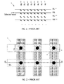
- a resistive memory array comprising a plurality of resistive memory elements, typically comprises a cross-bar array of top and bottom electrodes as illustrated schematically in FIG. 1 , in top view in FIG. 2 , and in cross-section in FIG.3 .
- the resistive memory device 1 comprises a plurality of top electrodes (e.g. wordlines WL) and a plurality of bottom electrodes (e.g. bit lines BL) which, together with an active layer 2 between the top and bottom electrodes, form a plurality of cross-point memory elements.
- the active layer 2 is interposed between the plurality of wordlines WL and bit lines BL.
- a programmable region i.e.
- a bit 3 is formed in the active layer 2.
- the resistivity of the bit 3 can be changed for example due to filament formation or filament disruption in response to a voltage or current applied between the corresponding wordline WL and the bit line BL.
- the position of the filaments are schematically indicated with closed circles 4 in FIG. 2 . Supposing that the world lines WL and the bit lines BL each have a width F being the minimum width obtainable with a given technology, the density of the resistive memory device 1 as illustrated in FIG. 2 can be calculated to be 1 filament/4F 2 , thus 1 bit/4F 2 .
- raw cross-point arrays with single RRAM elements lead to a large parasitic current flowing through non-selected memory cells.
- raw cross-point arrays suffer from READ errors (sneak currents) and possibly from PROGRAM errors, as well as from excessive current and power consumption.
- selector 5 in each cell, as illustrated in FIG. 4 .
- this can be a transistor, requiring the addition of another control wordline 6, but also a (bipolar) diode/switch device has been proposed as a selector 5.
- resistive memory arrays comprising memory cells including selection transistors are given in US2009/014836 .
- the present invention provides a resistive memory array comprising a plurality of resistive memory elements, a plurality of first lines each associated with at least one resistive memory element and arranged substantially in a first direction, a plurality of second lines each associated with at least one resistive memory element and arranged substantially in a second direction different from the first direction, and a plurality of third lines for controlling conductivity of the plurality of first lines. It is an advantage of a resistive memory array according to embodiments of the present invention that no selector needs to be provided in each cell, hence that small cell sizes may be obtained.
- the plurality of third lines may be arranged in the first direction. This way they can more easily influence the conductivity of the plurality of first lines in a transistor-like manner.
- the plurality of third lines may overlay the plurality of first lines or vice versa.
- the first direction and the second direction may be substantially orthogonal directions.
- the first direction and the second direction may be along circles and radii of these circles, respectively, or vice versa.
- Any third line may be associated with one of the first lines.
- a conductive electrode layer may be provided between the resistive memory elements and the first lines.
- the memory elements may be logically arranged in rows and columns, in a 2D configuration. In alternative embodiments, the memory elements may be logically arranged in stacks of rows and columns, in a 3D configuration.
- the resistive memory array being manufactured on a substrate having a major surface
- the first lines and the second lines may both be arranged parallel to the major surface.
- a plurality of layers comprising first lines and second lines may be stacked in a direction perpendicular to the major surface, so as to obtain a 3D structure.
- the first lines may be arranged parallel to the wafer surface, and the second lines may be arranged substantially perpendicular to the major surface, or vice versa. Also this way, a 3D structure is obtained.
- the present invention provides a method of manufacturing a resistive memory array.
- the method comprises providing a plurality of resistive memory elements, providing a plurality of first lines each associated with at least one resistive memory element and arranged substantially in a first direction, providing a plurality of second lines each associated with at least one resistive memory element and arranged substantially in a second direction different from the first direction, and providing a plurality of third lines for controlling conductivity of the plurality of first lines.
- providing a plurality of first lines may comprise providing the plurality of first lines in a plane parallel to a major surface of a substrate and providing a plurality of second lines may comprise providing the plurality of second lines in a plane parallel to the major surface of the substrate. This way, a 2D configuration is provided.
- providing a plurality of first lines may comprise providing the plurality of first lines in a plane parallel to a major surface of a substrate and providing a plurality of second lines may comprise providing the plurality of second lines substantially perpendicular to the major surface of the substrate. This way, a 3D configuration is provided.
- providing a plurality of first lines may comprise providing the plurality of first lines substantially perpendicular to the major surface of the substrate and providing a plurality of second lines may comprise providing the plurality of second lines in a plane parallel to a major surface of a substrate. Also this way a 3D configuration is provided.
- a resistive random-access memory is a non-volatile memory type having as basic idea that a dielectric, which is normally insulating, can be made to conduct through a filament or conduction path formed after application of a sufficiently high voltage. Once the filament is formed, it may be reset (broken, resulting in high resistance) or set (reformed, resulting in lower resistance) by an appropriately applied voltage.
- a pure RRAM memory element is used as a basic memory cell, resulting in a configuration where parallel bitlines are crossed by perpendicular wordlines with the switching material placed between wordline and bitline at every cross-point.
- this architecture large parasitic currents flow through non-selected memory cells.
- FIG. 5 schematically illustrates a portion of a resistive memory array 10 according to embodiments of the present invention.
- the resistive memory array 10 comprises a plurality of resistive memory elements 11 logically arranged in rows and columns.
- the terms “horizontal” and “vertical” (related to the terms “row” and “column” respectively) are used to provide a co-ordinate system and for ease of explanation only. They do not need to, but may, refer to an actual physical direction of the device.
- the terms “column” and “row” are used to describe sets of array elements which are linked together. The linking can be in the form of a Cartesian array of rows and columns; however, the present invention is not limited thereto.
- rows and columns can be easily interchanged and it is intended in this disclosure that these terms be interchangeable.
- non-Cartesian arrays may be constructed and are included within the scope of the invention. Accordingly the terms “row” and “column” should be interpreted widely. To facilitate in this wide interpretation, the claims refer to logically organised in rows and columns. By this is meant that sets of memory elements are linked together in a topologically linear intersecting manner; however, that the physical or topographical arrangement need not be so.
- the rows may be circles and the columns radii of these circles and the circles and radii are described in this invention as "logically organized" rows and columns.
- the resistive memory array 10 furthermore comprises a plurality of wordlines WL i arranged in the direction of the rows of memory elements 11, and a plurality of bitlines BL j arranged in the direction of the columns of memory elements 11, or vice versa.
- the wordlines WL i and the bitlines BL j are arranged in the form of a Cartesian array
- the wordlines WL i are parallel to one another
- the bitlines BL j are parallel to one another.
- the wordlines WL i may be arranged perpendicular to the bitlines BL j .
- the wordlines WL i may be arranged as concentric circles and the bitlines BL j may be arranged as radii of these circles, or vice versa.
- Specific names of the various lines, e.g. wordline and bitline, are intended to be generic names used to facilitate the explanation and to refer to a particular function and this specific choice of words is not intended to in any way limit the invention. It should be understood that all these terms are used only to facilitate a better understanding of the specific structure being described, and are in no way intended to limit the invention.
- the wordlines WL i are implemented as a select device.
- the wordlines can be made conducting or non-conducting (switched on or off).
- a control line is provided adjacent the wordlines, e.g. on top of the wordlines if the wordlines are placed above the bitlines in parallel planes or below the wordlines if the wordlines are placed below the bitlines in parallel planes, or adjacent the wordlines in a vertical layout in a configuration where bitlines are laid out in parallel planes, and wordlines are laid out perpendicular to the plane of the bitlines, as will be detailed below.
- a resistive memory array 10 is proposed, where wordlines WLi are laid out in a first plane, and bitlines BLj are laid out in a second plane parallel to the first plane.
- a method of manufacturing may be as follows.
- a substrate 12 is provided.
- the term “substrate” may include any underlying material or materials that may be used, or upon which a device according to embodiments of the present invention may be formed.
- this "substrate” may include a semiconductor substrate such as e.g. a silicon, a gallium arsenide (GaAs), a gallium arsenide phosphide (GaAsP), an indium phosphide (InP), a germanium (Ge), or a silicon germanium (SiGe) substrate.
- a semiconductor substrate such as e.g. a silicon, a gallium arsenide (GaAs), a gallium arsenide phosphide (GaAsP), an indium phosphide (InP), a germanium (Ge), or a silicon germanium (SiGe) substrate.
- the "substrate” may include, for example, an insulating layer such as a SiO 2 or a Si 3 N 4 layer in addition to a semiconductor substrate portion.
- the term substrate also includes silicon-on-glass, silicon-on sapphire substrates.
- the term “substrate” is thus used to define generally the elements for layers that underlie a layer or portions of interest.
- the “substrate” may be any other base on which a layer is formed, for example a glass or metal layer.
- the substrate 12 may be made of any suitable material, whether amorphous, polycrystalline or crystalline, such as LaAlO 3 , Si, TiN or other material.
- bitlines BL j-1 , BL j , BL j+1 are provided on or in a major surface of the substrate 12.
- the bitlines are made of conductive material including metals, e.g. poly-silicon, TiSiC, C, TiW, SiC, Ti, V, W, Cr, Fe, Ni, Nb, Pd, Pt, Zr, Mo, Cu, Al, Ag, Au, Hf and alloys thereof; conductive oxides e.g. IrO 2 , RuO 2 , IrRuO 3 , LiNbO 3 ; metal nitrides, e.g.
- the conductive material is a material such as YBa 2 Cu 3 O 7 (YBCO) that allows the epitaxial growth of an overlying perovskite material.
- the bitlines have a thickness in the range of between about 5 nm and about 500 nm.
- the bitlines may be formed by forming a trench in the substrate 112, depositing the conductive material and polishing the conductive material until level with the substrate 12. The polishing can be accomplished using chemical mechanical polishing (CMP) or other suitable means. Alternatively, the bitlines may be deposited and patterned without first forming a trench and without polishing.
- the active layer 13 is deposited overlying the plurality of bitlines BL j .
- the active layer 13 is made of a material capable of having its resistivity changed in response to an electrical signal.
- the active material may be a metal oxide (binary oxides from transition metals as NiO, HfO, TaO, ZrO, AIO, NbO, TiO, ...), optionally with a metallic cap layer (Hf, Ti, Al, Zr, ...) on one side, or complex oxides such as PrCaMnO (PCMO), or (doped) perovskite oxides, for example Cr:SrTi03, or it can be a solid electrolyte layer with incorporated Al or Cu, such as Cu(Al) Selenides or Tellerium compounds, or it can be combinations of multilayer stacks of different of the above layers combined.
- the active layer 13 can be phase change materials as e.g. GeSbTe, doped SbTe, or AsInSbTe.
- the active layer 13 may for example have a thickness between 5 nm and 500 nm.
- the active layer 13 can be deposited using any suitable deposition technique, including pulsed laser deposition, rf-sputtering, e-beam evaporation, thermal evaporation, atomic layer deposition, sol gel deposition, chemical vapour deposition.
- the active layer material is deposited over substantially the complete surface of the substrate 12, and is removed from outside the memory area by ion milling or any other suitable process. Alternatively it is also possible to form a large recess to thereover deposit active layer material, and then use a technique such as chemical mechanical polishing (CMP) to form the active layer 13.
- CMP chemical mechanical polishing
- a plurality of wordlines WL i overly the active layer 13, such that the active layer 13 is interposed between the bitlines BL j and the wordlines WL i .
- the wordlines are made of material of which the conductivity can be controlled, such as semiconductor material, e.g. silicon or poly-silicon or other suitable semiconductor materials. The doping concentration of the wordlines is limited by the need to be able to completely deplete it.
- the wordlines may be formed by depositing the suitable material, and patterning it so as to form the wordlines WL i .
- Wordlines WL i as bitlines BL j , may be present also outside the memory area, i.e. outside the area where active layer material 13 is present.
- the wordlines WL i and the bitlines BL j are each for example substantially parallel rows.
- the wordlines WL i and the bitlines BL j are arranged in a cross point arrangement such that they cross each other in a regular pattern.
- a cross point refers to each position where a wordline WL i crosses a bitline BL j .
- the wordlines WL i and the bitlines BL j are arranged at substantially 90 degrees with respect to one another.
- the resistive memory elements 11 are formed at the cross points between the wordlines WL i and the bitlines BL j .
- a dielectric layer 14 is provided over of the wordlines WL i .
- This layer can be made of any suitable dielectric material, such as for example Si02 or HfO 2 .
- the dielectric material 14 functions as a gate dielectric.
- the dielectric layer 14 may be patterned or not, but should remain present at least between the wordlines WL i and the control lines CWL i to be formed.
- control lines CWL i are provided, one control line associated with each wordline.
- the control lines CWL i are aligned with their associated wordlines WL i .
- the control lines CWL i are made of conductive material, e.g. any of the conductive materials suitable for forming the bitlines BL j , such as for example highly doped polysilicon. If semiconductor material is used for the control wordlines, the dopant concentration of this semiconductor material may be higher than the dopant concentration of the wordlines.
- the control lines CWL i when actuated, control the conductivity of the wordline WL i they are associated with. By making non-selected wordlines WL i non-conductive, sneak currents are dramatically reduced.
- bitlines BL j are present underneath the wordlines WL i
- bitlines BL j are present on top of the wordlines WL i .
- a substrate 12 is provided.
- a plurality of control lines CWL i are provided.
- a control line CWL i In the cross-sectional view of FIG. 7 , only one control line CWL i can be seen, but other control lines are provided in front of and/or behind this control line CWL i .
- all control lines are placed in a plane substantially parallel to the plane of the major surface of the substrate, and the individual control lines CWL i are placed substantially parallel with one another.
- control lines may be manufactured in a trench, by process steps as explained with respect to the bitlines BL j of the embodiment of FIG. 6 .
- control lines CWL i may be deposited and patterned on top of the major surface of the substrate 12; without first forming a trench in the substrate 12.
- a dielectric layer 14 is provided over of the control lines CWL i . This layer functions as a gate dielectric.
- the dielectric layer 14 may be patterned or not, but should remain present at least between the control lines CWL i and the wordlines WL i to be formed.
- a plurality of wordlines WL i are provided, one wordline WL i associated with each control line CWL i .
- the wordlines WL i are aligned with their associated control lines CWL i .
- the control lines CWL i when actuated, may control the conductivity of their associated wordlines WL i .
- An active layer 13 is deposited overlying the plurality of wordlines WL i which may be provided with or without planarization process such as dielectric filling or CMP.
- the active layer 13 is made of a material capable of having its resistivity changed in response to an electrical signal.
- the active layer 13 may for example have a thickness between 5 nm and 500 nm.
- the active layer 13 can be deposited using any suitable deposition technique, including pulsed laser deposition, rf-sputtering, e-beam evaporation, thermal evaporation, atomic layer deposition, sol gel deposition, chemical vapour deposition.
- the active layer material may be deposited over substantially the complete surface of the substrate 12, and removed from outside the memory area by wet or dry etching or any other suitable process. Alternatively it is also possible to form a large recess to thereover deposit active layer material, and then use a technique such as chemical mechanical polishing (CMP) to form the active layer 13.
- CMP chemical mechanical polishing
- Bitlines BL j are provided on top of the active layer 13, such that the active layer 13 is interposed between the bitlines BL j and the wordlines WL i .
- the wordlines WL i and the bitlines BL j are each for example substantially parallel rows.
- the wordlines WL i and the bitlines BL j are arranged in a cross point arrangement such that they cross each other in a regular pattern.
- a cross point refers to each position where a wordline WL i crosses a bitline BL j .
- the wordlines WL i and the bitlines BL j are arranged at substantially 90 degrees with respect to one another.
- the resistive memory elements 11 are formed at the cross points between the wordlines WL i and the bitlines BL j . Both wordlines WL i and bitlines BL j may be present also outside the memory area, i.e. outside the area where active layer material 13 is present.
- a conductive electrode 15, for example a metal electrode, such as for example a TiN electrode can be provided between the layer of switching material 13 and the wordlines WL i .
- This may improve programming characteristics of the device, in particular if the wordline material is not a good electrode material, such as e.g. poly.
- FIG. 8 and FIG. 9 vertical cross-sections in two substantially orthogonal directions, only for a third embodiment, corresponding to the configuration as in FIG. 7 provided with a supplementary conductive electrode between the wordlines and the layer of switching material, i.e.
- bitlines BL j on top of wordlines WL i
- this can also be applied to a fourth embodiment (not illustrated in the drawings) which is a configuration where the wordlines WL i are provided on top of the bitlines BL j as in FIG. 6 , but with a supplementary conductive electrode between the wordlines and the layer of switching material.
- This conductive electrode 15 is a region of small dimensions, substantially equal to the dimensions of the cross points between wordlines WL i and bitlines BL j . It may be manufactured by first, before forming the layer of resistive switching material, depositing a layer of conductive electrode material, e.g. metal, over the wordlines WL i already manufactured, and etching it back in between the wordlines WL i . This way, stripes of conductive electrode material, e.g. metal, are provided over the wordlines WL i . Thereafter, the layer of resistive switching material is provided over the wordlines WL i with stripes of conductive electrode material, e.g. metal, on top of which the bitlines BL j are formed.
- a layer of conductive electrode material e.g. metal
- an etching step takes place for defining lines in the direction of columns of resistive memory elements 11.
- this etching step also the layer of resistive switching material and the layer of conductive electrode material between this layer of resistive switching material and the wordlines WL i are etched.
- the layer of conductive electrode material is removed in between the bitlines BL j and in between the wordlines WL i , so that conductive electrodes 15 only remain at cross points of wordlines WL i and bitlines BL j .
- the layer of conductive electrode material is first etched to form stripes parallel with and overlying the bitlines BL j . Thereafter, during formation of the wordlines WL i , the layer of conductive electrode material is etched once again so as to remove electrode material remaining in between wordlines WL i . Also here conductive electrodes 15 only remain at cross points of wordlines WL i and bitlines BL j . In this case, the resistive switching layer does not necessarily need to be patterned so as to be present only at cross points between wordlines WL i and bitlines BL j .
- a further conductive electrode 16 for example e metal electrode such as e.g. a TiN electrode, may be present on top of (third embodiment, see FIG. 8 and 9 ) or underneath (fourth embodiment, configuration as in FIG. 6 , but not illustrated) the bitlines BL j .
- This further conductive electrode 16 may improve the electrical contact to the bitlines BL j .
- both wordlines WL i and bitlines BL j are provided both in a direction substantially parallel, e.g. parallel, to a major surface of the substrate 12. These are called 2D embodiments in the context of the present invention.
- the bitlines BL j may be provided substantially parallel, e.g. parallel, to a major surface of the substrate 12, and the wordlines WL i may be provided substantially perpendicular, e.g. perpendicular, to the major surface of the substrate 12, or the wordlines WL i may be provided substantially parallel, e.g. parallel, to a major surface of the substrate 12, and the bitlines BL j may be provided substantially perpendicular, e.g. perpendicular, to the major surface of the substrate 12.
- 3D embodiments in the context of the present invention, and they are explained hereinbelow.
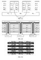
- a fifth embodiment of the present invention which is a first embodiment of a 3D configuration, is shown in side view in FIG. 10 and in top view in FIG. 11 .
- This is a 3D plug version of the resistive memory array, without intermediate electrode between wordline and resistive switching material.
- a similar 3D plug version of the resistive memory array can be provided, which is with intermediate electrode between wordline and resistive switching material.
- bitlines BL j and BL j+4 are provided adjacent one another substantially parallel, e.g. parallel, to the major surface of the substrate, thus forming a level of bitlines, and such levels of bitlines are stacked onto one another in a direction perpendicular to the substrate.
- a stack of at least two levels of bitlines may be made. The levels of bitlines are separated from one another by dielectric material.
- a stack of four levels of bitlines is made, the invention, however, not being limited thereto.
- the wordlines WL i and the control wordlines CWL i are provided. This may be obtained by providing a rolled-up stack (plug) of control wordline CWLi, dielectric material 14, wordline WLi and active switching material 13.
- This rolled-up stack is filled in a hole etched through the dielectric material 16 and the different bitlines BL j . This may be done by subsequently filling the hole with the relevant material and removing part of this material so as to make a new hole, to be filled with the next relevant material.
- the order of filling is active layer material, wordline material, dielectric material, control line material.
- a layer of electrode material is provided between the active layer material and the wordline material.
- connections to the wordline material and to the control wordline material need to be made, so as to enable access for driving the wordlines and control wordlines.
- connections to the wordline material may be made from the bottom, via a wordline WL i
- connections to the control wordline material may be made from the top, via a control wordline CWL i .
- FIG. 12 This is illustrated in FIG. 12 .
- the active layer 13 needs to be opened at the bottom side, e.g. by etching.
- the wordline material may also be opened at the bottom side.
- Wordline material is removed at the top side between the vertical stacks.
- connections to the wordline material may be made from the top, and connections to the control wordline material may be made from the bottom.
- a plug may be provided cutting through a stack of bitlines.
- a plug may be provided cutting through two neighbouring stacks of bitlines, for higher density of the memory array.
- the illustrated plug is cylindrical, circular in cross-section parallel to a major surface of the substrate, but in alternative embodiments a square plug could be provided with similar functionality. In yet other embodiments, the plug could have any suitable shape in cross-section.
- the wordlines and control wordlines can be provided in trenches.
- One method of manufacturing such 3D trench configuration is as follows, illustrated with respect to FIG. 13 to FIG. 17 .
- the substrate 12 may be a substrate as disclosed with respect to the 2D embodiments.
- the wordline may be made from conductive material of which the conductivity can be controlled by applying a voltage to another line adjacent to the wordline, for example semiconductor material such as silicon or polysilicon.
- semiconductor material such as silicon or polysilicon.
- the doping concentration of the wordlines is limited by the need to be able to completely deplete it.
- insulating material 16 is provided, such as e.g. SiO 2 , SiN, and in the insulating material 16 layers of bitlines BL j may be provided.
- the bitlines BL j are made of conductive material, including metals, e.g.
- poly-silicon TiSiC, C, TiW, SiC, Ti, V, W, Cr, Fe, Ni, Nb, Pd, Pt, Zr, Mo, Cu, Al, Ag, Au, Hf and alloys thereof; conductive oxides e.g. IrO 2 , RuO 2 , IrRuO 3 , LiNbO 3 ; metal nitrides, e.g. TiAIN, TiN, TaN, TiSiN, TiCN, TaSiN, MoN, TaAIN, WN; metal silicides e.g. TiSix, NiSix, CoSix; or combinations of any of the above.
- conductive oxides e.g. IrO 2 , RuO 2 , IrRuO 3 , LiNbO 3
- metal nitrides e.g. TiAIN, TiN, TaN, TiSiN, TiCN, TaSiN, MoN, TaAIN, WN
- metal silicides e.g.
- Providing the stack of insulating material 16 and bitlines BL j may be done by alternatingly depositing a layer of insulating material 16 and a layer of bitline material, so that the layers of bitline material are insulated from one another.
- the layers of bitline material are patterned such that in a layer of bitline material longitudinal bitlines BL j are formed, substantially parallel to one another and substantially parallel to the major surface of the substrate 12.
- Insulating material 16 is provided on top of the upper level of bitlines BL j .
- an etch stop layer 17 may be provided, such as for example amorphous carbon (APF) or Silicon Nitride (Si 3 N 4 ).
- a trench 18 is made through the stack of etch stop layer 17, insulating material 16 and bitlines BL j , down to the wordline WL i . This is illustrated in side view in FIG. 14 and in top view in FIG. 15 .
- the trench 18 is filled with a stack of a control wordline CWL i for controlling the conductivity of the wordline WL i , a dielectric layer 14 functioning as gate insulator between the control wordline CWLi and the wordline WLi, the wordline WLi itself and active material 13 forming the switching layer.
- a control wordline CWL i for controlling the conductivity of the wordline WL i
- a dielectric layer 14 functioning as gate insulator between the control wordline CWLi and the wordline WLi, the wordline WLi itself and active material 13 forming the switching layer.
- Such structure is illustrated in vertical cross-sectional view in FIG. 16 , and in a top view at level AA' in FIG. 17 . Suitable materials for those layers are indicated with respect to the 2D configurations.
- Filling up the trench 18 with such stack as defined above may be obtained by subsequently depositing the different layers and etching them back.
- the active material may be a metal oxide (binary oxides from transition metals as NiO, HfO, TaO, ZrO, AIO, NbO, TiO, ...), optionally with a metallic cap layer (Hf, Ti, Al, Zr, ...) on one side, or complex oxides such as PrCaMnO (PCMO), or (doped) perovskite oxides, for example Cr:SrTi03, or it can be a solid electrolyte layer with incorporated Al or Cu, such as Cu(Al) Selenides or Tellerium compounds, or it can be combinations of multilayer stacks of different of the above layers combined. Alternatively, it can be phase change materials as e.g.
- the trench 18 may be filled up with active material 13, after which the active material 13 may be partially removed, e.g. anisotropically etched, down to the etch stop layer 17 outside the trench 18, and down to the wordline WL i present on or in the substrate 12 in the trench 18. This way, active material 13 is only present at the sidewalls of the trench 18, not at the bottom thereof and neither outside the trench 18. Thereafter, a layer of wordline material is provided in the trench, at least covering the layer of active material 13, and making electrical contact with the wordline WL l present at the bottom of the trench 18. Again this may be obtained by substantially completely filling the trench with wordline material, and etching this material back.
- This etch back is performed such that wordline material remains present covering the layer of active material 13, and such that some of the wordline material remains present at the bottom of the trench, so as to make an electrical contact to the wordline WL i already present on or in the substrate 12, but such that a smaller trench is provided which can be filled with other material.
- a dielectric layer 14 is provided, covering the layer of wordline material. This may again be done by substantially completely filling the smaller trench with dielectric material, and partially removing the dielectric material from within the trench so as to provide a yet smaller trench. This latter trench is filled with control wordline material, and control wordline material is also provided on top of the stack.
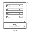
- a photoresist or hardmask 19 is provided over the structures obtained, as illustrated in top view in FIG. 18 , for allowing etching of perpendicular stripes.
- This photoresist or hardmask 19 is used for selectively etching control wordlines CWL i , dielectric layer 14 and wordlines WL i .
- the top etch stop layer 17 and the active layer 13 are not etched.
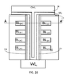
- the stack at the level A-A' as in FIG. 16 , looks like illustrated in FIG. 19 .
- These transversal trenches 20 are then filled with insulating material 21 such as e.g. SiO 2 (not illustrated in FIG. 19 ).
- insulating material 21 such as e.g. SiO 2 (not illustrated in FIG. 19 ).
- the obtained structure looks like FIG. 20 , i.e. a plurality of control wordlines CWLi are provided, each underneath them connecting to control wordline material inside the former trench 18.
- a plurality of blocks as illustrated in FIG. 10 or in FIG. 12 can be placed adjacent one another. This results in a structure as in FIG. 21 , the structure in FIG. 21 being illustrated for sake of ease without the trench being filled.
- bitlines BL j between two different wordlines WL i-1 , WL i , WL i+1 , i.e. at locations indicated with 22 in FIG. 21 do not need to be etched.
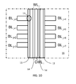
- a memory array 10 could look in vertical cross-sectional view like FIG. 22 , or in top view like FIG. 23 . This means that a same bitline is connected, via different resistive memory elements 11, to different adjacent wordlines WL i , WL i+1 . This is not a problem if at any time at least one of the neighbouring wordlines WL i , WL i+1 is put in a non-conducting state. This can be obtained by biasing the control lines CWL i .
- the above 3D configurations have bitline planes substantially parallel to a major surface of a substrate, and vertical wordlines, substantially perpendicular to the major surface of the substrate.
- the manufacturing flow with trenches has an advantage in scaling over plug versions (fifth and sixth embodiments) because in a plug version the width of the plug is determined in both dimensions of the cross-section by the thickness of the different filling layers, while in the trench version only one dimension (the one parallel to the trench width) is limited in scaling by this layer stack thickness, while the other dimension is only limited by patterning (litho + etch) and can be made potentially smaller resulting in a smaller cell area, hence a larger cell density.
- integration complexity of trench type arrays is increased because of the required etch through different materials.
- bitlines are provided in vertical trenches, and wordlines are provided perpendicular thereto. This is illustrated in the following manufacturing flow.
- a substrate 12 is provided.
- the substrate 12 may be as in any of the previous embodiments.
- the conductive material 24 will function as wordlines.
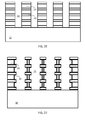
- a plurality of trenches 31 are provided in the layer stack, as illustrated in top view in FIG. 25 and in vertical cross-sectional view in FIG. 26 . Thereafter, the conductive material is recessed, i.e. pulled back in lateral direction, as illustrated in vertical cross-sectional view in FIG. 27 .
- a thin layer of insulating material 26 is provided in the recesses, for example a layer of SiO 2 formed by oxidation of the polysilicon. This layer of insulating material 26 will later on serve as a gate dielectric.
- the formed recesses are then filled with conductive semiconductor material 27 of which the conductivity can be controlled by applying an electrical signal to a gate, such as for example polysilicon.
- a gate such as for example polysilicon.
- FIG. 28 This can be obtained by substantially completely filling the trenches 31 and formed recesses with conductive semiconductor material 27, and then etching the trenches 31 again, as such leaving the conductive semiconductor material 27, e.g. polysilicon, only in the recesses.
- the active material may be any of the suitable active materials mentioned with reference to the previous embodiments.
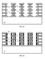
- the trench inside the active material 28 is then filled with conductive material for forming the bitlines 29. Any of the conductive materials used for forming bitlines in previous embodiments can also be used in this embodiment. This is illustrated in FIG. 29 .
- Memory elements 11 are formed by the active material 28 between wordlines 27 and bitlines 29. At this moment in the process, a top view only shows bitline material everywhere.
- bitlines are formed.
- trenches 32 are formed through the complete stack. This is illustrated in a top view of FIG. 29 after trench 32 formation in FIG. 30 , and in a vertical cross-sectional view in a direction substantially perpendicular to the cross-sectional view of FIG. 29 in FIG. 31 .
- a tenth embodiment, of a 3D configuration where bitlines are provided in vertical trenches, and wordlines are provided perpendicular thereto the start of the manufacturing process is up to the situation as illustrated in FIG. 28 .
- the conductive semiconductor material 27 is recessed, as illustrated in FIG. 32 .
- the formed recesses are filled with conductive material 30 such as TiN, which provides a better contact between the active material 28 to be provided and the wordlines 27. This is illustrated in FIG. 33 .
- the manufacturing method continues as before, with provision of the layer of active material 28 and provision of the bitlines 29.
- the resulting structure is illustrated in FIG. 34 .
- the wordlines are implemented as very long transistors. This alleviates the need for selectors in every cell, hence saving area and thus allowing memory arrays with higher density. It is an advantage of embodiments of the present invention that the wordlines are disappearing if not actuated, as they are pinched off by control wordlines.
Landscapes
- Semiconductor Memories (AREA)
Abstract
A resistive memory array (10) comprises a plurality of resistive memory elements (11), a plurality of first lines (WLi) each associated with at least one resistive memory element (11), and arranged substantially in a first direction, a plurality of second lines (BLj) each associated with at least one resistive memory element (11), and arranged substantially in a second direction different from the first direction, and a plurality of third lines (CWLi) controlling conductivity of the plurality of first lines (WLi). The third lines for controlling conductivity of the plurality of first lines replace cell selectors as known in the art. The present invention also provides a method of manufacturing such resistive memory array (10).
Description
- The present invention relates to semiconductor memory devices, more particularly to arrays of non-volatile memory cells comprising a reversible resistance switching layer, their resistance value being representative of the data stored in the memory cell. The present invention in particular relates to a new array design for minimizing design area and to methods of fabrication thereof.
- A resistive memory device, such as for example the electrically programmable resistive cross point memory device as described in
US2003/0003674 , is a non-volatile memory device which generally comprises an active layer capable of having its resistivity changed in response to an electrical signal, interposed between a plurality of conductive top and bottom electrodes. The active layer usually comprises a dielectric material, such as for example one or more metal oxide layers, a solid electrolyte material, a magnetic tunnel junction or a phase change material, which may be interposed between two conductive electrodes, for example wire-shaped Pt, W or TiN electrodes. At a cross point of a top electrode and a bottom electrode, a cross point referring to each position where a top electrode crosses a bottom electrode, the active layer has a programmable region with a resistivity that can change in response to an applied voltage. The memory effect of the resistive memory device lies in the programming of the memory device into two distinct resistive states.. - A resistive memory array, comprising a plurality of resistive memory elements, typically comprises a cross-bar array of top and bottom electrodes as illustrated schematically in
FIG. 1 , in top view inFIG. 2 , and in cross-section inFIG.3 . Theresistive memory device 1 comprises a plurality of top electrodes (e.g. wordlines WL) and a plurality of bottom electrodes (e.g. bit lines BL) which, together with anactive layer 2 between the top and bottom electrodes, form a plurality of cross-point memory elements. Theactive layer 2 is interposed between the plurality of wordlines WL and bit lines BL. At each crossing of a wordline WL with a bit line BL, a programmable region, i.e. abit 3, is formed in theactive layer 2. The resistivity of thebit 3 can be changed for example due to filament formation or filament disruption in response to a voltage or current applied between the corresponding wordline WL and the bit line BL. The position of the filaments are schematically indicated with closedcircles 4 inFIG. 2 . Supposing that the world lines WL and the bit lines BL each have a width F being the minimum width obtainable with a given technology, the density of theresistive memory device 1 as illustrated inFIG. 2 can be calculated to be 1 filament/4F2, thus 1 bit/4F2. - Such raw cross-point arrays with single RRAM elements lead to a large parasitic current flowing through non-selected memory cells. Hence raw cross-point arrays suffer from READ errors (sneak currents) and possibly from PROGRAM errors, as well as from excessive current and power consumption.
- One solution to alleviate these problems is to put a
selector 5 in each cell, as illustrated inFIG. 4 . Ideally this can be a transistor, requiring the addition of anothercontrol wordline 6, but also a (bipolar) diode/switch device has been proposed as aselector 5. Examples of resistive memory arrays comprising memory cells including selection transistors are given inUS2009/014836 . - Disadvantages of solutions including a
selector 5 in each cell are the increase of the cell size, hence the reduced memory density, the more complex processing - not a simple cross-point array but requiring the definition of intermediate pillar elements -, and the fact that no appropriate 2D terminal bipolar selector devices have been identified - bipolar devices require less chip area than MOS devices but are less process friendly. - Accordingly, there is room for new structures and processing methods for manufacturing non-volatile memory cells, which allow a high cell density.
- It is an object of embodiments of the present invention to provide high density non-volatile resistive memory arrays having limited READ and/or PROGRAM errors.
- The above objective is accomplished by a method and device according to the present invention.
- In a first aspect, the present invention provides a resistive memory array comprising a plurality of resistive memory elements, a plurality of first lines each associated with at least one resistive memory element and arranged substantially in a first direction, a plurality of second lines each associated with at least one resistive memory element and arranged substantially in a second direction different from the first direction, and a plurality of third lines for controlling conductivity of the plurality of first lines. It is an advantage of a resistive memory array according to embodiments of the present invention that no selector needs to be provided in each cell, hence that small cell sizes may be obtained.
- The plurality of third lines may be arranged in the first direction. This way they can more easily influence the conductivity of the plurality of first lines in a transistor-like manner. In particular embodiments of the present invention, the plurality of third lines may overlay the plurality of first lines or vice versa.
- In a resistive memory array according to embodiments of the present invention, the first direction and the second direction may be substantially orthogonal directions. In alternative embodiments, the first direction and the second direction may be along circles and radii of these circles, respectively, or vice versa.
- Any third line may be associated with one of the first lines.
- In a resistive memory array according to embodiments of the present invention, a conductive electrode layer may be provided between the resistive memory elements and the first lines.
- In a resistive memory array according to embodiments of the present invention, the memory elements may be logically arranged in rows and columns, in a 2D configuration. In alternative embodiments, the memory elements may be logically arranged in stacks of rows and columns, in a 3D configuration.
- In a resistive memory array according to embodiments of the present invention, the resistive memory array being manufactured on a substrate having a major surface, the first lines and the second lines may both be arranged parallel to the major surface. A plurality of layers comprising first lines and second lines may be stacked in a direction perpendicular to the major surface, so as to obtain a 3D structure.
- In a resistive memory array according to alternative embodiments of the present invention, the first lines may be arranged parallel to the wafer surface, and the second lines may be arranged substantially perpendicular to the major surface, or vice versa. Also this way, a 3D structure is obtained.
- In a second aspect, the present invention provides a method of manufacturing a resistive memory array. The method comprises providing a plurality of resistive memory elements, providing a plurality of first lines each associated with at least one resistive memory element and arranged substantially in a first direction, providing a plurality of second lines each associated with at least one resistive memory element and arranged substantially in a second direction different from the first direction, and providing a plurality of third lines for controlling conductivity of the plurality of first lines.
- In a method according to embodiments of the present invention, providing a plurality of first lines may comprise providing the plurality of first lines in a plane parallel to a major surface of a substrate and providing a plurality of second lines may comprise providing the plurality of second lines in a plane parallel to the major surface of the substrate. This way, a 2D configuration is provided.
- In a method according to alternative embodiments of the present invention, providing a plurality of first lines may comprise providing the plurality of first lines in a plane parallel to a major surface of a substrate and providing a plurality of second lines may comprise providing the plurality of second lines substantially perpendicular to the major surface of the substrate. This way, a 3D configuration is provided.
- In a method according to yet alternative embodiments of the present invention, providing a plurality of first lines may comprise providing the plurality of first lines substantially perpendicular to the major surface of the substrate and providing a plurality of second lines may comprise providing the plurality of second lines in a plane parallel to a major surface of a substrate. Also this way a 3D configuration is provided.
- It is an advantage of embodiments of the present invention that cells with the smallest cell size in a raw cross-point array can be realized, thereby, however, reducing sneak currents compared to a prior art raw cross-point array, or even avoiding these.
- Particular and preferred aspects of the invention are set out in the accompanying independent and dependent claims. Features from the dependent claims may be combined with features of the independent claims and with features of other dependent claims as appropriate and not merely as explicitly set out in the claims.
- For purposes of summarizing the invention and the advantages achieved over the prior art, certain objects and advantages of the invention have been described herein above. Of course, it is to be understood that not necessarily all such objects or advantages may be achieved in accordance with any particular embodiment of the invention. Thus, for example, those skilled in the art will recognize that the invention may be embodied or carried out in a manner that achieves or optimizes one advantage or group of advantages as taught herein without necessarily achieving other objects or advantages as may be taught or suggested herein.
- The above and other aspects of the invention will be apparent from and elucidated with reference to the embodiment(s) described hereinafter.
- The invention will now be described further, by way of example, with reference to the accompanying drawings, in which:
-
FIG. 1 is a schematic illustration of a prior art resistive memory raw cross-point array with a cross-bar array configuration of the top electrodes and the bottom electrodes. -
FIG. 2 is a top view of a portion of a prior art resistive memory array as inFIG. 1 . -
FIG. 3 is a cross-sectional view of the portion of a prior art resistive memory array ofFIG. 2 , taken along section A-A inFIG. 2 . The shaded zones are the programmable regions in the active layer with changeable resistivity. -
FIG. 4 is a schematic illustration of a prior art resistive memory array including a selector in each memory cell. -
FIG. 5 is a schematic illustration of a resistive memory array including a selector integrated in a wordline in accordance with embodiments of the present invention. -
FIG. 6 is a vertical cross-section of a first embodiment of a resistive memory array in a 2D configuration according to the present invention, where the bitlines are provided at the bottom and the wordlines and control wordlines are provided at the top, and where no intermediate electrode is provided between the wordlines and the resistive memory elements. -
FIG. 7 is a vertical cross-section of a second embodiment of a resistive memory array in a 2D configuration according to the present invention, where the wordlines and control wordlines are provided at the bottom and the bitlines are provided at the top, and where no intermediate electrode is provided between the wordlines and the resistive memory elements. -
FIG.8 and FIG.9 illustrate a third embodiment of a resistive memory array in a 2D configuration, where conductive material is provided between the wordlines and the resistive memory elements. In this third embodiment, bitlines are provided at the top, and the wordlines and control wordlines are provided at the bottom. -
FIG. 10 illustrates a vertical cross-sectional view of a basic part of a resistive memory array in a 3D configuration according to a fifth embodiment of the present invention, which is a plug version without intermediate electrode between the wordline and the resistive memory element. A complete array comprises a plurality of such basic parts that are connected like for example depicted inFIG. 21 . -
FIG. 11 is a top view of the memory array ofFIG. 10 . -
FIG. 12 illustrates yet another vertical cross-sectional view of a resistive memory array in a 3D configuration according to embodiments of the present invention. -
FIG. 13 to FIG. 20 illustrate different steps in a process flow for manufacturing a resistive memory array in a 3D configuration according to embodiments of the present invention. The 3D configuration manufactured according to this flow is a resistive memory array according to a seventh embodiment of the present invention, which is a trench version without intermediate electrode between wordlines and resistive memory material. -
FIG. 21 illustrates a memory array according to the seventh embodiment of the present invention (3D trench version without intermediate electrode between wordlines and resistive memory material), with interrupted bitlines between neighboring wordlines. -
FIG. 22 illustrates a memory array according to an eighth embodiment of the present invention, which is a 3D trench version without intermediate electrode between wordlines and resistive memory material, but with continuous bitlines between neighboring wordlines. -
FIG. 23 illustrates a top view of the array ofFIG. 22 . -
FIG. 24 to FIG. 31 illustrate different steps in a process flow for manufacturing a resistive memory array in a 3D configuration according to a ninth embodiment of the present invention. The resistive memory array is of a 3D trench type, with bitlines vertical and without intermediate electrode between the wordlines and the resistive material. -
FIG. 32 to FIG. 34 illustrate different steps in a process flow for manufacturing a resistive memory array in a 3D configuration according to a tenth embodiment of the present invention. The resistive memory array is of a 3D trench type, with intermediate electrode between the wordlines and the resistive material. - The drawings are only schematic and are non-limiting. In the drawings, the size of some of the elements may be exaggerated and not drawn on scale for illustrative purposes. The dimensions and the relative dimensions do not necessarily correspond to actual reductions to practice of the invention.
- Any reference signs in the claims shall not be construed as limiting the scope.
- In the different drawings, the same reference signs refer to the same or analogous elements.
- The present invention will be described with respect to particular embodiments and with reference to certain drawings but the invention is not limited thereto but only by the claims.
- The terms first, second and the like in the description and in the claims, are used for distinguishing between similar elements and not necessarily for describing a sequence, either temporally, spatially, in ranking or in any other manner. It is to be understood that the terms so used are interchangeable under appropriate circumstances and that the embodiments of the invention described herein are capable of operation in other sequences than described or illustrated herein.
- Moreover, the terms top, under and the like in the description and the claims are used for descriptive purposes and not necessarily for describing relative positions. It is to be understood that the terms so used are interchangeable under appropriate circumstances and that the embodiments of the invention described herein are capable of operation in other orientations than described or illustrated herein.
- It is to be noticed that the term "comprising", used in the claims, should not be interpreted as being restricted to the means listed thereafter; it does not exclude other elements or steps. It is thus to be interpreted as specifying the presence of the stated features, integers, steps or components as referred to, but does not preclude the presence or addition of one or more other features, integers, steps or components, or groups thereof. Thus, the scope of the expression "a device comprising means A and B" should not be limited to devices consisting only of components A and B. It means that with respect to the present invention, the only relevant components of the device are A and B.
- Reference throughout this specification to "one embodiment" or "an embodiment" means that a particular feature, structure or characteristic described in connection with the embodiment is included in at least one embodiment of the present invention. Thus, appearances of the phrases "in one embodiment" or "in an embodiment" in various places throughout this specification are not necessarily all referring to the same embodiment, but may. Furthermore, the particular features, structures or characteristics may be combined in any suitable manner, as would be apparent to one of ordinary skill in the art from this disclosure, in one or more embodiments.
- Similarly it should be appreciated that in the description of exemplary embodiments of the invention, various features of the invention are sometimes grouped together in a single embodiment, figure, or description thereof for the purpose of streamlining the disclosure and aiding in the understanding of one or more of the various inventive aspects. This method of disclosure, however, is not to be interpreted as reflecting an intention that the claimed invention requires more features than are expressly recited in each claim. Rather, as the following claims reflect, inventive aspects lie in less than all features of a single foregoing disclosed embodiment. Thus, the claims following the detailed description are hereby expressly incorporated into this detailed description, with each claim standing on its own as a separate embodiment of this invention.
- Furthermore, while some embodiments described herein include some but not other features included in other embodiments, combinations of features of different embodiments are meant to be within the scope of the invention, and form different embodiments, as would be understood by those in the art. For example, in the following claims, any of the claimed embodiments can be used in any combination.
- It should be noted that the use of particular terminology when describing certain features or aspects of the invention should not be taken to imply that the terminology is being re-defined herein to be restricted to include any specific characteristics of the features or aspects of the invention with which that terminology is associated.
- In the description provided herein, numerous specific details are set forth. However, it is understood that embodiments of the invention may be practiced without these specific details. In other instances, well-known methods, structures and techniques have not been shown in detail in order not to obscure an understanding of this description.
- In the context of the present invention, a resistive random-access memory (RRAM) is a non-volatile memory type having as basic idea that a dielectric, which is normally insulating, can be made to conduct through a filament or conduction path formed after application of a sufficiently high voltage. Once the filament is formed, it may be reset (broken, resulting in high resistance) or set (reformed, resulting in lower resistance) by an appropriately applied voltage.
- In a raw cross-point cell, a pure RRAM memory element is used as a basic memory cell, resulting in a configuration where parallel bitlines are crossed by perpendicular wordlines with the switching material placed between wordline and bitline at every cross-point. In this architecture, large parasitic currents flow through non-selected memory cells.
-
FIG. 5 schematically illustrates a portion of aresistive memory array 10 according to embodiments of the present invention. Theresistive memory array 10 comprises a plurality ofresistive memory elements 11 logically arranged in rows and columns. Throughout this description, the terms "horizontal" and "vertical" (related to the terms "row" and "column" respectively) are used to provide a co-ordinate system and for ease of explanation only. They do not need to, but may, refer to an actual physical direction of the device. Furthermore, the terms "column" and "row" are used to describe sets of array elements which are linked together. The linking can be in the form of a Cartesian array of rows and columns; however, the present invention is not limited thereto. As will be understood by those skilled in the art, columns and rows can be easily interchanged and it is intended in this disclosure that these terms be interchangeable. Also, non-Cartesian arrays may be constructed and are included within the scope of the invention. Accordingly the terms "row" and "column" should be interpreted widely. To facilitate in this wide interpretation, the claims refer to logically organised in rows and columns. By this is meant that sets of memory elements are linked together in a topologically linear intersecting manner; however, that the physical or topographical arrangement need not be so. For example, the rows may be circles and the columns radii of these circles and the circles and radii are described in this invention as "logically organized" rows and columns. - The
resistive memory array 10 furthermore comprises a plurality of wordlines WLi arranged in the direction of the rows ofmemory elements 11, and a plurality of bitlines BLj arranged in the direction of the columns ofmemory elements 11, or vice versa. In particular embodiments, where the wordlines WLi and the bitlines BLj are arranged in the form of a Cartesian array, the wordlines WLi are parallel to one another, and the bitlines BLj are parallel to one another. The wordlines WLi may be arranged perpendicular to the bitlines BLj. In alternative embodiments, the wordlines WLi may be arranged as concentric circles and the bitlines BLj may be arranged as radii of these circles, or vice versa. Specific names of the various lines, e.g. wordline and bitline, are intended to be generic names used to facilitate the explanation and to refer to a particular function and this specific choice of words is not intended to in any way limit the invention. It should be understood that all these terms are used only to facilitate a better understanding of the specific structure being described, and are in no way intended to limit the invention. - In accordance with embodiments of the present invention, the wordlines WLi are implemented as a select device. This means that, instead of putting a selector in each cell, as is done in prior art solutions, in accordance with embodiments of the present invention, the wordlines can be made conducting or non-conducting (switched on or off). Hereto, a control line is provided adjacent the wordlines, e.g. on top of the wordlines if the wordlines are placed above the bitlines in parallel planes or below the wordlines if the wordlines are placed below the bitlines in parallel planes, or adjacent the wordlines in a vertical layout in a configuration where bitlines are laid out in parallel planes, and wordlines are laid out perpendicular to the plane of the bitlines, as will be detailed below.
- In a first embodiment, as illustrated in a cross-sectional view in
FIG. 6 , aresistive memory array 10 is proposed, where wordlines WLi are laid out in a first plane, and bitlines BLj are laid out in a second plane parallel to the first plane. A method of manufacturing may be as follows. - First, a
substrate 12 is provided. In embodiments of the present invention, the term "substrate" may include any underlying material or materials that may be used, or upon which a device according to embodiments of the present invention may be formed. In alternative embodiments, this "substrate" may include a semiconductor substrate such as e.g. a silicon, a gallium arsenide (GaAs), a gallium arsenide phosphide (GaAsP), an indium phosphide (InP), a germanium (Ge), or a silicon germanium (SiGe) substrate. The "substrate" may include, for example, an insulating layer such as a SiO2 or a Si3N4 layer in addition to a semiconductor substrate portion. Thus, the term substrate also includes silicon-on-glass, silicon-on sapphire substrates. The term "substrate" is thus used to define generally the elements for layers that underlie a layer or portions of interest. Also, the "substrate" may be any other base on which a layer is formed, for example a glass or metal layer. As examples, thesubstrate 12 may be made of any suitable material, whether amorphous, polycrystalline or crystalline, such as LaAlO3, Si, TiN or other material. - On or in a major surface of the
substrate 12, a plurality of bitlines BLj-1, BLj, BLj+1 are provided. The bitlines are made of conductive material including metals, e.g. poly-silicon, TiSiC, C, TiW, SiC, Ti, V, W, Cr, Fe, Ni, Nb, Pd, Pt, Zr, Mo, Cu, Al, Ag, Au, Hf and alloys thereof; conductive oxides e.g. IrO2, RuO2, IrRuO3, LiNbO3; metal nitrides, e.g. TiAlN, TiN, TaN, TiSiN, TiCN, TaSiN, MoN, TaAlN, WN; metal silicides e.g. TiSix, NiSix, CoSix; or combinations of any of the above. In particular embodiments, the conductive material is a material such as YBa2Cu3O7 (YBCO) that allows the epitaxial growth of an overlying perovskite material. The bitlines have a thickness in the range of between about 5 nm and about 500 nm. In particular embodiments, the bitlines may be formed by forming a trench in the substrate 112, depositing the conductive material and polishing the conductive material until level with thesubstrate 12. The polishing can be accomplished using chemical mechanical polishing (CMP) or other suitable means. Alternatively, the bitlines may be deposited and patterned without first forming a trench and without polishing. - An
active layer 13 is deposited overlying the plurality of bitlines BLj. Theactive layer 13 is made of a material capable of having its resistivity changed in response to an electrical signal. The active material may be a metal oxide (binary oxides from transition metals as NiO, HfO, TaO, ZrO, AIO, NbO, TiO, ...), optionally with a metallic cap layer (Hf, Ti, Al, Zr, ...) on one side, or complex oxides such as PrCaMnO (PCMO), or (doped) perovskite oxides, for example Cr:SrTi03, or it can be a solid electrolyte layer with incorporated Al or Cu, such as Cu(Al) Selenides or Tellerium compounds, or it can be combinations of multilayer stacks of different of the above layers combined. Alternatively, it can be phase change materials as e.g. GeSbTe, doped SbTe, or AsInSbTe. Theactive layer 13 may for example have a thickness between 5 nm and 500 nm. Theactive layer 13 can be deposited using any suitable deposition technique, including pulsed laser deposition, rf-sputtering, e-beam evaporation, thermal evaporation, atomic layer deposition, sol gel deposition, chemical vapour deposition. The active layer material is deposited over substantially the complete surface of thesubstrate 12, and is removed from outside the memory area by ion milling or any other suitable process. Alternatively it is also possible to form a large recess to thereover deposit active layer material, and then use a technique such as chemical mechanical polishing (CMP) to form theactive layer 13. - A plurality of wordlines WLi, of which only one is visible in the cross-sectional view of
FIG. 6 , overly theactive layer 13, such that theactive layer 13 is interposed between the bitlines BLj and the wordlines WLi. The wordlines are made of material of which the conductivity can be controlled, such as semiconductor material, e.g. silicon or poly-silicon or other suitable semiconductor materials. The doping concentration of the wordlines is limited by the need to be able to completely deplete it. The wordlines may be formed by depositing the suitable material, and patterning it so as to form the wordlines WLi. Wordlines WLi, as bitlines BLj, may be present also outside the memory area, i.e. outside the area whereactive layer material 13 is present. - The wordlines WLi and the bitlines BLj are each for example substantially parallel rows. The wordlines WLi and the bitlines BLj are arranged in a cross point arrangement such that they cross each other in a regular pattern. A cross point refers to each position where a wordline WLi crosses a bitline BLj. As shown in the embodiment illustrated in
FIG. 6 , the wordlines WLi and the bitlines BLj are arranged at substantially 90 degrees with respect to one another. Theresistive memory elements 11 are formed at the cross points between the wordlines WLi and the bitlines BLj. - In accordance with embodiments of the present invention, a
dielectric layer 14 is provided over of the wordlines WLi. This layer can be made of any suitable dielectric material, such as for example Si02 or HfO2. Thedielectric material 14 functions as a gate dielectric. Thedielectric layer 14 may be patterned or not, but should remain present at least between the wordlines WLi and the control lines CWLi to be formed. - Over the
layer 14 of dielectric material, a plurality of control lines CWLi are provided, one control line associated with each wordline. The control lines CWLi are aligned with their associated wordlines WLi. The control lines CWLi are made of conductive material, e.g. any of the conductive materials suitable for forming the bitlines BLj, such as for example highly doped polysilicon. If semiconductor material is used for the control wordlines, the dopant concentration of this semiconductor material may be higher than the dopant concentration of the wordlines. The control lines CWLi, when actuated, control the conductivity of the wordline WLi they are associated with. By making non-selected wordlines WLi non-conductive, sneak currents are dramatically reduced. - In a second embodiment, as illustrated in
FIG. 7 , an inverse configuration is provided: where inFIG. 6 the bitlines BLj are present underneath the wordlines WLi, in the embodiment ofFIG. 7 the bitlines BLj are present on top of the wordlines WLi. - Materials used for the different layers may be similar or the same as the ones used and indicated with reference to the embodiment of
FIG. 6 . Only the manufacturing method is different. In this embodiment, first asubstrate 12 is provided. On or in a major surface of thesubstrate 12, a plurality of control lines CWLi are provided. In the cross-sectional view ofFIG. 7 , only one control line CWLi can be seen, but other control lines are provided in front of and/or behind this control line CWLi. In this embodiment, all control lines are placed in a plane substantially parallel to the plane of the major surface of the substrate, and the individual control lines CWLi are placed substantially parallel with one another. The control lines may be manufactured in a trench, by process steps as explained with respect to the bitlines BLj of the embodiment ofFIG. 6 . Alternatively, the control lines CWLi may be deposited and patterned on top of the major surface of thesubstrate 12; without first forming a trench in thesubstrate 12. - A
dielectric layer 14 is provided over of the control lines CWLi. This layer functions as a gate dielectric. Thedielectric layer 14 may be patterned or not, but should remain present at least between the control lines CWLi and the wordlines WLi to be formed. - Over the
layer 14 of dielectric material, a plurality of wordlines WLi are provided, one wordline WLi associated with each control line CWLi. The wordlines WLi are aligned with their associated control lines CWLi. The control lines CWLi, when actuated, may control the conductivity of their associated wordlines WLi. By making non-selected wordlines WLi non-conductive, sneak currents are dramatically reduced. - An
active layer 13 is deposited overlying the plurality of wordlines WLi which may be provided with or without planarization process such as dielectric filling or CMP. Theactive layer 13 is made of a material capable of having its resistivity changed in response to an electrical signal. Theactive layer 13 may for example have a thickness between 5 nm and 500 nm. Theactive layer 13 can be deposited using any suitable deposition technique, including pulsed laser deposition, rf-sputtering, e-beam evaporation, thermal evaporation, atomic layer deposition, sol gel deposition, chemical vapour deposition. The active layer material may be deposited over substantially the complete surface of thesubstrate 12, and removed from outside the memory area by wet or dry etching or any other suitable process. Alternatively it is also possible to form a large recess to thereover deposit active layer material, and then use a technique such as chemical mechanical polishing (CMP) to form theactive layer 13. - Bitlines BLj are provided on top of the
active layer 13, such that theactive layer 13 is interposed between the bitlines BLj and the wordlines WLi. The wordlines WLi and the bitlines BLj are each for example substantially parallel rows. The wordlines WLi and the bitlines BLj are arranged in a cross point arrangement such that they cross each other in a regular pattern. A cross point refers to each position where a wordline WLi crosses a bitline BLj. As shown in the embodiment illustrated inFIG. 7 , the wordlines WLi and the bitlines BLj are arranged at substantially 90 degrees with respect to one another. Theresistive memory elements 11 are formed at the cross points between the wordlines WLi and the bitlines BLj. Both wordlines WLi and bitlines BLj may be present also outside the memory area, i.e. outside the area whereactive layer material 13 is present. - In accordance with a third embodiment of the present invention, e.g. applicable in the configurations illustrated in
FIG. 6 and FIG. 7 , aconductive electrode 15, for example a metal electrode, such as for example a TiN electrode can be provided between the layer of switchingmaterial 13 and the wordlines WLi. This may improve programming characteristics of the device, in particular if the wordline material is not a good electrode material, such as e.g. poly. This is illustrated inFIG. 8 and FIG. 9 (vertical cross-sections in two substantially orthogonal directions), only for a third embodiment, corresponding to the configuration as inFIG. 7 provided with a supplementary conductive electrode between the wordlines and the layer of switching material, i.e. with bitlines BLj on top of wordlines WLi, but it will be clear for a person skilled in the art that this can also be applied to a fourth embodiment (not illustrated in the drawings) which is a configuration where the wordlines WLi are provided on top of the bitlines BLj as inFIG. 6 , but with a supplementary conductive electrode between the wordlines and the layer of switching material. - This
conductive electrode 15 is a region of small dimensions, substantially equal to the dimensions of the cross points between wordlines WLi and bitlines BLj. It may be manufactured by first, before forming the layer of resistive switching material, depositing a layer of conductive electrode material, e.g. metal, over the wordlines WLi already manufactured, and etching it back in between the wordlines WLi. This way, stripes of conductive electrode material, e.g. metal, are provided over the wordlines WLi. Thereafter, the layer of resistive switching material is provided over the wordlines WLi with stripes of conductive electrode material, e.g. metal, on top of which the bitlines BLj are formed. In the process of forming the bitlines BLj an etching step takes place for defining lines in the direction of columns ofresistive memory elements 11. During this etching step, also the layer of resistive switching material and the layer of conductive electrode material between this layer of resistive switching material and the wordlines WLi are etched. Hence the layer of conductive electrode material is removed in between the bitlines BLj and in between the wordlines WLi, so thatconductive electrodes 15 only remain at cross points of wordlines WLi and bitlines BLj. - If the inverse configuration is manufactured, with wordlines WLi on top of bitlines BLj, the layer of conductive electrode material is first etched to form stripes parallel with and overlying the bitlines BLj. Thereafter, during formation of the wordlines WLi, the layer of conductive electrode material is etched once again so as to remove electrode material remaining in between wordlines WLi. Also here
conductive electrodes 15 only remain at cross points of wordlines WLi and bitlines BLj. In this case, the resistive switching layer does not necessarily need to be patterned so as to be present only at cross points between wordlines WLi and bitlines BLj. - In embodiments of the present invention, a further
conductive electrode 16, for example e metal electrode such as e.g. a TiN electrode, may be present on top of (third embodiment, seeFIG. 8 and 9 ) or underneath (fourth embodiment, configuration as inFIG. 6 , but not illustrated) the bitlines BLj. This furtherconductive electrode 16 may improve the electrical contact to the bitlines BLj. - The above embodiments are embodiments where both wordlines WLi and bitlines BLj are provided both in a direction substantially parallel, e.g. parallel, to a major surface of the
substrate 12. These are called 2D embodiments in the context of the present invention. In alternative embodiments, the bitlines BLj may be provided substantially parallel, e.g. parallel, to a major surface of thesubstrate 12, and the wordlines WLi may be provided substantially perpendicular, e.g. perpendicular, to the major surface of thesubstrate 12, or the wordlines WLi may be provided substantially parallel, e.g. parallel, to a major surface of thesubstrate 12, and the bitlines BLj may be provided substantially perpendicular, e.g. perpendicular, to the major surface of thesubstrate 12. These are called 3D embodiments in the context of the present invention, and they are explained hereinbelow. - A fifth embodiment of the present invention, which is a first embodiment of a 3D configuration, is shown in side view in
FIG. 10 and in top view inFIG. 11 . This is a 3D plug version of the resistive memory array, without intermediate electrode between wordline and resistive switching material. In an alternative sixth embodiment, not illustrated in the drawings, a similar 3D plug version of the resistive memory array can be provided, which is with intermediate electrode between wordline and resistive switching material. - As can be seen in the illustrations of the fifth embodiment, substantially parallel or parallel to a major surface of a substrate (not illustrated), a plurality of bitlines BLj are stacked.
FIG. 10 andFIG. 11 illustrate one block ofmemory elements 11 which is repeated throughout amemory array 10. In the embodiment illustrated, bitlines BLj and BLj+4 are provided adjacent one another substantially parallel, e.g. parallel, to the major surface of the substrate, thus forming a level of bitlines, and such levels of bitlines are stacked onto one another in a direction perpendicular to the substrate. A stack of at least two levels of bitlines may be made. The levels of bitlines are separated from one another by dielectric material. In the embodiment illustrated, a stack of four levels of bitlines is made, the invention, however, not being limited thereto. Perpendicularly through the stack of bitlines, the wordlines WLi and the control wordlines CWLi are provided. This may be obtained by providing a rolled-up stack (plug) of control wordline CWLi,dielectric material 14, wordline WLi andactive switching material 13. This rolled-up stack is filled in a hole etched through thedielectric material 16 and the different bitlines BLj. This may be done by subsequently filling the hole with the relevant material and removing part of this material so as to make a new hole, to be filled with the next relevant material. The order of filling is active layer material, wordline material, dielectric material, control line material. In case of the sixth embodiment, a layer of electrode material is provided between the active layer material and the wordline material. - Once this plug is provided, connections to the wordline material and to the control wordline material need to be made, so as to enable access for driving the wordlines and control wordlines. As an example, connections to the wordline material may be made from the bottom, via a wordline WLi, and connections to the control wordline material may be made from the top, via a control wordline CWLi. This is illustrated in
FIG. 12 . Hereto, only theactive layer 13 needs to be opened at the bottom side, e.g. by etching. Optionally, the wordline material may also be opened at the bottom side. Wordline material is removed at the top side between the vertical stacks. In alternative embodiments, not illustrated in the drawings, connections to the wordline material may be made from the top, and connections to the control wordline material may be made from the bottom. - In embodiments of the present invention, a plug may be provided cutting through a stack of bitlines. Alternatively, as illustrated in
FIG.11 , a plug may be provided cutting through two neighbouring stacks of bitlines, for higher density of the memory array. - In
FIG. 11 , the illustrated plug is cylindrical, circular in cross-section parallel to a major surface of the substrate, but in alternative embodiments a square plug could be provided with similar functionality. In yet other embodiments, the plug could have any suitable shape in cross-section. - In alternative embodiments of the present invention, e.g. a seventh embodiment, rather than providing a plurality of plugs comprising the wordlines WLi and control wordlines CWLi, the wordlines and control wordlines can be provided in trenches. One method of manufacturing such 3D trench configuration is as follows, illustrated with respect to
FIG. 13 to FIG. 17 . - As illustrated in
FIG. 13 , on or in asubstrate 12, at least one wordline WLi is provided. Thesubstrate 12 may be a substrate as disclosed with respect to the 2D embodiments. The wordline may be made from conductive material of which the conductivity can be controlled by applying a voltage to another line adjacent to the wordline, for example semiconductor material such as silicon or polysilicon. The doping concentration of the wordlines is limited by the need to be able to completely deplete it. On top of the wordlines WLi, insulatingmaterial 16 is provided, such as e.g. SiO2, SiN, and in the insulatingmaterial 16 layers of bitlines BLj may be provided. The bitlines BLj are made of conductive material, including metals, e.g. poly-silicon, TiSiC, C, TiW, SiC, Ti, V, W, Cr, Fe, Ni, Nb, Pd, Pt, Zr, Mo, Cu, Al, Ag, Au, Hf and alloys thereof; conductive oxides e.g. IrO2, RuO2, IrRuO3, LiNbO3; metal nitrides, e.g. TiAIN, TiN, TaN, TiSiN, TiCN, TaSiN, MoN, TaAIN, WN; metal silicides e.g. TiSix, NiSix, CoSix; or combinations of any of the above. Providing the stack of insulatingmaterial 16 and bitlines BLj may be done by alternatingly depositing a layer of insulatingmaterial 16 and a layer of bitline material, so that the layers of bitline material are insulated from one another. The layers of bitline material are patterned such that in a layer of bitline material longitudinal bitlines BLj are formed, substantially parallel to one another and substantially parallel to the major surface of thesubstrate 12. Insulatingmaterial 16 is provided on top of the upper level of bitlines BLj. On top of the insulating material, anetch stop layer 17 may be provided, such as for example amorphous carbon (APF) or Silicon Nitride (Si3N4). - Once such stack is provided, a
trench 18 is made through the stack ofetch stop layer 17, insulatingmaterial 16 and bitlines BLj, down to the wordline WLi. This is illustrated in side view inFIG. 14 and in top view inFIG. 15 . - Thereafter, the
trench 18 is filled with a stack of a control wordline CWLi for controlling the conductivity of the wordline WLi, adielectric layer 14 functioning as gate insulator between the control wordline CWLi and the wordline WLi, the wordline WLi itself andactive material 13 forming the switching layer. Such structure is illustrated in vertical cross-sectional view inFIG. 16 , and in a top view at level AA' inFIG. 17 . Suitable materials for those layers are indicated with respect to the 2D configurations. - Filling up the
trench 18 with such stack as defined above may be obtained by subsequently depositing the different layers and etching them back. First a layer ofactive material 13, i.e. a material capable of having its resistivity changed in response to an electrical signal, is provided in thetrench 18. The active material may be a metal oxide (binary oxides from transition metals as NiO, HfO, TaO, ZrO, AIO, NbO, TiO, ...), optionally with a metallic cap layer (Hf, Ti, Al, Zr, ...) on one side, or complex oxides such as PrCaMnO (PCMO), or (doped) perovskite oxides, for example Cr:SrTi03, or it can be a solid electrolyte layer with incorporated Al or Cu, such as Cu(Al) Selenides or Tellerium compounds, or it can be combinations of multilayer stacks of different of the above layers combined. Alternatively, it can be phase change materials as e.g. GeSbTe, doped SbTe, or AsInSbTe. Thetrench 18 may be filled up withactive material 13, after which theactive material 13 may be partially removed, e.g. anisotropically etched, down to theetch stop layer 17 outside thetrench 18, and down to the wordline WLi present on or in thesubstrate 12 in thetrench 18. This way,active material 13 is only present at the sidewalls of thetrench 18, not at the bottom thereof and neither outside thetrench 18. Thereafter, a layer of wordline material is provided in the trench, at least covering the layer ofactive material 13, and making electrical contact with the wordline WLl present at the bottom of thetrench 18. Again this may be obtained by substantially completely filling the trench with wordline material, and etching this material back. This etch back is performed such that wordline material remains present covering the layer ofactive material 13, and such that some of the wordline material remains present at the bottom of the trench, so as to make an electrical contact to the wordline WLi already present on or in thesubstrate 12, but such that a smaller trench is provided which can be filled with other material. In this smaller trench, adielectric layer 14 is provided, covering the layer of wordline material. This may again be done by substantially completely filling the smaller trench with dielectric material, and partially removing the dielectric material from within the trench so as to provide a yet smaller trench. This latter trench is filled with control wordline material, and control wordline material is also provided on top of the stack. - After having filled the
trench 18 with the stack of layers as described, a photoresist orhardmask 19 is provided over the structures obtained, as illustrated in top view inFIG. 18 , for allowing etching of perpendicular stripes. - This photoresist or
hardmask 19 is used for selectively etching control wordlines CWLi,dielectric layer 14 and wordlines WLi. The topetch stop layer 17 and theactive layer 13 are not etched. - After the etching step, the stack, at the level A-A' as in
FIG. 16 , looks like illustrated inFIG. 19 . This means that the filled uptrench 18 is now cut bytransversal trenches 20. Thesetransversal trenches 20 are then filled with insulatingmaterial 21 such as e.g. SiO2 (not illustrated inFIG. 19 ). In top view at the top, the obtained structure looks likeFIG. 20 , i.e. a plurality of control wordlines CWLi are provided, each underneath them connecting to control wordline material inside theformer trench 18. - When forming a
resistive memory array 10 according to embodiments of the present invention, a plurality of blocks as illustrated inFIG. 10 or inFIG. 12 can be placed adjacent one another. This results in a structure as inFIG. 21 , the structure inFIG. 21 being illustrated for sake of ease without the trench being filled. - In an eighth embodiment, however, the bitlines BLj between two different wordlines WLi-1, WLi, WLi+1, i.e. at locations indicated with 22 in
FIG. 21 , do not need to be etched. Hence, in accordance with the eighth embodiment, amemory array 10 could look in vertical cross-sectional view likeFIG. 22 , or in top view likeFIG. 23 . This means that a same bitline is connected, via differentresistive memory elements 11, to different adjacent wordlines WLi, WLi+1. This is not a problem if at any time at least one of the neighbouring wordlines WLi, WLi+1 is put in a non-conducting state. This can be obtained by biasing the control lines CWLi. - The above 3D configurations have bitline planes substantially parallel to a major surface of a substrate, and vertical wordlines, substantially perpendicular to the major surface of the substrate. The manufacturing flow with trenches (seventh and eighth embodiments) has an advantage in scaling over plug versions (fifth and sixth embodiments) because in a plug version the width of the plug is determined in both dimensions of the cross-section by the thickness of the different filling layers, while in the trench version only one dimension (the one parallel to the trench width) is limited in scaling by this layer stack thickness, while the other dimension is only limited by patterning (litho + etch) and can be made potentially smaller resulting in a smaller cell area, hence a larger cell density. On the other hand, integration complexity of trench type arrays is increased because of the required etch through different materials.
- In ninth and tenth embodiments, a 3D configuration is provided where bitlines are provided in vertical trenches, and wordlines are provided perpendicular thereto. This is illustrated in the following manufacturing flow.
- For embodiments in accordance with the ninth embodiment, first, as illustrated in
FIG. 24 , asubstrate 12 is provided. Thesubstrate 12 may be as in any of the previous embodiments. On top of the substrate, a layer stack of alternating layers of insulatingmaterial 23 such as for example SiO2, andconductive material 24, such as for example metal or semiconductor material such as polysilicon, is provided. Theconductive material 24 will function as wordlines. - A plurality of
trenches 31 are provided in the layer stack, as illustrated in top view inFIG. 25 and in vertical cross-sectional view inFIG. 26 . Thereafter, the conductive material is recessed, i.e. pulled back in lateral direction, as illustrated in vertical cross-sectional view inFIG. 27 . A thin layer of insulatingmaterial 26 is provided in the recesses, for example a layer of SiO2 formed by oxidation of the polysilicon. This layer of insulatingmaterial 26 will later on serve as a gate dielectric. - The formed recesses are then filled with
conductive semiconductor material 27 of which the conductivity can be controlled by applying an electrical signal to a gate, such as for example polysilicon. This is illustrated inFIG. 28 . This can be obtained by substantially completely filling thetrenches 31 and formed recesses withconductive semiconductor material 27, and then etching thetrenches 31 again, as such leaving theconductive semiconductor material 27, e.g. polysilicon, only in the recesses. - Thereafter, a layer of
active material 28, i.e. a material capable of having its resistivity changed in response to an electrical signal, is provided all over the structure, for example by substantially completely filling thetrenches 31 withactive material 28 and then providing a smaller trench in theactive material 28. The active material may be any of the suitable active materials mentioned with reference to the previous embodiments. The trench inside theactive material 28 is then filled with conductive material for forming thebitlines 29. Any of the conductive materials used for forming bitlines in previous embodiments can also be used in this embodiment. This is illustrated inFIG. 29 .Memory elements 11 are formed by theactive material 28 betweenwordlines 27 andbitlines 29. At this moment in the process, a top view only shows bitline material everywhere. - In a next step, the bitlines are formed. Hereto,
trenches 32 are formed through the complete stack. This is illustrated in a top view ofFIG. 29 aftertrench 32 formation inFIG. 30 , and in a vertical cross-sectional view in a direction substantially perpendicular to the cross-sectional view ofFIG. 29 inFIG. 31 . - In an alternative embodiment, a tenth embodiment, of a 3D configuration where bitlines are provided in vertical trenches, and wordlines are provided perpendicular thereto, the start of the manufacturing process is up to the situation as illustrated in
FIG. 28 . Then theconductive semiconductor material 27 is recessed, as illustrated inFIG. 32 . The formed recesses are filled withconductive material 30 such as TiN, which provides a better contact between theactive material 28 to be provided and thewordlines 27. This is illustrated inFIG. 33 . Thereafter, the manufacturing method continues as before, with provision of the layer ofactive material 28 and provision of thebitlines 29. The resulting structure is illustrated inFIG. 34 . - Although all process flows are scalable, it is an advantage of this latter flow that it is more scalable than others.
- In general it is an advantage of embodiments of the present invention that the wordlines are implemented as very long transistors. This alleviates the need for selectors in every cell, hence saving area and thus allowing memory arrays with higher density. It is an advantage of embodiments of the present invention that the wordlines are disappearing if not actuated, as they are pinched off by control wordlines.
- While the invention has been illustrated and described in detail in the drawings and foregoing description, such illustration and description are to be considered illustrative or exemplary and not restrictive. The foregoing description details certain embodiments of the invention. It will be appreciated, however, that no matter how detailed the foregoing appears in text, the invention may be practiced in many ways. The invention is not limited to the disclosed embodiments.
Claims (15)
- A resistive memory array (10), comprising
a plurality of resistive memory elements (11),
a plurality of first lines (WLi) each associated with at least one resistive memory element (11), and arranged substantially in a first direction,
a plurality of second lines (BLj) each associated with at least one resistive memory element (11), and arranged substantially in a second direction different from the first direction, and
a plurality of third lines (CWLi) for controlling conductivity of the plurality of first lines (WLi). - A resistive memory array (10) according to claim 1, wherein the plurality of third lines (CWLi) are arranged in the first direction.
- A resistive memory array (10) according to claim 2, wherein the plurality of third lines (CWLi) overlay the plurality of first lines (WLi) or vice versa.
- A resistive memory array (10) according to any of the previous claims, wherein the first direction and the second direction are substantially orthogonal directions.
- A resistive memory array (10) according to any of claims 1 to 3, wherein the first direction and the second direction are along circles and radii of these circles, respectively, or vice versa.
- A resistive memory array (10) according to claim 1, wherein the plurality of third lines (CWLi) are arranged orthogonally to the first lines (WLi).
- A resistive memory array (10) according to any of the previous claims, wherein any third line (CWLi) is associated with one of the first lines (WLi).
- A resistive memory array (10) according to any of the previous claims, wherein a metal layer is provided between the resistive memory elements (11) and the first lines (WLi).
- A resistive memory array (10) according to any of the previous claims, the resistive memory array (10) being manufactured on a substrate having a major surface, wherein the first lines (WLi) and the second lines (BLj) are arranged parallel to the major surface.
- A resistive memory array (10) according to claim 9, wherein a plurality of layers comprising first lines (WLi) and the second lines (BLj) are stacked in a direction perpendicular to the major surface.
- A resistive memory array (10) according to any of claims 1 to 5 or 7 or 8, wherein the first lines (WLi) are arranged parallel to the wafer surface, and the second lines (BLj) are arranged substantially perpendicular to the major surface, or vice versa.
- A method of manufacturing a resistive memory array (10), comprising
providing a plurality of resistive memory elements (11),
providing a plurality of first lines (WLi) each associated with at least one resistive memory element (11), and arranged substantially in a first direction,
providing a plurality of second lines (BLj) each associated with at least one resistive memory element (11), and arranged substantially in a second direction different from the first direction, and
providing a plurality of third lines (CWLi) for controlling conductivity of the plurality of first lines (WLi). - A method according to claim 12, wherein providing a plurality of first lines comprises providing the plurality of first lines in a plane parallel to a major surface of a substrate (12) and wherein providing a plurality of second lines comprises providing the plurality of second lines in a plane parallel to the major surface of the substrate (12).
- A method according to claim 12, wherein providing a plurality of first lines comprises providing the plurality of first lines in a plane parallel to a major surface of a substrate (12) and wherein providing a plurality of second lines comprises providing the plurality of second lines substantially perpendicular to the major surface of the substrate (12).
- A method according to claim 12, wherein providing a plurality of first lines comprises providing the plurality of first lines substantially perpendicular to the major surface of the substrate (12) and wherein providing a plurality of second lines comprises providing the plurality of second lines in a plane parallel to a major surface of a substrate (12).
Priority Applications (1)
| Application Number | Priority Date | Filing Date | Title |
|---|---|---|---|
| EP11194761.0A EP2608209A1 (en) | 2011-12-21 | 2011-12-21 | Resistive memory array |
Applications Claiming Priority (1)
| Application Number | Priority Date | Filing Date | Title |
|---|---|---|---|
| EP11194761.0A EP2608209A1 (en) | 2011-12-21 | 2011-12-21 | Resistive memory array |
Publications (1)
| Publication Number | Publication Date |
|---|---|
| EP2608209A1 true EP2608209A1 (en) | 2013-06-26 |
Family
ID=45528900
Family Applications (1)
| Application Number | Title | Priority Date | Filing Date |
|---|---|---|---|
| EP11194761.0A Withdrawn EP2608209A1 (en) | 2011-12-21 | 2011-12-21 | Resistive memory array |
Country Status (1)
| Country | Link |
|---|---|
| EP (1) | EP2608209A1 (en) |
Citations (4)
| Publication number | Priority date | Publication date | Assignee | Title |
|---|---|---|---|---|
| US20030003674A1 (en) | 2001-06-28 | 2003-01-02 | Hsu Sheng Teng | Electrically programmable resistance cross point memory |
| US20090014836A1 (en) | 2007-07-10 | 2009-01-15 | Tzyh-Cheang Lee | Memory Array with a Selector Connected to Multiple Resistive Cells |
| WO2010018888A1 (en) * | 2008-08-14 | 2010-02-18 | Sung-Dong Kim | Three dimensional semiconductor device and methods of fabricating and operating the same |
| US20110096588A1 (en) * | 2009-10-26 | 2011-04-28 | Fasoli Luca G | Non-volatile memory array architecture incorporating 1t-1r near 4f2 memory cell |
-
2011
- 2011-12-21 EP EP11194761.0A patent/EP2608209A1/en not_active Withdrawn
Patent Citations (4)
| Publication number | Priority date | Publication date | Assignee | Title |
|---|---|---|---|---|
| US20030003674A1 (en) | 2001-06-28 | 2003-01-02 | Hsu Sheng Teng | Electrically programmable resistance cross point memory |
| US20090014836A1 (en) | 2007-07-10 | 2009-01-15 | Tzyh-Cheang Lee | Memory Array with a Selector Connected to Multiple Resistive Cells |
| WO2010018888A1 (en) * | 2008-08-14 | 2010-02-18 | Sung-Dong Kim | Three dimensional semiconductor device and methods of fabricating and operating the same |
| US20110096588A1 (en) * | 2009-10-26 | 2011-04-28 | Fasoli Luca G | Non-volatile memory array architecture incorporating 1t-1r near 4f2 memory cell |
Similar Documents
| Publication | Publication Date | Title |
|---|---|---|
| US9812505B2 (en) | Non-volatile memory device containing oxygen-scavenging material portions and method of making thereof | |
| EP2608210B1 (en) | Stacked RRAM array with integrated transistor selector | |
| EP3178113B1 (en) | Fully isolated selector for memory device | |
| US11456333B2 (en) | Three-dimensional NAND memory device containing two terminal selector and methods of using and making thereof | |
| US20200258940A1 (en) | Vertical cross-point memory arrays | |
| CN101924062B (en) | Memory device and method for manufacturing an integrated circuit device | |
| US10522595B2 (en) | Memory devices and methods of manufacturing the same | |
| KR101230874B1 (en) | Nonvolatile memory cell comprising switchable resistor and transistor | |
| US7910911B2 (en) | Phase change memory with tapered heater | |
| US7932506B2 (en) | Fully self-aligned pore-type memory cell having diode access device | |
| US9613689B1 (en) | Self-selecting local bit line for a three-dimensional memory array | |
| TWI497706B (en) | Mushroom type memory cell having self-aligned bottom electrode and diode access device | |
| CN102244194B (en) | Self-aligned Fin-Type Programmable Memory Cell | |
| CN101894854A (en) | Phase change memory cell with vertical channel access transistors and memory planes | |
| KR20130036279A (en) | Memory cell with resistance- switching layers and lateral arrangement | |
| US10957370B1 (en) | Integration of epitaxially grown channel selector with two terminal resistive switching memory element | |
| WO2013169551A1 (en) | Resistance- switching memory cells having reduced metal migration and low current operation | |
| US10622557B2 (en) | Cross-point array device and method of manufacturing the same | |
| CN112243527A (en) | Phase change memory device with wire threshold switching selector and method of forming the same | |
| KR101088487B1 (en) | Method for manufacturing resistance change memory device array, electronics and device array with selection device and 3D structure resistance change memory device | |
| KR101331859B1 (en) | 3-dimensional non-volatile memory device and method of fabricating the same | |
| KR101735146B1 (en) | 3-dimensional non-volatile memory device |
Legal Events
| Date | Code | Title | Description |
|---|---|---|---|
| AK | Designated contracting states |
Kind code of ref document: A1 Designated state(s): AL AT BE BG CH CY CZ DE DK EE ES FI FR GB GR HR HU IE IS IT LI LT LU LV MC MK MT NL NO PL PT RO RS SE SI SK SM TR |
|
| AX | Request for extension of the european patent |
Extension state: BA ME |
|
| PUAI | Public reference made under article 153(3) epc to a published international application that has entered the european phase |
Free format text: ORIGINAL CODE: 0009012 |
|
| STAA | Information on the status of an ep patent application or granted ep patent |
Free format text: STATUS: THE APPLICATION IS DEEMED TO BE WITHDRAWN |
|
| 18D | Application deemed to be withdrawn |
Effective date: 20140103 |